WO2015019697A1 - Moyen de projection d'huile - Google Patents
Moyen de projection d'huile Download PDFInfo
- Publication number
- WO2015019697A1 WO2015019697A1 PCT/JP2014/065216 JP2014065216W WO2015019697A1 WO 2015019697 A1 WO2015019697 A1 WO 2015019697A1 JP 2014065216 W JP2014065216 W JP 2014065216W WO 2015019697 A1 WO2015019697 A1 WO 2015019697A1
- Authority
- WO
- WIPO (PCT)
- Prior art keywords
- oil
- cylinder
- valve
- oil injection
- piston
- Prior art date
Links
Images
Classifications
-
- F—MECHANICAL ENGINEERING; LIGHTING; HEATING; WEAPONS; BLASTING
- F01—MACHINES OR ENGINES IN GENERAL; ENGINE PLANTS IN GENERAL; STEAM ENGINES
- F01P—COOLING OF MACHINES OR ENGINES IN GENERAL; COOLING OF INTERNAL-COMBUSTION ENGINES
- F01P3/00—Liquid cooling
- F01P3/06—Arrangements for cooling pistons
- F01P3/08—Cooling of piston exterior only, e.g. by jets
-
- F—MECHANICAL ENGINEERING; LIGHTING; HEATING; WEAPONS; BLASTING
- F01—MACHINES OR ENGINES IN GENERAL; ENGINE PLANTS IN GENERAL; STEAM ENGINES
- F01M—LUBRICATING OF MACHINES OR ENGINES IN GENERAL; LUBRICATING INTERNAL COMBUSTION ENGINES; CRANKCASE VENTILATING
- F01M1/00—Pressure lubrication
- F01M1/08—Lubricating systems characterised by the provision therein of lubricant jetting means
- F01M2001/083—Lubricating systems characterised by the provision therein of lubricant jetting means for lubricating cylinders
Definitions
- the present invention relates to an oil jet used for cooling a piston of an internal combustion engine.
- the oil jet is a device that injects oil supplied from the oil passage between the piston and the piston and the cylinder bore, thereby cooling the piston in a high temperature state.
- Conventionally used oil jets have a mechanism for opening and closing a valve in accordance with hydraulic pressure. Specifically, the valve body is biased by a spring in a direction against the hydraulic pressure, and when the force received by the hydraulic pressure exceeds the force of the spring, the valve body separates from the valve seat and the valve opens. It is like that. While the hydraulic pressure increases as the rotational speed of the internal combustion engine increases, the piston temperature increases as the rotational speed increases. Therefore, according to the above mechanism, oil is injected to cool the piston while the piston is hot. In a situation where the temperature of the piston is not high, overcooling can be prevented by stopping oil injection.
- an oil jet having a mechanism for opening and closing the valve according to the oil temperature has also been proposed.
- the oil jet described in the following Patent Document 2 has a first mechanism for opening and closing a valve with a normal spring and a second mechanism for opening and closing a valve with a spring made of a shape memory alloy.
- the first mechanism having a normal spring the valve element opens when the force received from the hydraulic pressure exceeds the force of the spring.
- the second mechanism having a spring made of a shape memory alloy the valve is closed when the spring is contracted when cold, and the valve is opened when the spring is restored and extended when warm. According to such a mechanism, both valves are opened and oil is injected only when the hydraulic pressure is high and the temperature of the oil is high.
- Each oil jet described in Patent Documents 1 and 2 is configured so that its operating state changes not only by oil pressure but also by oil temperature. Since the oil temperature is closely related to the temperature state of the piston as well as the oil pressure, the configuration in which the operating state of the oil jet is switched according to the oil temperature is a general oil that simply opens and closes the valve according to the oil pressure. It is considered that the piston can be cooled more appropriately by the injection of oil than the jet.
- valve opening pressure when the valve opens according to the oil temperature.
- the valve opening pressure is mechanically automatically adjusted instead of electrically operating the opening and closing of the valve as in the oil jet described in Patent Document 3. This is because it is advantageous in terms of reliability and cost.
- the oil used can be used effectively.
- the present invention has been made in view of such a problem, and provides an oil jet in which the valve opening pressure is mechanically automatically adjusted according to the oil temperature while effectively using the supplied oil. With the goal.
- the oil jet according to the present invention includes at least a body, a piston valve, a spring, a first oil injection nozzle, and a second oil injection nozzle.
- the body is an oil jet main body attached to a cylinder block of the internal combustion engine, and has an oil supply port, a cylinder, and an oil injection port.
- the oil supply port is formed so as to open to an oil passage in the cylinder block when the body is attached to the cylinder block.
- One end of the cylinder communicates with the oil supply port and the other end is closed.
- the oil injection port opens on the side of the cylinder.
- the piston valve is accommodated in the cylinder to form a closed compartment in the cylinder.
- the piston valve is formed with an orifice that allows the closed section to communicate with the oil supply port.
- the spring urges the piston valve to a position that closes the oil injection port.
- the first oil injection nozzle is connected to the oil injection port and adjusts the direction of oil injection.
- a leak hole for allowing oil to leak from the closed section to the outside of the cylinder is opened on the side surface of the cylinder.
- the oil jet according to the present invention further includes a second oil injection nozzle that is connected to the leak hole and adjusts the direction of oil injection.
- the oil injection port is opened and closed by the piston valve.
- the pressure of the oil flowing through the oil passage in the cylinder block acts, and at the same time, the pressure of the oil in the closed compartment and the biasing force of the spring act in the opposite direction.
- the piston valve is supplied from the oil passage when the force received by the piston valve from the oil pressure in the oil passage is larger than the resultant force of the force received by the piston valve from the oil pressure in the closed compartment and the biasing force by the spring. Moves from the position where it is pushed by oil and closes the oil injection port. As a result, the piston valve is opened, the oil injection port communicates with the oil supply port, and oil is supplied to the oil injection port to achieve the injection of oil from the first oil injection nozzle.
- the hydraulic pressure in the closed compartment changes depending on the relationship between the flow rate of oil flowing into the closed compartment through the orifice and the flow rate of oil leaking from the closed compartment through the leak hole.
- the orifice and the leak hole are different in factors that determine the flow rate.
- the oil density affects the flow. More specifically, the flow rate of the oil that passes through the orifice and flows into the closed section from the oil injection port side is inversely proportional to the 1/2 power of the oil density.
- the oil viscosity affects the flow rate.
- the flow rate of oil that passes through the leak hole and leaks from the closed section of the cylinder to the outside of the body is inversely proportional to the oil viscosity.
- the sensitivity to oil temperature differs greatly between oil density and oil viscosity.
- the oil density can be regarded as almost constant in the normal temperature range of the oil in the internal combustion engine.
- the change in oil viscosity with respect to the change in oil temperature is extremely large.
- the oil viscosity during cold is 10 times or more higher than the oil viscosity after warm-up.
- the valve opening pressure is determined by the oil pressure in the closed compartment.
- the oil temperature is high, such as after the warm-up is completed, the oil viscosity is low, so that oil easily leaks from the closed compartment, and as a result, the valve opening pressure becomes low because the pressure in the closed compartment becomes low.
- the oil temperature is low as in the cold state, the oil viscosity is high, so that the oil does not easily leak from the closed compartment, and as a result, the pressure in the closed compartment increases and the valve opening pressure also increases. That is, according to the configuration of the oil jet according to the present invention, the valve opening pressure is mechanically automatically adjusted so that the valve opening pressure is lower as the oil temperature is higher and the valve opening pressure is higher as the oil temperature is lower.
- oil injection from the 2nd oil injection nozzle is achieved using oil which leaks through a leak hole, irrespective of the opening-and-closing state of a piston valve.
- the other end of the closed cylinder may be located on the lower side in the gravity direction of the cylinder.
- the tip of the first oil injection nozzle may be directed to the back surface of the piston that reciprocates in the cylinder of the internal combustion engine
- the tip of the second oil injection nozzle may be directed to the cylinder bore of the internal combustion engine. Good.
- the valve opening pressure can be automatically and mechanically adjusted according to the oil temperature while effectively using the supplied oil.
- Embodiment 1 FIG. Embodiment 1 of the present invention will be described below with reference to the drawings.
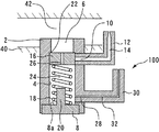
- the body 2 is formed with a cylinder 4 having an oil supply port 6 as an inlet.
- the cylinder 4 is formed through the body 2, and its outlet is covered with a plug 8. That is, the plug 8 constitutes the bottom of the cylinder 4.
- a space (a closed section 24 described later) in which one end is opened and the other end is closed is formed.
- An oil injection port 10 having a smaller diameter than that of the cylinder 4 is opened near the inlet of the side surface of the cylinder 4.
- a first oil injection nozzle 12 is attached to the body 2 by brazing or the like, and a first oil injection passage 14 formed in the first oil injection nozzle 12 is communicated with the oil injection port 10.
- the tip of the first oil injection passage 14 is narrowed so that the diameter decreases toward the passage outlet in order to increase the flow velocity of the oil flowing through the first oil injection passage 14.
- the tip of the first oil injection nozzle 12 is directed to the back surface of the piston of the internal combustion engine.
- a plurality of oil injection ports 10 are formed in the circumferential direction of the cylinder 4 to form a plurality of first oil injection nozzles 12. 2 can also be attached.
- the piston valve 16 is accommodated in the cylinder 4 so as to be reciprocally movable along the wall surface of the cylinder 4.
- the cylinder 4 houses a spring 18.
- the spring 18 is a coiled compression spring and is disposed between the piston valve 16 and the bottom surface of the cylinder 4 (reference surface 8a of the plug 8).
- the plug 8 is integrally formed with a stopper 20.
- the stopper 20 has a cylindrical shape, and projects into the cylinder 4 from the bottom of the cylinder 4 (relative to the reference surface 8 a of the plug 8) inside the spring 18.
- the movement range of the piston valve 16 is specified by restricting the downward movement by the stopper 20 and restricting the upward movement by the stepped portion 22 between the oil supply port 6 and the cylinder 4.
- the length of the spring 18 is adjusted so that the piston valve 16 comes into contact with the stepped portion 22 and closes the oil injection port 10 when no hydraulic pressure is applied to the piston valve 16.
- the height of the stopper 20 is set so that the later-described leak hole 28 is not blocked when the piston valve 16 moves downward.
- a closed section 24 surrounded by the piston valve 16 and the side surface and bottom of the cylinder 4 is formed.
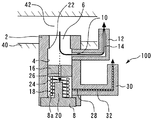
- the piston valve 16 is formed with an orifice 26 that allows the closed section 24 to communicate with the oil supply port 6 side. For this reason, when the oil jet 100 is attached to the cylinder block 40, the closed compartment 24 is filled with oil through the orifice 26.
- a differential pressure with respect to the hydraulic pressure of the oil passage 42 is generated in the hydraulic pressure of the closed section 24 by the configuration described below.
- the closed section 24 is referred to as a differential pressure chamber.
- the bottom of the differential pressure chamber 24 is formed by the plug 8.
- a leak hole 28 for allowing the oil in the differential pressure chamber 24 to leak out of the cylinder 4 is opened.
- the cross-sectional area of the leak hole 28 is significantly smaller than the cross-sectional area of the differential pressure chamber 24.
- the channel cross-sectional area of the leak hole 28 is formed smaller than the channel cross-sectional area of the orifice 26.
- a second oil injection nozzle 30 is attached to the body 2 by brazing or the like, and a first oil injection passage 32 formed in the first oil injection nozzle 30 is connected to a leak hole 28 (second oil injection port). As well as function).
- the tip of the second oil injection passage 32 is narrowed so that the diameter decreases toward the passage outlet in order to increase the flow velocity of the oil flowing in the second oil injection passage 32.
- the tip of the second oil injection nozzle 30 is directed to the cylinder bore of the internal combustion engine.
- a plurality of second oil injection nozzles 30 are formed in the body 2 by forming a plurality of leak holes 28 in the circumferential direction of the cylinder 4. It can also be attached to.
- the bottom portion (plug 8) of the closed cylinder 4 is located below the opening position of the leak hole 28 in the cylinder 4 in the gravity direction. More specifically, the leak hole 28 communicates with the differential pressure chamber 24 above the lowest position (reference surface 8a of the plug 8) in the vertical direction (gravity direction) of the differential pressure chamber 24. More specifically, the leak hole 28 is formed on the side surface of the cylinder 4 at a portion above the reference surface 8 a of the plug 8 and below the tip of the stopper 20. In addition, if the bottom part (stopper 20) of the cylinder 4 is positioned on the lower side in the gravity direction, it is not necessary that the central axis direction of the cylinder 4 and the gravity direction completely coincide with each other.
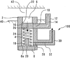
- the oil pressure of the oil flowing through the oil passage 42 acts on the piston valve 16 from the oil supply port 6 side.
- the hydraulic pressure in the differential pressure chamber 24 and the urging force of the spring 18 act on the piston valve 16 from opposite directions.
- the former acts as a force in the valve opening direction on the piston valve 16
- the latter acts as a force in the valve closing direction. Therefore, if the resultant force of the hydraulic pressure in the differential pressure chamber 24 and the biasing force of the spring 18 is equal to or greater than the force of the hydraulic pressure in the oil passage 42, the piston valve 16 is as shown in the schematic diagram of FIG.
- the oil injection port 10 is held at a position for closing.
- the piston valve 16 is maintained in a closed state.
- oil injection from the second oil injection nozzle 30 is achieved.
- the hydraulic pressure in the oil passage 42 required to open the piston valve 16 is determined by the hydraulic pressure in the differential pressure chamber 24.
- the oil pressure in the differential pressure chamber 24 varies depending on the relationship between the flow rate of oil entering the differential pressure chamber 24 and the flow rate of oil exiting the differential pressure chamber 24. Since oil flows into the differential pressure chamber 24 through the orifice 26, the flow rate Q1 is in accordance with Bernoulli's theorem as expressed by the following equation (1).
- the flow rate Q1 of the oil passing through the orifice 26 is proportional to the square of the differential pressure between the hydraulic pressure P M / G in the oil passage 42 and the hydraulic pressure P IN in the differential pressure chamber 24, and the oil density ⁇ is 1. / Inversely proportional to the square.
- C is a flow coefficient
- A is a cross-sectional area of the orifice 26.
- the size (diameter, width, etc.) of the orifice 26 is set so that it functions as a flow passage according to the Bernoulli theorem.
- the flow rate Q2 is in accordance with Hagen-Poiseuille's law as expressed by the following equation 2. That is, the flow rate Q2 of oil passing through the leak hole 28 is proportional to the differential pressure between the hydraulic pressure P IN and the atmospheric pressure P OUT in the differential pressure chamber 24, and inversely proportional to the oil viscosity ⁇ .
- B is a coefficient.
- the leak hole 28 and the second oil injection passage 32 communicating with the leak hole 28 are dimensioned so as to function as a flow path in accordance with the Hagen-Poiseuille law (the diameter and length of the flow path). Is set.
- the oil density affects the flow rate of the oil passing through the orifice 26, but the oil viscosity affects the flow rate of the oil passing through the leak hole 28.
- Oil density and oil viscosity are both affected by oil temperature, but their sensitivity differs greatly. Specifically, there is almost no change in the oil density with respect to the change in the oil temperature, and the oil density is substantially constant in the temperature range from cold to completion of warm-up. On the other hand, the change of the oil viscosity with respect to the change of the oil temperature is extremely large, and the oil viscosity in the cold state is about 20 times higher than the oil viscosity after the warm-up.
- the flow rate of oil flowing into the differential pressure chamber 24 from the orifice 26 does not vary greatly depending on the oil temperature, but the flow rate of oil leaking from the leak hole 28 is It increases with increasing temperature.
- the leak hole 28 Since the oil is difficult to leak from, the valve opening pressure becomes high.
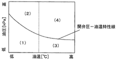
- the valve opening pressure-oil temperature characteristic of the oil jet 100 according to the present embodiment is represented by a graph in which the vertical axis indicates the hydraulic pressure and the horizontal axis indicates the oil temperature.
- the valve opening pressure is mechanically automatically adjusted such that the higher the oil temperature, the lower the oil temperature, and the higher the oil temperature.
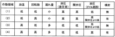
- the operating region of the oil jet 100 is divided into four regions depending on the oil temperature and the oil pressure.
- the operating area (1) is a low oil temperature and low oil pressure area. Since the hydraulic pressure changes in accordance with the rotational speed of the internal combustion engine, it can be said that the operation region (1) is a low oil temperature low rotation region. Since the oil viscosity is high at a low oil temperature, the oil that has flowed into the differential pressure chamber 24 through the orifice 26 is less likely to leak from the leak hole 28. Therefore, the hydraulic pressure in the differential pressure chamber 24 increases and the valve opening pressure of the piston valve 16 increases. Then, the piston valve 16 does not open in a low rotation range where the oil pressure in the oil passage 42 is low, and oil injection by the first oil injection nozzle 12 is not performed. When the internal combustion engine is in the operating region (1), cooling with oil is not required because the piston temperature of the internal combustion engine is low. Rather, piston overcooling can be prevented by stopping oil injection from the first oil injection nozzle 12.
- the operating region (2) is a low oil temperature high hydraulic pressure region, that is, a low oil temperature high rotation region. A situation where a cold internal combustion engine is operated at a high rotation speed corresponds to this region, and the temperature of the piston rises to a level that requires cooling.
- the piston valve 16 opens when the hydraulic pressure in the oil passage 42 exceeds the valve opening pressure, and the first oil injection nozzle 12 Oil injection is performed. Thereby, the piston which became high temperature can be cooled effectively.
- the operating region (3) is a high oil temperature and low oil pressure region, that is, a high oil temperature and low rotation region. Since the oil viscosity is low at a high oil temperature, the oil that has flowed into the differential pressure chamber 24 through the orifice 26 tends to leak from the leak hole 28. Accordingly, the hydraulic pressure in the differential pressure chamber 24 is lowered, and the valve opening pressure of the piston valve 16 is lowered. However, since the hydraulic pressure in the oil passage 42 is low in the low rotation range, the piston valve 16 does not open and oil injection by the first oil injection nozzle 12 is not performed. When the internal combustion engine is in the operating region (3), although the oil temperature is high, the temperature of the piston does not increase so much because the rotational speed is low. Therefore, it is not necessary to cool the piston with oil, but rather, the piston can be prevented from being overcooled by stopping the oil injection from the first oil injection nozzle 12.
- the operating region (4) is a high oil temperature high hydraulic pressure region, that is, a high oil temperature high rotation region.
- the oil pressure in the oil passage 42 is increased, but the oil is liable to leak from the leak hole 28 due to the decrease in the oil viscosity, and the valve opening pressure of the piston valve 16 is decreased. For this reason, the piston valve 16 is easily opened, the oil injection by the first oil injection nozzle 12 is performed, and the piston that has reached a high temperature is effectively cooled.
- the oil injection from the first oil injection nozzle 12 is reliably performed in the operation region where the piston of the internal combustion engine needs to be cooled, and the piston is cooled.
- the oil injection can be surely stopped in the unnecessary operation region.
- even if a failure occurs specifically, even when the spring 18 that operates the piston valve 16 is broken, the necessary oil injection is ensured. Can be done. That is, since the spring 18 urges the piston valve 16 in a direction to prevent the valve from opening, when the spring 18 is broken, the urging force is lost, and the piston valve 16 is opened by a lower hydraulic pressure. . According to this, since the oil is reliably injected to the piston, it is possible to prevent a malfunction such as seizure of the piston due to the failure of the oil jet 100.
- oil jet 100 there is a difference in the momentum of the injection due to the opening / closing of the piston valve 16 and the effect of the oil viscosity in any of the operation regions (1) to (4).
- oil injection is performed from the second oil injection nozzle 30 toward the cylinder bore.
- the oil leaking to the outside from the leak hole 28 provided for enabling the valve opening pressure to be automatically adjusted automatically according to the oil temperature is effectively used for lubricating the cylinder bore rather than merely leaking. become able to.
- the oil jet 100 constantly injects oil into the cylinder bore and the first oil injection nozzle 12 that injects oil to the back surface of the piston in the operation region where the piston of the internal combustion engine needs to be cooled. It can be said that the second oil injection nozzle 30 is provided.
- the leak hole 28 and the second oil injection nozzle 30 connected to the leak hole 28 are installed on the side surface of the cylinder 4.
- the foreign matter is directed toward the bottom of the cylinder 4 due to its own weight, so that the leak hole 28 can be less likely to be clogged with foreign matter.
- the oil injection from the second oil injection nozzle 30 for the cylinder bore can be stably performed.
- the foreign matter resistance can be improved with a simple structure without the need to install a foreign matter removing member such as a filter inside the oil jet 100.
- the second oil injection nozzle 30 is provided as one that injects oil toward the cylinder bore.
- the tip of the second injection nozzle in the present invention is not It may be directed.
Abstract
L'invention concerne un moyen (100) de projection d'huile dont le corps (2) est muni d'un orifice (6) d'alimentation en huile, d'un cylindre (4) et un orifice (10) de projection d'huile. Une soupape (16) à piston est logée à l'intérieur du cylindre (4). La soupape (16) à piston forme à l'intérieur du cylindre (4) une chambre (24) à pression différentielle qui est un espace fermé, et un orifice (26) servant à relier la chambre (24) à pression différentielle au côté orifice (6) d'alimentation en huile est formée dans la soupape (16) à piston. La soupape (16) à piston est pressée par un ressort (18) vers la position dans laquelle la soupape (16) à piston ferme l'orifice (10) de projection d'huile. Une première buse (12) de projection d'huile est reliée à l'orifice (10) de projection d'huile. Un trou (28) de fuite qui laisse de l'huile s'échapper de la chambre (24) à pression différentielle vers l'extérieur du cylindre (4) est pratiqué dans une surface latérale du cylindre (4). Une deuxième buse (30) de projection d'huile est reliée au trou (28) de fuite.
Priority Applications (3)
| Application Number | Priority Date | Filing Date | Title |
|---|---|---|---|
| EP14835261.0A EP3032055B1 (fr) | 2013-08-09 | 2014-06-09 | Moyen de projection d'huile |
| CN201480044704.7A CN105452619B (zh) | 2013-08-09 | 2014-06-09 | 喷油装置 |
| US14/910,857 US10233816B2 (en) | 2013-08-09 | 2014-06-09 | Oil jet |
Applications Claiming Priority (2)
| Application Number | Priority Date | Filing Date | Title |
|---|---|---|---|
| JP2013-166806 | 2013-08-09 | ||
| JP2013166806A JP6148111B2 (ja) | 2013-08-09 | 2013-08-09 | オイルジェット |
Publications (1)
| Publication Number | Publication Date |
|---|---|
| WO2015019697A1 true WO2015019697A1 (fr) | 2015-02-12 |
Family
ID=52461041
Family Applications (1)
| Application Number | Title | Priority Date | Filing Date |
|---|---|---|---|
| PCT/JP2014/065216 WO2015019697A1 (fr) | 2013-08-09 | 2014-06-09 | Moyen de projection d'huile |
Country Status (5)
| Country | Link |
|---|---|
| US (1) | US10233816B2 (fr) |
| EP (1) | EP3032055B1 (fr) |
| JP (1) | JP6148111B2 (fr) |
| CN (1) | CN105452619B (fr) |
| WO (1) | WO2015019697A1 (fr) |
Cited By (1)
| Publication number | Priority date | Publication date | Assignee | Title |
|---|---|---|---|---|
| US10590830B1 (en) * | 2018-10-23 | 2020-03-17 | GM Global Technology Operations LLC | Internal combustion engine including piston cooling jets |
Families Citing this family (15)
| Publication number | Priority date | Publication date | Assignee | Title |
|---|---|---|---|---|
| DE102014005364A1 (de) * | 2014-04-11 | 2015-10-29 | Mahle International Gmbh | Baueinheit aus einem Kolben und einer Ölspritzdüse für einen Verbrennungsmotor |
| CN105545443A (zh) * | 2015-12-31 | 2016-05-04 | 潍柴动力扬州柴油机有限责任公司 | 一种活塞冷却喷嘴 |
| CN106091010B (zh) * | 2016-06-21 | 2019-03-08 | 中国航空工业集团公司沈阳发动机设计研究所 | 一种发动机燃烧室双油路喷嘴活门 |
| CN106285895A (zh) * | 2016-08-29 | 2017-01-04 | 潍柴动力股份有限公司 | 一种发动机及活塞冷却喷嘴总成 |
| DE102016219857A1 (de) * | 2016-10-12 | 2018-04-12 | Bayerische Motoren Werke Aktiengesellschaft | Vorrichtung zur Kühlung eines Kolbens einer Hubkolben-Brennkraftmaschine |
| DE102016221353A1 (de) * | 2016-10-28 | 2018-05-03 | Mahle International Gmbh | Brennkraftmaschine |
| AT519000B1 (de) * | 2016-10-31 | 2018-03-15 | Avl List Gmbh | Brennkraftmaschine |
| DE102017201905B4 (de) | 2017-02-07 | 2022-05-05 | Wagner Gmbh & Co. Kg | Steuerventil für Düsen und Düsenkopf mit dem Steuerventil |
| DE102017212547A1 (de) * | 2017-07-21 | 2019-01-24 | Bayerische Motoren Werke Aktiengesellschaft | Hubkolben-Brennkraftmaschine |
| DE102017123664A1 (de) * | 2017-10-11 | 2019-04-11 | Man Truck & Bus Ag | Ventil zum Einstellen eines Kühlfluidflusses zur Kolbenkühlung |
| US11248515B2 (en) * | 2019-08-02 | 2022-02-15 | Transportation Ip Holdings, Llc | Piston cooling jet system |
| DE102020208867A1 (de) * | 2020-07-16 | 2022-01-20 | Volkswagen Aktiengesellschaft | Diagnoseverfahren für ein Kolbenkühldüsenventil, Diagnosevorrichtung, Steuergerät, Kraftfahrzeug |
| CN112031910A (zh) * | 2020-09-30 | 2020-12-04 | 广西玉柴机器股份有限公司 | 一种分级开启的喷钩布置方法及结构 |
| KR20220159159A (ko) * | 2021-05-25 | 2022-12-02 | 현대자동차주식회사 | 엔진의 피스톤 쿨링 장치 및 그 제어 방법 |
| KR20230021912A (ko) * | 2021-08-06 | 2023-02-14 | 현대자동차주식회사 | Pcj 솔레노이드밸브 진단 방법 |
Citations (5)
| Publication number | Priority date | Publication date | Assignee | Title |
|---|---|---|---|---|
| JPH0642346A (ja) | 1992-07-22 | 1994-02-15 | Nissan Motor Co Ltd | 内燃機関のピストン冷却装置 |
| JP2006138307A (ja) * | 2004-10-15 | 2006-06-01 | Toyota Motor Corp | 内燃機関の潤滑装置 |
| JP2011012650A (ja) | 2009-07-06 | 2011-01-20 | Matsumoto Jukogyo Kk | オイルジェット |
| JP2011064155A (ja) | 2009-09-18 | 2011-03-31 | Hitachi Automotive Systems Ltd | 内燃機関用ピストンの冷却装置 |
| US20130019834A1 (en) * | 2011-07-20 | 2013-01-24 | GM Global Technology Operations LLC | Oil squirter |
Family Cites Families (35)
| Publication number | Priority date | Publication date | Assignee | Title |
|---|---|---|---|---|
| DE2546273C2 (de) * | 1975-10-16 | 1984-11-22 | Audi Nsu Auto Union Ag, 7107 Neckarsulm | Vorrichtung zur Regelung der Kolbenölkühlung für eine Kolbenbrennkraftmaschine |
| US4206726A (en) * | 1977-07-18 | 1980-06-10 | Caterpillar Tractor Co. | Double orifice piston cooling nozzle for reciprocating engines |
| US4276960A (en) * | 1979-05-17 | 1981-07-07 | Ingersoll-Rand Company | Oil distributing means |
| US4508065A (en) * | 1983-03-21 | 1985-04-02 | General Motors Corporation | Piston cooling oil delivery tube assembly |
| JPS61138816A (ja) * | 1984-12-07 | 1986-06-26 | Toyota Motor Corp | 直噴式内燃機関の燃料蒸発率制御装置 |
| JPH04121457A (ja) * | 1990-09-11 | 1992-04-22 | Zexel Corp | 自動変速装置付車輛のエンジン始動装置 |
| JP3447782B2 (ja) * | 1993-01-19 | 2003-09-16 | トヨタ自動車株式会社 | 内燃機関の潤滑装置 |
| JP3106058B2 (ja) * | 1994-05-20 | 2000-11-06 | 株式会社ユニシアジェックス | 内燃機関における潤滑・冷却装置 |
| JP3161282B2 (ja) | 1995-05-31 | 2001-04-25 | 日産自動車株式会社 | 内燃機関のピストン冷却装置 |
| DE19633167A1 (de) * | 1996-08-17 | 1998-02-19 | Porsche Ag | Spritzdüse für die Kolbenkühlung einer Brennkraftmaschine |
| US5819692A (en) * | 1997-05-01 | 1998-10-13 | Schafer; Timothy Vernon | Piston cooling oil control valve |
| DE19943516B4 (de) * | 1999-09-11 | 2017-01-19 | Schaeffler Technologies AG & Co. KG | Düsenventil |
| US6488479B1 (en) * | 2001-05-17 | 2002-12-03 | Ford Global Technologies, Inc. | Variable pressure oil pump |
| FR2827009B1 (fr) * | 2001-07-04 | 2003-12-12 | Bontaz Centre Sa | Gicleur de refroidissement a piston |
| FR2844003B1 (fr) * | 2002-09-02 | 2006-06-16 | Bontaz Centre Sa | Gicleur a projections multiples pour refroidissement de moteur, et moteurs equipes de tels gicleurs |
| GB2403852B (en) * | 2003-07-07 | 2006-05-31 | Electrolux Outdoor Prod Ltd | Starter |
| US7152623B2 (en) * | 2003-09-09 | 2006-12-26 | Metaldyne Company, Llc | Fluid jet for providing fluid under pressure to a desired location |
| FR2859756B1 (fr) * | 2003-09-16 | 2007-09-21 | Bontaz Centre Sa | Dispositif de refroidissement pour pistons de moteur. |
| DE102005043232A1 (de) * | 2005-09-09 | 2007-03-15 | Bayerische Motoren Werke Ag | Vorrichtung zum Starten des Motors eines Kraftfahrzeugs |
| JP2007113460A (ja) * | 2005-10-19 | 2007-05-10 | Nissan Motor Co Ltd | エンジン始動制御装置およびエンジン始動制御方法。 |
| JP4333690B2 (ja) * | 2006-05-12 | 2009-09-16 | 株式会社デンソー | エンジン始動制御システム |
| DE102009006963A1 (de) * | 2009-01-31 | 2010-08-05 | Dr. Ing. H.C. F. Porsche Aktiengesellschaft | Ölversorgungseinrichtung |
| JP2011012619A (ja) * | 2009-07-03 | 2011-01-20 | Matsumoto Jukogyo Kk | オイルジェット |
| US8171907B2 (en) * | 2009-11-19 | 2012-05-08 | Briggs And Stratton Corporation | Push button starting system for outdoor power equipment |
| JP5827164B2 (ja) * | 2012-04-04 | 2015-12-02 | トヨタ自動車株式会社 | オイルジェット |
| JP5680601B2 (ja) | 2012-09-29 | 2015-03-04 | 大豊工業株式会社 | ピストンクーリングジェット |
| JP6011518B2 (ja) * | 2013-11-21 | 2016-10-19 | トヨタ自動車株式会社 | 車両用制御装置、制御方法 |
| JP6171917B2 (ja) * | 2013-12-18 | 2017-08-02 | 株式会社デンソー | エンジン始動装置 |
| US9404466B2 (en) * | 2014-06-14 | 2016-08-02 | GM Global Technology Operations LLC | Method for evaluating an engine starting system |
| US9401053B2 (en) * | 2014-09-09 | 2016-07-26 | GM Global Technology Operations LLC | Fault notifications for vehicles |
| US9790910B2 (en) * | 2015-01-13 | 2017-10-17 | Toyota Motor Engineering & Manufacturing North America, Inc. | System and method for preventing unwanted engine restarts while parking a vehicle |
| JP2016194270A (ja) * | 2015-03-31 | 2016-11-17 | トヨタ自動車株式会社 | エンジン自動制御装置 |
| JP2016200051A (ja) * | 2015-04-09 | 2016-12-01 | トヨタ自動車株式会社 | エンジン始動制御装置 |
| US9758171B2 (en) * | 2015-06-15 | 2017-09-12 | GM Global Technology Operations LLC | Method and apparatus for controlling a multi-mode powertrain system including an engine having stop/start capability |
| US9951704B2 (en) * | 2015-09-08 | 2018-04-24 | GM Global Technology Operations LLC | No start event monitoring |
-
2013
- 2013-08-09 JP JP2013166806A patent/JP6148111B2/ja not_active Expired - Fee Related
-
2014
- 2014-06-09 EP EP14835261.0A patent/EP3032055B1/fr active Active
- 2014-06-09 WO PCT/JP2014/065216 patent/WO2015019697A1/fr active Application Filing
- 2014-06-09 US US14/910,857 patent/US10233816B2/en active Active
- 2014-06-09 CN CN201480044704.7A patent/CN105452619B/zh active Active
Patent Citations (5)
| Publication number | Priority date | Publication date | Assignee | Title |
|---|---|---|---|---|
| JPH0642346A (ja) | 1992-07-22 | 1994-02-15 | Nissan Motor Co Ltd | 内燃機関のピストン冷却装置 |
| JP2006138307A (ja) * | 2004-10-15 | 2006-06-01 | Toyota Motor Corp | 内燃機関の潤滑装置 |
| JP2011012650A (ja) | 2009-07-06 | 2011-01-20 | Matsumoto Jukogyo Kk | オイルジェット |
| JP2011064155A (ja) | 2009-09-18 | 2011-03-31 | Hitachi Automotive Systems Ltd | 内燃機関用ピストンの冷却装置 |
| US20130019834A1 (en) * | 2011-07-20 | 2013-01-24 | GM Global Technology Operations LLC | Oil squirter |
Cited By (1)
| Publication number | Priority date | Publication date | Assignee | Title |
|---|---|---|---|---|
| US10590830B1 (en) * | 2018-10-23 | 2020-03-17 | GM Global Technology Operations LLC | Internal combustion engine including piston cooling jets |
Also Published As
| Publication number | Publication date |
|---|---|
| EP3032055B1 (fr) | 2018-01-10 |
| US10233816B2 (en) | 2019-03-19 |
| EP3032055A4 (fr) | 2017-02-01 |
| JP6148111B2 (ja) | 2017-06-14 |
| JP2015034537A (ja) | 2015-02-19 |
| EP3032055A1 (fr) | 2016-06-15 |
| US20160186642A1 (en) | 2016-06-30 |
| CN105452619A (zh) | 2016-03-30 |
| CN105452619B (zh) | 2018-03-06 |
Similar Documents
| Publication | Publication Date | Title |
|---|---|---|
| JP6148111B2 (ja) | オイルジェット | |
| JP5827164B2 (ja) | オイルジェット | |
| JP5680601B2 (ja) | ピストンクーリングジェット | |
| JP2015034537A5 (fr) | ||
| JP2006312936A (ja) | ピストン冷却ノズルの制御された漏出バルブ | |
| US9382821B2 (en) | Biased normally open check valve assembly | |
| JP2007505281A (ja) | 目標箇所に加圧流体を供給するための流体ジェット | |
| JP4381341B2 (ja) | ピストンの冷却装置 | |
| FI117643B (fi) | Järjestely polttoaineen syöttölaitteistossa | |
| JP2013217202A (ja) | オイルジェット | |
| JP3832401B2 (ja) | 燃料噴射装置 | |
| JP5526194B2 (ja) | ターボ過給型大型2サイクルディーゼルエンジン用の燃料弁 | |
| US10774726B2 (en) | Valve for adjusting a cooling fluid flow for piston cooling | |
| JP2013249742A (ja) | オイルジェット | |
| JP2014009603A (ja) | オイルジェット | |
| JP2006283603A (ja) | 内燃機関のピストン冷却装置 | |
| RU2679957C1 (ru) | Форсунка, двигатель, снабженный форсункой, и транспортное средство | |
| CS234514B1 (en) | Equipment for piston spraying by oil | |
| CN114174650B (zh) | 实现低速热运行保护的被动活塞冷却喷嘴控制 | |
| RU2777178C2 (ru) | Клапан регулировки потока охлаждающей среды для охлаждения поршней | |
| JP2019148231A (ja) | オイルジェット装置 | |
| US20190048992A1 (en) | System for controlling a vehicle transmission sump fluid level | |
| JP2014070610A (ja) | ピストンクーリングジェット | |
| JP2015004303A (ja) | 油量調整装置 | |
| KR101461907B1 (ko) | 가변 오리피스 및 이를 포함하는 가변 밸브 리프트 시스템 |
Legal Events
| Date | Code | Title | Description |
|---|---|---|---|
| WWE | Wipo information: entry into national phase |
Ref document number: 201480044704.7 Country of ref document: CN |
|
| 121 | Ep: the epo has been informed by wipo that ep was designated in this application |
Ref document number: 14835261 Country of ref document: EP Kind code of ref document: A1 |
|
| WWE | Wipo information: entry into national phase |
Ref document number: 14910857 Country of ref document: US |
|
| NENP | Non-entry into the national phase |
Ref country code: DE |
|
| WWE | Wipo information: entry into national phase |
Ref document number: 2014835261 Country of ref document: EP |