WO2015019697A1 - Oil jet - Google Patents
Oil jet Download PDFInfo
- Publication number
- WO2015019697A1 WO2015019697A1 PCT/JP2014/065216 JP2014065216W WO2015019697A1 WO 2015019697 A1 WO2015019697 A1 WO 2015019697A1 JP 2014065216 W JP2014065216 W JP 2014065216W WO 2015019697 A1 WO2015019697 A1 WO 2015019697A1
- Authority
- WO
- WIPO (PCT)
- Prior art keywords
- oil
- cylinder
- valve
- oil injection
- piston
- Prior art date
Links
Images
Classifications
-
- F—MECHANICAL ENGINEERING; LIGHTING; HEATING; WEAPONS; BLASTING
- F01—MACHINES OR ENGINES IN GENERAL; ENGINE PLANTS IN GENERAL; STEAM ENGINES
- F01P—COOLING OF MACHINES OR ENGINES IN GENERAL; COOLING OF INTERNAL-COMBUSTION ENGINES
- F01P3/00—Liquid cooling
- F01P3/06—Arrangements for cooling pistons
- F01P3/08—Cooling of piston exterior only, e.g. by jets
-
- F—MECHANICAL ENGINEERING; LIGHTING; HEATING; WEAPONS; BLASTING
- F01—MACHINES OR ENGINES IN GENERAL; ENGINE PLANTS IN GENERAL; STEAM ENGINES
- F01M—LUBRICATING OF MACHINES OR ENGINES IN GENERAL; LUBRICATING INTERNAL COMBUSTION ENGINES; CRANKCASE VENTILATING
- F01M1/00—Pressure lubrication
- F01M1/08—Lubricating systems characterised by the provision therein of lubricant jetting means
- F01M2001/083—Lubricating systems characterised by the provision therein of lubricant jetting means for lubricating cylinders
Definitions
- the present invention relates to an oil jet used for cooling a piston of an internal combustion engine.
- the oil jet is a device that injects oil supplied from the oil passage between the piston and the piston and the cylinder bore, thereby cooling the piston in a high temperature state.
- Conventionally used oil jets have a mechanism for opening and closing a valve in accordance with hydraulic pressure. Specifically, the valve body is biased by a spring in a direction against the hydraulic pressure, and when the force received by the hydraulic pressure exceeds the force of the spring, the valve body separates from the valve seat and the valve opens. It is like that. While the hydraulic pressure increases as the rotational speed of the internal combustion engine increases, the piston temperature increases as the rotational speed increases. Therefore, according to the above mechanism, oil is injected to cool the piston while the piston is hot. In a situation where the temperature of the piston is not high, overcooling can be prevented by stopping oil injection.
- an oil jet having a mechanism for opening and closing the valve according to the oil temperature has also been proposed.
- the oil jet described in the following Patent Document 2 has a first mechanism for opening and closing a valve with a normal spring and a second mechanism for opening and closing a valve with a spring made of a shape memory alloy.
- the first mechanism having a normal spring the valve element opens when the force received from the hydraulic pressure exceeds the force of the spring.
- the second mechanism having a spring made of a shape memory alloy the valve is closed when the spring is contracted when cold, and the valve is opened when the spring is restored and extended when warm. According to such a mechanism, both valves are opened and oil is injected only when the hydraulic pressure is high and the temperature of the oil is high.
- Each oil jet described in Patent Documents 1 and 2 is configured so that its operating state changes not only by oil pressure but also by oil temperature. Since the oil temperature is closely related to the temperature state of the piston as well as the oil pressure, the configuration in which the operating state of the oil jet is switched according to the oil temperature is a general oil that simply opens and closes the valve according to the oil pressure. It is considered that the piston can be cooled more appropriately by the injection of oil than the jet.
- valve opening pressure when the valve opens according to the oil temperature.
- the valve opening pressure is mechanically automatically adjusted instead of electrically operating the opening and closing of the valve as in the oil jet described in Patent Document 3. This is because it is advantageous in terms of reliability and cost.
- the oil used can be used effectively.
- the present invention has been made in view of such a problem, and provides an oil jet in which the valve opening pressure is mechanically automatically adjusted according to the oil temperature while effectively using the supplied oil. With the goal.
- the oil jet according to the present invention includes at least a body, a piston valve, a spring, a first oil injection nozzle, and a second oil injection nozzle.
- the body is an oil jet main body attached to a cylinder block of the internal combustion engine, and has an oil supply port, a cylinder, and an oil injection port.
- the oil supply port is formed so as to open to an oil passage in the cylinder block when the body is attached to the cylinder block.
- One end of the cylinder communicates with the oil supply port and the other end is closed.
- the oil injection port opens on the side of the cylinder.
- the piston valve is accommodated in the cylinder to form a closed compartment in the cylinder.
- the piston valve is formed with an orifice that allows the closed section to communicate with the oil supply port.
- the spring urges the piston valve to a position that closes the oil injection port.
- the first oil injection nozzle is connected to the oil injection port and adjusts the direction of oil injection.
- a leak hole for allowing oil to leak from the closed section to the outside of the cylinder is opened on the side surface of the cylinder.
- the oil jet according to the present invention further includes a second oil injection nozzle that is connected to the leak hole and adjusts the direction of oil injection.
- the oil injection port is opened and closed by the piston valve.
- the pressure of the oil flowing through the oil passage in the cylinder block acts, and at the same time, the pressure of the oil in the closed compartment and the biasing force of the spring act in the opposite direction.
- the piston valve is supplied from the oil passage when the force received by the piston valve from the oil pressure in the oil passage is larger than the resultant force of the force received by the piston valve from the oil pressure in the closed compartment and the biasing force by the spring. Moves from the position where it is pushed by oil and closes the oil injection port. As a result, the piston valve is opened, the oil injection port communicates with the oil supply port, and oil is supplied to the oil injection port to achieve the injection of oil from the first oil injection nozzle.
- the hydraulic pressure in the closed compartment changes depending on the relationship between the flow rate of oil flowing into the closed compartment through the orifice and the flow rate of oil leaking from the closed compartment through the leak hole.
- the orifice and the leak hole are different in factors that determine the flow rate.
- the oil density affects the flow. More specifically, the flow rate of the oil that passes through the orifice and flows into the closed section from the oil injection port side is inversely proportional to the 1/2 power of the oil density.
- the oil viscosity affects the flow rate.
- the flow rate of oil that passes through the leak hole and leaks from the closed section of the cylinder to the outside of the body is inversely proportional to the oil viscosity.
- the sensitivity to oil temperature differs greatly between oil density and oil viscosity.
- the oil density can be regarded as almost constant in the normal temperature range of the oil in the internal combustion engine.
- the change in oil viscosity with respect to the change in oil temperature is extremely large.
- the oil viscosity during cold is 10 times or more higher than the oil viscosity after warm-up.
- the valve opening pressure is determined by the oil pressure in the closed compartment.
- the oil temperature is high, such as after the warm-up is completed, the oil viscosity is low, so that oil easily leaks from the closed compartment, and as a result, the valve opening pressure becomes low because the pressure in the closed compartment becomes low.
- the oil temperature is low as in the cold state, the oil viscosity is high, so that the oil does not easily leak from the closed compartment, and as a result, the pressure in the closed compartment increases and the valve opening pressure also increases. That is, according to the configuration of the oil jet according to the present invention, the valve opening pressure is mechanically automatically adjusted so that the valve opening pressure is lower as the oil temperature is higher and the valve opening pressure is higher as the oil temperature is lower.
- oil injection from the 2nd oil injection nozzle is achieved using oil which leaks through a leak hole, irrespective of the opening-and-closing state of a piston valve.
- the other end of the closed cylinder may be located on the lower side in the gravity direction of the cylinder.
- the tip of the first oil injection nozzle may be directed to the back surface of the piston that reciprocates in the cylinder of the internal combustion engine
- the tip of the second oil injection nozzle may be directed to the cylinder bore of the internal combustion engine. Good.
- the valve opening pressure can be automatically and mechanically adjusted according to the oil temperature while effectively using the supplied oil.
- Embodiment 1 FIG. Embodiment 1 of the present invention will be described below with reference to the drawings.
- the body 2 is formed with a cylinder 4 having an oil supply port 6 as an inlet.
- the cylinder 4 is formed through the body 2, and its outlet is covered with a plug 8. That is, the plug 8 constitutes the bottom of the cylinder 4.
- a space (a closed section 24 described later) in which one end is opened and the other end is closed is formed.
- An oil injection port 10 having a smaller diameter than that of the cylinder 4 is opened near the inlet of the side surface of the cylinder 4.
- a first oil injection nozzle 12 is attached to the body 2 by brazing or the like, and a first oil injection passage 14 formed in the first oil injection nozzle 12 is communicated with the oil injection port 10.
- the tip of the first oil injection passage 14 is narrowed so that the diameter decreases toward the passage outlet in order to increase the flow velocity of the oil flowing through the first oil injection passage 14.
- the tip of the first oil injection nozzle 12 is directed to the back surface of the piston of the internal combustion engine.
- a plurality of oil injection ports 10 are formed in the circumferential direction of the cylinder 4 to form a plurality of first oil injection nozzles 12. 2 can also be attached.
- the piston valve 16 is accommodated in the cylinder 4 so as to be reciprocally movable along the wall surface of the cylinder 4.
- the cylinder 4 houses a spring 18.
- the spring 18 is a coiled compression spring and is disposed between the piston valve 16 and the bottom surface of the cylinder 4 (reference surface 8a of the plug 8).
- the plug 8 is integrally formed with a stopper 20.
- the stopper 20 has a cylindrical shape, and projects into the cylinder 4 from the bottom of the cylinder 4 (relative to the reference surface 8 a of the plug 8) inside the spring 18.
- the movement range of the piston valve 16 is specified by restricting the downward movement by the stopper 20 and restricting the upward movement by the stepped portion 22 between the oil supply port 6 and the cylinder 4.
- the length of the spring 18 is adjusted so that the piston valve 16 comes into contact with the stepped portion 22 and closes the oil injection port 10 when no hydraulic pressure is applied to the piston valve 16.
- the height of the stopper 20 is set so that the later-described leak hole 28 is not blocked when the piston valve 16 moves downward.
- a closed section 24 surrounded by the piston valve 16 and the side surface and bottom of the cylinder 4 is formed.
- the piston valve 16 is formed with an orifice 26 that allows the closed section 24 to communicate with the oil supply port 6 side. For this reason, when the oil jet 100 is attached to the cylinder block 40, the closed compartment 24 is filled with oil through the orifice 26.
- a differential pressure with respect to the hydraulic pressure of the oil passage 42 is generated in the hydraulic pressure of the closed section 24 by the configuration described below.
- the closed section 24 is referred to as a differential pressure chamber.
- the bottom of the differential pressure chamber 24 is formed by the plug 8.
- a leak hole 28 for allowing the oil in the differential pressure chamber 24 to leak out of the cylinder 4 is opened.
- the cross-sectional area of the leak hole 28 is significantly smaller than the cross-sectional area of the differential pressure chamber 24.
- the channel cross-sectional area of the leak hole 28 is formed smaller than the channel cross-sectional area of the orifice 26.
- a second oil injection nozzle 30 is attached to the body 2 by brazing or the like, and a first oil injection passage 32 formed in the first oil injection nozzle 30 is connected to a leak hole 28 (second oil injection port). As well as function).
- the tip of the second oil injection passage 32 is narrowed so that the diameter decreases toward the passage outlet in order to increase the flow velocity of the oil flowing in the second oil injection passage 32.
- the tip of the second oil injection nozzle 30 is directed to the cylinder bore of the internal combustion engine.
- a plurality of second oil injection nozzles 30 are formed in the body 2 by forming a plurality of leak holes 28 in the circumferential direction of the cylinder 4. It can also be attached to.
- the bottom portion (plug 8) of the closed cylinder 4 is located below the opening position of the leak hole 28 in the cylinder 4 in the gravity direction. More specifically, the leak hole 28 communicates with the differential pressure chamber 24 above the lowest position (reference surface 8a of the plug 8) in the vertical direction (gravity direction) of the differential pressure chamber 24. More specifically, the leak hole 28 is formed on the side surface of the cylinder 4 at a portion above the reference surface 8 a of the plug 8 and below the tip of the stopper 20. In addition, if the bottom part (stopper 20) of the cylinder 4 is positioned on the lower side in the gravity direction, it is not necessary that the central axis direction of the cylinder 4 and the gravity direction completely coincide with each other.
- the oil pressure of the oil flowing through the oil passage 42 acts on the piston valve 16 from the oil supply port 6 side.
- the hydraulic pressure in the differential pressure chamber 24 and the urging force of the spring 18 act on the piston valve 16 from opposite directions.
- the former acts as a force in the valve opening direction on the piston valve 16
- the latter acts as a force in the valve closing direction. Therefore, if the resultant force of the hydraulic pressure in the differential pressure chamber 24 and the biasing force of the spring 18 is equal to or greater than the force of the hydraulic pressure in the oil passage 42, the piston valve 16 is as shown in the schematic diagram of FIG.
- the oil injection port 10 is held at a position for closing.
- the piston valve 16 is maintained in a closed state.
- oil injection from the second oil injection nozzle 30 is achieved.
- the hydraulic pressure in the oil passage 42 required to open the piston valve 16 is determined by the hydraulic pressure in the differential pressure chamber 24.
- the oil pressure in the differential pressure chamber 24 varies depending on the relationship between the flow rate of oil entering the differential pressure chamber 24 and the flow rate of oil exiting the differential pressure chamber 24. Since oil flows into the differential pressure chamber 24 through the orifice 26, the flow rate Q1 is in accordance with Bernoulli's theorem as expressed by the following equation (1).
- the flow rate Q1 of the oil passing through the orifice 26 is proportional to the square of the differential pressure between the hydraulic pressure P M / G in the oil passage 42 and the hydraulic pressure P IN in the differential pressure chamber 24, and the oil density ⁇ is 1. / Inversely proportional to the square.
- C is a flow coefficient
- A is a cross-sectional area of the orifice 26.
- the size (diameter, width, etc.) of the orifice 26 is set so that it functions as a flow passage according to the Bernoulli theorem.
- the flow rate Q2 is in accordance with Hagen-Poiseuille's law as expressed by the following equation 2. That is, the flow rate Q2 of oil passing through the leak hole 28 is proportional to the differential pressure between the hydraulic pressure P IN and the atmospheric pressure P OUT in the differential pressure chamber 24, and inversely proportional to the oil viscosity ⁇ .
- B is a coefficient.
- the leak hole 28 and the second oil injection passage 32 communicating with the leak hole 28 are dimensioned so as to function as a flow path in accordance with the Hagen-Poiseuille law (the diameter and length of the flow path). Is set.
- the oil density affects the flow rate of the oil passing through the orifice 26, but the oil viscosity affects the flow rate of the oil passing through the leak hole 28.
- Oil density and oil viscosity are both affected by oil temperature, but their sensitivity differs greatly. Specifically, there is almost no change in the oil density with respect to the change in the oil temperature, and the oil density is substantially constant in the temperature range from cold to completion of warm-up. On the other hand, the change of the oil viscosity with respect to the change of the oil temperature is extremely large, and the oil viscosity in the cold state is about 20 times higher than the oil viscosity after the warm-up.
- the flow rate of oil flowing into the differential pressure chamber 24 from the orifice 26 does not vary greatly depending on the oil temperature, but the flow rate of oil leaking from the leak hole 28 is It increases with increasing temperature.
- the leak hole 28 Since the oil is difficult to leak from, the valve opening pressure becomes high.
- the valve opening pressure-oil temperature characteristic of the oil jet 100 according to the present embodiment is represented by a graph in which the vertical axis indicates the hydraulic pressure and the horizontal axis indicates the oil temperature.
- the valve opening pressure is mechanically automatically adjusted such that the higher the oil temperature, the lower the oil temperature, and the higher the oil temperature.
- the operating region of the oil jet 100 is divided into four regions depending on the oil temperature and the oil pressure.
- the operating area (1) is a low oil temperature and low oil pressure area. Since the hydraulic pressure changes in accordance with the rotational speed of the internal combustion engine, it can be said that the operation region (1) is a low oil temperature low rotation region. Since the oil viscosity is high at a low oil temperature, the oil that has flowed into the differential pressure chamber 24 through the orifice 26 is less likely to leak from the leak hole 28. Therefore, the hydraulic pressure in the differential pressure chamber 24 increases and the valve opening pressure of the piston valve 16 increases. Then, the piston valve 16 does not open in a low rotation range where the oil pressure in the oil passage 42 is low, and oil injection by the first oil injection nozzle 12 is not performed. When the internal combustion engine is in the operating region (1), cooling with oil is not required because the piston temperature of the internal combustion engine is low. Rather, piston overcooling can be prevented by stopping oil injection from the first oil injection nozzle 12.
- the operating region (2) is a low oil temperature high hydraulic pressure region, that is, a low oil temperature high rotation region. A situation where a cold internal combustion engine is operated at a high rotation speed corresponds to this region, and the temperature of the piston rises to a level that requires cooling.
- the piston valve 16 opens when the hydraulic pressure in the oil passage 42 exceeds the valve opening pressure, and the first oil injection nozzle 12 Oil injection is performed. Thereby, the piston which became high temperature can be cooled effectively.
- the operating region (3) is a high oil temperature and low oil pressure region, that is, a high oil temperature and low rotation region. Since the oil viscosity is low at a high oil temperature, the oil that has flowed into the differential pressure chamber 24 through the orifice 26 tends to leak from the leak hole 28. Accordingly, the hydraulic pressure in the differential pressure chamber 24 is lowered, and the valve opening pressure of the piston valve 16 is lowered. However, since the hydraulic pressure in the oil passage 42 is low in the low rotation range, the piston valve 16 does not open and oil injection by the first oil injection nozzle 12 is not performed. When the internal combustion engine is in the operating region (3), although the oil temperature is high, the temperature of the piston does not increase so much because the rotational speed is low. Therefore, it is not necessary to cool the piston with oil, but rather, the piston can be prevented from being overcooled by stopping the oil injection from the first oil injection nozzle 12.
- the operating region (4) is a high oil temperature high hydraulic pressure region, that is, a high oil temperature high rotation region.
- the oil pressure in the oil passage 42 is increased, but the oil is liable to leak from the leak hole 28 due to the decrease in the oil viscosity, and the valve opening pressure of the piston valve 16 is decreased. For this reason, the piston valve 16 is easily opened, the oil injection by the first oil injection nozzle 12 is performed, and the piston that has reached a high temperature is effectively cooled.
- the oil injection from the first oil injection nozzle 12 is reliably performed in the operation region where the piston of the internal combustion engine needs to be cooled, and the piston is cooled.
- the oil injection can be surely stopped in the unnecessary operation region.
- even if a failure occurs specifically, even when the spring 18 that operates the piston valve 16 is broken, the necessary oil injection is ensured. Can be done. That is, since the spring 18 urges the piston valve 16 in a direction to prevent the valve from opening, when the spring 18 is broken, the urging force is lost, and the piston valve 16 is opened by a lower hydraulic pressure. . According to this, since the oil is reliably injected to the piston, it is possible to prevent a malfunction such as seizure of the piston due to the failure of the oil jet 100.
- oil jet 100 there is a difference in the momentum of the injection due to the opening / closing of the piston valve 16 and the effect of the oil viscosity in any of the operation regions (1) to (4).
- oil injection is performed from the second oil injection nozzle 30 toward the cylinder bore.
- the oil leaking to the outside from the leak hole 28 provided for enabling the valve opening pressure to be automatically adjusted automatically according to the oil temperature is effectively used for lubricating the cylinder bore rather than merely leaking. become able to.
- the oil jet 100 constantly injects oil into the cylinder bore and the first oil injection nozzle 12 that injects oil to the back surface of the piston in the operation region where the piston of the internal combustion engine needs to be cooled. It can be said that the second oil injection nozzle 30 is provided.
- the leak hole 28 and the second oil injection nozzle 30 connected to the leak hole 28 are installed on the side surface of the cylinder 4.
- the foreign matter is directed toward the bottom of the cylinder 4 due to its own weight, so that the leak hole 28 can be less likely to be clogged with foreign matter.
- the oil injection from the second oil injection nozzle 30 for the cylinder bore can be stably performed.
- the foreign matter resistance can be improved with a simple structure without the need to install a foreign matter removing member such as a filter inside the oil jet 100.
- the second oil injection nozzle 30 is provided as one that injects oil toward the cylinder bore.
- the tip of the second injection nozzle in the present invention is not It may be directed.
Abstract
The body (2) of an oil jet (100) is provided with an oil supply port (6), a cylinder (4), and an oil jet port (10). A piston valve (16) is housed within the cylinder (4). The piston valve (16) forms within the cylinder (4) a differential pressure chamber (24) which is a closed space, and an orifice (26) for connecting the differential pressure chamber (24) to the oil supply port (6) side is formed in the piston valve (16). The piston valve (16) is pressed by a spring (18) to the position at which the piston valve (16) closes the oil jet port (10). A first oil jet nozzle (12) is connected to the oil jet port (10). A leakage hole (28) which allows oil to leak from the differential pressure chamber (24) to the outside of the cylinder (4) is open at a side surface of the cylinder (4). A second oil jet nozzle (30) is connected to the leakage hole (28).
Description
本発明は、内燃機関のピストンの冷却に用いられるオイルジェットに関する。
The present invention relates to an oil jet used for cooling a piston of an internal combustion engine.
内燃機関のシリンダブロックには、加圧されたオイルが流れるオイル通路が形成されている。オイルジェットはこのオイル通路から供給されるオイルをピストンやピストンとシリンダボアとの間に噴射し、それにより高温状態のピストンを冷却する装置である。従来一般的に用いられているオイルジェットは、油圧に応じて弁を開閉させる仕組みを有している。具体的には、弁体はバネによって油圧に抗する方向に付勢されており、弁体が油圧により受ける力がバネの力を上回ったときに、弁体が弁座から離れて弁が開くようになっている。油圧は内燃機関の回転数の上昇に応じて増大する一方、回転数が高まるほどピストンの温度も高くなることから、上記仕組みによればピストンが高温になる状況でオイルを噴射してピストンを冷却し、ピストンの温度が高くない状況ではオイルの噴射を停止することで過冷却を防止することができる。
An oil passage through which pressurized oil flows is formed in the cylinder block of the internal combustion engine. The oil jet is a device that injects oil supplied from the oil passage between the piston and the piston and the cylinder bore, thereby cooling the piston in a high temperature state. Conventionally used oil jets have a mechanism for opening and closing a valve in accordance with hydraulic pressure. Specifically, the valve body is biased by a spring in a direction against the hydraulic pressure, and when the force received by the hydraulic pressure exceeds the force of the spring, the valve body separates from the valve seat and the valve opens. It is like that. While the hydraulic pressure increases as the rotational speed of the internal combustion engine increases, the piston temperature increases as the rotational speed increases. Therefore, according to the above mechanism, oil is injected to cool the piston while the piston is hot. In a situation where the temperature of the piston is not high, overcooling can be prevented by stopping oil injection.
以下の特許文献1に記載されたオイルジェットも、油圧に応じて弁を開閉させる仕組みを備えている。このオイルジェットは、さらに、油温に応じてオイルの噴射量を変化させる仕組みも有している。その仕組みとは、弁の上流に配置された絞り部材である。絞り部材には複数の絞り孔が形成されている。これらの絞り孔を通過する際にはオイルは流動抵抗を受け、その大きさはオイルの粘度が高いほど大きくなる。このため、オイルの温度が低くオイルの粘度が高いときには絞り孔を通過するオイルの流量は少なくなり、オイルの温度が高くオイルの粘度が低いときには絞り孔を通過するオイルの流量は多くなる。このような仕組みにより、油圧の上昇によって弁が開いたとき、それが機関始動直後の冷間時であれば油温が低いことからオイルの噴射量は抑制され、暖機完了後であれば油温の上昇によってオイルの噴射量は増大されることになる。
The oil jet described in Patent Document 1 below also has a mechanism for opening and closing a valve in accordance with hydraulic pressure. The oil jet further has a mechanism for changing the oil injection amount in accordance with the oil temperature. The mechanism is a throttle member disposed upstream of the valve. A plurality of aperture holes are formed in the aperture member. When passing through these throttle holes, the oil is subjected to flow resistance, and its magnitude increases as the viscosity of the oil increases. For this reason, when the temperature of the oil is low and the viscosity of the oil is high, the flow rate of the oil passing through the throttle hole decreases. When the temperature of the oil is high and the viscosity of the oil is low, the flow rate of oil passing through the throttle hole increases. With such a mechanism, when the valve is opened due to an increase in hydraulic pressure, the oil injection amount is suppressed because the oil temperature is low if it is cold immediately after the engine is started, and if the oil is warmed up, As the temperature rises, the oil injection amount is increased.
また、油圧に応じて弁を開閉させる仕組みに加えて油温に応じて弁を開閉させる仕組みを備えたオイルジェットも提案されている。以下の特許文献2に記載されたオイルジェットは、通常のバネで弁を開閉させる第1の機構と形状記憶合金でできたバネで弁を開閉させる第2の機構とを有している。通常のバネを有する第1の機構では、弁体が油圧から受ける力がバネの力を上回ったときに開弁する。一方、形状記憶合金でできたバネを有する第2の機構では、冷間時にはバネが縮まることで閉弁状態になり、温間時にはバネが復元して伸長することで開弁状態になる。このような仕組みによれば、油圧が高くかつオイルの温度が高温の場合にのみ両方の弁が開いてオイルの噴射が行われる。
In addition to the mechanism for opening and closing the valve according to the hydraulic pressure, an oil jet having a mechanism for opening and closing the valve according to the oil temperature has also been proposed. The oil jet described in the following Patent Document 2 has a first mechanism for opening and closing a valve with a normal spring and a second mechanism for opening and closing a valve with a spring made of a shape memory alloy. In the first mechanism having a normal spring, the valve element opens when the force received from the hydraulic pressure exceeds the force of the spring. On the other hand, in the second mechanism having a spring made of a shape memory alloy, the valve is closed when the spring is contracted when cold, and the valve is opened when the spring is restored and extended when warm. According to such a mechanism, both valves are opened and oil is injected only when the hydraulic pressure is high and the temperature of the oil is high.
その他としては、例えば以下の特許文献3に記載されたオイルジェットのように、ソレノイドによって弁体を駆動することによりオイルの噴射と停止を電気的に制御できるものも提案されている。
尚、出願人は、本発明に関連するものとして、上記の文献を含めて、以下に記載する文献を認識している。 As another example, there has been proposed an oil jet that can be electrically controlled to be injected and stopped by driving a valve body with a solenoid, such as an oil jet described inPatent Document 3 below.
The applicant has recognized the following documents including the above-mentioned documents as related to the present invention.
尚、出願人は、本発明に関連するものとして、上記の文献を含めて、以下に記載する文献を認識している。 As another example, there has been proposed an oil jet that can be electrically controlled to be injected and stopped by driving a valve body with a solenoid, such as an oil jet described in
The applicant has recognized the following documents including the above-mentioned documents as related to the present invention.
特許文献1,2に記載の各オイルジェットは、油圧だけでなく油温によっても作動状態が変化するように構成されている。油温は油圧とともにピストンの温度状態に密接に関連することから、油温にも応じてオイルジェットの作動状態が切り替わる構成によれば、単に油圧に応じて弁が開閉するだけの一般的なオイルジェットに比べて、オイルの噴射によるピストンの冷却をより適切に行うことができると考えられる。
Each oil jet described in Patent Documents 1 and 2 is configured so that its operating state changes not only by oil pressure but also by oil temperature. Since the oil temperature is closely related to the temperature state of the piston as well as the oil pressure, the configuration in which the operating state of the oil jet is switched according to the oil temperature is a general oil that simply opens and closes the valve according to the oil pressure. It is considered that the piston can be cooled more appropriately by the injection of oil than the jet.
しかしながら、特許文献1,2に記載の各オイルジェットには、次に述べるような問題がある。
However, each oil jet described in Patent Documents 1 and 2 has the following problems.
特許文献1に記載のオイルジェットは、オイルの流路に絞り部材が配置されているため、オイルが絞り部材を通過する際に圧力損失が発生する。油温が高くなってオイルの粘度が低くなれば発生する圧力損失は小さくなるものの、絞り部材が配置されていないオイルジェットに比較すれば圧力損失は大きい。よって、その圧力損失の分だけ、高温時にピストンに噴射されるオイルの噴射量は少なくなってしまう。さらに、油圧が上昇しても油温が十分に高くなるまではオイルの噴射量は抑制されるため、冷間状態の内燃機関が高回転で運転されたような場合には、ピストンが高温になっているにもかかわらず十分な量のオイルが噴射されないおそれがある。
In the oil jet described in Patent Document 1, since a throttle member is disposed in the oil flow path, pressure loss occurs when the oil passes through the throttle member. If the oil temperature is high and the viscosity of the oil is low, the generated pressure loss is small, but the pressure loss is large compared to an oil jet without a throttle member. Therefore, the amount of oil injected to the piston at a high temperature is reduced by the amount of pressure loss. Furthermore, even if the oil pressure rises, the oil injection amount is suppressed until the oil temperature becomes sufficiently high, so that when the cold internal combustion engine is operated at a high speed, the piston becomes hot. In spite of this, a sufficient amount of oil may not be injected.
特許文献2に記載のオイルジェットは、通常のバネで弁を開閉させる第1の機構と形状記憶合金でできたバネで弁を開閉させる第2の機構の両方において弁が開くまではオイルは噴射されない。このため、油温は低いが油圧は高い場合、例えば、冷間状態の内燃機関が高回転で運転されたような場合には、ピストン温度が上昇して熱的に厳しい状況になっているにもかかわらずオイルを噴射することができない。
In the oil jet described in Patent Document 2, oil is injected until the valve is opened in both the first mechanism that opens and closes the valve with a normal spring and the second mechanism that opens and closes the valve with a spring made of a shape memory alloy. Not. For this reason, when the oil temperature is low but the oil pressure is high, for example, when the internal combustion engine in a cold state is operated at a high speed, the piston temperature rises and the situation is thermally severe. However, oil cannot be injected.
以上述べた問題は、弁が開くときの開弁圧を油温に応じて変化させることで解決することができる。つまり、油温が低いときには開弁圧を高くし、油温が高くなるにつれて開弁圧を低くできれば、特許文献1,2に記載の各オイルジェットで生じているような問題は発生しない。ただし、特許文献3に記載のオイルジェットのように弁の開閉を電気的に操作するのではなく、開弁圧が機械的に自動調整されることが好ましい。そのほうが信頼性とコストの面において有利だからである。また、開弁圧の機械的な自動調整を油温に応じて円滑にできるようにしたり、オイル噴射ノズルによるオイルの噴射を安定的に行えるようにしたりするためには、オイルジェットの内部に供給されるオイルを有効利用できるようになっていることが好ましい。
The problems described above can be solved by changing the valve opening pressure when the valve opens according to the oil temperature. In other words, if the valve opening pressure can be increased when the oil temperature is low and the valve opening pressure can be decreased as the oil temperature increases, problems such as those occurring in the oil jets described in Patent Documents 1 and 2 do not occur. However, it is preferable that the valve opening pressure is mechanically automatically adjusted instead of electrically operating the opening and closing of the valve as in the oil jet described in Patent Document 3. This is because it is advantageous in terms of reliability and cost. In addition, in order to enable smooth automatic adjustment of the valve opening pressure according to the oil temperature and to enable stable oil injection by the oil injection nozzle, supply it to the inside of the oil jet. It is preferable that the oil used can be used effectively.
本発明は、このような課題に鑑みてなされたものであり、供給されるオイルの有効利用を図りつつ、油温に応じて開弁圧が機械的に自動調整されるオイルジェットを提供することを目的とする。
The present invention has been made in view of such a problem, and provides an oil jet in which the valve opening pressure is mechanically automatically adjusted according to the oil temperature while effectively using the supplied oil. With the goal.
本発明に係るオイルジェットは少なくともボディー、ピストン弁、バネ、第1オイル噴射ノズル、及び第2オイル噴射ノズルを備えている。ボディーは内燃機関のシリンダブロックに取り付けられるオイルジェットの本体部であって、オイル供給ポート、シリンダ、及びオイル噴射ポートを有している。オイル供給ポートはボディーがシリンダブロックに取り付けられたときにシリンダブロック内のオイル通路に開口するように形成されている。シリンダはその一方の端部がオイル供給ポートに連通し他方の端部は閉塞されている。オイル噴射ポートはシリンダの側面に開口している。ピストン弁はシリンダに収容されてシリンダ内に閉区画を形成する。ピストン弁には閉区画をオイル供給ポートの側に連通させるオリフィスが形成されている。バネはオイル噴射ポートを塞ぐ位置にピストン弁を付勢している。第1オイル噴射ノズルは、オイル噴射ポートに接続され、オイルの噴射の向きを調整する。さらに、本発明に係るオイルジェットにおいて、シリンダの側面には、閉区画からシリンダの外へオイルを漏出させるリーク孔が開口している。本発明に係るオイルジェットは、さらに、リーク孔に接続されオイルの噴射の向きを調整する第2オイル噴射ノズルを備えている。
The oil jet according to the present invention includes at least a body, a piston valve, a spring, a first oil injection nozzle, and a second oil injection nozzle. The body is an oil jet main body attached to a cylinder block of the internal combustion engine, and has an oil supply port, a cylinder, and an oil injection port. The oil supply port is formed so as to open to an oil passage in the cylinder block when the body is attached to the cylinder block. One end of the cylinder communicates with the oil supply port and the other end is closed. The oil injection port opens on the side of the cylinder. The piston valve is accommodated in the cylinder to form a closed compartment in the cylinder. The piston valve is formed with an orifice that allows the closed section to communicate with the oil supply port. The spring urges the piston valve to a position that closes the oil injection port. The first oil injection nozzle is connected to the oil injection port and adjusts the direction of oil injection. Furthermore, in the oil jet according to the present invention, a leak hole for allowing oil to leak from the closed section to the outside of the cylinder is opened on the side surface of the cylinder. The oil jet according to the present invention further includes a second oil injection nozzle that is connected to the leak hole and adjusts the direction of oil injection.
本発明に係るオイルジェットが有する上記の構成によれば、ピストン弁によってオイル噴射ポートが開閉される。ピストン弁には、シリンダブロック内のオイル通路を流れるオイルの圧力が作用すると同時に、それとは逆の方向に、閉区画内のオイルの圧力とバネによる付勢力とが作用する。そして、ピストン弁が閉区画内の油圧から受ける力とバネによる付勢力との合力よりもピストン弁がオイル通路内の油圧から受ける力のほうが大きくなったとき、ピストン弁はオイル通路から供給されるオイルに押されてオイル噴射ポートを塞ぐ位置から移動する。これにより、ピストン弁は開弁状態になってオイル噴射ポートとオイル供給ポートとが連通し、オイル噴射ポートへオイルが供給されて第1オイル噴射ノズルからのオイルの噴射が達成される。
According to the above configuration of the oil jet according to the present invention, the oil injection port is opened and closed by the piston valve. On the piston valve, the pressure of the oil flowing through the oil passage in the cylinder block acts, and at the same time, the pressure of the oil in the closed compartment and the biasing force of the spring act in the opposite direction. The piston valve is supplied from the oil passage when the force received by the piston valve from the oil pressure in the oil passage is larger than the resultant force of the force received by the piston valve from the oil pressure in the closed compartment and the biasing force by the spring. Moves from the position where it is pushed by oil and closes the oil injection port. As a result, the piston valve is opened, the oil injection port communicates with the oil supply port, and oil is supplied to the oil injection port to achieve the injection of oil from the first oil injection nozzle.
閉区画内の油圧は、オリフィスを通って閉区画に流入するオイルの流量と、リーク孔を通って閉区画から漏出するオイルの流量との関係によって変化する。本発明に係るオイルジェットにおいて、オリフィスとリーク孔とは流量を決定する因子において違いがある。流量と圧力との関係がベルヌーイの定理にしたがうオリフィスでは、オイル密度が流量を左右する。より詳しくは、オリフィスを通過してオイル噴射ポート側から閉区画内に流入するオイルの流量はオイル密度の1/2乗に反比例する。一方、ハーゲン・ポアズイユの法則によって流量が決まるリーク孔では、オイル粘度が流量を左右する。より詳しくは、リーク孔を通過してシリンダの閉区画からボディーの外部へ漏出するオイルの流量はオイル粘度に反比例する。ここで重要なことは、オイル密度とオイル粘度とでは油温に対する感度が大きく異なることである。油温の変化に対するオイル密度の変化はほとんどなく、内燃機関におけるオイルの通常温度域においては、オイル密度はほぼ一定とみなすことができる。これに対して、油温の変化に対するオイル粘度の変化は極めて大きい。オイルの油種にもよるが、冷間時のオイル粘度は暖機後のオイル粘度よりも10倍以上高い。このため、同一の閉区画内の圧力で比較した場合、オリフィスから閉区画内に流入するオイルの流量は油温によって大きく変化しないものの、リーク孔から漏出するオイルの流量は油温が高くなるほど増大する。リーク孔から漏出するオイルの流量が大きいほど閉区画内の油圧の低下も大きい。
The hydraulic pressure in the closed compartment changes depending on the relationship between the flow rate of oil flowing into the closed compartment through the orifice and the flow rate of oil leaking from the closed compartment through the leak hole. In the oil jet according to the present invention, the orifice and the leak hole are different in factors that determine the flow rate. For orifices where the relationship between flow and pressure follows Bernoulli's theorem, the oil density affects the flow. More specifically, the flow rate of the oil that passes through the orifice and flows into the closed section from the oil injection port side is inversely proportional to the 1/2 power of the oil density. On the other hand, in a leak hole whose flow rate is determined by Hagen-Poiseuille's law, the oil viscosity affects the flow rate. More specifically, the flow rate of oil that passes through the leak hole and leaks from the closed section of the cylinder to the outside of the body is inversely proportional to the oil viscosity. What is important here is that the sensitivity to oil temperature differs greatly between oil density and oil viscosity. There is almost no change in the oil density with respect to the change in the oil temperature, and the oil density can be regarded as almost constant in the normal temperature range of the oil in the internal combustion engine. On the other hand, the change in oil viscosity with respect to the change in oil temperature is extremely large. Although depending on the type of oil, the oil viscosity during cold is 10 times or more higher than the oil viscosity after warm-up. For this reason, when compared with the pressure in the same closed compartment, the flow rate of oil flowing from the orifice into the closed compartment does not vary greatly depending on the oil temperature, but the flow rate of oil leaking from the leak hole increases as the oil temperature increases. To do. The greater the flow rate of oil leaking from the leak hole, the greater the drop in hydraulic pressure in the closed compartment.
バネの付勢力は一定であることから、ピストン弁を移動させるのに必要なオイル通路内の油圧、すなわち開弁圧は閉区画内の油圧によって決まる。暖機の完了後のように油温が高い場合には、オイル粘度が低いために閉区画内からオイルが漏れやすくなり、結果、閉区画内の圧力が低くなることから開弁圧は低くなる。一方、冷間時のように油温が低い場合には、オイル粘度が高いために閉区画内からオイルが漏れにくく、結果、閉区画内の圧力が高くなることから開弁圧も高くなる。つまり、本発明に係るオイルジェットが有する上記の構成によれば、油温が高いほど開弁圧は低く油温が低いほど開弁圧は高くなるように開弁圧は機械的に自動調整される。
Since the urging force of the spring is constant, the oil pressure in the oil passage required for moving the piston valve, that is, the valve opening pressure is determined by the oil pressure in the closed compartment. When the oil temperature is high, such as after the warm-up is completed, the oil viscosity is low, so that oil easily leaks from the closed compartment, and as a result, the valve opening pressure becomes low because the pressure in the closed compartment becomes low. . On the other hand, when the oil temperature is low as in the cold state, the oil viscosity is high, so that the oil does not easily leak from the closed compartment, and as a result, the pressure in the closed compartment increases and the valve opening pressure also increases. That is, according to the configuration of the oil jet according to the present invention, the valve opening pressure is mechanically automatically adjusted so that the valve opening pressure is lower as the oil temperature is higher and the valve opening pressure is higher as the oil temperature is lower. The
また、上述したように、ピストン弁の開閉に関係なく、閉区画からリーク孔を通って漏出するオイルの流れが存在する。このため、本発明に係るオイルジェットによれば、ピストン弁の開閉状態に依らずに、リーク孔を通って漏出するオイルを利用して第2オイル噴射ノズルからのオイル噴射が達成される。
Also, as described above, there is an oil flow that leaks from the closed section through the leak hole regardless of whether the piston valve is opened or closed. For this reason, according to the oil jet concerning the present invention, oil injection from the 2nd oil injection nozzle is achieved using oil which leaks through a leak hole, irrespective of the opening-and-closing state of a piston valve.
なお、閉塞されたシリンダの他方の端部は、シリンダにおける重力方向下側に位置していてもよい。また、第1オイル噴射ノズルの先端は、内燃機関の筒内を往復移動するピストンの裏面に向けられていてもよく、第2オイル噴射ノズルの先端は、内燃機関のシリンダボアに向けられていてもよい。
Note that the other end of the closed cylinder may be located on the lower side in the gravity direction of the cylinder. Further, the tip of the first oil injection nozzle may be directed to the back surface of the piston that reciprocates in the cylinder of the internal combustion engine, and the tip of the second oil injection nozzle may be directed to the cylinder bore of the internal combustion engine. Good.
上述の通り、本発明に係るオイルジェットによれば、供給されるオイルの有効利用を図りつつ、開弁圧を油温に応じて機械的に自動調整することができる。
As described above, according to the oil jet of the present invention, the valve opening pressure can be automatically and mechanically adjusted according to the oil temperature while effectively using the supplied oil.
実施の形態1.
以下、本発明の実施の形態1について図を参照して説明する。Embodiment 1 FIG.
Embodiment 1 of the present invention will be described below with reference to the drawings.
以下、本発明の実施の形態1について図を参照して説明する。
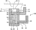
本発明の実施の形態1に係るオイルジェットの構成は図1を用いて説明することができる。図1の縦断面図に示すように、本実施の形態に係るオイルジェット100は内燃機関のシリンダブロック40に取り付けられるボディー2を備えている。ボディー2のシリンダブロック40への取り付けは、例えば、プレート(図示省略)を介して行うことができる。シリンダブロック40には、オイルポンプ(図示省略)によって加圧されたオイルが流れるオイル通路42が形成されている。オイルポンプは内燃機関のクランクシャフトから受ける動力によって駆動されるため、内燃機関の回転数が低いときにはオイル通路42内の油圧は低く、回転数が高くなるにつれてオイル通路42内の油圧も高くなっていく。ボディー2には、このオイル通路42に開口するオイル供給ポート6が形成されている。
The configuration of the oil jet according to Embodiment 1 of the present invention can be described with reference to FIG. As shown in the longitudinal sectional view of FIG. 1, an oil jet 100 according to the present embodiment includes a body 2 attached to a cylinder block 40 of an internal combustion engine. Attachment of the body 2 to the cylinder block 40 can be performed via a plate (not shown), for example. The cylinder block 40 is formed with an oil passage 42 through which oil pressurized by an oil pump (not shown) flows. Since the oil pump is driven by the power received from the crankshaft of the internal combustion engine, the hydraulic pressure in the oil passage 42 is low when the rotational speed of the internal combustion engine is low, and the hydraulic pressure in the oil passage 42 increases as the rotational speed increases. Go. An oil supply port 6 that opens to the oil passage 42 is formed in the body 2.
ボディー2には、オイル供給ポート6を入口とするシリンダ4が形成されている。シリンダ4はボディー2を貫通して形成されるが、その出口はプラグ8によって蓋をされている。すなわち、プラグ8がシリンダ4の底部を構成する。これにより、シリンダ4の中には、一方の端部は開放され他方の端部は閉塞された空間(後述する閉区画24)が形成されている。シリンダ4の側面であってその入口の近くには、シリンダ4よりも小径のオイル噴射ポート10が開口している。ボディー2には、第1オイル噴射ノズル12がロウ付けなどによって取り付けられており、第1オイル噴射ノズル12に形成された第1オイル噴射通路14がオイル噴射ポート10に連通されている。第1オイル噴射通路14の先端部は、第1オイル噴射通路14内を流れるオイルの流速を高めるために、通路出口に向かうにつれ直径が小さくなるように絞られている。第1オイル噴射ノズル12の先端は、内燃機関のピストンの裏面に向けられている。なお、図1には、第1オイル噴射ノズル12は一本のみ示されているが、オイル噴射ポート10をシリンダ4の周方向に複数形成することによって複数本の第1オイル噴射ノズル12をボディー2に取り付けることもできる。
The body 2 is formed with a cylinder 4 having an oil supply port 6 as an inlet. The cylinder 4 is formed through the body 2, and its outlet is covered with a plug 8. That is, the plug 8 constitutes the bottom of the cylinder 4. Thereby, in the cylinder 4, a space (a closed section 24 described later) in which one end is opened and the other end is closed is formed. An oil injection port 10 having a smaller diameter than that of the cylinder 4 is opened near the inlet of the side surface of the cylinder 4. A first oil injection nozzle 12 is attached to the body 2 by brazing or the like, and a first oil injection passage 14 formed in the first oil injection nozzle 12 is communicated with the oil injection port 10. The tip of the first oil injection passage 14 is narrowed so that the diameter decreases toward the passage outlet in order to increase the flow velocity of the oil flowing through the first oil injection passage 14. The tip of the first oil injection nozzle 12 is directed to the back surface of the piston of the internal combustion engine. Although only one first oil injection nozzle 12 is shown in FIG. 1, a plurality of oil injection ports 10 are formed in the circumferential direction of the cylinder 4 to form a plurality of first oil injection nozzles 12. 2 can also be attached.
シリンダ4には、ピストン弁16がシリンダ4の壁面に沿って往復移動自在となるように収容されている。また、シリンダ4には、バネ18が収容されている。バネ18は、コイル状の圧縮バネであってピストン弁16とシリンダ4の底面(プラグ8の基準面8a)との間に配置されている。また、プラグ8には、ストッパ20が一体的に形成されている。ストッパ20は円柱形状を有し、バネ18の内側においてシリンダ4の底部から(プラグ8の基準面8aに対して)シリンダ4内に突き出ている。
The piston valve 16 is accommodated in the cylinder 4 so as to be reciprocally movable along the wall surface of the cylinder 4. The cylinder 4 houses a spring 18. The spring 18 is a coiled compression spring and is disposed between the piston valve 16 and the bottom surface of the cylinder 4 (reference surface 8a of the plug 8). The plug 8 is integrally formed with a stopper 20. The stopper 20 has a cylindrical shape, and projects into the cylinder 4 from the bottom of the cylinder 4 (relative to the reference surface 8 a of the plug 8) inside the spring 18.
ピストン弁16の移動範囲は、このストッパ20によって下方側への移動が制限され、オイル供給ポート6とシリンダ4との間の段付き部22によって上方向への移動が制限されることによって特定される。バネ18の長さは、ピストン弁16に油圧が作用していない状態において、ピストン弁16が段付き部22に突き当たり、かつオイル噴射ポート10を塞ぐ位置にくるように調整されている。ストッパ20の高さは、ピストン弁16が下方に移動することによって後述のリーク孔28を塞がないように設定されている。
The movement range of the piston valve 16 is specified by restricting the downward movement by the stopper 20 and restricting the upward movement by the stepped portion 22 between the oil supply port 6 and the cylinder 4. The The length of the spring 18 is adjusted so that the piston valve 16 comes into contact with the stepped portion 22 and closes the oil injection port 10 when no hydraulic pressure is applied to the piston valve 16. The height of the stopper 20 is set so that the later-described leak hole 28 is not blocked when the piston valve 16 moves downward.
シリンダ4内には、ピストン弁16とシリンダ4の側面及び底部とによって囲まれた閉区画24が形成されている。ピストン弁16には、この閉区画24をオイル供給ポート6の側に連通させるオリフィス26が形成されている。このため、オイルジェット100をシリンダブロック40に取り付けたときには、閉区画24内にはオリフィス26を介してオイルが満たされる。ただし、閉区画24の油圧には、次に述べる構成によりオイル通路42の油圧に対する差圧が発生させられる。以下、この閉区画24を差圧室と称する。
In the cylinder 4, a closed section 24 surrounded by the piston valve 16 and the side surface and bottom of the cylinder 4 is formed. The piston valve 16 is formed with an orifice 26 that allows the closed section 24 to communicate with the oil supply port 6 side. For this reason, when the oil jet 100 is attached to the cylinder block 40, the closed compartment 24 is filled with oil through the orifice 26. However, a differential pressure with respect to the hydraulic pressure of the oil passage 42 is generated in the hydraulic pressure of the closed section 24 by the configuration described below. Hereinafter, the closed section 24 is referred to as a differential pressure chamber.
差圧室24の底部はプラグ8によって形成されている。シリンダ4の側面には、差圧室24内のオイルをシリンダ4の外へ漏出させるためのリーク孔28が開口している。リーク孔28の流路断面積は、差圧室24の断面積に比較すれば格段に小さく形成されている。また、リーク孔28の流路断面積は、オリフィス26の流路断面積よりも小さく形成されている。このようなリーク孔28がボディー2に形成されることで、差圧室24からボディー2の外へオイルが漏れ出し、それにより差圧室24内の油圧が低下する。つまり、オイル通路42の油圧と差圧室24の油圧との間に差圧が発生する。
The bottom of the differential pressure chamber 24 is formed by the plug 8. On the side surface of the cylinder 4, a leak hole 28 for allowing the oil in the differential pressure chamber 24 to leak out of the cylinder 4 is opened. The cross-sectional area of the leak hole 28 is significantly smaller than the cross-sectional area of the differential pressure chamber 24. Further, the channel cross-sectional area of the leak hole 28 is formed smaller than the channel cross-sectional area of the orifice 26. By forming such a leak hole 28 in the body 2, oil leaks out of the body 2 from the differential pressure chamber 24, thereby reducing the hydraulic pressure in the differential pressure chamber 24. That is, a differential pressure is generated between the hydraulic pressure in the oil passage 42 and the hydraulic pressure in the differential pressure chamber 24.
さらに、ボディー2には、第2オイル噴射ノズル30がロウ付けなどによって取り付けられており、第1オイル噴射ノズル30に形成された第1オイル噴射通路32がリーク孔28(第2のオイル噴射ポートとしても機能)に連通されている。第2オイル噴射通路32の先端部は、第2オイル噴射通路32内を流れるオイルの流速を高めるために、通路出口に向かうにつれ直径が小さくなるように絞られている。第2オイル噴射ノズル30の先端は、内燃機関のシリンダボアに向けられている。なお、図1には、第2オイル噴射ノズル30は一本のみ示されているが、リーク孔28をシリンダ4の周方向に複数形成することによって複数本の第2オイル噴射ノズル30をボディー2に取り付けることもできる。
Further, a second oil injection nozzle 30 is attached to the body 2 by brazing or the like, and a first oil injection passage 32 formed in the first oil injection nozzle 30 is connected to a leak hole 28 (second oil injection port). As well as function). The tip of the second oil injection passage 32 is narrowed so that the diameter decreases toward the passage outlet in order to increase the flow velocity of the oil flowing in the second oil injection passage 32. The tip of the second oil injection nozzle 30 is directed to the cylinder bore of the internal combustion engine. Although only one second oil injection nozzle 30 is shown in FIG. 1, a plurality of second oil injection nozzles 30 are formed in the body 2 by forming a plurality of leak holes 28 in the circumferential direction of the cylinder 4. It can also be attached to.
さらに付け加えると、閉塞されたシリンダ4の底部(プラグ8)は、リーク孔28のシリンダ4への開口位置よりもシリンダ4における重力方向下側に位置している。より具体的には、リーク孔28は、差圧室24の上下方向(重力方向)の最低位置(プラグ8の基準面8a)よりも上側において差圧室24と連通している。より詳しくは、リーク孔28は、プラグ8の基準面8aよりは上側であってストッパ20の先端よりは下側となる部位においてシリンダ4の側面に形成されている。なお、シリンダ4の底部(ストッパ20)が重力方向下側に位置するようになっていれば、シリンダ4の中心軸線方向と重力方向とは、完全に一致していることまでは必要ではない。
In addition, the bottom portion (plug 8) of the closed cylinder 4 is located below the opening position of the leak hole 28 in the cylinder 4 in the gravity direction. More specifically, the leak hole 28 communicates with the differential pressure chamber 24 above the lowest position (reference surface 8a of the plug 8) in the vertical direction (gravity direction) of the differential pressure chamber 24. More specifically, the leak hole 28 is formed on the side surface of the cylinder 4 at a portion above the reference surface 8 a of the plug 8 and below the tip of the stopper 20. In addition, if the bottom part (stopper 20) of the cylinder 4 is positioned on the lower side in the gravity direction, it is not necessary that the central axis direction of the cylinder 4 and the gravity direction completely coincide with each other.
次に、本実施の形態に係るオイルジェット100の動作について図2及び図3を用いて説明する。なお、図2及び図3には、オイルジェット100内のオイルの流れを矢印線で示している。
Next, the operation of the oil jet 100 according to the present embodiment will be described with reference to FIGS. 2 and 3, the flow of oil in the oil jet 100 is indicated by an arrow line.
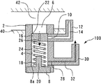
本実施の形態に係るオイルジェット100の構成によれば、ピストン弁16にはオイル通路42を流れるオイルの油圧がオイル供給ポート6側から作用する。そして、それと同時に、差圧室24内の油圧とバネ18による付勢力とが逆方向からピストン弁16に作用する。前者はピストン弁16に対して開弁方向の力として作用し、後者は閉弁方向の力として作用する。よって、差圧室24内の油圧による力とバネ18の付勢力との合力がオイル通路42内の油圧による力以上になっていれば、図2の模式図に示すように、ピストン弁16はオイル噴射ポート10を塞ぐ位置に保持される。つまり、ピストン弁16は閉弁状態に維持される。ただし、オイルジェット100の内部では、差圧室24からリーク孔28を通って漏出するオイルの流れが存在する。このようにリーク孔28へオイルが供給されることで、第2オイル噴射ノズル30からのオイル噴射が達成される。
According to the configuration of the oil jet 100 according to the present embodiment, the oil pressure of the oil flowing through the oil passage 42 acts on the piston valve 16 from the oil supply port 6 side. At the same time, the hydraulic pressure in the differential pressure chamber 24 and the urging force of the spring 18 act on the piston valve 16 from opposite directions. The former acts as a force in the valve opening direction on the piston valve 16, and the latter acts as a force in the valve closing direction. Therefore, if the resultant force of the hydraulic pressure in the differential pressure chamber 24 and the biasing force of the spring 18 is equal to or greater than the force of the hydraulic pressure in the oil passage 42, the piston valve 16 is as shown in the schematic diagram of FIG. The oil injection port 10 is held at a position for closing. That is, the piston valve 16 is maintained in a closed state. However, inside the oil jet 100, there is an oil flow that leaks from the differential pressure chamber 24 through the leak hole 28. By supplying oil to the leak hole 28 in this way, oil injection from the second oil injection nozzle 30 is achieved.
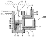
一方、オイル通路42内の油圧による力が差圧室24内の油圧による力とバネ18の付勢力との合力よりも大きくなった場合には、図3の模式図に示すように、ピストン弁16はオイル通路42から供給されるオイルに押されてオイル噴射ポート10を塞ぐ位置から移動する。これによりピストン弁16は開弁状態となってオイル噴射ポート10とオイル供給ポート6とが連通し、オイル噴射ポート10へオイルが供給されて第1オイル噴射ノズル12からのオイル噴射が達成される。この場合においても、オイルジェット100の内部では、ピストン弁16の閉弁時よりは弱い流れではあるが、差圧室24からリーク孔28を通って漏出するオイルの流れが存在する。このため、ピストン弁16の開弁後においても、リーク孔28へオイルが供給されて第2オイル噴射ノズル30からのオイル噴射が達成される。
On the other hand, when the force due to the hydraulic pressure in the oil passage 42 becomes larger than the resultant force of the hydraulic pressure in the differential pressure chamber 24 and the biasing force of the spring 18, as shown in the schematic diagram of FIG. 16 moves from a position where it is pushed by the oil supplied from the oil passage 42 and closes the oil injection port 10. As a result, the piston valve 16 is opened, the oil injection port 10 and the oil supply port 6 communicate with each other, and oil is supplied to the oil injection port 10 to achieve oil injection from the first oil injection nozzle 12. . Even in this case, the flow of oil leaking from the differential pressure chamber 24 through the leak hole 28 exists inside the oil jet 100, although the flow is weaker than when the piston valve 16 is closed. For this reason, even after the piston valve 16 is opened, oil is supplied to the leak hole 28 and the oil injection from the second oil injection nozzle 30 is achieved.
ピストン弁16の位置が一定の場合にはバネ18の付勢力は一定であることから、ピストン弁16を開弁させるのに必要なオイル通路42内の油圧は差圧室24内の油圧によって決まる。差圧室24内の油圧は差圧室24に入るオイルの流量と差圧室24から出るオイルの流量との関係によって変化する。差圧室24にはオリフィス26を通ってオイルが流入するため、その流量Q1は次の式1で表されるようにベルヌーイの定理にしたがう。つまり、オリフィス26を通過するオイルの流量Q1はオイル通路42内の油圧PM/Gと差圧室24内の油圧PINとの差圧の1/2乗に比例し、オイル密度ρの1/2乗に反比例する。なお、式1においてCは流量係数、Aはオリフィス26の流路断面積である。さらに付け加えると、オリフィス26は、上記のベルヌーイの定理にしたがう流路として機能するように、その寸法(流路の径や幅など)が設定されている。

Since the biasing force of the spring 18 is constant when the position of the piston valve 16 is constant, the hydraulic pressure in the oil passage 42 required to open the piston valve 16 is determined by the hydraulic pressure in the differential pressure chamber 24. . The oil pressure in the differential pressure chamber 24 varies depending on the relationship between the flow rate of oil entering the differential pressure chamber 24 and the flow rate of oil exiting the differential pressure chamber 24. Since oil flows into the differential pressure chamber 24 through the orifice 26, the flow rate Q1 is in accordance with Bernoulli's theorem as expressed by the following equation (1). That is, the flow rate Q1 of the oil passing through the orifice 26 is proportional to the square of the differential pressure between the hydraulic pressure P M / G in the oil passage 42 and the hydraulic pressure P IN in the differential pressure chamber 24, and the oil density ρ is 1. / Inversely proportional to the square. In Equation 1, C is a flow coefficient, and A is a cross-sectional area of the orifice 26. In addition, the size (diameter, width, etc.) of the orifice 26 is set so that it functions as a flow passage according to the Bernoulli theorem.
一方、差圧室24からはリーク孔28を通ってオイルが漏出するため、その流量Q2は次の式2で表されるようにハーゲン・ポアズイユの法則にしたがう。つまり、リーク孔28を通過するオイルの流量Q2は差圧室24内の油圧PINと大気圧POUTとの差圧に比例し、オイル粘度ηに反比例する。なお、式2においてBは係数である。さらに付け加えると、リーク孔28およびこれに連通する第2オイル噴射通路32は、上記のハーゲン・ポアズイユの法則にしたがう流路として機能するように、それらの寸法(流路の径や長さなど)が設定されている。
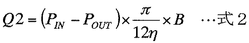
On the other hand, since oil leaks from the differential pressure chamber 24 through the leak hole 28, the flow rate Q2 is in accordance with Hagen-Poiseuille's law as expressed by the following equation 2. That is, the flow rate Q2 of oil passing through the leak hole 28 is proportional to the differential pressure between the hydraulic pressure P IN and the atmospheric pressure P OUT in the differential pressure chamber 24, and inversely proportional to the oil viscosity η. In Equation 2, B is a coefficient. In addition, the leak hole 28 and the second oil injection passage 32 communicating with the leak hole 28 are dimensioned so as to function as a flow path in accordance with the Hagen-Poiseuille law (the diameter and length of the flow path). Is set.
上記の2つの式から分かるように、オリフィス26を通過するオイルの流量にはオイル密度が影響するが、リーク孔28を通過するオイルの流量にはオイル粘度が影響する。オイル密度とオイル粘度はともに油温の影響は受けるものの、その感度は大きく異なる。具体的には、油温の変化に対するオイル密度の変化はほとんどなく、冷間時から暖機の完了までの温度域においてオイル密度はほぼ一定である。一方、油温の変化に対するオイル粘度の変化は極めて大きく、冷間時のオイル粘度は暖機後のオイル粘度よりも20倍ほど高い。
As can be seen from the above two equations, the oil density affects the flow rate of the oil passing through the orifice 26, but the oil viscosity affects the flow rate of the oil passing through the leak hole 28. Oil density and oil viscosity are both affected by oil temperature, but their sensitivity differs greatly. Specifically, there is almost no change in the oil density with respect to the change in the oil temperature, and the oil density is substantially constant in the temperature range from cold to completion of warm-up. On the other hand, the change of the oil viscosity with respect to the change of the oil temperature is extremely large, and the oil viscosity in the cold state is about 20 times higher than the oil viscosity after the warm-up.
このような油温に対するオイル密度とオイル粘度の各特性により、オリフィス26から差圧室24内に流入するオイルの流量は油温によって大きく変化しないものの、リーク孔28から漏出するオイルの流量は油温が高くなるほど増大する。リーク孔28から漏出するオイルの流量が大きいほど差圧室24内の油圧は低下し、ピストン弁16を開弁させるのに必要なオイル通路42内の油圧、すなわち開弁圧は低下する。よって、暖機完了後のように油温が高い場合には、リーク孔28からオイルが漏れやすいために開弁圧は低く、冷間時のように油温が低い場合には、リーク孔28からオイルが漏れにくいために開弁圧は高くなる。
Due to the characteristics of the oil density and the oil viscosity with respect to the oil temperature, the flow rate of oil flowing into the differential pressure chamber 24 from the orifice 26 does not vary greatly depending on the oil temperature, but the flow rate of oil leaking from the leak hole 28 is It increases with increasing temperature. The greater the flow rate of oil leaking from the leak hole 28, the lower the oil pressure in the differential pressure chamber 24, and the oil pressure in the oil passage 42 required to open the piston valve 16, that is, the valve opening pressure, decreases. Therefore, when the oil temperature is high as after the warm-up is completed, the oil is liable to leak from the leak hole 28, so that the valve opening pressure is low. When the oil temperature is low as in the cold time, the leak hole 28 Since the oil is difficult to leak from, the valve opening pressure becomes high.
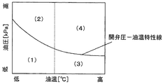
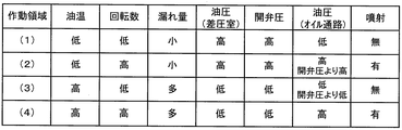
図4では、本実施の形態に係るオイルジェット100の開弁圧-油温特性が縦軸に油圧をとり横軸に油温をとったグラフで表されている。このグラフに示すように、本実施の形態に係るオイルジェット100によれば、開弁圧は油温が高いほど低く油温が低いほど高くなるように機械的に自動調整される。なお、図4のグラフでは、オイルジェット100の作動領域が油温と油圧とによって4つの領域に分けられている。以下、各作動領域におけるオイルジェット100の動作とそれによる効果について図5の表を参照して説明する。
In FIG. 4, the valve opening pressure-oil temperature characteristic of the oil jet 100 according to the present embodiment is represented by a graph in which the vertical axis indicates the hydraulic pressure and the horizontal axis indicates the oil temperature. As shown in this graph, according to the oil jet 100 according to the present embodiment, the valve opening pressure is mechanically automatically adjusted such that the higher the oil temperature, the lower the oil temperature, and the higher the oil temperature. In the graph of FIG. 4, the operating region of the oil jet 100 is divided into four regions depending on the oil temperature and the oil pressure. Hereinafter, the operation of the oil jet 100 in each operation region and the effects thereof will be described with reference to the table of FIG.
作動領域(1)は低油温低油圧領域である。油圧は内燃機関の回転数に応じて変化することから、作動領域(1)は低油温低回転領域とも言える。低油温時はオイル粘度が高いため、オリフィス26を通過して差圧室24に流入したオイルはリーク孔28から漏れにくい。したがって、差圧室24の油圧が高くなってピストン弁16の開弁圧は高くなる。すると、オイル通路42内の油圧が低い低回転域ではピストン弁16が開弁せず、第1オイル噴射ノズル12によるオイル噴射は行われない。内燃機関が作動領域(1)にある場合、内燃機関のピストンの温度は低いためにオイルによる冷却は必要としない。むしろ、第1オイル噴射ノズル12からのオイル噴射の停止によってピストンの過冷却を防止することができる。
The operating area (1) is a low oil temperature and low oil pressure area. Since the hydraulic pressure changes in accordance with the rotational speed of the internal combustion engine, it can be said that the operation region (1) is a low oil temperature low rotation region. Since the oil viscosity is high at a low oil temperature, the oil that has flowed into the differential pressure chamber 24 through the orifice 26 is less likely to leak from the leak hole 28. Therefore, the hydraulic pressure in the differential pressure chamber 24 increases and the valve opening pressure of the piston valve 16 increases. Then, the piston valve 16 does not open in a low rotation range where the oil pressure in the oil passage 42 is low, and oil injection by the first oil injection nozzle 12 is not performed. When the internal combustion engine is in the operating region (1), cooling with oil is not required because the piston temperature of the internal combustion engine is low. Rather, piston overcooling can be prevented by stopping oil injection from the first oil injection nozzle 12.
作動領域(2)は低油温高油圧領域、すなわち、低油温高回転領域である。冷間状態の内燃機関が高回転で運転される状況がこの領域に該当し、ピストンの温度は冷却が必要な程度まで上昇する。本実施の形態に係るオイルジェット100によれば、この作動領域(2)では、オイル通路42内の油圧が開弁圧を上回ったときにピストン弁16が開弁し、第1オイル噴射ノズル12によるオイル噴射が行われる。これにより、高温になったピストンを効果的に冷却することができる。
The operating region (2) is a low oil temperature high hydraulic pressure region, that is, a low oil temperature high rotation region. A situation where a cold internal combustion engine is operated at a high rotation speed corresponds to this region, and the temperature of the piston rises to a level that requires cooling. According to the oil jet 100 according to the present embodiment, in this operation region (2), the piston valve 16 opens when the hydraulic pressure in the oil passage 42 exceeds the valve opening pressure, and the first oil injection nozzle 12 Oil injection is performed. Thereby, the piston which became high temperature can be cooled effectively.
作動領域(3)は高油温低油圧領域、すなわち、高油温低回転領域である。高油温時はオイル粘度が低いため、オリフィス26を通過して差圧室24に流入したオイルはリーク孔28から漏れやすい。したがって、差圧室24の油圧が低くなってピストン弁16の開弁圧は低くなる。しかし、低回転域ではオイル通路42内の油圧も低いためにピストン弁16は開弁せず、第1オイル噴射ノズル12によるオイル噴射は行われない。内燃機関が作動領域(3)にある場合、油温は高いものの、回転数が低いためにピストンの温度はあまり上昇しない。よって、オイルによるピストンの冷却は必要とせず、むしろ、第1オイル噴射ノズル12からのオイル噴射の停止によってピストンの過冷却を防止することができる。
The operating region (3) is a high oil temperature and low oil pressure region, that is, a high oil temperature and low rotation region. Since the oil viscosity is low at a high oil temperature, the oil that has flowed into the differential pressure chamber 24 through the orifice 26 tends to leak from the leak hole 28. Accordingly, the hydraulic pressure in the differential pressure chamber 24 is lowered, and the valve opening pressure of the piston valve 16 is lowered. However, since the hydraulic pressure in the oil passage 42 is low in the low rotation range, the piston valve 16 does not open and oil injection by the first oil injection nozzle 12 is not performed. When the internal combustion engine is in the operating region (3), although the oil temperature is high, the temperature of the piston does not increase so much because the rotational speed is low. Therefore, it is not necessary to cool the piston with oil, but rather, the piston can be prevented from being overcooled by stopping the oil injection from the first oil injection nozzle 12.
作動領域(4)は高油温高油圧領域、すなわち、高油温高回転領域である。この作動領域(4)では、オイル通路42内の油圧は高くなる一方、オイル粘度の低下によりリーク孔28からオイルが漏れやすくなってピストン弁16の開弁圧は低くなる。このため、ピストン弁16は容易に開弁して第1オイル噴射ノズル12によるオイル噴射が行われ、高温になったピストンは効果的に冷却される。
The operating region (4) is a high oil temperature high hydraulic pressure region, that is, a high oil temperature high rotation region. In this operation region (4), the oil pressure in the oil passage 42 is increased, but the oil is liable to leak from the leak hole 28 due to the decrease in the oil viscosity, and the valve opening pressure of the piston valve 16 is decreased. For this reason, the piston valve 16 is easily opened, the oil injection by the first oil injection nozzle 12 is performed, and the piston that has reached a high temperature is effectively cooled.
以上のように、本実施の形態に係るオイルジェット100によれば、内燃機関のピストンの冷却が必要な作動領域では第1オイル噴射ノズル12からのオイル噴射を確実に実行し、ピストンの冷却が不要な作動領域では当該オイル噴射を確実に停止することができる。さらに、本実施の形態に係るオイルジェット100によれば、万が一故障が生じたときでも、具体的にはピストン弁16を動作させるバネ18が壊れた場合であっても、必要なオイル噴射は確実に行うことができる。すなわち、バネ18は開弁を防ぐ方向にピストン弁16を付勢しているので、バネ18が壊れた場合にはその付勢力がなくなり、ピストン弁16はより低い油圧によって開弁するようになる。これによればピストンに対するオイルの噴射は確実に行われるので、オイルジェット100の故障によってピストンの焼つきなどの不具合が発生することは防止される。
As described above, according to the oil jet 100 according to the present embodiment, the oil injection from the first oil injection nozzle 12 is reliably performed in the operation region where the piston of the internal combustion engine needs to be cooled, and the piston is cooled. The oil injection can be surely stopped in the unnecessary operation region. Furthermore, according to the oil jet 100 according to the present embodiment, even if a failure occurs, specifically, even when the spring 18 that operates the piston valve 16 is broken, the necessary oil injection is ensured. Can be done. That is, since the spring 18 urges the piston valve 16 in a direction to prevent the valve from opening, when the spring 18 is broken, the urging force is lost, and the piston valve 16 is opened by a lower hydraulic pressure. . According to this, since the oil is reliably injected to the piston, it is possible to prevent a malfunction such as seizure of the piston due to the failure of the oil jet 100.
また、本実施の形態に係るオイルジェット100によれば、作動領域(1)~(4)の何れにおいても、ピストン弁16の開閉およびオイルの粘度の高低の影響による噴射の勢いの差はあるものの、第2オイル噴射ノズル30からシリンダボアに向けてオイル噴射が行われる。これにより、開弁圧を油温に応じて機械的に自動調整できるようにするために備えたリーク孔28から外部に漏出するオイルを、単に漏らすのではなく、シリンダボアの潤滑のために有効利用できるようになる。このように、本実施形態のオイルジェット100は、内燃機関のピストンの冷却が必要な作動領域においてピストンの裏面にオイルを噴射する第1オイル噴射ノズル12と、シリンダボアに対して常時オイルを噴射する第2オイル噴射ノズル30とを備えているといえる。
Further, according to the oil jet 100 according to the present embodiment, there is a difference in the momentum of the injection due to the opening / closing of the piston valve 16 and the effect of the oil viscosity in any of the operation regions (1) to (4). However, oil injection is performed from the second oil injection nozzle 30 toward the cylinder bore. Thereby, the oil leaking to the outside from the leak hole 28 provided for enabling the valve opening pressure to be automatically adjusted automatically according to the oil temperature is effectively used for lubricating the cylinder bore rather than merely leaking. become able to. As described above, the oil jet 100 according to the present embodiment constantly injects oil into the cylinder bore and the first oil injection nozzle 12 that injects oil to the back surface of the piston in the operation region where the piston of the internal combustion engine needs to be cooled. It can be said that the second oil injection nozzle 30 is provided.
また、既述したように、本オイルジェット100では、リーク孔28およびこれに接続される第2オイル噴射ノズル30は、シリンダ4の側面に設置されている。これにより、差圧室24内に異物が流入した場合であっても、異物は自重によってシリンダ4の底部に向かうため、リーク孔28が異物によって詰まりにくくすることができる。これにより、シリンダボア用の第2オイル噴射ノズル30からのオイル噴射を安定して行えるようになる。また、リーク孔28が異物によって詰まることによって、開弁圧の機械的な自動調整に不具合が生ずることも防止される。このように、本実施形態の構成によれば、オイルジェット100の内部にフィルタなどの異物除去部材を設置する必要なしに簡易な構造で耐異物性を向上できるようになる。
As described above, in the present oil jet 100, the leak hole 28 and the second oil injection nozzle 30 connected to the leak hole 28 are installed on the side surface of the cylinder 4. As a result, even when foreign matter flows into the differential pressure chamber 24, the foreign matter is directed toward the bottom of the cylinder 4 due to its own weight, so that the leak hole 28 can be less likely to be clogged with foreign matter. Thereby, the oil injection from the second oil injection nozzle 30 for the cylinder bore can be stably performed. In addition, it is possible to prevent troubles from occurring in the mechanical automatic adjustment of the valve opening pressure due to the clogging of the leak holes 28 with foreign substances. Thus, according to the configuration of the present embodiment, the foreign matter resistance can be improved with a simple structure without the need to install a foreign matter removing member such as a filter inside the oil jet 100.
ところで、上述した実施の形態1においては、第2オイル噴射ノズル30をシリンダボアに向けてオイルを噴射するものとして備えることとしている。しかしながら、シリンダボア以外にもオイルが不足しがちとなる等の理由によってオイルの供給を常時受けたい他の部位があれば、本発明における第2噴射ノズルの先端は、そのような他の部位に対して向けられたものであってもよい。
By the way, in the first embodiment described above, the second oil injection nozzle 30 is provided as one that injects oil toward the cylinder bore. However, if there is another part other than the cylinder bore where oil is apt to be supplied due to a tendency to run out of oil, the tip of the second injection nozzle in the present invention is not It may be directed.
2 ボディー
4 シリンダ
6 オイル供給ポート
8 プラグ
8a プラグの基準面
10 オイル噴射ポート
12 第1オイル噴射ノズル
14 第1オイル噴射通路
16 ピストン弁
18 バネ
20 ストッパ
22 段付き部
24 差圧室(閉区画)
26 オリフィス
28 リーク孔
30 第2オイル噴射ノズル
32 第2オイル噴射通路
40 シリンダブロック
42 オイル通路
100 オイルジェット 2Body 4 Cylinder 6 Oil supply port 8 Plug 8a Plug reference surface 10 Oil injection port 12 First oil injection nozzle 14 First oil injection passage 16 Piston valve 18 Spring 20 Stopper 22 Stepped portion 24 Differential pressure chamber (closed compartment)
26Orifice 28 Leak hole 30 Second oil injection nozzle 32 Second oil injection passage 40 Cylinder block 42 Oil passage 100 Oil jet
4 シリンダ
6 オイル供給ポート
8 プラグ
8a プラグの基準面
10 オイル噴射ポート
12 第1オイル噴射ノズル
14 第1オイル噴射通路
16 ピストン弁
18 バネ
20 ストッパ
22 段付き部
24 差圧室(閉区画)
26 オリフィス
28 リーク孔
30 第2オイル噴射ノズル
32 第2オイル噴射通路
40 シリンダブロック
42 オイル通路
100 オイルジェット 2
26
Claims (3)
- 内燃機関のシリンダブロック内のオイル通路に開口するオイル供給ポートと、一方の端部が前記オイル供給ポートに連通し他方の端部は閉塞されたシリンダと、前記シリンダの側面に開口するオイル噴射ポートとを有するボディーと、
前記シリンダに収容されて前記シリンダ内に閉区画を形成し、且つ、前記閉区画を前記オイル供給ポートの側に連通させるオリフィスを備えるピストン弁と、
前記オイル噴射ポートを塞ぐ位置に前記ピストン弁を付勢するバネと、
前記オイル噴射ポートに接続され、オイルの噴射の向きを調整する第1オイル噴射ノズルと、
を備え、
前記シリンダの側面には、前記閉区画から前記シリンダの外へオイルを漏出させるリーク孔が開口しており、
前記リーク孔に接続され、オイルの噴射の向きを調整する第2オイル噴射ノズルをさらに備えることを特徴とするオイルジェット。 An oil supply port that opens to an oil passage in a cylinder block of an internal combustion engine, a cylinder that has one end communicating with the oil supply port and the other end that is closed, and an oil injection port that opens to the side of the cylinder A body having
A piston valve that is housed in the cylinder to form a closed section in the cylinder, and that includes an orifice that communicates the closed section with the oil supply port;
A spring for biasing the piston valve at a position closing the oil injection port;
A first oil injection nozzle connected to the oil injection port for adjusting the direction of oil injection;
With
On the side surface of the cylinder, there is a leak hole that leaks oil out of the cylinder from the closed compartment,
An oil jet, further comprising a second oil injection nozzle that is connected to the leak hole and adjusts the direction of oil injection. - 閉塞された前記シリンダの前記他方の端部は、前記リーク孔の前記シリンダへの開口位置よりも前記シリンダにおける重力方向下側に位置していることを特徴とする請求項1に記載のオイルジェット。 2. The oil jet according to claim 1, wherein the other end of the closed cylinder is positioned below the position of the leak hole in the cylinder in the direction of gravity in the cylinder. .
- 前記第1オイル噴射ノズルの先端は、前記内燃機関の筒内を往復移動するピストンの裏面に向けられており、
前記第2オイル噴射ノズルの先端は、前記内燃機関のシリンダボアに向けられていることを特徴とする請求項1または2に記載のオイルジェット。 The tip of the first oil injection nozzle is directed to the back surface of the piston that reciprocates in the cylinder of the internal combustion engine,
The oil jet according to claim 1 or 2, wherein a tip of the second oil injection nozzle is directed to a cylinder bore of the internal combustion engine.
Priority Applications (3)
| Application Number | Priority Date | Filing Date | Title |
|---|---|---|---|
| EP14835261.0A EP3032055B1 (en) | 2013-08-09 | 2014-06-09 | Oil jet |
| CN201480044704.7A CN105452619B (en) | 2013-08-09 | 2014-06-09 | Fueling injection equipment |
| US14/910,857 US10233816B2 (en) | 2013-08-09 | 2014-06-09 | Oil jet |
Applications Claiming Priority (2)
| Application Number | Priority Date | Filing Date | Title |
|---|---|---|---|
| JP2013166806A JP6148111B2 (en) | 2013-08-09 | 2013-08-09 | Oil jet |
| JP2013-166806 | 2013-08-09 |
Publications (1)
| Publication Number | Publication Date |
|---|---|
| WO2015019697A1 true WO2015019697A1 (en) | 2015-02-12 |
Family
ID=52461041
Family Applications (1)
| Application Number | Title | Priority Date | Filing Date |
|---|---|---|---|
| PCT/JP2014/065216 WO2015019697A1 (en) | 2013-08-09 | 2014-06-09 | Oil jet |
Country Status (5)
| Country | Link |
|---|---|
| US (1) | US10233816B2 (en) |
| EP (1) | EP3032055B1 (en) |
| JP (1) | JP6148111B2 (en) |
| CN (1) | CN105452619B (en) |
| WO (1) | WO2015019697A1 (en) |
Cited By (1)
| Publication number | Priority date | Publication date | Assignee | Title |
|---|---|---|---|---|
| US10590830B1 (en) * | 2018-10-23 | 2020-03-17 | GM Global Technology Operations LLC | Internal combustion engine including piston cooling jets |
Families Citing this family (15)
| Publication number | Priority date | Publication date | Assignee | Title |
|---|---|---|---|---|
| DE102014005364A1 (en) * | 2014-04-11 | 2015-10-29 | Mahle International Gmbh | Assembly of a piston and an oil spray nozzle for an internal combustion engine |
| CN105545443A (en) * | 2015-12-31 | 2016-05-04 | 潍柴动力扬州柴油机有限责任公司 | Piston cooling nozzle |
| CN106091010B (en) * | 2016-06-21 | 2019-03-08 | 中国航空工业集团公司沈阳发动机设计研究所 | A kind of engine chamber duplex burner valve |
| CN106285895A (en) * | 2016-08-29 | 2017-01-04 | 潍柴动力股份有限公司 | A kind of electromotor and piston cooling nozzle assembly |
| DE102016219857A1 (en) * | 2016-10-12 | 2018-04-12 | Bayerische Motoren Werke Aktiengesellschaft | Device for cooling a piston of a reciprocating internal combustion engine |
| DE102016221353A1 (en) * | 2016-10-28 | 2018-05-03 | Mahle International Gmbh | Internal combustion engine |
| AT519000B1 (en) * | 2016-10-31 | 2018-03-15 | Avl List Gmbh | Internal combustion engine |
| DE102017201905B4 (en) | 2017-02-07 | 2022-05-05 | Wagner Gmbh & Co. Kg | Control valve for nozzles and nozzle head with the control valve |
| DE102017212547A1 (en) * | 2017-07-21 | 2019-01-24 | Bayerische Motoren Werke Aktiengesellschaft | Reciprocating internal combustion engine |
| DE102017123664A1 (en) * | 2017-10-11 | 2019-04-11 | Man Truck & Bus Ag | Valve for adjusting a cooling fluid flow for piston cooling |
| US11248515B2 (en) * | 2019-08-02 | 2022-02-15 | Transportation Ip Holdings, Llc | Piston cooling jet system |
| DE102020208867A1 (en) * | 2020-07-16 | 2022-01-20 | Volkswagen Aktiengesellschaft | Diagnostic method for a piston cooling nozzle valve, diagnostic device, control unit, motor vehicle |
| CN112031910A (en) * | 2020-09-30 | 2020-12-04 | 广西玉柴机器股份有限公司 | Arrangement method and structure of spraying hooks opened in grading manner |
| KR20220159159A (en) * | 2021-05-25 | 2022-12-02 | 현대자동차주식회사 | Piston cooling device and control method thereof |
| KR20230021912A (en) * | 2021-08-06 | 2023-02-14 | 현대자동차주식회사 | Pcj solenoid valve diagnostic method |
Citations (5)
| Publication number | Priority date | Publication date | Assignee | Title |
|---|---|---|---|---|
| JPH0642346A (en) | 1992-07-22 | 1994-02-15 | Nissan Motor Co Ltd | Piston cooling device for internal combustion engine |
| JP2006138307A (en) * | 2004-10-15 | 2006-06-01 | Toyota Motor Corp | Internal combustion engine lubricating device |
| JP2011012650A (en) | 2009-07-06 | 2011-01-20 | Matsumoto Jukogyo Kk | Oil jet |
| JP2011064155A (en) | 2009-09-18 | 2011-03-31 | Hitachi Automotive Systems Ltd | Cooling device of piston for internal combustion engine |
| US20130019834A1 (en) * | 2011-07-20 | 2013-01-24 | GM Global Technology Operations LLC | Oil squirter |
Family Cites Families (35)
| Publication number | Priority date | Publication date | Assignee | Title |
|---|---|---|---|---|
| DE2546273C2 (en) * | 1975-10-16 | 1984-11-22 | Audi Nsu Auto Union Ag, 7107 Neckarsulm | Device for regulating piston oil cooling for a piston internal combustion engine |
| US4206726A (en) * | 1977-07-18 | 1980-06-10 | Caterpillar Tractor Co. | Double orifice piston cooling nozzle for reciprocating engines |
| US4276960A (en) * | 1979-05-17 | 1981-07-07 | Ingersoll-Rand Company | Oil distributing means |
| US4508065A (en) * | 1983-03-21 | 1985-04-02 | General Motors Corporation | Piston cooling oil delivery tube assembly |
| JPS61138816A (en) * | 1984-12-07 | 1986-06-26 | Toyota Motor Corp | Fuel evaporation rate control system for direct-injection inernal-combustion engine |
| JPH04121457A (en) * | 1990-09-11 | 1992-04-22 | Zexel Corp | Engine starter device for vehicle with automatic transmission |
| JP3447782B2 (en) * | 1993-01-19 | 2003-09-16 | トヨタ自動車株式会社 | Internal combustion engine lubrication system |
| JP3106058B2 (en) * | 1994-05-20 | 2000-11-06 | 株式会社ユニシアジェックス | Lubrication and cooling equipment for internal combustion engines |
| JP3161282B2 (en) | 1995-05-31 | 2001-04-25 | 日産自動車株式会社 | Internal combustion engine piston cooling system |
| DE19633167A1 (en) * | 1996-08-17 | 1998-02-19 | Porsche Ag | Spray nozzle for the piston cooling of an internal combustion engine |
| US5819692A (en) * | 1997-05-01 | 1998-10-13 | Schafer; Timothy Vernon | Piston cooling oil control valve |
| DE19943516B4 (en) * | 1999-09-11 | 2017-01-19 | Schaeffler Technologies AG & Co. KG | nozzle valve |
| US6488479B1 (en) * | 2001-05-17 | 2002-12-03 | Ford Global Technologies, Inc. | Variable pressure oil pump |
| FR2827009B1 (en) * | 2001-07-04 | 2003-12-12 | Bontaz Centre Sa | PISTON COOLING JET |
| FR2844003B1 (en) * | 2002-09-02 | 2006-06-16 | Bontaz Centre Sa | MULTI-PROJECTION SPRINKLER FOR ENGINE COOLING, AND ENGINES EQUIPPED WITH SUCH SPRAYERS |
| GB2403852B (en) * | 2003-07-07 | 2006-05-31 | Electrolux Outdoor Prod Ltd | Starter |
| US7152623B2 (en) * | 2003-09-09 | 2006-12-26 | Metaldyne Company, Llc | Fluid jet for providing fluid under pressure to a desired location |
| FR2859756B1 (en) * | 2003-09-16 | 2007-09-21 | Bontaz Centre Sa | COOLING DEVICE FOR MOTOR PISTONS. |
| DE102005043232A1 (en) * | 2005-09-09 | 2007-03-15 | Bayerische Motoren Werke Ag | Device for starting the engine of a motor vehicle |
| JP2007113460A (en) * | 2005-10-19 | 2007-05-10 | Nissan Motor Co Ltd | Engine start control device and engine start control method |
| JP4333690B2 (en) * | 2006-05-12 | 2009-09-16 | 株式会社デンソー | Engine start control system |
| DE102009006963A1 (en) * | 2009-01-31 | 2010-08-05 | Dr. Ing. H.C. F. Porsche Aktiengesellschaft | Oil supply |
| JP2011012619A (en) * | 2009-07-03 | 2011-01-20 | Matsumoto Jukogyo Kk | Oil jet |
| US8171907B2 (en) * | 2009-11-19 | 2012-05-08 | Briggs And Stratton Corporation | Push button starting system for outdoor power equipment |
| JP5827164B2 (en) * | 2012-04-04 | 2015-12-02 | トヨタ自動車株式会社 | Oil jet |
| JP5680601B2 (en) | 2012-09-29 | 2015-03-04 | 大豊工業株式会社 | Piston cooling jet |
| JP6011518B2 (en) * | 2013-11-21 | 2016-10-19 | トヨタ自動車株式会社 | Vehicle control apparatus and control method |
| JP6171917B2 (en) * | 2013-12-18 | 2017-08-02 | 株式会社デンソー | Engine starter |
| US9404466B2 (en) * | 2014-06-14 | 2016-08-02 | GM Global Technology Operations LLC | Method for evaluating an engine starting system |
| US9401053B2 (en) * | 2014-09-09 | 2016-07-26 | GM Global Technology Operations LLC | Fault notifications for vehicles |
| US9790910B2 (en) * | 2015-01-13 | 2017-10-17 | Toyota Motor Engineering & Manufacturing North America, Inc. | System and method for preventing unwanted engine restarts while parking a vehicle |
| JP2016194270A (en) * | 2015-03-31 | 2016-11-17 | トヨタ自動車株式会社 | Engine automatic control device |
| JP2016200051A (en) * | 2015-04-09 | 2016-12-01 | トヨタ自動車株式会社 | Engine start control device |
| US9758171B2 (en) * | 2015-06-15 | 2017-09-12 | GM Global Technology Operations LLC | Method and apparatus for controlling a multi-mode powertrain system including an engine having stop/start capability |
| US9951704B2 (en) * | 2015-09-08 | 2018-04-24 | GM Global Technology Operations LLC | No start event monitoring |
-
2013
- 2013-08-09 JP JP2013166806A patent/JP6148111B2/en not_active Expired - Fee Related
-
2014
- 2014-06-09 WO PCT/JP2014/065216 patent/WO2015019697A1/en active Application Filing
- 2014-06-09 CN CN201480044704.7A patent/CN105452619B/en active Active
- 2014-06-09 US US14/910,857 patent/US10233816B2/en active Active
- 2014-06-09 EP EP14835261.0A patent/EP3032055B1/en active Active
Patent Citations (5)
| Publication number | Priority date | Publication date | Assignee | Title |
|---|---|---|---|---|
| JPH0642346A (en) | 1992-07-22 | 1994-02-15 | Nissan Motor Co Ltd | Piston cooling device for internal combustion engine |
| JP2006138307A (en) * | 2004-10-15 | 2006-06-01 | Toyota Motor Corp | Internal combustion engine lubricating device |
| JP2011012650A (en) | 2009-07-06 | 2011-01-20 | Matsumoto Jukogyo Kk | Oil jet |
| JP2011064155A (en) | 2009-09-18 | 2011-03-31 | Hitachi Automotive Systems Ltd | Cooling device of piston for internal combustion engine |
| US20130019834A1 (en) * | 2011-07-20 | 2013-01-24 | GM Global Technology Operations LLC | Oil squirter |
Cited By (1)
| Publication number | Priority date | Publication date | Assignee | Title |
|---|---|---|---|---|
| US10590830B1 (en) * | 2018-10-23 | 2020-03-17 | GM Global Technology Operations LLC | Internal combustion engine including piston cooling jets |
Also Published As
| Publication number | Publication date |
|---|---|
| US10233816B2 (en) | 2019-03-19 |
| EP3032055A1 (en) | 2016-06-15 |
| CN105452619A (en) | 2016-03-30 |
| EP3032055B1 (en) | 2018-01-10 |
| JP2015034537A (en) | 2015-02-19 |
| US20160186642A1 (en) | 2016-06-30 |
| EP3032055A4 (en) | 2017-02-01 |
| CN105452619B (en) | 2018-03-06 |
| JP6148111B2 (en) | 2017-06-14 |
Similar Documents
| Publication | Publication Date | Title |
|---|---|---|
| JP6148111B2 (en) | Oil jet | |
| JP5827164B2 (en) | Oil jet | |
| JP2015034537A5 (en) | ||
| JP2006312936A (en) | Controlled leakage valve for piston cooling nozzle | |
| US9382821B2 (en) | Biased normally open check valve assembly | |
| JP2014070611A (en) | Piston cooling jet | |
| JP2007505281A (en) | Fluid jet for supplying pressurized fluid to a target location | |
| JP4381341B2 (en) | Piston cooling system | |
| FI117643B (en) | Arrangements at fuel injection plant | |
| JP2013217202A (en) | Oil jet | |
| JP3832401B2 (en) | Fuel injection device | |
| JP5526194B2 (en) | Fuel valve for turbocharged large two-cycle diesel engine | |
| US10774726B2 (en) | Valve for adjusting a cooling fluid flow for piston cooling | |
| US20130233271A1 (en) | Oil squirter with damping vent | |
| JP2013249742A (en) | Oil jet | |
| JP2014009603A (en) | Oil jet | |
| JP2006283603A (en) | Piston cooling device for internal combustion engine | |
| RU2679957C1 (en) | Nozzle, equipped with nozzle engine and vehicle | |
| CS234514B1 (en) | Equipment for piston spraying by oil | |
| CN114174650B (en) | Passive piston cooling nozzle control to achieve low speed thermal operation protection | |
| RU2777178C2 (en) | Valve for adjustment of cooling medium flow for cooling pistons | |
| JP2019148231A (en) | Oil jet device | |
| US20190048992A1 (en) | System for controlling a vehicle transmission sump fluid level | |
| JP2014070610A (en) | Piston cooling jet | |
| JP2015004303A (en) | Oil volume adjustment device |
Legal Events
| Date | Code | Title | Description |
|---|---|---|---|
| WWE | Wipo information: entry into national phase |
Ref document number: 201480044704.7 Country of ref document: CN |
|
| 121 | Ep: the epo has been informed by wipo that ep was designated in this application |
Ref document number: 14835261 Country of ref document: EP Kind code of ref document: A1 |
|
| WWE | Wipo information: entry into national phase |
Ref document number: 14910857 Country of ref document: US |
|
| NENP | Non-entry into the national phase |
Ref country code: DE |
|
| WWE | Wipo information: entry into national phase |
Ref document number: 2014835261 Country of ref document: EP |