WO2015008585A1 - 電池の製造方法 - Google Patents
電池の製造方法 Download PDFInfo
- Publication number
- WO2015008585A1 WO2015008585A1 PCT/JP2014/066599 JP2014066599W WO2015008585A1 WO 2015008585 A1 WO2015008585 A1 WO 2015008585A1 JP 2014066599 W JP2014066599 W JP 2014066599W WO 2015008585 A1 WO2015008585 A1 WO 2015008585A1
- Authority
- WO
- WIPO (PCT)
- Prior art keywords
- battery
- charging
- electrolytic solution
- electrode plate
- impregnation state
- Prior art date
- Legal status (The legal status is an assumption and is not a legal conclusion. Google has not performed a legal analysis and makes no representation as to the accuracy of the status listed.)
- Ceased
Links
Images


Classifications
-
- H—ELECTRICITY
- H01—ELECTRIC ELEMENTS
- H01M—PROCESSES OR MEANS, e.g. BATTERIES, FOR THE DIRECT CONVERSION OF CHEMICAL ENERGY INTO ELECTRICAL ENERGY
- H01M10/00—Secondary cells; Manufacture thereof
- H01M10/42—Methods or arrangements for servicing or maintenance of secondary cells or secondary half-cells
- H01M10/44—Methods for charging or discharging
-
- H—ELECTRICITY
- H01—ELECTRIC ELEMENTS
- H01M—PROCESSES OR MEANS, e.g. BATTERIES, FOR THE DIRECT CONVERSION OF CHEMICAL ENERGY INTO ELECTRICAL ENERGY
- H01M10/00—Secondary cells; Manufacture thereof
- H01M10/04—Construction or manufacture in general
- H01M10/049—Processes for forming or storing electrodes in the battery container
-
- G—PHYSICS
- G01—MEASURING; TESTING
- G01R—MEASURING ELECTRIC VARIABLES; MEASURING MAGNETIC VARIABLES
- G01R31/00—Arrangements for testing electric properties; Arrangements for locating electric faults; Arrangements for electrical testing characterised by what is being tested not provided for elsewhere
- G01R31/36—Arrangements for testing, measuring or monitoring the electrical condition of accumulators or electric batteries, e.g. capacity or state of charge [SoC]
- G01R31/385—Arrangements for measuring battery or accumulator variables
-
- H—ELECTRICITY
- H01—ELECTRIC ELEMENTS
- H01M—PROCESSES OR MEANS, e.g. BATTERIES, FOR THE DIRECT CONVERSION OF CHEMICAL ENERGY INTO ELECTRICAL ENERGY
- H01M10/00—Secondary cells; Manufacture thereof
- H01M10/42—Methods or arrangements for servicing or maintenance of secondary cells or secondary half-cells
- H01M10/44—Methods for charging or discharging
- H01M10/446—Initial charging measures
-
- H—ELECTRICITY
- H01—ELECTRIC ELEMENTS
- H01M—PROCESSES OR MEANS, e.g. BATTERIES, FOR THE DIRECT CONVERSION OF CHEMICAL ENERGY INTO ELECTRICAL ENERGY
- H01M10/00—Secondary cells; Manufacture thereof
- H01M10/42—Methods or arrangements for servicing or maintenance of secondary cells or secondary half-cells
- H01M10/48—Accumulators combined with arrangements for measuring, testing or indicating the condition of cells, e.g. the level or density of the electrolyte
-
- H—ELECTRICITY
- H01—ELECTRIC ELEMENTS
- H01M—PROCESSES OR MEANS, e.g. BATTERIES, FOR THE DIRECT CONVERSION OF CHEMICAL ENERGY INTO ELECTRICAL ENERGY
- H01M10/00—Secondary cells; Manufacture thereof
- H01M10/42—Methods or arrangements for servicing or maintenance of secondary cells or secondary half-cells
- H01M10/52—Removing gases inside the secondary cell, e.g. by absorption
-
- H—ELECTRICITY
- H01—ELECTRIC ELEMENTS
- H01M—PROCESSES OR MEANS, e.g. BATTERIES, FOR THE DIRECT CONVERSION OF CHEMICAL ENERGY INTO ELECTRICAL ENERGY
- H01M10/00—Secondary cells; Manufacture thereof
- H01M10/04—Construction or manufacture in general
- H01M10/0404—Machines for assembling batteries
-
- H—ELECTRICITY
- H01—ELECTRIC ELEMENTS
- H01M—PROCESSES OR MEANS, e.g. BATTERIES, FOR THE DIRECT CONVERSION OF CHEMICAL ENERGY INTO ELECTRICAL ENERGY
- H01M10/00—Secondary cells; Manufacture thereof
- H01M10/05—Accumulators with non-aqueous electrolyte
- H01M10/052—Li-accumulators
- H01M10/0525—Rocking-chair batteries, i.e. batteries with lithium insertion or intercalation in both electrodes; Lithium-ion batteries
-
- H—ELECTRICITY
- H01—ELECTRIC ELEMENTS
- H01M—PROCESSES OR MEANS, e.g. BATTERIES, FOR THE DIRECT CONVERSION OF CHEMICAL ENERGY INTO ELECTRICAL ENERGY
- H01M10/00—Secondary cells; Manufacture thereof
- H01M10/05—Accumulators with non-aqueous electrolyte
- H01M10/056—Accumulators with non-aqueous electrolyte characterised by the materials used as electrolytes, e.g. mixed inorganic/organic electrolytes
- H01M10/0564—Accumulators with non-aqueous electrolyte characterised by the materials used as electrolytes, e.g. mixed inorganic/organic electrolytes the electrolyte being constituted of organic materials only
- H01M10/0566—Liquid materials
-
- H—ELECTRICITY
- H01—ELECTRIC ELEMENTS
- H01M—PROCESSES OR MEANS, e.g. BATTERIES, FOR THE DIRECT CONVERSION OF CHEMICAL ENERGY INTO ELECTRICAL ENERGY
- H01M10/00—Secondary cells; Manufacture thereof
- H01M10/05—Accumulators with non-aqueous electrolyte
- H01M10/058—Construction or manufacture
- H01M10/0585—Construction or manufacture of accumulators having only flat construction elements, i.e. flat positive electrodes, flat negative electrodes and flat separators
-
- H—ELECTRICITY
- H01—ELECTRIC ELEMENTS
- H01M—PROCESSES OR MEANS, e.g. BATTERIES, FOR THE DIRECT CONVERSION OF CHEMICAL ENERGY INTO ELECTRICAL ENERGY
- H01M10/00—Secondary cells; Manufacture thereof
- H01M10/42—Methods or arrangements for servicing or maintenance of secondary cells or secondary half-cells
- H01M10/4285—Testing apparatus
-
- Y—GENERAL TAGGING OF NEW TECHNOLOGICAL DEVELOPMENTS; GENERAL TAGGING OF CROSS-SECTIONAL TECHNOLOGIES SPANNING OVER SEVERAL SECTIONS OF THE IPC; TECHNICAL SUBJECTS COVERED BY FORMER USPC CROSS-REFERENCE ART COLLECTIONS [XRACs] AND DIGESTS
- Y02—TECHNOLOGIES OR APPLICATIONS FOR MITIGATION OR ADAPTATION AGAINST CLIMATE CHANGE
- Y02E—REDUCTION OF GREENHOUSE GAS [GHG] EMISSIONS, RELATED TO ENERGY GENERATION, TRANSMISSION OR DISTRIBUTION
- Y02E60/00—Enabling technologies; Technologies with a potential or indirect contribution to GHG emissions mitigation
- Y02E60/10—Energy storage using batteries
-
- Y—GENERAL TAGGING OF NEW TECHNOLOGICAL DEVELOPMENTS; GENERAL TAGGING OF CROSS-SECTIONAL TECHNOLOGIES SPANNING OVER SEVERAL SECTIONS OF THE IPC; TECHNICAL SUBJECTS COVERED BY FORMER USPC CROSS-REFERENCE ART COLLECTIONS [XRACs] AND DIGESTS
- Y02—TECHNOLOGIES OR APPLICATIONS FOR MITIGATION OR ADAPTATION AGAINST CLIMATE CHANGE
- Y02P—CLIMATE CHANGE MITIGATION TECHNOLOGIES IN THE PRODUCTION OR PROCESSING OF GOODS
- Y02P70/00—Climate change mitigation technologies in the production process for final industrial or consumer products
- Y02P70/50—Manufacturing or production processes characterised by the final manufactured product
Definitions
- the present invention relates to a method of manufacturing a battery.
- the impregnation state of the electrolytic solution is measured after pouring (before charging) the electrolytic solution. It is known to do (for example, patent document 1). Specifically, the battery is irradiated with ultrasonic waves after the injection of the electrolytic solution (before charging), and the impregnation completion (impregnation state) of the electrolytic solution is determined based on the transmittance of the ultrasonic waves transmitted through the battery. .
- the impregnation state inspection described in Patent Document 1 is one before charging. However, there are also gases that are newly generated by charging. Some of the gas bubbles may remain between the electrodes. Such batteries with poor impregnation state continue to flow through the manufacturing line until they are detected as deterioration of the battery characteristics (such as under capacity) in the final stage battery characteristic inspection step, which causes a decrease in production efficiency and an increase in production cost. It becomes one of the
- An object of the present invention is to provide a technology that contributes to improvement of production efficiency and reduction of production cost in battery production technology.
- One aspect of the method of manufacturing a battery according to the present invention is a method of manufacturing a battery including a battery element in which a positive electrode plate and a negative electrode plate are stacked via a separator, and an outer package containing the battery element together with an electrolyte.
- the battery element and the electrolytic solution are accommodated in the outer package to constitute a battery, and after charging the battery, the impregnation state of the electrolytic solution between the positive electrode plate and the negative electrode plate is inspected.
- defective products are detected and eliminated in advance, and manufacturing costs are reduced, by detecting at least defects in the electrolytic solution impregnation state due to air bubbles generated by charging the battery before the subsequent steps. be able to.
- FIG. 2 is a cross-sectional view taken along line AA of FIG.
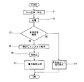
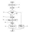
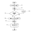
- It is a flowchart which shows the flow of the manufacturing method of the battery which concerns on 1st Embodiment of this invention. It is a flowchart which shows the flow of the manufacturing method of the battery which concerns on 2nd Embodiment of this invention. It is a flowchart which shows the flow of the manufacturing method of the battery which concerns on 3rd Embodiment of this invention. It is a flowchart which shows the flow of the manufacturing method of the battery which is another example of 2nd Embodiment of this invention.
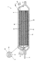
- FIG. 1 is a perspective view of the battery 1
- FIG. 2 is a cross-sectional view taken along the line AA of FIG.
- the battery 1 has a flat rectangular parallelepiped external shape, and a pair of terminals 2 and 3 are provided so as to protrude from one end edge in the longitudinal direction.
- the battery element 4 in which the positive electrode plate 41 and the negative electrode plate 42 are stacked via the separator 43 is accommodated in the inside of the exterior body 5 together with the electrolytic solution.
- the battery element 4 includes three negative electrode plates 42, two positive electrode plates 41, and four separators 43 interposed between each negative electrode plate 42 and the positive electrode plate 41, Have. That is, in this example, the negative electrode plate 42 is positioned on both sides of the battery element 4.
- a configuration in which the positive electrode plate 41 is positioned in the outermost layer of the battery element 4 is also possible.
- the dimensions of each part in FIGS. 1 and 2 are not necessarily accurate, and are exaggerated for the sake of explanation.
- the positive electrode plate 41 is obtained by forming positive electrode active material layers 41 b and 41 c on both sides of a rectangular positive electrode current collector 41 a.
- the positive electrode current collector 41a is made of, for example, an electrochemically stable metal foil such as an aluminum foil, an aluminum alloy, a copper foil, or a nickel foil.
- the positive electrode active material layers 41b and 41c include, for example, a positive electrode active material containing a lithium composite oxide such as lithium nickelate (LiNiO 2 ), lithium manganate (LiMnO 2 ), or lithium cobaltate (LiCoO 2 ).
- LiNiO 2 lithium nickelate
- LiMnO 2 lithium manganate
- LiCoO 2 lithium cobaltate
- the negative electrode plate 42 is obtained by forming negative electrode active material layers 42 b and 42 c on both sides of a rectangular negative electrode current collector 42 a.
- the negative electrode current collector 42a is made of, for example, an electrochemically stable metal foil such as nickel foil, copper foil, stainless steel foil, or iron foil.
- the negative electrode active material layers 42b and 42c are, for example, a binder for a negative electrode active material which occludes and releases lithium ions of the above-mentioned positive electrode active material such as amorphous carbon, non-graphitizable carbon, graphitizable carbon, or graphite. A mixture of these is applied to the main surface of the negative electrode current collector 42a, dried and rolled.
- a part of the edge in the longitudinal direction of the negative electrode current collector 42a is extended by an extension not including the negative electrode active material layer, and the end of the extension is joined to the negative electrode terminal 3. Further, although not shown in FIG. 2, similarly, a part of the end edge in the longitudinal direction of the positive electrode current collector 41 a extends as an extended portion not including the positive electrode active material layer, and The end is joined to the positive electrode terminal 2.
- the separator 43 prevents a short circuit between the positive electrode plate 41 and the negative electrode plate 42, and holds the electrolytic solution.
- the separator 43 is a microporous film made of, for example, a polyolefin such as polyethylene (PE) or polypropylene (PP).
- the separator 43 is not limited to a single layer film such as polyolefin, but has a three-layer structure in which a polypropylene film is sandwiched between polyethylene films, and a laminate of a polyolefin microporous film and an organic non-woven fabric, etc. Can also be used.
- an electrolyte generally used for a lithium ion secondary battery for example, a non-aqueous electrolyte in which a lithium salt is dissolved in an organic solvent can be used.
- an organic solvent for example, a solvent obtained by combining one or more solvents such as polycarbonate, ethylene carbonate, dimethyl ether, diethyl ether and the like can be used.
- lithium salt for example, LiPF 6 , LiBF 4 , LiAsF 6 , LiCF 3 SO 3 , LiC 4 F 9 SO 3 , LiN (CF 3 SO 2 ) 2 , LiC (CF 3 SO 2 ) 3 and the like
- lithium salts having a fluorine element as a constituent element can be used.
- the ratio of the amount of the electrolytic solution is preferably 1.1 to 1.7 with respect to the total value of the pore volumes of the electrode plates 41 and 42 and the separator 43.
- the exterior body 5 accommodates the battery element 4 together with the electrolytic solution.
- the exterior body 5 thermally melts one surface (the surface of the exterior body 5 on which the battery element 4 is accommodated) of the metal layer 52 (for example, an aluminum layer etc.)
- the metal layer 52 for example, an aluminum layer etc.
- It is formed of a laminate film having a configuration in which it is covered with a heat-sealable heat-sealable layer 51 that can be attached and the other surface (the outer surface of the exterior body 5) is covered with a protective layer 53.
- the heat sealing layer 51 is formed of, for example, a synthetic resin capable of heat sealing, such as polypropylene.
- the protective layer 53 is formed of, for example, a synthetic resin having excellent durability such as polyethylene terephthalate (PET).
- PET polyethylene terephthalate
- the configuration of the laminate film is not limited to the configuration in which the synthetic resin layers 51 and 53 are formed on the surface of the metal layer 52.
- the synthetic resin layer is formed only on the surface of the exterior body 5 on which the battery element 4 is accommodated. May be provided.
- the exterior body 5 is formed of, for example, a laminate film disposed on one principal surface of the battery element 4 of FIG. 2 and a laminate film disposed on the other principal surface.
- the four sides of the periphery of these two laminated films are overlapped and heat-sealed to each other to constitute the outer package 5.
- the battery case 4 arrange
- the pair of terminals 2 and 3 located on the short side of the battery 1 is drawn out through the bonding surface of the exterior body 5 when the exterior body 5 is heat-sealed.
- the pair of terminals 2 and 3 are arranged side by side at the same one end edge, the positive electrode terminal 2 is disposed at one end edge and the negative electrode terminal 3 is disposed at the other end edge. It may be in the form.
- an electrolytic solution injection step (step S1) of forming the battery 1 by containing the battery element 4 and the electrolytic solution in the outer package 5 is performed.
- the positive electrode plate 41 and the negative electrode plate 42 are alternately stacked via the separator 43 to form the battery element 4, and both surfaces of the battery element 4 are covered with a pair of laminate films.
- peripheral edge portions of three sides of the laminate film are bonded to each other by a method such as heat fusion. At this time, heat fusion is performed in a state where a part of the terminals 2 and 3 is protruded to the outside of the laminate film.
- one side of the laminate film is left unbonded, and an electrolytic solution is injected from the non-joined portion between the two laminate films (that is, in the exterior body 5). Then, after the electrolyte solution is poured, one unjoined side of the package 5 is bonded to each other by a method such as heat fusion to seal the package 5. At the time of bonding of the last one side, it is preferable to make the surrounding area decompressed.
- step S2 a charging step of initially charging the battery 1 is performed.
- an impregnation state inspection step (step S3) of inspecting the impregnation state of the electrolytic solution into the battery element 4 is performed on the battery 1 after charging.
- the inspection of the impregnation state of the electrolytic solution is performed by a method using ultrasonic waves (for example, Patent Document 1) or a method of measuring the capacitance or impedance between the positive electrode plate 41 and the negative electrode plate 42.
- a battery (NG in step S3) determined to be defective in the electrolyte impregnation state in the inspection of the electrolyte impregnation state is removed as a defect (step S4) and is not subjected to the subsequent process.
- the battery in which the impregnation state is determined to be defective is, for example, a battery in which gas bubbles generated during charging are remaining in the battery element 4.
- a part of the heat-sealed exterior body 5 is opened and the gas in the exterior body 5 is sucked by the nozzle to remove gas.
- the process (step S5) is performed.
- the opened exterior body 5 is sealed again by a method such as heat fusion (step S6).
- the battery 1 thus manufactured is subjected to a battery inspection step (step S7) for inspecting the characteristics (charge and discharge capacity etc.) of the battery 1.
- steps S5 and S6 a part of the heat-sealed exterior body 5 is unsealed, and the exterior body 5 is re-sealed by a method such as heat-sealing at the unsealed portion or at a position inside thereof under reduced pressure You may stop it.
- the impregnation state inspection step is performed before the gas removal step, a product in which the impregnation state of the electrolytic solution is defective is detected. Then get rid of it. Therefore, with respect to the removed products, the process of removing the gas, the process of resealing the laminate film (the package 5), and the like are not performed, so that the production efficiency can be improved and the production cost can be reduced.
- step S1 an electrolytic solution pouring step
- the battery element 4 and the electrolytic solution are accommodated in the outer package 5, and the outer package 5 is sealed to configure the battery 1.
- the environment At the time of bonding of the last one side after the pouring of the electrolytic solution, it is preferable to set the environment in a reduced pressure state.
- a first charging step (step S10) of charging the battery 1 for a predetermined time is performed.
- charging primary charging
- the term "not fully charged” refers to, for example, 1% to 90% when fully charged is 100%.
- step S3 the impregnation state inspection step (step S3) is performed according to the present invention.
- the battery determined in the impregnation state inspection step to be good in the electrolyte impregnation state is charged (secondary charge) until the battery is fully charged in the second charging step (step S11).
- the gas removal step step S5 is performed to remove the gas in the outer package 5, and then the opened outer package 5 is sealed again (step S6).
- the battery 1 manufactured in this manner is inspected for battery characteristics in the battery inspection step (step S7).
- steps S5 and S6 a part of the heat-sealed exterior body 5 is unsealed, and the exterior body 5 is re-sealed by a method such as heat-sealing at the unsealed portion or at a position inside thereof under reduced pressure You may stop it.
- a battery determined to be defective in the impregnation state inspection step for example, a battery determined to have gas bubbles remaining in the battery element 4 during charging, is removed as a defective product (step S4).
- the impregnation state inspection step is performed, and the battery in which the electrolyte impregnation state is poor is detected and removed, thereby reducing the number of cells to be used for secondary charge and making only the good product.
- the manufacturing cost can be further reduced as compared with the method of manufacturing the battery according to the first embodiment.
- the battery in a good impregnation state is subjected to the secondary charge, so that the effect (sufficient initial capacity) by the secondary charge can be reliably obtained.
- the lithium ion battery is actually manufactured with the first charge as the charge rate of 5% and 50% respectively according to the flow of FIG. 4 and the second charge is the charge rate
- the first charge As the charge rate of 5% and 50% respectively according to the flow of FIG. 4
- the second charge is the charge rate
- the result is that similar impregnation state defects can be eliminated after and before secondary charging.
- the charging rate in the first charging step may be about 50% (for example, 30 to 70%), or it may be possible to determine an interelectrode residual defect of the initially generated gas even if it is set to 5% to 30%.
- the air bubbles in the battery element 4 can be discharged to the outside of the battery element 4.
- the air bubbles discharged from battery element 4 are temporarily stored. be able to.
- the gas thus introduced is discharged to the outside of the battery in steps S5 and S6.
- the margin is a portion of the laminate film constituting the package 5 from the end of the battery element 4 to the heat-sealed portion of the package 5 after the electrolyte solution is poured.
- the laminated films of this margin are in close contact with each other, so that when the gas is moved here, the films can be stored while being separated from each other, and the gas can be stored. The amount can be sufficient.
- a method of pressing the battery with a flat plate such as a metal plate or a resin plate or a method of roll pressing the battery is preferably used.
- step S3 when the impregnation state of the electrolyte is determined to be defective in the impregnation state inspection step (step S3) (NG in step S3), the battery of the battery 1 of which the impregnation state is determined to be defective
- a regeneration step (step S12) of pressing the element 4 in the stacking direction of the electrode plates 41 and 42 is performed. By performing the regeneration process, the air bubbles in the battery element 4 can be discharged to the outside of the battery element 4. Then, the battery 1 after the regeneration step is subjected to the impregnation state inspection step (step S3) again.
- step S5 If it is determined that the impregnation state is good in this impregnation state inspection step (OK in step S3), the gas removal step (step S5) is performed to remove the gas in the exterior body 5, and the opened exterior body 5 is sealed again Stop (step S6).
- the battery 1 manufactured in this manner is inspected for battery characteristics in the battery inspection step (step S7).
- the impregnation state inspection step is performed before the gas removing step, thereby improving the production efficiency as in the first embodiment. And the manufacturing cost can be reduced.
- the battery in which the impregnation state is determined to be defective in the impregnation state inspection step can be repaired (repaired) so that the impregnation state becomes good.
- the number of batteries judged to be defective in the impregnation state is reduced, so that the yield in battery manufacture is improved.
- the air bubbles in the battery element 4 are battery elements if it is judged that the impregnation state is good through the regeneration step and the impregnation state inspection step.
- the yield can be improved by performing the regeneration step of repairing the battery whose impregnation state is determined to be NG.
- the impregnation state immediately after the electrolyte solution injection is poor, it is possible to advance the penetration by performing aging (by controlling the impregnation time) to make the impregnation state of the electrolyte solution favorable.
- the gas generated by the charging of 1 may not be able to be removed even if it is left. That is, regarding the defect in the impregnated state of the electrolyte solution, there is a problem that the impregnated state defect immediately after the electrolyte solution injection and the impregnated state defect after charge are different.
- the battery manufacturing method after judging the impregnation state of the electrolytic solution, it is considered to apply the additional process for satisfying the acceptance criteria, in particular, the treatment of those judged to be defective. It was not.
- the battery 1 that has been conventionally disposed of is repaired by performing the regenerating step of repairing the battery 1 in which the impregnation state of the electrolyte solution is determined to be defective. Can be used. Therefore, the production efficiency can be further improved and the production cost can be reduced.
- the manufacturing method of the battery of the present invention was explained in detail by showing a specific example, the manufacturing method of the battery of the present invention is not limited to the embodiment described above, and is appropriately designed in the range which does not impair the features of the present invention Changes are possible.
- the lithium ion battery in which the positive electrode plate and the negative electrode plate are stacked is described as an example, but the configuration of the battery is not limited to the embodiment, and a winding type lithium ion battery or other It can also be applied to secondary batteries.
- the second charging step in the second embodiment is not limited to performing to the full charge, and is 50% and 70%. It may be 90%.
- each embodiment is inventions having individual effects, it is possible to partially implement or combine the processes as the features of each embodiment.
- a combined effect can be obtained.
- the effects of the second embodiment and the third embodiment can be obtained by combining the battery manufacturing method according to the second embodiment with the regeneration process of the battery manufacturing method according to the third embodiment. You can get the effect of
Landscapes
- Chemical & Material Sciences (AREA)
- Engineering & Computer Science (AREA)
- Manufacturing & Machinery (AREA)
- Chemical Kinetics & Catalysis (AREA)
- Electrochemistry (AREA)
- General Chemical & Material Sciences (AREA)
- Physics & Mathematics (AREA)
- General Physics & Mathematics (AREA)
- Secondary Cells (AREA)
- Condensed Matter Physics & Semiconductors (AREA)
- Inorganic Chemistry (AREA)
- Materials Engineering (AREA)
Priority Applications (4)
| Application Number | Priority Date | Filing Date | Title |
|---|---|---|---|
| CN201480040840.9A CN105409046A (zh) | 2013-07-18 | 2014-06-24 | 电池的制造方法 |
| EP14826225.6A EP3024081A4 (en) | 2013-07-18 | 2014-06-24 | METHOD FOR PRODUCING CELLS |
| KR1020167000987A KR101842805B1 (ko) | 2013-07-18 | 2014-06-24 | 전지의 제조 방법 |
| US14/904,846 US10079409B2 (en) | 2013-07-18 | 2014-06-24 | Method for producing cell including electrolyte impregnation inspection and pressurization |
Applications Claiming Priority (2)
| Application Number | Priority Date | Filing Date | Title |
|---|---|---|---|
| JP2013149183A JP6232222B2 (ja) | 2013-07-18 | 2013-07-18 | 電池の製造方法 |
| JP2013-149183 | 2013-07-18 |
Publications (1)
| Publication Number | Publication Date |
|---|---|
| WO2015008585A1 true WO2015008585A1 (ja) | 2015-01-22 |
Family
ID=52346057
Family Applications (1)
| Application Number | Title | Priority Date | Filing Date |
|---|---|---|---|
| PCT/JP2014/066599 Ceased WO2015008585A1 (ja) | 2013-07-18 | 2014-06-24 | 電池の製造方法 |
Country Status (6)
| Country | Link |
|---|---|
| US (1) | US10079409B2 (enExample) |
| EP (1) | EP3024081A4 (enExample) |
| JP (1) | JP6232222B2 (enExample) |
| KR (1) | KR101842805B1 (enExample) |
| CN (1) | CN105409046A (enExample) |
| WO (1) | WO2015008585A1 (enExample) |
Cited By (1)
| Publication number | Priority date | Publication date | Assignee | Title |
|---|---|---|---|---|
| JP2017045547A (ja) * | 2015-08-24 | 2017-03-02 | 日産自動車株式会社 | 電気化学素子の検査方法、および電気化学素子の製造方法 |
Families Citing this family (6)
| Publication number | Priority date | Publication date | Assignee | Title |
|---|---|---|---|---|
| KR102157503B1 (ko) * | 2016-02-26 | 2020-09-18 | 주식회사 엘지화학 | 클램핑 앤드 베이킹 과정을 포함하는 전지셀 제조 방법 |
| JP6826816B2 (ja) * | 2016-03-31 | 2021-02-10 | 株式会社エンビジョンAescジャパン | リチウムイオン二次電池 |
| WO2018055717A1 (ja) * | 2016-09-23 | 2018-03-29 | 日産自動車株式会社 | フィルム外装電池の製造方法 |
| CN111149269B (zh) * | 2017-10-04 | 2024-03-29 | 株式会社Aesc日本 | 蓄电池包的检查方法及检查装置 |
| KR102707046B1 (ko) | 2019-07-02 | 2024-09-12 | 주식회사 엘지에너지솔루션 | 저전류 검사를 활용한 웨팅 정도 판별 방법 |
| KR102820685B1 (ko) * | 2019-12-12 | 2025-06-13 | 주식회사 엘지에너지솔루션 | 이차전지 제조방법 및 이차전지 제조용 프리 디개스 장치 |
Citations (5)
| Publication number | Priority date | Publication date | Assignee | Title |
|---|---|---|---|---|
| JPH11329505A (ja) * | 1998-05-19 | 1999-11-30 | Fuji Elelctrochem Co Ltd | リチウムイオン二次電池の製造方法 |
| JP2002110252A (ja) * | 2000-09-28 | 2002-04-12 | At Battery:Kk | 電池の製造方法 |
| JP2010135186A (ja) * | 2008-12-04 | 2010-06-17 | Toyota Motor Corp | 電池検査方法 |
| JP2010181290A (ja) | 2009-02-05 | 2010-08-19 | Toyota Motor Corp | 浸漬検査装置 |
| JP2012028290A (ja) * | 2010-07-28 | 2012-02-09 | Nissan Motor Co Ltd | 電解液含浸方法及び電解液含浸装置 |
Family Cites Families (6)
| Publication number | Priority date | Publication date | Assignee | Title |
|---|---|---|---|---|
| JPH11339853A (ja) * | 1998-05-28 | 1999-12-10 | Matsushita Electric Ind Co Ltd | 角形非水電解液二次電池の製造方法とその製造方法により製造した角形非水電解液二次電池 |
| JP2002151156A (ja) * | 2000-11-13 | 2002-05-24 | Toshiba Battery Co Ltd | リチウム二次電池の製造方法 |
| JP4207439B2 (ja) * | 2002-03-07 | 2009-01-14 | パナソニック株式会社 | リチウムイオン二次電池の製造法 |
| JP4383781B2 (ja) * | 2002-08-21 | 2009-12-16 | 株式会社東芝 | 電池の製造方法 |
| US20120321926A1 (en) * | 2010-03-08 | 2012-12-20 | Tongji University | Processing device of nonaqueous electrolyte secondary battery and manufacturing method thereof |
| JP6014993B2 (ja) * | 2011-11-17 | 2016-10-26 | 日産自動車株式会社 | 電気デバイスの製造方法、製造装置及び電気デバイス |
-
2013
- 2013-07-18 JP JP2013149183A patent/JP6232222B2/ja active Active
-
2014
- 2014-06-24 KR KR1020167000987A patent/KR101842805B1/ko active Active
- 2014-06-24 WO PCT/JP2014/066599 patent/WO2015008585A1/ja not_active Ceased
- 2014-06-24 CN CN201480040840.9A patent/CN105409046A/zh active Pending
- 2014-06-24 EP EP14826225.6A patent/EP3024081A4/en not_active Withdrawn
- 2014-06-24 US US14/904,846 patent/US10079409B2/en active Active
Patent Citations (5)
| Publication number | Priority date | Publication date | Assignee | Title |
|---|---|---|---|---|
| JPH11329505A (ja) * | 1998-05-19 | 1999-11-30 | Fuji Elelctrochem Co Ltd | リチウムイオン二次電池の製造方法 |
| JP2002110252A (ja) * | 2000-09-28 | 2002-04-12 | At Battery:Kk | 電池の製造方法 |
| JP2010135186A (ja) * | 2008-12-04 | 2010-06-17 | Toyota Motor Corp | 電池検査方法 |
| JP2010181290A (ja) | 2009-02-05 | 2010-08-19 | Toyota Motor Corp | 浸漬検査装置 |
| JP2012028290A (ja) * | 2010-07-28 | 2012-02-09 | Nissan Motor Co Ltd | 電解液含浸方法及び電解液含浸装置 |
Non-Patent Citations (1)
| Title |
|---|
| See also references of EP3024081A4 |
Cited By (1)
| Publication number | Priority date | Publication date | Assignee | Title |
|---|---|---|---|---|
| JP2017045547A (ja) * | 2015-08-24 | 2017-03-02 | 日産自動車株式会社 | 電気化学素子の検査方法、および電気化学素子の製造方法 |
Also Published As
| Publication number | Publication date |
|---|---|
| CN105409046A (zh) | 2016-03-16 |
| KR101842805B1 (ko) | 2018-03-27 |
| EP3024081A1 (en) | 2016-05-25 |
| JP2015022861A (ja) | 2015-02-02 |
| EP3024081A4 (en) | 2016-07-27 |
| US10079409B2 (en) | 2018-09-18 |
| JP6232222B2 (ja) | 2017-11-15 |
| KR20160020519A (ko) | 2016-02-23 |
| US20160172718A1 (en) | 2016-06-16 |
Similar Documents
| Publication | Publication Date | Title |
|---|---|---|
| JP6232222B2 (ja) | 電池の製造方法 | |
| JP6086240B2 (ja) | 非水電解液電池およびその製造方法 | |
| JP6250921B2 (ja) | 電池 | |
| CN102089921A (zh) | 扁平二次电池及其制造方法 | |
| WO2014147808A1 (ja) | フィルム外装電池の検査方法 | |
| WO2014199513A1 (ja) | 二次電池 | |
| KR101154883B1 (ko) | 향상된 전해액 함침성의 전극조립체를 제조하는 방법 | |
| US9786896B2 (en) | Lithium-ion secondary battery | |
| JP2015125091A (ja) | 二次電池の検査方法 | |
| CN111146505A (zh) | 非水电解液二次电池 | |
| JP6781074B2 (ja) | 二次電池 | |
| JP2011216209A (ja) | ラミネート形電池およびその製造方法 | |
| JP2016225237A (ja) | 二次電池の製造方法 | |
| JP6802981B2 (ja) | 非水電解質二次電池およびその製造方法 | |
| JP6331097B2 (ja) | 二次電池の製造方法 | |
| US9786886B2 (en) | Nonaqueous battery | |
| JP2019153427A (ja) | リチウムイオン二次電池の製造方法および製造装置 | |
| CN112952302B (zh) | 二次电池的制造方法 | |
| JP7745583B2 (ja) | 蓄電デバイスの製造方法 | |
| JP7763201B2 (ja) | 蓄電デバイスの製造方法 | |
| US20240359268A1 (en) | Method for producing electricity storage device | |
| JP7738590B2 (ja) | 蓄電デバイスの製造方法 | |
| JP7157907B2 (ja) | 端子の接合状態判定方法 | |
| JP2018142478A (ja) | 二次電池 | |
| JP2023167186A (ja) | 電池および該電池を備えた組電池 |
Legal Events
| Date | Code | Title | Description |
|---|---|---|---|
| WWE | Wipo information: entry into national phase |
Ref document number: 201480040840.9 Country of ref document: CN |
|
| 121 | Ep: the epo has been informed by wipo that ep was designated in this application |
Ref document number: 14826225 Country of ref document: EP Kind code of ref document: A1 |
|
| WWE | Wipo information: entry into national phase |
Ref document number: 14904846 Country of ref document: US |
|
| ENP | Entry into the national phase |
Ref document number: 20167000987 Country of ref document: KR Kind code of ref document: A |
|
| WWE | Wipo information: entry into national phase |
Ref document number: 2014826225 Country of ref document: EP |
|
| NENP | Non-entry into the national phase |
Ref country code: DE |