WO2015001894A1 - 焼結機械部品及びその製造方法 - Google Patents
焼結機械部品及びその製造方法 Download PDFInfo
- Publication number
- WO2015001894A1 WO2015001894A1 PCT/JP2014/064707 JP2014064707W WO2015001894A1 WO 2015001894 A1 WO2015001894 A1 WO 2015001894A1 JP 2014064707 W JP2014064707 W JP 2014064707W WO 2015001894 A1 WO2015001894 A1 WO 2015001894A1
- Authority
- WO
- WIPO (PCT)
- Prior art keywords
- powder
- alloy steel
- steel powder
- sintered
- machine part
- Prior art date
Links
Images


Classifications
-
- F—MECHANICAL ENGINEERING; LIGHTING; HEATING; WEAPONS; BLASTING
- F16—ENGINEERING ELEMENTS AND UNITS; GENERAL MEASURES FOR PRODUCING AND MAINTAINING EFFECTIVE FUNCTIONING OF MACHINES OR INSTALLATIONS; THERMAL INSULATION IN GENERAL
- F16H—GEARING
- F16H55/00—Elements with teeth or friction surfaces for conveying motion; Worms, pulleys or sheaves for gearing mechanisms
- F16H55/02—Toothed members; Worms
- F16H55/06—Use of materials; Use of treatments of toothed members or worms to affect their intrinsic material properties
-
- B—PERFORMING OPERATIONS; TRANSPORTING
- B22—CASTING; POWDER METALLURGY
- B22F—WORKING METALLIC POWDER; MANUFACTURE OF ARTICLES FROM METALLIC POWDER; MAKING METALLIC POWDER; APPARATUS OR DEVICES SPECIALLY ADAPTED FOR METALLIC POWDER
- B22F1/00—Metallic powder; Treatment of metallic powder, e.g. to facilitate working or to improve properties
- B22F1/10—Metallic powder containing lubricating or binding agents; Metallic powder containing organic material
- B22F1/105—Metallic powder containing lubricating or binding agents; Metallic powder containing organic material containing inorganic lubricating or binding agents, e.g. metal salts
-
- B—PERFORMING OPERATIONS; TRANSPORTING
- B22—CASTING; POWDER METALLURGY
- B22F—WORKING METALLIC POWDER; MANUFACTURE OF ARTICLES FROM METALLIC POWDER; MAKING METALLIC POWDER; APPARATUS OR DEVICES SPECIALLY ADAPTED FOR METALLIC POWDER
- B22F3/00—Manufacture of workpieces or articles from metallic powder characterised by the manner of compacting or sintering; Apparatus specially adapted therefor ; Presses and furnaces
- B22F3/12—Both compacting and sintering
- B22F3/16—Both compacting and sintering in successive or repeated steps
-
- B—PERFORMING OPERATIONS; TRANSPORTING
- B22—CASTING; POWDER METALLURGY
- B22F—WORKING METALLIC POWDER; MANUFACTURE OF ARTICLES FROM METALLIC POWDER; MAKING METALLIC POWDER; APPARATUS OR DEVICES SPECIALLY ADAPTED FOR METALLIC POWDER
- B22F5/00—Manufacture of workpieces or articles from metallic powder characterised by the special shape of the product
- B22F5/08—Manufacture of workpieces or articles from metallic powder characterised by the special shape of the product of toothed articles, e.g. gear wheels; of cam discs
-
- C—CHEMISTRY; METALLURGY
- C22—METALLURGY; FERROUS OR NON-FERROUS ALLOYS; TREATMENT OF ALLOYS OR NON-FERROUS METALS
- C22C—ALLOYS
- C22C33/00—Making ferrous alloys
- C22C33/02—Making ferrous alloys by powder metallurgy
- C22C33/0257—Making ferrous alloys by powder metallurgy characterised by the range of the alloying elements
- C22C33/0264—Making ferrous alloys by powder metallurgy characterised by the range of the alloying elements the maximum content of each alloying element not exceeding 5%
-
- C—CHEMISTRY; METALLURGY
- C22—METALLURGY; FERROUS OR NON-FERROUS ALLOYS; TREATMENT OF ALLOYS OR NON-FERROUS METALS
- C22C—ALLOYS
- C22C38/00—Ferrous alloys, e.g. steel alloys
-
- C—CHEMISTRY; METALLURGY
- C22—METALLURGY; FERROUS OR NON-FERROUS ALLOYS; TREATMENT OF ALLOYS OR NON-FERROUS METALS
- C22C—ALLOYS
- C22C38/00—Ferrous alloys, e.g. steel alloys
- C22C38/08—Ferrous alloys, e.g. steel alloys containing nickel
-
- C—CHEMISTRY; METALLURGY
- C22—METALLURGY; FERROUS OR NON-FERROUS ALLOYS; TREATMENT OF ALLOYS OR NON-FERROUS METALS
- C22C—ALLOYS
- C22C38/00—Ferrous alloys, e.g. steel alloys
- C22C38/12—Ferrous alloys, e.g. steel alloys containing tungsten, tantalum, molybdenum, vanadium, or niobium
-
- F—MECHANICAL ENGINEERING; LIGHTING; HEATING; WEAPONS; BLASTING
- F16—ENGINEERING ELEMENTS AND UNITS; GENERAL MEASURES FOR PRODUCING AND MAINTAINING EFFECTIVE FUNCTIONING OF MACHINES OR INSTALLATIONS; THERMAL INSULATION IN GENERAL
- F16H—GEARING
- F16H53/00—Cams ; Non-rotary cams; or cam-followers, e.g. rollers for gearing mechanisms
- F16H53/02—Single-track cams for single-revolution cycles; Camshafts with such cams
- F16H53/025—Single-track cams for single-revolution cycles; Camshafts with such cams characterised by their construction, e.g. assembling or manufacturing features
-
- F—MECHANICAL ENGINEERING; LIGHTING; HEATING; WEAPONS; BLASTING
- F16—ENGINEERING ELEMENTS AND UNITS; GENERAL MEASURES FOR PRODUCING AND MAINTAINING EFFECTIVE FUNCTIONING OF MACHINES OR INSTALLATIONS; THERMAL INSULATION IN GENERAL
- F16H—GEARING
- F16H55/00—Elements with teeth or friction surfaces for conveying motion; Worms, pulleys or sheaves for gearing mechanisms
- F16H55/02—Toothed members; Worms
- F16H55/17—Toothed wheels
-
- B—PERFORMING OPERATIONS; TRANSPORTING
- B22—CASTING; POWDER METALLURGY
- B22F—WORKING METALLIC POWDER; MANUFACTURE OF ARTICLES FROM METALLIC POWDER; MAKING METALLIC POWDER; APPARATUS OR DEVICES SPECIALLY ADAPTED FOR METALLIC POWDER
- B22F3/00—Manufacture of workpieces or articles from metallic powder characterised by the manner of compacting or sintering; Apparatus specially adapted therefor ; Presses and furnaces
- B22F3/02—Compacting only
- B22F2003/026—Mold wall lubrication or article surface lubrication
-
- B—PERFORMING OPERATIONS; TRANSPORTING
- B22—CASTING; POWDER METALLURGY
- B22F—WORKING METALLIC POWDER; MANUFACTURE OF ARTICLES FROM METALLIC POWDER; MAKING METALLIC POWDER; APPARATUS OR DEVICES SPECIALLY ADAPTED FOR METALLIC POWDER
- B22F2301/00—Metallic composition of the powder or its coating
- B22F2301/35—Iron
-
- B—PERFORMING OPERATIONS; TRANSPORTING
- B22—CASTING; POWDER METALLURGY
- B22F—WORKING METALLIC POWDER; MANUFACTURE OF ARTICLES FROM METALLIC POWDER; MAKING METALLIC POWDER; APPARATUS OR DEVICES SPECIALLY ADAPTED FOR METALLIC POWDER
- B22F2302/00—Metal Compound, non-Metallic compound or non-metal composition of the powder or its coating
- B22F2302/40—Carbon, graphite
-
- B—PERFORMING OPERATIONS; TRANSPORTING
- B22—CASTING; POWDER METALLURGY
- B22F—WORKING METALLIC POWDER; MANUFACTURE OF ARTICLES FROM METALLIC POWDER; MAKING METALLIC POWDER; APPARATUS OR DEVICES SPECIALLY ADAPTED FOR METALLIC POWDER
- B22F2304/00—Physical aspects of the powder
- B22F2304/10—Micron size particles, i.e. above 1 micrometer up to 500 micrometer
-
- B—PERFORMING OPERATIONS; TRANSPORTING
- B22—CASTING; POWDER METALLURGY
- B22F—WORKING METALLIC POWDER; MANUFACTURE OF ARTICLES FROM METALLIC POWDER; MAKING METALLIC POWDER; APPARATUS OR DEVICES SPECIALLY ADAPTED FOR METALLIC POWDER
- B22F2998/00—Supplementary information concerning processes or compositions relating to powder metallurgy
- B22F2998/10—Processes characterised by the sequence of their steps
Definitions
- the present invention relates to a sintered machine part and a manufacturing method thereof.
- the sintered body is obtained by compression-molding mixed metal powder and then sintering at a predetermined temperature.
- Sintered bodies are used for machine parts and the like because they can produce net shape products or near net shape products, and can reduce costs by reducing yield and processing man-hours.
- iron-based sintered bodies are widely used in automobile parts and electrical products because of their excellent mechanical properties.
- Patent Document 1 a technique for increasing the density of a sintered body by alternately performing a compression molding process and a sintering process twice on a mixed powder is known (for example, Patent Document 1).
- Patent Document 1 a technique for increasing the density of a sintered body by alternately performing a compression molding process and a sintering process twice on a mixed powder.
- Patent Document 2 uses a metal powder having a coarse particle size distribution to increase the density of a sintered body without using costly treatments such as two-stage molding and two-stage sintering.
- Patent Document 2 it may be impossible to increase the iron-based sintered body to an ultra-high density of 7.5 g / cm 3 or more simply by using a metal powder having a coarse particle size.
- An object of the present invention is to increase the density of mechanical parts made of iron-based sintered metal to 7.5 g / cm 3 or more by a low-cost method.
- the graphite powder blended in the mixed powder is dissolved in the alloy steel powder, so that the place where the graphite powder is present becomes a void.
- the graphite powder is finer than the alloy steel powder, and therefore the pores associated with the solid solution of the graphite powder as described above are fine. Therefore, in an iron-based sintered body having a low density (that is, a sintered body in which a certain amount of vacancies are formed), the influence of vacancies associated with the solid solution of the graphite powder as described above is small. The impact was not considered.
- the size and the mixing ratio of the graphite powder greatly affect the density of the sintered body in an ultra-high density sintered body of 7.5 g / cm 3 or more. It became clear. Therefore, in the present invention, an extremely fine graphite powder having an average particle size of 8 ⁇ m or less is used, and the blending ratio of the graphite powder in the mixed powder is kept low (in the case of diffusion alloy powder, alloy steel powder is 100 wt%). 0.05 to 0.35 wt% relative to 100 wt% of alloy steel powder in the case of complete alloy powder). Accordingly, the density of the sintered body can be increased to an ultra-high density of 7.5 g / cm 3 or more without using an expensive method such as two-stage molding or two-stage sintering.
- the present invention is a sintered machine part formed using a mixed powder containing an alloy steel powder and a graphite powder, wherein the alloy steel powder is a diffusion alloy steel powder, and the alloy steel powder is 100 wt%.
- the graphite powder is 0.05 to 0.35 wt%, the average particle size of the graphite powder is 8 ⁇ m or less, and the density is characterized as a sintered machine part of 7.5 g / cm 3 or more.
- the present invention is a sintered machine part formed using a mixed powder containing an alloy steel powder and a graphite powder, wherein the alloy steel powder is a complete alloy steel powder, with respect to 100 wt% of the alloy steel powder.
- the graphite powder is characterized by 0.15 to 0.35 wt%, the graphite powder has an average particle size of 8 ⁇ m or less, and a density of 7.5 g / cm 3 or more.
- the present invention also includes a mixing step of obtaining a mixed powder by mixing 0.05 to 0.35 wt% of graphite powder having an average particle diameter of 8 ⁇ m or less with respect to 100 wt% of diffusion alloy steel powder, and compressing the mixed powder
- the present invention provides a mixing step of mixing 0.15 to 0.35 wt% of graphite powder having an average particle size of 8 ⁇ m or less with 100 wt% of the complete alloy steel powder, and compressing the mixed powder
- the diffusion alloy steel powder for example, a diffusion alloy steel powder in which Ni is diffused and adhered around the Fe—Mo alloy can be used.
- the diffusion alloy steel powder preferably has a composition containing 1.5 to 2.3 wt% of Ni and 0.5 to 1.5 wt% of Mo, with the balance being Fe and inevitable impurities.
- Fe—Mo—Ni complete alloy steel powder can be used as the above alloy steel powder.
- the complete alloy steel powder preferably has a composition containing 0.5 to 0.7 wt% of Ni and 0.6 to 1.1 wt% of Mo with the balance being Fe and inevitable impurities.
- the above sintered machine parts can be suitably used as gears or cams.
- the density of mechanical parts made of iron-based sintered metal can be increased to 7.5 g / cm 3 or more by a low-cost method.
- test piece used for a ring compression fatigue strength test. It is a cross-sectional enlarged view of the test piece (implemented product) using the classified powder. It is a cross-sectional enlarged view of the test piece (comparative product) using the powder which was not classified.
- a sintered machine part is manufactured through a mixing process, a compression molding process, a sintering process, and a heat treatment process.
- alloy steel powder, graphite powder, and lubricant are mixed at a predetermined ratio.
- the alloy steel powder for example, those containing Ni and Mo as alloy components and the remainder being Fe and inevitable impurities can be used.
- Ni has the effect of strengthening the mechanical properties of the sintered body and improving the toughness of the sintered body after heat treatment.
- Mo has the effect of enhancing the mechanical properties of the sintered body and improving the hardenability during heat treatment. It is desirable to classify the alloyed steel powder by passing through a sieve having an opening of 180 ⁇ m in advance.
- the alloy steel powder for example, a diffusion alloy steel powder obtained by diffusing and adhering other metals around the Fe alloy can be used.
- the alloy steel powder includes Ni, Mo, Mn, Cr around the Fe alloy. At least one kind diffused and adhered can be used.
- a diffusion alloy steel powder in which Ni is diffused and adhered around the Fe—Mo alloy is used.
- the mixing ratio of Ni in the diffusion alloy steel powder of the present embodiment is 1.5 to 2.3 wt%, preferably 1.7 to 2.2 wt%.
- Mo has an effect of improving hardenability, but even if added in a large amount, the effect is saturated and causes moldability to deteriorate.
- the mixing ratio of Mo in the diffusion alloy steel powder is 0.5 to 1.5 wt%, preferably 0.8 to 1.2 wt%, more preferably 0.9 to 1.1 wt%.
- a completely alloyed steel powder can be used as the alloyed steel powder.
- a completely alloyed powder composed of Fe and at least one of Ni, Mo, Mn, and Cr can be used.
- Fe—Mo—Ni complete alloy steel powder is used.
- the mixing ratio of Ni in the complete alloy steel powder is 0.45 to 0.9 wt%, preferably 0.5 to 0.7 wt%, more preferably 0.5 to 0.6 wt%.
- the mixing ratio of Mo in the completely alloyed steel powder is 0.6 to 1.1 wt%, preferably 0.8 to 1.1 wt%, more preferably 0.9 to 1.1 wt%.
- artificial graphite is used as the graphite powder.
- the graphite powder having an average particle size of 8 ⁇ m or less is used, preferably 2 to 6 ⁇ m, more preferably 3 to 4 ⁇ m.
- the mixing ratio of the graphite powder is 0.05 to 0.35 wt%, preferably 0.1 to 0.3 wt%, based on 100 wt% of the alloy steel powder.
- the content is 0.15 to 0.25 wt%.
- the blending ratio of the graphite powder is 0.15 to 0.35 wt%, preferably 0.15 to 0.25 wt% with respect to 100 wt% of the alloy steel powder. It is said.
- Lubricant is added for the purpose of reducing the friction between the mold and the powder or when the mixed powder is compression-molded.
- metal soap, amide wax or the like is used, for example, ethylene bisstearylamide (EBS).
- the above-mentioned mixed powder is put into a mold cavity and compression molded to form a green compact having a predetermined shape.
- the molding temperature is not less than room temperature and not more than the melting point of the lubricant.
- the yield strength of the powder is lowered and the compressibility is increased, so that the molding density can be increased.
- the surface of the mold may be coated with a film for reducing friction (such as a DLC film).
- the compression molding process is performed at a molding pressure of about 1000 to 1400 MPa, and the density of the green compact is set to 7.4 g / cm 3 or more.
- the green compact is sintered at a predetermined sintering temperature.
- the sintering temperature is set within a range of 1100 to 1350 ° C., for example.
- the sintering process is performed in an inert atmosphere such as a mixed gas of nitrogen and hydrogen or argon gas.
- Density of the sintered body 7.5 g / cm 3 or higher, preferably 7.55 g / cm 3 or more, and more preferably, 7.6 g / cm 3 or more.
- the sintered body is subjected to heat treatment.
- the sintered body is subjected to a carburizing quenching and tempering process. As a result, the hardness of the surface is increased and the internal toughness is secured, so that the propagation of cracks is suppressed.
- the sintered machine part according to the embodiment of the present invention is completed.
- This sintered machine part can be used, for example, as a gear or a cam.
- the sintered machine part has an internal hardness of 300 to 500 HV (preferably 400 to 500 HV), a crushing strength of 1750 MPa or more (preferably 1900 MPa or more, more preferably 2000 MPa or more), a ring
- the compression fatigue strength is 290 MPa or more (preferably 315 MPa or more, more preferably 340 MPa or more).
- sintered machine parts using completely alloyed steel powder have an internal hardness of 300 to 500 HV (preferably 350 to 450 HV), a crushing strength of 1500 MPa or more (preferably 1600 MPa or more), and a ring compression fatigue strength. 290 MPa or more (preferably 315 MPa or more).
- the following evaluation test was performed.
- As the partial diffusion alloy powder Sigmaloy 2010 manufactured by JFE Steel Corporation was used.
- As the complete alloy powder 46F4H manufactured by Kobe Steel, Ltd. was used.
- As a lubricant 0.5 wt% of ACRAWAX C manufactured by Lonza Japan Co., Ltd. was added.
- Artificial graphite was used as the graphite powder.
- a test piece was prepared through a compression molding process, a sintering process, and a heat treatment process using the mixed powder obtained by mixing these. The test piece had a cylindrical shape with an outer diameter of 23.2 mm, an inner diameter of 16.4 mm, and an axial dimension of 7 mm.
- the sintering process was performed at 1250 ° C. for 150 minutes in a tray pusher furnace in a nitrogen and hydrogen atmosphere.
- carburizing treatment was performed under the condition of 880 ° C. ⁇ 60 min, followed by quenching at 840 ° C. and tempering under the condition of 180 ° C. ⁇ 60 min.
- the composition of the test pieces was varied, and the sintered density, hardness, crushing strength, and ring compression fatigue strength of each test piece were measured.
- the measurement method of sintered density is JIS Z2501
- the measurement method of surface hardness is JIS Z2245
- the measurement method of internal hardness is JIS Z2244
- the measurement method of crushing strength is JIS Z2507. Respectively.
- the crushing strength test conditions were 0.5 mm / min stroke control. *
- the value measured by the following method was used for the ring compression fatigue strength.
- the radius (radius to the center of thickness) of the cylindrical test piece is R
- the thickness is h
- the axial dimension is d
- the test piece is tested for a diametrical repeated load W. Add until the piece breaks.
- the ratio between the maximum value and the minimum value of the repeated load W is set to 0.1.
- the maximum tensile stress ⁇ max when no damage occurs even when the repeated load W is continuously applied 1 ⁇ 10 7 times is the ring compression fatigue strength of the test piece.
- the maximum tensile stress ⁇ max is defined by the following formula 1.
- the section coefficient ⁇ is expressed by the following formula 2.
- the evaluation standard of the crushing strength was ⁇ when it was less than 1600 MPa, ⁇ when it was 1600 to 1750 MPa, ⁇ when it was 1750 to 1900 MPa, and ⁇ when it was 1900 MPa or more.
- the evaluation standard of the ring compression fatigue strength was ⁇ when it was less than 290 MPa, ⁇ when it was 290 to 315 MPa, ⁇ when it was 315 to 340 MPa, and ⁇ when it was 340 MPa or more. The results are shown in Tables 1 and 2 below.
- the amount of graphite powder added is 0.05 to 0.35 wt%, preferably 0.1 to 0.3 wt%, more preferably 0.15 to 0 It can be said that it is desirable to set it as .25 wt%. From the results in Table 2, it can be said that when the completely alloy steel powder is used, it is desirable that the addition amount of the graphite powder is 0.15 to 0.35 wt%, preferably 0.15 to 0.25 wt%. .
- the average particle diameter of the graphite powder is 8 ⁇ m or less, preferably 6 ⁇ m or less, more preferably 4 ⁇ m or less. From the results, it can be said that the average particle size of the graphite powder is desirably 1 ⁇ m or more, preferably 2 ⁇ m or more, more preferably 3 ⁇ m or more.
- the amount of Ni added is desirably 1.5 to 2.3 wt%, preferably about 1.7 to 2.2 wt%.
- the addition amount of Ni is desirably 0.45 to 0.9 wt%, preferably about 0.5 to 0.7 wt%.
- the amount of Mo added is desirably 0.5 to 1.5 wt%, preferably about 0.8 to 1.2 wt%.
- the addition amount of Mo is desirably 0.6 to 1.1 wt%, preferably 0.8 to 1.1 wt%.
Landscapes
- Engineering & Computer Science (AREA)
- Chemical & Material Sciences (AREA)
- Mechanical Engineering (AREA)
- General Engineering & Computer Science (AREA)
- Materials Engineering (AREA)
- Metallurgy (AREA)
- Organic Chemistry (AREA)
- Manufacturing & Machinery (AREA)
- Physics & Mathematics (AREA)
- Electromagnetism (AREA)
- Thermal Sciences (AREA)
- Inorganic Chemistry (AREA)
- Powder Metallurgy (AREA)
- Gears, Cams (AREA)
Abstract
拡散合金鋼粉100wt%に対して平均粒子径が8μm以下の黒鉛粉末を0.05~0.35wt%混合した混合粉末、あるいは、完全合金鋼粉100wt%に対して平均粒子径が8μm以下の黒鉛粉末を0.15~0.35wt%混合した混合粉末を用いて、密度が7.5g/cm3以上の焼結体を形成する。
Description
本発明は、焼結機械部品及びその製造方法に関する。
焼結体は、混合金属粉末を圧縮成形した後、所定の温度で焼結することにより得られるものである。焼結体は、ネットシェイプ製品もしくはニアネットシェイプ製品を作成することができ、歩留まりや加工工数の削減による低コスト化が可能になることから、機械部品などに採用されている。中でも、鉄系焼結体は機械的性質が優れていることから、自動車部品や電気製品などに幅広く採用されている。
しかし、焼結体は内部に多くの空孔が残存しており、これらの空孔が応力集中源となって溶製材におけるき裂のような振る舞いをするため、引張・圧縮・曲げ強さや衝撃強さ等の静的強さや、疲労強さ等の動的強さが低下する原因となる。
例えば、混合粉末に対して、圧縮成形工程と焼結工程とを交互に二回ずつ施すことで、焼結体の高密度化を図る技術が知られている(例えば特許文献1)。しかし、この場合、製造コストが高騰するという問題がある。
例えば特許文献2では、粗い粒度分布を有する金属粉末を用いることで、二段成形・二段焼結などのコストのかかる処理を用いないで、焼結体の高密度化を図っている。
しかし、上記特許文献2のように、粒度の粗い金属粉末を用いるだけでは、鉄系焼結体を7.5g/cm3以上の超高密度まで高めることができない場合がある。
本発明は、鉄系焼結金属からなる機械部品の密度を、低コストな方法で、7.5g/cm3以上まで高めることを目的とする。
混合粉末の圧縮成形体(圧粉体)を焼結すると、混合粉末に配合される黒鉛粉末は合金鋼粉内に固溶するため、黒鉛粉末があった場所が空孔となる。通常、黒鉛粉末は、合金鋼粉と比べて微細なものが使用されるため、上記のような黒鉛粉末の固溶に伴う空孔は微細なものである。従って、密度がそれほど高くない鉄系焼結体(すなわち、内部にある程度の空孔が生じている焼結体)では、上記のような黒鉛粉末の固溶に伴う空孔の影響は小さく、その影響は考慮されていなかった。これに対し、本発明者らの検証によると、7.5g/cm3以上の超高密度の焼結体では、黒鉛粉末の大きさ及び配合割合が焼結体の密度に大きく影響することが明らかとなった。そこで、本発明では、平均粒子径が8μm以下の極めて微細な黒鉛粉末を使用し、且つ、混合粉末中の黒鉛粉末の配合割合を低めに抑えた(拡散合金粉の場合、合金鋼粉100wt%に対して0.05~0.35wt%、完全合金粉の場合、合金鋼粉100wt%に対して0.15~0.35wt%)。これにより、二段成形・二段焼結などの高コストな方法を用いることなく、焼結体の密度を7.5g/cm3以上の超高密度まで高めることができる。
すなわち、本発明は、合金鋼粉及び黒鉛粉末を含む混合粉末を用いて形成された焼結機械部品であって、前記合金鋼粉が拡散合金鋼粉であり、前記合金鋼粉100wt%に対して前記黒鉛粉末が0.05~0.35wt%であり、前記黒鉛粉末の平均粒子径が8μm以下であり、密度が7.5g/cm3以上である焼結機械部品として特徴づけられる。また、本発明は、合金鋼粉及び黒鉛粉末を含む混合粉末を用いて形成された焼結機械部品であって、前記合金鋼粉が完全合金鋼粉であり、前記合金鋼粉100wt%に対して前記黒鉛粉末が0.15~0.35wt%であり、前記黒鉛粉末の平均粒子径が8μm以下であり、密度が7.5g/cm3以上である焼結機械部品として特徴づけられる。
また、本発明は、拡散合金鋼粉100wt%に対して、平均粒子径が8μm以下の黒鉛粉末を0.05~0.35wt%混合して混合粉末を得る混合工程と、前記混合粉末を圧縮成形して圧粉体を得る圧粉工程と、前記圧粉体を所定の焼結温度で焼結して、密度が7.5g/cm3以上の焼結体を得る焼結工程とを含む焼結機械部品の製造方法として特徴づけられる。また、本発明は、完全合金鋼粉100wt%に対して、平均粒子径が8μm以下の黒鉛粉末を0.15~0.35wt%混合して混合粉末を得る混合工程と、前記混合粉末を圧縮成形して圧粉体を得る圧粉工程と、前記圧粉体を所定の焼結温度で焼結して、密度が7.5g/cm3以上の焼結体を得る焼結工程とを含む焼結機械部品の製造方法として特徴づけられる。
上記の混合粉末に含まれる合金鋼粉として、目開き180μmの篩を通過させて粗大な粒子を除去したものを使用すれば、焼結体に粗大な気孔が形成されることを確実に防止できる。
上記の合金鋼粉として、例えば、Fe-Mo合金の周囲にNiが拡散付着した拡散合金鋼粉を使用することができる。この場合、拡散合金鋼粉は、Niを1.5~2.3wt%、Moを0.5~1.5wt%含み、残部がFe及び不可避不純物からなる組成とすることが好ましい。
あるいは、上記の合金鋼粉として、Fe-Mo-Ni完全合金鋼粉を使用することができる。この場合、完全合金鋼粉は、Niを0.5~0.7wt%、Moを0.6~1.1wt%含み、残部がFe及び不可避不純物からなる組成とすることが好ましい。
上記の焼結機械部品は、ギヤもしくはカムとして好適に使用できる。
以上のように、本発明によれば、鉄系焼結金属からなる機械部品の密度を、低コストな方法で、7.5g/cm3以上まで高めることができる。
以下、本発明の一実施形態に係る焼結機械部品の製造方法を説明する。本実施形態では、混合工程、圧縮成形工程、焼結工程、及び熱処理工程を経て焼結機械部品が製造される。
混合工程では、合金鋼粉、黒鉛粉末、及び潤滑剤を所定の割合で混合する。
合金鋼粉としては、例えば、合金成分としてNi及びMoを含み、残部をFe及び不可避不純物としたものが使用できる。Niは焼結体の機械的性質を強化し、熱処理後の焼結体の靭性を向上させる効果がある。また、Moは焼結体の機械的性質を強化し、熱処理時の焼入れ性を向上させる効果がある。合金鋼粉は、予め目開き180μmの篩通しを行い、分級しておくことが望ましい。
合金鋼粉としては、例えば、Fe合金の周囲に他の金属を拡散付着させた拡散合金鋼粉を使用でき、具体的には、Fe合金の周囲に、Ni,Mo,Mn,Crの中の少なくとも一種を拡散付着させたものを使用できる。本実施形態では、Fe-Mo合金の周囲にNiを拡散付着させた拡散合金鋼粉が使用される。このように、Fe合金にNi等の金属を拡散付着させることで焼結前の合金鋼粉の硬さが抑えられるため、圧縮成形時の成形性が確保される。その結果、比較的多量のNiを配合することが可能となる。具体的に、本実施形態の拡散合金鋼粉におけるNiの配合割合は、1.5~2.3wt%、好ましくは1.7~2.2wt%とされる。また、Moは、焼入れ性を向上させる効果があるが、多量に添加してもその効果は飽和して、成形性を悪化させる原因となる。このため、拡散合金鋼粉におけるMoの配合割合は、0.5~1.5wt%、好ましくは0.8~1.2wt%、より好ましくは0.9~1.1wt%とされる。
また、合金鋼粉として完全合金鋼粉を使用することもでき、具体的には、Feと、Ni,Mo,Mn,Crの中の少なくとも一種とからなる完全合金粉を使用できる。本実施形態では、Fe-Mo-Ni完全合金鋼粉が使用される。この場合、完全合金鋼粉におけるNiの配合割合は0.45~0.9wt%とされ、好ましくは0.5~0.7wt%、より好ましくは0.5~0.6wt%とされる。完全合金鋼粉におけるMoの配合割合は、0.6~1.1wt%、好ましくは0.8~1.1wt%、より好ましくは0.9~1.1wt%とされる。
黒鉛粉末は、例えば人造黒鉛が使用される。黒鉛粉末は、平均粒径が8μm以下のものが使用され、好ましくは2~6μm、より好ましくは3~4μmのものが使用される。合金鋼粉として拡散合金鋼粉を用いた場合、黒鉛粉末の配合割合は、合金鋼粉を100wt%に対して0.05~0.35wt%、好ましくは0.1~0.3wt%、より好ましくは0.15~0.25wt%とされる。一方、合金鋼粉として完全合金鋼粉を用いた場合、黒鉛粉末の配合割合は、合金鋼粉を100wt%に対して0.15~0.35wt%、好ましくは0.15~0.25wt%とされる。
潤滑剤は、混合粉末を圧縮成形する際の金型と粉末間または粉末同士の摩擦を低減させる目的で添加される。潤滑剤としては、金属せっけんやアミドワックス等が使用され、例えばエチレンビスステアリルアミド(EBS)が使用される。
圧縮成形工程では、上記の混合粉末を金型のキャビティに投入して圧縮成形することにより、所定形状の圧粉体が形成される。このとき、成形時の温度は室温以上、潤滑剤の融点以下であることが好ましい。特に、潤滑剤の融点よりも10~20℃低い温度で成形すると、粉末の降伏強度を低下させ、圧縮性が高められるため、成形密度を高めることができる。また、必要であれば、金型表面に、摩擦低減のための被膜(DLC被膜など)をコーティングしてもよい。
成形圧力を高くすると、圧粉体の密度を高くすることができる。一方、成形圧力が高すぎると、圧粉体の内部に密度ムラによるラミネーション(層状剥離)や金型の破損などが生じる。本実施形態では、1000~1400MPa程度の成形圧力で圧縮成形工程が行われ、圧粉体の密度が7.4g/cm3以上とされる。
次に、焼結工程では、圧粉体を所定の焼結温度で焼結する。焼結温度は、例えば1100~1350℃の範囲内で設定される。焼結工程は、窒素と水素の混合ガスやアルゴンガスなどの不活性雰囲気下で行われる。圧粉体を焼結することにより、圧粉体中の黒鉛粉末が合金鋼粉内に固溶し、黒鉛粉末があった部分が空孔となる。これと共に、合金鋼粉が焼結結合することにより圧粉体全体が収縮する。その結果、黒鉛粉末の固溶による密度低下より、圧粉体の収縮による密度上昇の効果が上回り、焼結体の密度が圧粉体の密度よりも高くなる。焼結体の密度は、7.5g/cm3以上、好ましくは7.55g/cm3以上、より好ましくは7.6g/cm3以上とされる。
その後、焼結体に熱処理が施される。本実施形態では、焼結体に、浸炭焼入れ焼き戻し処理が施される。これにより、表面の硬度が高められると共に、内部の靭性が確保されるため、き裂の進展が抑制される。
以上により、本発明の実施形態に係る焼結機械部品が完成する。この焼結機械部品は、例えば、ギヤやカムとして使用できる。拡散合金鋼粉を用いた場合の焼結機械部品は、内部硬さが300~500HV(好ましくは400~500HV)、圧環強さが1750MPa以上(好ましくは1900MPa以上、より好ましくは2000MPa以上)、リング圧縮疲労強さ290MPa以上(好ましくは315MPa以上、より好ましくは340MPa以上)とされる。一方、完全合金鋼粉を用いた場合の焼結機械部品は、内部硬さが300~500HV(好ましくは350~450HV)、圧環強さが1500MPa以上(好ましくは1600MPa以上)、リング圧縮疲労強さ290MPa以上(好ましくは315MPa以上)とされる。
本発明の効果を確認するために、以下に示す評価試験を行った。部分拡散合金粉としては、JFEスチール株式会社製のシグマロイ2010を用いた。完全合金粉としては、株式会社神戸製鋼所製の46F4Hを用いた。潤滑剤としては、ロンザジャパン株式会社製のACRAWAX Cを0.5wt%添加した。黒鉛粉末としては、人造黒鉛を用いた。これらを混合した混合粉末を用いて、圧縮成形工程、焼結工程、および熱処理工程を経て、試験片を作成した。試験片は、外径φ23.2mm、内径φ16.4mm、軸方向寸法7mmの円筒形状とした。焼結工程は、窒素及び水素雰囲気のトレイプッシャ炉で、1250℃×150min行った。熱処理工程は、880℃×60minの条件で浸炭処理を施した後、840℃で焼き入れし、180℃×60minの条件で焼き戻しを行った。
以下に示すように、試験片の組成を異ならせて、各試験片の焼結密度、硬さ、圧環強さ、リング圧縮疲労強さを測定した。焼結密度の測定方法はJIS Z2501、表面硬さ(ロックウェルHRA)の測定方法はJIS Z2245、内部固さ(ビッカースHV0.1)の測定方法はJIS Z2244、圧環強さの測定方法はJIS Z2507にそれぞれ則った。圧環強さの試験条件は、0.5mm/minのストローク制御で行った。
リング圧縮疲労強さは、以下の方法で測定した値を用いた。図1に示すように、円筒状試験片の半径(厚さ中心までの半径)をR、厚さをh、軸方向寸法をdとし、試験片に対して、直径方向の繰り返し荷重Wを試験片が破損するまで加える。繰り返し荷重Wの極大値と極小値との比は0.1とされる。繰り返し荷重Wを1×10⁷回加え続けても破損が生じなかったときの最大引張応力σmaxが、当該試験片のリング圧縮疲労強さとなる。尚、最大引張応力σmaxは、以下の数1で定義される。

上式のうち、Aは試験片の断面積で、A=d・hで表される。最大曲げモーメントMは、M=0.318WRで表される。断面係数κは、以下の数2で表される。

(1)黒鉛粉末の添加量について
まず、混合粉末中の黒鉛粉末の添加量を異ならせた場合の焼結体の特性を比較した。具体的には、平均粒径3.4μmの人造黒鉛の添加量を、0~0.8wt%の範囲で異ならせた試験片を作成し、各試験片の焼結密度、表面硬さ、内部硬さ、圧環強さ、及びリング圧縮疲労強さを測定した。尚、焼結密度及び表面硬さは熱処理前の焼結体の値であり、内部固さ、圧環強さ、及びリング圧縮疲労強さは熱処理後の焼結体の値である。圧環強さの評価基準は、1600MPa未満のときは×、1600~1750MPaのときは△、1750~1900MPaのときは○、1900MPa以上の時は◎とした。リング圧縮疲労強さの評価基準は、290MPa未満の時は×、290~315MPaの時は△、315~340MPaの時は○、340MPa以上の時は◎とした。その結果を以下の表1及び表2に示す。
まず、混合粉末中の黒鉛粉末の添加量を異ならせた場合の焼結体の特性を比較した。具体的には、平均粒径3.4μmの人造黒鉛の添加量を、0~0.8wt%の範囲で異ならせた試験片を作成し、各試験片の焼結密度、表面硬さ、内部硬さ、圧環強さ、及びリング圧縮疲労強さを測定した。尚、焼結密度及び表面硬さは熱処理前の焼結体の値であり、内部固さ、圧環強さ、及びリング圧縮疲労強さは熱処理後の焼結体の値である。圧環強さの評価基準は、1600MPa未満のときは×、1600~1750MPaのときは△、1750~1900MPaのときは○、1900MPa以上の時は◎とした。リング圧縮疲労強さの評価基準は、290MPa未満の時は×、290~315MPaの時は△、315~340MPaの時は○、340MPa以上の時は◎とした。その結果を以下の表1及び表2に示す。


表1の結果から、拡散合金鋼粉を用いた場合は、黒鉛粉末の添加量は0.05~0.35wt%、好ましくは0.1~0.3wt%、より好ましくは0.15~0.25wt%とすることが望ましいと言える。また、表2の結果から、完全合金鋼粉を用いた場合は、黒鉛粉末の添加量は0.15~0.35wt%、好ましくは0.15~0.25wt%とすることが望ましいと言える。
(2)黒鉛粉末の粒径について
次に、黒鉛粉末の粒径を異ならせた場合の焼結体の特性を比較した。具体的には、平均粒径を1.0~10.0μmの範囲で異ならせた人造黒鉛を用いて試験片を作成し、これらの試験片の焼結密度を測定した。その結果を以下の表3に示す。焼結密度の評価基準は、7.47g/cm3未満のときは×、7.47~7.50g/cm3のときは△、7.50g/cm3以上のときは○とした。
次に、黒鉛粉末の粒径を異ならせた場合の焼結体の特性を比較した。具体的には、平均粒径を1.0~10.0μmの範囲で異ならせた人造黒鉛を用いて試験片を作成し、これらの試験片の焼結密度を測定した。その結果を以下の表3に示す。焼結密度の評価基準は、7.47g/cm3未満のときは×、7.47~7.50g/cm3のときは△、7.50g/cm3以上のときは○とした。

表3の結果から、黒鉛粉末の平均粒径は、8μm以下、好ましくは6μm以下、より好ましくは4μm以下とすることが望ましいと言える。また、同結果から、黒鉛粉末の平均粒径は、1μm以上、好ましくは2μm以上、より好ましくは3μm以上とすることが望ましいと言える。
(3)合金鋼粉末の粒度について
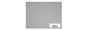
次に、合金粉末の粒度を異ならせた場合の焼結体の特性を比較した。具体的には、分級を行った合金鋼粉を用いた試験片(実施品)と、分級を行わなかった合金鋼粉を用いた試験片(比較品)とを比較した。分級は、合金鋼粉を、目開き180μmの篩を通過させ、粗大な粒子を取り除くことで行われる。その結果を以下の表4に示す。また、実施品及び比較品の断面観察を行った結果、比較品の断面は最大約150μmの粗大空孔(黒い部分が空孔)が観察された{図2(A)参照}。これに対し、実施品の断面には粗大空孔はほとんど観察されなかった{図2(B)参照}。
次に、合金粉末の粒度を異ならせた場合の焼結体の特性を比較した。具体的には、分級を行った合金鋼粉を用いた試験片(実施品)と、分級を行わなかった合金鋼粉を用いた試験片(比較品)とを比較した。分級は、合金鋼粉を、目開き180μmの篩を通過させ、粗大な粒子を取り除くことで行われる。その結果を以下の表4に示す。また、実施品及び比較品の断面観察を行った結果、比較品の断面は最大約150μmの粗大空孔(黒い部分が空孔)が観察された{図2(A)参照}。これに対し、実施品の断面には粗大空孔はほとんど観察されなかった{図2(B)参照}。

表4の結果及び図2から、目開き180μmの篩を通過させて粗大な粒子を除外した合金鋼粉を用いれば、粗大空孔の形成が抑えられることが確認された。
(4)Niの添加量について
合金鋼粉中のNiの添加量を異ならせた試験片の焼結密度及び圧環強さを測定した。その結果を以下の表5及び表6に示す。焼結密度の評価基準は、7.50g/cm3未満のときは×、7.50~7.55g/cm3のときは△、7.55~7.60g/cm3以上のときは○、7.60g/cm3のときは◎とした。圧環強さの評価基準は、上記(1)と同様とした。
合金鋼粉中のNiの添加量を異ならせた試験片の焼結密度及び圧環強さを測定した。その結果を以下の表5及び表6に示す。焼結密度の評価基準は、7.50g/cm3未満のときは×、7.50~7.55g/cm3のときは△、7.55~7.60g/cm3以上のときは○、7.60g/cm3のときは◎とした。圧環強さの評価基準は、上記(1)と同様とした。


表5の結果から、拡散合金鋼粉を用いた場合は、Niの添加量は1.5~2.3wt%、好ましくは1.7~2.2wt%程度とすることが望ましいと言える。また、完全合金鋼粉を用いた場合は、Niの添加量は0.45~0.9wt%、好ましくは0.5~0.7wt%程度とすることが望ましいと言える。
(5)Moの添加量について
合金鋼粉中のMoの添加量を異ならせた試験片の焼結密度及び圧環強さを測定した。その結果を以下の表7及び表8に示す。焼結密度の評価基準は、上記(4)と同様とした。圧環強さの評価基準は、上記(1)と同様とした。
合金鋼粉中のMoの添加量を異ならせた試験片の焼結密度及び圧環強さを測定した。その結果を以下の表7及び表8に示す。焼結密度の評価基準は、上記(4)と同様とした。圧環強さの評価基準は、上記(1)と同様とした。


表7の結果から、拡散合金粉を用いた場合、Moの添加量は0.5~1.5wt%、好ましくは0.8~1.2wt%程度とすることが望ましいと言える。また、完全合金粉を用いた場合、Moの添加量は0.6~1.1wt%、好ましくは0.8~1.1wt%とすることが望ましいと言える。
Claims (10)
- 合金鋼粉及び黒鉛粉末を含む混合粉末を用いて形成された焼結機械部品であって、
前記合金鋼粉が拡散合金鋼粉であり、前記合金鋼粉100wt%に対して前記黒鉛粉末が0.05~0.35wt%であり、前記黒鉛粉末の平均粒子径が8μm以下であり、密度が7.5g/cm3以上である焼結機械部品。 - 合金鋼粉及び黒鉛粉末を含む混合粉末を用いて形成された焼結機械部品であって、
前記合金鋼粉が完全合金鋼粉であり、前記合金鋼粉100wt%に対して前記黒鉛粉末が0.15~0.35wt%であり、前記黒鉛粉末の平均粒子径が8μm以下であり、密度が7.5g/cm3以上である焼結機械部品。 - 前記合金鋼粉が、目開き180μmの篩を通過した粉末である請求項1又は2記載の焼結機械部品。
- 前記合金鋼粉が、Fe-Mo合金の周囲にNiが拡散付着した拡散合金鋼粉である請求項1記載の焼結機械部品。
- 前記拡散合金鋼粉が、Niを1.5~2.3wt%、Moを0.5~1.5wt%含み、残部がFe及び不可避不純物からなる請求項4記載の焼結機械部品。
- 前記合金鋼粉が、Fe-Mo-Ni完全合金鋼粉である請求項2記載の焼結機械部品。
- 前記完全合金鋼粉が、Niを0.45~0.9wt%、Moを0.6~1.1wt%含み、残部がFe及び不可避不純物からなる請求項6記載の焼結機械部品。
- ギヤもしくはカムとして使用される請求項1~7の何れかに記載の焼結機械部品。
- 拡散合金鋼粉100wt%に対して、平均粒子径が8μm以下の黒鉛粉末を0.05~0.35wt%混合して混合粉末を得る混合工程と、前記混合粉末を圧縮成形して圧粉体を得る圧粉工程と、前記圧粉体を所定の焼結温度で焼結して、密度が7.5g/cm3以上の焼結体を得る焼結工程とを含む焼結機械部品の製造方法。
- 完全合金鋼粉100wt%に対して、平均粒子径が8μm以下の黒鉛粉末を0.15~0.35wt%混合して混合粉末を得る混合工程と、前記混合粉末を圧縮成形して圧粉体を得る圧粉工程と、前記圧粉体を所定の焼結温度で焼結して、密度が7.5g/cm3以上の焼結体を得る焼結工程とを含む焼結機械部品の製造方法。
Priority Applications (3)
| Application Number | Priority Date | Filing Date | Title |
|---|---|---|---|
| US14/901,887 US10107376B2 (en) | 2013-07-02 | 2014-06-03 | Sintered machine part and method of manufacturing the same |
| CN201480035641.9A CN105324504A (zh) | 2013-07-02 | 2014-06-03 | 烧结机械部件及其制造方法 |
| EP14819452.5A EP3018228A4 (en) | 2013-07-02 | 2014-06-03 | Sintered mechanical component and manufacturing method therefor |
Applications Claiming Priority (2)
| Application Number | Priority Date | Filing Date | Title |
|---|---|---|---|
| JP2013-139080 | 2013-07-02 | ||
| JP2013139080A JP6309215B2 (ja) | 2013-07-02 | 2013-07-02 | 焼結機械部品の製造方法及びこれに用いる混合粉末 |
Publications (1)
| Publication Number | Publication Date |
|---|---|
| WO2015001894A1 true WO2015001894A1 (ja) | 2015-01-08 |
Family
ID=52143479
Family Applications (1)
| Application Number | Title | Priority Date | Filing Date |
|---|---|---|---|
| PCT/JP2014/064707 WO2015001894A1 (ja) | 2013-07-02 | 2014-06-03 | 焼結機械部品及びその製造方法 |
Country Status (5)
| Country | Link |
|---|---|
| US (1) | US10107376B2 (ja) |
| EP (1) | EP3018228A4 (ja) |
| JP (1) | JP6309215B2 (ja) |
| CN (1) | CN105324504A (ja) |
| WO (1) | WO2015001894A1 (ja) |
Cited By (3)
| Publication number | Priority date | Publication date | Assignee | Title |
|---|---|---|---|---|
| WO2015111338A1 (ja) * | 2014-01-22 | 2015-07-30 | Ntn株式会社 | 焼結機械部品及びその製造方法 |
| WO2016114235A1 (ja) * | 2015-01-15 | 2016-07-21 | Ntn株式会社 | 電動式直動アクチュエータおよび電動式ブレーキ装置 |
| WO2019021935A1 (ja) * | 2017-07-26 | 2019-01-31 | 住友電気工業株式会社 | 焼結部材 |
Families Citing this family (3)
| Publication number | Priority date | Publication date | Assignee | Title |
|---|---|---|---|---|
| CN105899315A (zh) * | 2014-01-22 | 2016-08-24 | Ntn株式会社 | 烧结机械部件及其制造方法 |
| CN106270527A (zh) * | 2016-08-05 | 2017-01-04 | 海安县鹰球粉末冶金有限公司 | 镍合金汽车启动电机行星齿轮及其制造方法 |
| KR20220114262A (ko) * | 2021-02-08 | 2022-08-17 | 현대자동차주식회사 | 피스톤핀 및 이의 제조 방법 |
Citations (9)
| Publication number | Priority date | Publication date | Assignee | Title |
|---|---|---|---|---|
| JPH04337001A (ja) | 1991-05-10 | 1992-11-25 | Kobe Steel Ltd | 粉末冶金用低合金鋼粉及びその焼結成形体並びに調質成形体 |
| JPH0820849A (ja) * | 1994-07-07 | 1996-01-23 | Daido Steel Co Ltd | ステンレス鋼粉末焼結体およびその製造方法 |
| JPH09279204A (ja) * | 1996-04-17 | 1997-10-28 | Kobe Steel Ltd | 粉末冶金用鉄系混合粉末およびこれを用いた焼結体の製法 |
| JP2004232079A (ja) * | 2002-05-21 | 2004-08-19 | Jfe Steel Kk | 粉末冶金用副原料粉末および粉末冶金用鉄基粉末混合物ならびにそれらの製造方法 |
| JP2007537359A (ja) | 2004-05-12 | 2007-12-20 | ホーガナス エービー | 焼結金属部品とその製造法 |
| JP2008169460A (ja) * | 2006-02-15 | 2008-07-24 | Jfe Steel Kk | 鉄基粉末混合物ならびに鉄基粉末成形体および鉄基粉末焼結体の製造方法 |
| JP2009221576A (ja) * | 2008-03-18 | 2009-10-01 | Jfe Steel Corp | 鉄基粉末混合物 |
| JP2009263697A (ja) * | 2008-04-23 | 2009-11-12 | Jfe Steel Corp | 焼結鋼の製造方法 |
| WO2014103999A1 (ja) * | 2012-12-28 | 2014-07-03 | 株式会社神戸製鋼所 | 高疲労強度焼結体用プレアロイ型鋼粉および浸炭焼入れ材 |
Family Cites Families (11)
| Publication number | Priority date | Publication date | Assignee | Title |
|---|---|---|---|---|
| JPS487967Y1 (ja) | 1970-05-01 | 1973-03-01 | ||
| JPH0694562B2 (ja) * | 1987-09-30 | 1994-11-24 | 川崎製鉄株式会社 | 複合合金鋼粉および焼結合金鋼の製造方法 |
| JPH09202934A (ja) * | 1996-01-26 | 1997-08-05 | Sumitomo Metal Mining Co Ltd | ステンレス鋼焼結体の製造方法 |
| WO2002022903A1 (fr) * | 1999-03-30 | 2002-03-21 | Kawasaki Steel Corporation | Poudre melangee a base de fer destinee a des pieces frittees a resistance elevee |
| JP3869620B2 (ja) * | 1999-04-16 | 2007-01-17 | 株式会社日立製作所 | 合金鋼粉成形素材と合金鋼粉加工体及び合金鋼粉成形素材の製造方法 |
| US6503443B1 (en) * | 1999-04-16 | 2003-01-07 | Unisia Jecs Corporation | Metallic powder molding material and its re-compression molded body and sintered body obtained from the re-compression molded body and production methods thereof |
| JP4702758B2 (ja) * | 2000-04-11 | 2011-06-15 | 日立粉末冶金株式会社 | サイレントチェーン用焼結スプロケットおよびその製造方法 |
| JP2004218041A (ja) * | 2003-01-17 | 2004-08-05 | Jfe Steel Kk | 焼結部材及びその製造方法 |
| GB0407539D0 (en) * | 2004-04-02 | 2004-05-05 | Atomising Systems Ltd | Making sintered iron based alloy parts by using boron-containing master alloys |
| JP5552031B2 (ja) * | 2010-11-09 | 2014-07-16 | 株式会社神戸製鋼所 | 粉末冶金用混合粉末 |
| CN105899315A (zh) | 2014-01-22 | 2016-08-24 | Ntn株式会社 | 烧结机械部件及其制造方法 |
-
2013
- 2013-07-02 JP JP2013139080A patent/JP6309215B2/ja active Active
-
2014
- 2014-06-03 WO PCT/JP2014/064707 patent/WO2015001894A1/ja active Application Filing
- 2014-06-03 EP EP14819452.5A patent/EP3018228A4/en not_active Withdrawn
- 2014-06-03 US US14/901,887 patent/US10107376B2/en active Active
- 2014-06-03 CN CN201480035641.9A patent/CN105324504A/zh active Pending
Patent Citations (9)
| Publication number | Priority date | Publication date | Assignee | Title |
|---|---|---|---|---|
| JPH04337001A (ja) | 1991-05-10 | 1992-11-25 | Kobe Steel Ltd | 粉末冶金用低合金鋼粉及びその焼結成形体並びに調質成形体 |
| JPH0820849A (ja) * | 1994-07-07 | 1996-01-23 | Daido Steel Co Ltd | ステンレス鋼粉末焼結体およびその製造方法 |
| JPH09279204A (ja) * | 1996-04-17 | 1997-10-28 | Kobe Steel Ltd | 粉末冶金用鉄系混合粉末およびこれを用いた焼結体の製法 |
| JP2004232079A (ja) * | 2002-05-21 | 2004-08-19 | Jfe Steel Kk | 粉末冶金用副原料粉末および粉末冶金用鉄基粉末混合物ならびにそれらの製造方法 |
| JP2007537359A (ja) | 2004-05-12 | 2007-12-20 | ホーガナス エービー | 焼結金属部品とその製造法 |
| JP2008169460A (ja) * | 2006-02-15 | 2008-07-24 | Jfe Steel Kk | 鉄基粉末混合物ならびに鉄基粉末成形体および鉄基粉末焼結体の製造方法 |
| JP2009221576A (ja) * | 2008-03-18 | 2009-10-01 | Jfe Steel Corp | 鉄基粉末混合物 |
| JP2009263697A (ja) * | 2008-04-23 | 2009-11-12 | Jfe Steel Corp | 焼結鋼の製造方法 |
| WO2014103999A1 (ja) * | 2012-12-28 | 2014-07-03 | 株式会社神戸製鋼所 | 高疲労強度焼結体用プレアロイ型鋼粉および浸炭焼入れ材 |
Non-Patent Citations (1)
| Title |
|---|
| See also references of EP3018228A4 |
Cited By (10)
| Publication number | Priority date | Publication date | Assignee | Title |
|---|---|---|---|---|
| WO2015111338A1 (ja) * | 2014-01-22 | 2015-07-30 | Ntn株式会社 | 焼結機械部品及びその製造方法 |
| WO2016114235A1 (ja) * | 2015-01-15 | 2016-07-21 | Ntn株式会社 | 電動式直動アクチュエータおよび電動式ブレーキ装置 |
| JP2016133126A (ja) * | 2015-01-15 | 2016-07-25 | Ntn株式会社 | 電動式直動アクチュエータおよび電動式ブレーキ装置 |
| CN107250594A (zh) * | 2015-01-15 | 2017-10-13 | Ntn株式会社 | 电动式直动促动器和电动式制动装置 |
| US10634202B2 (en) | 2015-01-15 | 2020-04-28 | Ntn Corporation | Electric linear motion actuator and electromechanical brake system |
| CN107250594B (zh) * | 2015-01-15 | 2020-05-05 | Ntn株式会社 | 电动式直动促动器和电动式制动装置 |
| WO2019021935A1 (ja) * | 2017-07-26 | 2019-01-31 | 住友電気工業株式会社 | 焼結部材 |
| JPWO2019021935A1 (ja) * | 2017-07-26 | 2020-05-28 | 住友電気工業株式会社 | 焼結部材 |
| JP7181871B2 (ja) | 2017-07-26 | 2022-12-01 | 住友電気工業株式会社 | 焼結部材 |
| JP7374269B2 (ja) | 2017-07-26 | 2023-11-06 | 住友電気工業株式会社 | 焼結部材 |
Also Published As
| Publication number | Publication date |
|---|---|
| JP2015010272A (ja) | 2015-01-19 |
| US10107376B2 (en) | 2018-10-23 |
| JP6309215B2 (ja) | 2018-04-11 |
| US20160369881A1 (en) | 2016-12-22 |
| CN105324504A (zh) | 2016-02-10 |
| EP3018228A1 (en) | 2016-05-11 |
| EP3018228A4 (en) | 2017-03-01 |
Similar Documents
| Publication | Publication Date | Title |
|---|---|---|
| WO2015001894A1 (ja) | 焼結機械部品及びその製造方法 | |
| JP5504278B2 (ja) | 拡散合金化された鉄又は鉄基粉末を製造する方法、拡散合金化粉末、該拡散合金化粉末を含む組成物、及び該組成物から製造した成形され、焼結された部品 | |
| JP6227903B2 (ja) | 粉末冶金用合金鋼粉および鉄基焼結体の製造方法 | |
| JP5949952B2 (ja) | 鉄基焼結体の製造方法 | |
| JP6688287B2 (ja) | プレアロイ鉄基粉末、プレアロイ鉄基粉末を含有する鉄基粉末混合物、及び鉄基粉末混合物からプレス成形および焼結した部品を製造する方法 | |
| JP5999285B1 (ja) | 粉末冶金用鉄基合金粉末および焼結鍛造部材 | |
| JP5929967B2 (ja) | 粉末冶金用合金鋼粉 | |
| US20200208244A1 (en) | Sintered material | |
| EP3097999A1 (en) | Sintered machine part and manufacturing method thereof | |
| JP6819624B2 (ja) | 粉末冶金用鉄基混合粉末およびその製造方法ならびに引張強さと耐衝撃性に優れた焼結体 | |
| JP6155894B2 (ja) | 鉄基焼結材およびその製造方法 | |
| JP6444621B2 (ja) | 焼結機械部品 | |
| JP2014177664A (ja) | 成形用粉末、潤滑剤濃化粉末および金属部材の製造方法 | |
| JP6743720B2 (ja) | 粉末冶金用鉄基混合粉末およびその製造方法ならびに引張強さと耐衝撃性に優れた焼結体 | |
| JP6391954B2 (ja) | 焼結機械部品及びその製造方法 | |
| JP7036216B2 (ja) | 鉄基合金焼結体及び粉末冶金用鉄基混合粉 | |
| KR102533137B1 (ko) | 분말 야금용 철기 혼합 분말 및 철기 소결체 | |
| CN114286872B (zh) | 烧结部件以及烧结部件的制造方法 | |
| WO2015111338A1 (ja) | 焼結機械部品及びその製造方法 | |
| JP2019026880A (ja) | 鍛造材の製造方法 |
Legal Events
| Date | Code | Title | Description |
|---|---|---|---|
| WWE | Wipo information: entry into national phase |
Ref document number: 201480035641.9 Country of ref document: CN |
|
| 121 | Ep: the epo has been informed by wipo that ep was designated in this application |
Ref document number: 14819452 Country of ref document: EP Kind code of ref document: A1 |
|
| WWE | Wipo information: entry into national phase |
Ref document number: 14901887 Country of ref document: US |
|
| NENP | Non-entry into the national phase |
Ref country code: DE |
|
| WWE | Wipo information: entry into national phase |
Ref document number: 2014819452 Country of ref document: EP |