WO2014208041A1 - 車両用無線給電システム、車両側無線給電システム及び携帯機器 - Google Patents
車両用無線給電システム、車両側無線給電システム及び携帯機器 Download PDFInfo
- Publication number
- WO2014208041A1 WO2014208041A1 PCT/JP2014/003217 JP2014003217W WO2014208041A1 WO 2014208041 A1 WO2014208041 A1 WO 2014208041A1 JP 2014003217 W JP2014003217 W JP 2014003217W WO 2014208041 A1 WO2014208041 A1 WO 2014208041A1
- Authority
- WO
- WIPO (PCT)
- Prior art keywords
- wireless power
- power supply
- vehicle
- power feeding
- unit
- Prior art date
- Legal status (The legal status is an assumption and is not a legal conclusion. Google has not performed a legal analysis and makes no representation as to the accuracy of the status listed.)
- Ceased
Links
Images








Classifications
-
- B—PERFORMING OPERATIONS; TRANSPORTING
- B60—VEHICLES IN GENERAL
- B60L—PROPULSION OF ELECTRICALLY-PROPELLED VEHICLES; SUPPLYING ELECTRIC POWER FOR AUXILIARY EQUIPMENT OF ELECTRICALLY-PROPELLED VEHICLES; ELECTRODYNAMIC BRAKE SYSTEMS FOR VEHICLES IN GENERAL; MAGNETIC SUSPENSION OR LEVITATION FOR VEHICLES; MONITORING OPERATING VARIABLES OF ELECTRICALLY-PROPELLED VEHICLES; ELECTRIC SAFETY DEVICES FOR ELECTRICALLY-PROPELLED VEHICLES
- B60L58/00—Methods or circuit arrangements for monitoring or controlling batteries or fuel cells, specially adapted for electric vehicles
- B60L58/10—Methods or circuit arrangements for monitoring or controlling batteries or fuel cells, specially adapted for electric vehicles for monitoring or controlling batteries
- B60L58/12—Methods or circuit arrangements for monitoring or controlling batteries or fuel cells, specially adapted for electric vehicles for monitoring or controlling batteries responding to state of charge [SoC]
-
- B—PERFORMING OPERATIONS; TRANSPORTING
- B60—VEHICLES IN GENERAL
- B60L—PROPULSION OF ELECTRICALLY-PROPELLED VEHICLES; SUPPLYING ELECTRIC POWER FOR AUXILIARY EQUIPMENT OF ELECTRICALLY-PROPELLED VEHICLES; ELECTRODYNAMIC BRAKE SYSTEMS FOR VEHICLES IN GENERAL; MAGNETIC SUSPENSION OR LEVITATION FOR VEHICLES; MONITORING OPERATING VARIABLES OF ELECTRICALLY-PROPELLED VEHICLES; ELECTRIC SAFETY DEVICES FOR ELECTRICALLY-PROPELLED VEHICLES
- B60L53/00—Methods of charging batteries, specially adapted for electric vehicles; Charging stations or on-board charging equipment therefor; Exchange of energy storage elements in electric vehicles
- B60L53/10—Methods of charging batteries, specially adapted for electric vehicles; Charging stations or on-board charging equipment therefor; Exchange of energy storage elements in electric vehicles characterised by the energy transfer between the charging station and the vehicle
- B60L53/12—Inductive energy transfer
- B60L53/126—Methods for pairing a vehicle and a charging station, e.g. establishing a one-to-one relation between a wireless power transmitter and a wireless power receiver
-
- H—ELECTRICITY
- H02—GENERATION; CONVERSION OR DISTRIBUTION OF ELECTRIC POWER
- H02J—ELECTRIC POWER NETWORKS; CIRCUIT ARRANGEMENTS OR SYSTEMS FOR SUPPLYING OR DISTRIBUTING ELECTRIC POWER; SYSTEMS FOR STORING ELECTRIC ENERGY
- H02J50/00—Circuit arrangements or systems for wireless supply or distribution of electric power
- H02J50/10—Circuit arrangements or systems for wireless supply or distribution of electric power using inductive coupling
-
- H—ELECTRICITY
- H02—GENERATION; CONVERSION OR DISTRIBUTION OF ELECTRIC POWER
- H02J—ELECTRIC POWER NETWORKS; CIRCUIT ARRANGEMENTS OR SYSTEMS FOR SUPPLYING OR DISTRIBUTING ELECTRIC POWER; SYSTEMS FOR STORING ELECTRIC ENERGY
- H02J50/00—Circuit arrangements or systems for wireless supply or distribution of electric power
- H02J50/10—Circuit arrangements or systems for wireless supply or distribution of electric power using inductive coupling
- H02J50/12—Circuit arrangements or systems for wireless supply or distribution of electric power using inductive coupling of the resonant type
-
- H—ELECTRICITY
- H02—GENERATION; CONVERSION OR DISTRIBUTION OF ELECTRIC POWER
- H02J—ELECTRIC POWER NETWORKS; CIRCUIT ARRANGEMENTS OR SYSTEMS FOR SUPPLYING OR DISTRIBUTING ELECTRIC POWER; SYSTEMS FOR STORING ELECTRIC ENERGY
- H02J50/00—Circuit arrangements or systems for wireless supply or distribution of electric power
- H02J50/40—Circuit arrangements or systems for wireless supply or distribution of electric power using two or more transmitting or receiving devices
-
- H—ELECTRICITY
- H02—GENERATION; CONVERSION OR DISTRIBUTION OF ELECTRIC POWER
- H02J—ELECTRIC POWER NETWORKS; CIRCUIT ARRANGEMENTS OR SYSTEMS FOR SUPPLYING OR DISTRIBUTING ELECTRIC POWER; SYSTEMS FOR STORING ELECTRIC ENERGY
- H02J50/00—Circuit arrangements or systems for wireless supply or distribution of electric power
- H02J50/70—Circuit arrangements or systems for wireless supply or distribution of electric power involving the reduction of electric, magnetic or electromagnetic leakage fields
-
- H—ELECTRICITY
- H02—GENERATION; CONVERSION OR DISTRIBUTION OF ELECTRIC POWER
- H02J—ELECTRIC POWER NETWORKS; CIRCUIT ARRANGEMENTS OR SYSTEMS FOR SUPPLYING OR DISTRIBUTING ELECTRIC POWER; SYSTEMS FOR STORING ELECTRIC ENERGY
- H02J50/00—Circuit arrangements or systems for wireless supply or distribution of electric power
- H02J50/80—Circuit arrangements or systems for wireless supply or distribution of electric power involving the exchange of data, concerning supply or distribution of electric power, between transmitting devices and receiving devices
-
- H—ELECTRICITY
- H02—GENERATION; CONVERSION OR DISTRIBUTION OF ELECTRIC POWER
- H02J—ELECTRIC POWER NETWORKS; CIRCUIT ARRANGEMENTS OR SYSTEMS FOR SUPPLYING OR DISTRIBUTING ELECTRIC POWER; SYSTEMS FOR STORING ELECTRIC ENERGY
- H02J50/00—Circuit arrangements or systems for wireless supply or distribution of electric power
- H02J50/90—Circuit arrangements or systems for wireless supply or distribution of electric power involving detection or optimisation of position, e.g. alignment
-
- H—ELECTRICITY
- H02—GENERATION; CONVERSION OR DISTRIBUTION OF ELECTRIC POWER
- H02J—ELECTRIC POWER NETWORKS; CIRCUIT ARRANGEMENTS OR SYSTEMS FOR SUPPLYING OR DISTRIBUTING ELECTRIC POWER; SYSTEMS FOR STORING ELECTRIC ENERGY
- H02J7/00—Circuit arrangements for charging or discharging batteries or for supplying loads from batteries
- H02J7/80—Circuit arrangements for charging or discharging batteries or for supplying loads from batteries including monitoring or indicating arrangements
- H02J7/82—Control of state of charge [SOC]
- H02J7/825—Detection of fully charged condition
-
- H—ELECTRICITY
- H02—GENERATION; CONVERSION OR DISTRIBUTION OF ELECTRIC POWER
- H02J—ELECTRIC POWER NETWORKS; CIRCUIT ARRANGEMENTS OR SYSTEMS FOR SUPPLYING OR DISTRIBUTING ELECTRIC POWER; SYSTEMS FOR STORING ELECTRIC ENERGY
- H02J7/00—Circuit arrangements for charging or discharging batteries or for supplying loads from batteries
- H02J7/80—Circuit arrangements for charging or discharging batteries or for supplying loads from batteries including monitoring or indicating arrangements
- H02J7/82—Control of state of charge [SOC]
-
- Y—GENERAL TAGGING OF NEW TECHNOLOGICAL DEVELOPMENTS; GENERAL TAGGING OF CROSS-SECTIONAL TECHNOLOGIES SPANNING OVER SEVERAL SECTIONS OF THE IPC; TECHNICAL SUBJECTS COVERED BY FORMER USPC CROSS-REFERENCE ART COLLECTIONS [XRACs] AND DIGESTS
- Y02—TECHNOLOGIES OR APPLICATIONS FOR MITIGATION OR ADAPTATION AGAINST CLIMATE CHANGE
- Y02T—CLIMATE CHANGE MITIGATION TECHNOLOGIES RELATED TO TRANSPORTATION
- Y02T10/00—Road transport of goods or passengers
- Y02T10/60—Other road transportation technologies with climate change mitigation effect
- Y02T10/70—Energy storage systems for electromobility, e.g. batteries
-
- Y—GENERAL TAGGING OF NEW TECHNOLOGICAL DEVELOPMENTS; GENERAL TAGGING OF CROSS-SECTIONAL TECHNOLOGIES SPANNING OVER SEVERAL SECTIONS OF THE IPC; TECHNICAL SUBJECTS COVERED BY FORMER USPC CROSS-REFERENCE ART COLLECTIONS [XRACs] AND DIGESTS
- Y02—TECHNOLOGIES OR APPLICATIONS FOR MITIGATION OR ADAPTATION AGAINST CLIMATE CHANGE
- Y02T—CLIMATE CHANGE MITIGATION TECHNOLOGIES RELATED TO TRANSPORTATION
- Y02T10/00—Road transport of goods or passengers
- Y02T10/60—Other road transportation technologies with climate change mitigation effect
- Y02T10/7072—Electromobility specific charging systems or methods for batteries, ultracapacitors, supercapacitors or double-layer capacitors
-
- Y—GENERAL TAGGING OF NEW TECHNOLOGICAL DEVELOPMENTS; GENERAL TAGGING OF CROSS-SECTIONAL TECHNOLOGIES SPANNING OVER SEVERAL SECTIONS OF THE IPC; TECHNICAL SUBJECTS COVERED BY FORMER USPC CROSS-REFERENCE ART COLLECTIONS [XRACs] AND DIGESTS
- Y02—TECHNOLOGIES OR APPLICATIONS FOR MITIGATION OR ADAPTATION AGAINST CLIMATE CHANGE
- Y02T—CLIMATE CHANGE MITIGATION TECHNOLOGIES RELATED TO TRANSPORTATION
- Y02T90/00—Enabling technologies or technologies with a potential or indirect contribution to GHG emissions mitigation
- Y02T90/10—Technologies relating to charging of electric vehicles
- Y02T90/14—Plug-in electric vehicles
Definitions
- the present disclosure relates to a vehicle wireless power supply system applied in a vehicle interior, a vehicle-side wireless power supply system mounted on a vehicle, and a portable device wirelessly powered from the vehicle-side wireless power supply system.
- wireless power feeding system that wirelessly transmits power from a power feeding device to a power receiving device (wireless power feeding) (see, for example, Patent Document 1).
- a power feeding device for wireless power feeding is mounted on the vehicle side, and wireless power feeding is performed from the power feeding facility to the portable device.
- various information related to wireless power feeding such as where the wireless power feeding is possible, whether wireless power feeding is in progress, and to what extent wireless power feeding has been performed.
- the present disclosure has been made in view of the above-described circumstances, and its purpose is to present various information regarding wireless power feeding to a user when wirelessly powering a portable device brought into the vehicle interior.
- Another object of the present invention is to provide a vehicle wireless power feeding system, a vehicle-side wireless power feeding system, and a portable device that can enhance convenience.
- the portable device is equipped with a battery and operates using the electric power stored in the battery as the operating power.
- a vehicle-side wireless power supply system provided in a vehicle includes wireless power supply means that wirelessly supplies power to a wireless power reception means of a portable device.
- the notification means notifies information relating to wireless power feeding from the wireless power feeding means to the wireless power receiving means as wireless power feeding information.
- various information regarding the wireless power feeding from the wireless power feeding means to the wireless power receiving means can be presented to the user, and the convenience can be improved.
- the various types of information related to wireless power supply include information such as where the wireless power supply is possible, whether wireless power supply is being performed, and to what extent wireless power supply has been performed.
- FIG. 1 A diagram showing a display screen of a portable device (part 2)
- FIG. 3 is a diagram showing a display screen of a portable device (part 3)
- FIG. 4 is a diagram showing a display screen of a portable device (No. 4)
- FIG. 5 is a diagram showing a display screen of a portable device (No. 4)
- the vehicular wireless power supply system 1 includes a vehicle-side wireless power supply system 2 mounted on a vehicle and a portable device 3 that can be brought into a vehicle compartment by a user.
- the user is a driver or a passenger who drives the vehicle
- the portable device 3 is a device that is carried and operated by the driver or the passenger, such as a smartphone or a mobile phone.
- the vehicle-side wireless power feeding system 2 includes a power feeding control device 4 and a plurality of power feeding cases 6 connected from the power feeding control device 4 via a power feeding router 5.
- the power supply control device 4 and the power supply router 5 are connected by a power supply cable 7.
- the feeding router 5 and the feeding case 6 are connected by a feeding cable 8.
- the power supply case 6 is a case for storing the mobile device 3 and wirelessly supplying power.
- the power supply case 6 is mounted in a vehicle interior (range that can be reached by the user) so that the user can easily store the mobile device 3. Need to be.
- the power supply control device 4 and the power supply router 5 do not necessarily have to be mounted in the vehicle compartment as long as they are mounted in the vehicle.
- FIG. 1 shows one power feeding router 5, a plurality of power feeding routers 5 may be used. Further, although two power supply cases 6 are shown in FIG. 1, one power supply case 6 may be used, and three or more power supply cases 6 may be used as shown in FIG.
- the power supply cables 7 and 8 may be embedded and laid in the vehicle body in consideration of convenience and aesthetics when the user gets on and off the vehicle, for example.
- the power supply control device 4 includes a control unit 4a, a wide area wireless communication unit 4b, a short-range wireless communication unit 4c, a power reception unit 4d, a power supply power generation unit 4e, a power transmission unit 4f, and a vehicle LAN (Local Area Network). 4g.
- the control unit 4a includes a known microcomputer having a CPU (Central Processing Unit), a ROM (Read Only Memory), a RAM (Random Access Memory), an I / O (Input / Output) bus, and the like. Is executed to control the overall operation of the power supply control device 4 such as communication control and power transmission control.
- the wide area wireless communication unit 4b performs wide area wireless communication with the wide area wireless communication network 9 including the mobile telephone network.
- the short-range wireless communication unit 4c performs short-range wireless communication in accordance with a wireless communication standard such as Bluetooth (registered trademark), WiFi (registered trademark), or wireless LAN (Local Area Network).
- a wireless LAN communication standard for example, there is IEEE 802.11b which performs wireless communication of 11 [Mbps] in a band of 2.4 [GHz] defined by IEEE (American Institute of Electrical and Electronics Engineers).
- the short-range wireless communication unit 4c is provided with a portable device 3 to be described later on the condition that the portable device 3 is brought into the vehicle compartment and the portable device 3 brought into the vehicle compartment is within the communication range of the short-range wireless communication. Short-distance wireless communication is performed with the short-range wireless communication unit 3 c of the device 3.
- the power receiving unit 4d converts the power of a predetermined voltage transmitted from the vehicle battery 10 mounted on the vehicle, and supplies the converted power to each functional block as operating power.
- the feed power generation unit 4e generates feed power for a feed case 6 to be described later to wirelessly feed the mobile device 3, and transmits the generated feed power to the power transmission unit 4f.
- the power transmission unit 4 f receives the power supplied from the power supply generation unit 4 e, the power transmission unit 4 f transmits the received power to the power supply router 5 via the power supply cable 7.
- the vehicle LAN connection unit 4g is connected to a seating sensor 12 provided in each of a driver seat, a passenger seat, a rear seat, and the like via a vehicle LAN11. When the user is seated, each seating sensor 12 outputs a seating detection signal indicating that the user is seated to the vehicle LAN connection unit 4g via the vehicle LAN11.
- the feeding router 5 When the feeding router 5 receives the feeding power transmitted from the power transmission unit 4 f of the feeding control device 4 via the feeding cable 7, the feeding router 5 transmits the received feeding power to the feeding case 6 via the feeding cable 8.
- the power supply case 6 is a case in which the portable device 3 can be stored and wireless power is supplied to the stored portable device 3.
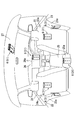
- the power supply case 6 includes, for example, an inner surface portion 21 a of the driver seat door 21, an inner surface portion 22 a of the passenger seat door 22, a rear surface portion 23 a of the driver seat 23, and a rear surface of the passenger seat 24.
- the part 24a, the back part 25a of the center console 25, the front part 26a of the instrument panel 26, and the ceiling part 27 in the passenger compartment are arranged above the driver's seat.
- the power supply case 6 is disposed within a range that can easily be reached by a driver seated in the driver's seat, a passenger seated in the passenger seat, and a passenger seated in the rear seat.
- the power supply case 6 may be disposed in a part other than the part shown in FIG.
- the power supply case 6 includes a power supply control unit 6a, a power reception unit 6b, a wireless power supply unit 6c (wireless power supply unit), a display unit 6d (informing unit), a sound output unit 6e (informing unit), and an electronic tag 6f.
- the power supply control unit 6a is composed of a well-known microcomputer having a CPU, ROM, RAM, I / O bus, etc., and executes a computer program stored in the ROM, etc., and performs power reception control, wireless power supply control, and display. The overall operation of the power supply case 6 such as control and sound output control is controlled.
- the power receiving unit 6 b receives the power supplied from the power supply router 5 via the power supply cable 8.
- the wireless power feeding unit 6c includes a power feeding coil (not shown) and a power feeding capacitor (not shown), and a power receiving coil (not shown) and a power receiving capacitor (not shown) of a wireless power receiving unit 3j of the portable device 3 to be described later. ) And magnetically resonate to wirelessly feed (transmit power) to the portable device 3.
- the power feeding control unit 6a outputs a wireless power feeding control instruction to the wireless power feeding unit 6c on the condition that non-contact communication with the electronic tag 6f is established, and the wireless power feeding unit 6c transmits the wireless power feeding unit 3j to the wireless power receiving unit 3j. Control wireless power feeding.
- the power supply control unit 6a can control the amount of power supplied from the wireless power supply unit 6c.
- the power feeding control unit 6a outputs a display instruction to the display unit 6d and causes the display unit 6d to display information regarding wireless power feeding from the wireless power feeding unit 6 to the wireless power receiving unit 3j as wireless power feeding information. Further, the power supply control unit 6a outputs a sound output instruction to the sound output unit 6e, and displays information related to wireless power supply from the wireless power supply unit 6 to the wireless power reception unit 3j on the display unit 6d as wireless power supply information.
- the wireless power supply information is information on whether or not wireless power supply is possible, information on the amount of power supplied by wireless power supply, information on the charge amount of the battery 3l of the portable device 3 described later, and information on whether or not wireless power supply is normal. Etc.
- the magnetic field resonance method that wirelessly feeds using magnetic field resonance is used, but the radio wave method that wirelessly feeds power as electromagnetic waves, the electromagnetic induction method that wirelessly feeds using induced magnetic flux as a medium, An electric field coupling method in which electric power is supplied by using an electric field may be used.
- the power supply control device 4 and the power supply case 6 can perform power line communication (PLC) between them.
- the data communication method is, for example, an Orthogonal Frequency Division Multiplexing (OFDM) method.
- the portable device 3 includes a control unit 3a, a wide-area wireless communication unit 3b, a short-range wireless communication unit 3c, an audio input unit 3d, an audio output unit 3e, an operation unit 3f, and a display unit 3g (informing means). , A storage unit 3h, a position specifying unit 3i, a wireless power reception unit 3j (wireless power reception means), a power reception control unit 3k, and a battery 3l.
- the control unit 3a is composed of a well-known microcomputer having a CPU, ROM, RAM, I / O bus, etc., and executes a computer program stored in the ROM, etc., and performs communication control, voice call control, data management. Controls overall operations of the portable device 3 such as control, wireless power feeding control, display control, sound output control, and the like.
- the wide area wireless communication unit 3b performs wide area wireless communication with the wide area wireless communication network 9 described above.
- the short-range wireless communication unit 3c performs short-range wireless communication according to a wireless communication standard such as Bluetooth (registered trademark), WiFi (registered trademark), or wireless LAN.
- the short-range wireless communication unit 3c includes the above-described power supply control device 4 on the condition that the portable device 3 is brought into the vehicle compartment and the portable device 3 brought into the vehicle compartment is within the communication range of the short-range wireless communication. Short-distance wireless communication is performed with the short-range wireless communication unit 4c.
- the voice input unit 3d inputs voice from outside.
- the audio output unit 3e outputs audio to the outside.
- the control unit 3a receives the input voice from the wide area wireless communication unit 3b as a transmission voice.
- the voice transmitted from the other party is received by the wide area wireless communication unit 3b
- the received voice is output as the received voice from the voice output unit 3c.
- the operation unit 3f includes mechanical keys arranged on the main body of the mobile device 3 and touch keys displayed on the display unit 3g. When the user operates the keys, an operation signal indicating the operation is transmitted to the control unit 3a. Output to.
- the position specifying unit 3 i has, for example, a GPS (Global Positioning System) receiver, and specifies the position of the mobile device 3.
- GPS Global Positioning System
- the wireless power receiving unit 3j rectifies a high frequency generated by magnetic field resonance with the wireless power feeding unit 6c of the power supply case 6 to generate a direct current, converts the generated direct current into electric power, and outputs the power to the power reception control unit 3k. .
- the power reception control unit 3k When receiving power from the wireless power receiving unit 3j, the power reception control unit 3k outputs the input power to the battery 3l.
- the battery 3l is, for example, a lithium ion battery, and is detachably attached to the main body. The battery 3l supplies the stored power to each functional block as operating power, and when the power is input from the power reception control unit 3k, the battery 3l charges the input power (additional charging).
- the power supply case 6 includes a lid-type power supply case 31 and a lock-type power supply case 51 according to the shape thereof.
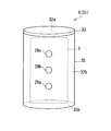
- the power supply case 31 with a lid member has a shape for storing the portable device 3 in a vertical position.
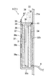
- the power supply case 31 with a lid member is reciprocally rotated between an open position and a closed position with a rotation shaft 41 as a rotation center with respect to the case body 32 and the case body 32 (arrows).
- a lid member 33 (direction A1, A2).
- the lid member 33 opens the opening 32a of the case main body 32 in the open position, and closes the opening 32a of the case main body 32 in the closed position, and switches between the open state and the closed state of the opening 32a.
- the case main body 32 has an elliptical cross section, and has a side surface portion 32b and a bottom surface portion 32c forming a curved surface.
- the power supply case 31 with a lid member is attached so that the rear outer side of the side surface portion 32b faces the inner side surface portion of the door and the rear surface portion of the seat (in FIG. 4, for example, the inner side surface portion 21a of the driver's seat door 21 is shown. ).
- a wireless power feeding circuit unit 34 is provided inside the back surface of the side surface portion 32b.
- the wireless power supply circuit unit 34 incorporates the power supply control unit 6a, the power receiving unit 6b, the wireless power supply unit 6c (including a power supply coil and a power supply capacitor), and the power supply cable 8 is connected.
- the feeding power transmitted from the feeding router 5 is received by the wireless feeding circuit unit 34 via the feeding cable 8.
- Shielding members 35 for shielding electromagnetic waves are provided at the front side inner side, side side inner side, and bottom side inner side of the side part 32b. Further, a shielding member 36 is also provided on the lower surface portion of the lid member 33.
- a gap between the wireless power feeding circuit unit 34 and the shielding member 35 in the case main body 32 is a storage space 37 in which the mobile device 3 can be stored.
- the wireless power supply unit 6c of the power supply case 6 and the wireless power reception unit 3j of the mobile device 3 face each other, and wireless communication from the wireless power supply unit 6c to the wireless power reception unit 3j is performed. Power can be supplied.
- the lid member 33 incorporates a chip 38 including the above-described electronic tag 6f. Further, three LEDs 39a to 39c constituting the display section 6d are arranged on the front outer side of the side surface section 32b.
- the overall shape of the power supply case 31 with a lid member may be determined in accordance with, for example, the shape of the curved surface of the door or the curved surface of the seat. Also, as shown in FIG. 5, for example, a plurality of (three are shown in FIG. 5) power supply cases 31 with lid members may be arranged on the lining 40 of one door.
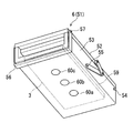
- the lock-type power supply case 51 has a shape for storing the mobile device 3 horizontally, and is disposed, for example, on the ceiling portion 27 in the vehicle interior.
- the lock-type power supply case 51 reciprocally rotates between a fixed position and a non-fixed position with a rotation shaft 54 as a rotation center with respect to the fixed member 52 (arrow B1). , B2 direction), a connecting member 55 for connecting the fixed member 52 and the movable member 53, and a reciprocating movement between the locking position and the non-locking position with respect to the fixing member 52 about the rotation shaft 57 as a rotation center.
- a lock member 56 that rotates (in the directions of arrows C1 and C2).
- the lock-type power supply case 51 is attached so that the back surface (upper surface side) of the fixing member 52 faces the ceiling portion 27 in the vehicle interior.
- a wireless power feeding circuit unit 58 is provided on the front side (lower surface side) of the fixing member 52.
- the wireless power feeding circuit unit 58 includes a power feeding control unit 6a, a power receiving unit 6b, a wireless power feeding unit 6c, and the like, and a power feeding cable 8 is connected thereto. The feeding power transmitted from the feeding router 5 is received by the wireless feeding circuit unit 58 via the feeding cable 8.
- a storage space 59 in which the portable device 3 can be stored.
- the storage space 59 is largely opened.
- the mobile device 3 is disposed so as to face the wireless power feeding circuit unit 58, the movable member 53 is rotated from the non-fixed position to the fixed position, and the lock member 56 is rotated from the non-locked position to the locked position. Is fixed at a fixed position, whereby the portable device 3 is stored in the storage space 59 in a fixed state.
- the wireless power supply unit 6c of the power supply case 6 and the wireless power reception unit 3j of the mobile device 3 face each other, and wireless communication from the wireless power supply unit 6c to the wireless power reception unit 3j is performed. Power can be supplied.
- the movable member 53 incorporates a chip 61 including the electronic tag 6f described above.
- three LEDs 60a to 60c constituting the display unit 6d described above are arranged on the front outer side of the movable member 53.
- the lock-type power supply case 51 is also provided with a shielding member (not shown) for shielding electromagnetic waves, similar to the above-described power supply case 31 with a lid member.
- the mobile device 3 is stored horizontally in the storage space 59, the movable member 53 is moved from the non-fixed position to the fixed position, and the lock member 56 is moved from the non-locked position to the locked position to be movable.
- the member 53 is fixed at a fixed position, non-contact communication is established between the power supply control unit 6a and the electronic tag 6f, and wireless power supply from the wireless power supply unit 6c to the wireless power reception unit 3j of the portable device 3 can be started. It becomes.
- the movable member 53 is moved from the non-fixed position to the fixed position, and the lock member 56 is moved from the non-locked position to the locked position, and the movable member 53 is fixed at the fixed position, the portable device 3 becomes the shielding member.
- the overall shape of the lock-type power supply case 51 may also be determined in accordance with, for example, the shape of the curved surface of the ceiling.
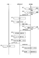
- control unit 3a regularly monitors the remaining capacity of battery 3l.
- the control unit 3a determines that the remaining capacity of the battery 3l has decreased to a predetermined value (for example, 20% of the full capacity) (A1: YES)
- the control unit 3a sends a power supply request request signal from the wide area wireless communication unit 3b via the wide area communication network 9.
- a predetermined value for example, 20% of the full capacity
- the control unit 3a sends a power supply request request signal from the wide area wireless communication unit 3b via the wide area communication network 9.
- the control unit 3a registers information (address on the network, etc.) of the transmission destination of the power supply request request signal in the mobile device 3 in advance, so that the control unit 3a outputs the power supply request request signal.
- the power supply request request signal transmitted from the mobile device 3 to the power supply control device 4 includes power supply request information indicating specifications (wireless power supply method, resonance frequency, etc.) regarding the wireless power supply of the mobile device 3.
- the control unit 4 a when the control unit 4 a receives the power supply request request signal transmitted from the mobile device 3 by the wide area wireless communication unit 4 b via the wide area communication network 9, the power supply request information is obtained from the received power supply request request signal. Is extracted and analyzed (B1). Next, the control unit 4 a causes the use state request signal to be transmitted from the power transmission unit 4 f to all the power supply cases 6 via the power supply router 5.
- the power supply control unit 6a when the power supply control unit 6a receives the usage status request signal transmitted from the power supply control device 4 via the power supply router 5, the power reception unit 6b identifies the usage status at that time (C1). When the power supply control unit 6a specifies the usage status at that time, the power supply control unit 6a transmits a usage status response signal indicating the specified usage status from the power receiving unit 6b to the power supply control device 4 via the power supply router 5. In other words, the power supply control unit 6a stores the portable device 3 at that time, and indicates that the wireless power supply to the portable device 3 is being performed if the portable device 3 is being wirelessly powered. A usage status response signal is transmitted from the power receiving unit 6b to the power supply control device 4.
- the power supply control unit 6a does not store the mobile device 3 at that time, and if the wireless power supply to the mobile device 3 is not being performed, the power supply control unit 6a generates a usage status response signal indicating that the mobile device 3 is not wirelessly powered. Transmission is performed from the power reception unit 6 b to the power supply control device 4.
- the control unit 4 a when the control unit 4 a receives the usage status response signal transmitted from the power supply case 6 via the power supply router 5, the control unit 4 a extracts the usage status from the received usage status response signal. Analyze (B2) and create an answer to the power supply request (B3). In this case, as a response to the power supply request, the control unit 4a creates a power supply availability determination that indicates whether wireless power supply is possible for each power supply case 6, power supply method specifications, power usage information, and the like. Then, the control unit 4a transmits a power supply request response signal including a response to the generated power supply request from the wide area wireless communication unit 4b to the mobile device 3 via the wide area communication network 9.
- the control unit 3a responds to the power supply request from the received power supply request response signal. Answers are extracted and displayed on the display unit 3g (A2).
- the user using the mobile device 3 can perform wireless power supply for each power supply case 6 when the remaining capacity of the battery 3l of the mobile device 3 used by the user decreases to a predetermined value. It is possible to grasp information related to wireless power feeding, such as power feeding availability determination, power feeding method specifications, and power usage. That is, whether or not the user using the portable device 3 has an empty power supply case 6 (there is a power supply case 6 capable of wireless power supply) before getting on the vehicle on which the vehicle-side wireless power supply system 2 is mounted. It is possible to grasp whether or not wireless power feeding to the portable device 3 is possible when the user gets on the vehicle.
- information related to wireless power feeding such as power feeding availability determination, power feeding method specifications, and power usage. That is, whether or not the user using the portable device 3 has an empty power supply case 6 (there is a power supply case 6 capable of wireless power supply) before getting on the vehicle on which the vehicle-side wireless power supply system 2 is mounted. It is possible to grasp whether or not wireless power feeding to the portable device 3 is possible when the user gets on
- the control unit 3a periodically determines whether the short-range wireless communication unit 3c is within the communication range of short-range wireless communication. Monitoring. When the user carrying the mobile device 3 approaches or gets on the vehicle trying to get on, the control unit 3a determines that the short-range wireless communication unit 3c is within the communication range of short-range wireless communication (A11: YES) ), An authentication request signal is transmitted from the short-range wireless communication unit 3 c to the power supply control device 4.
- the control unit 3a Transmission to the power supply control device 4 registered in advance by the user becomes possible.
- the authentication request signal transmitted from the mobile device 3 to the power supply control device 4 includes authentication information necessary for authenticating whether or not the mobile device 3 permits wireless power supply. That is, the power supply control device 4 satisfies a power supply condition such as that the wireless power supply method is adapted, and permits the wireless power supply from the power supply case 6 to the portable device 3 if the authentication result is positive. On the other hand, the power supply control device 4 prohibits wireless power supply from the power supply case 6 to the portable device 3 if the power supply conditions such as the wireless power supply method is not satisfied and the authentication result is negative.
- the control unit 4a In the power feeding control device 4, when the authentication request signal transmitted from the mobile device 3 is received by the short-range wireless communication unit 4c, the control unit 4a extracts authentication information from the received authentication request signal and performs authentication (B11). . When the authentication is completed, the control unit 4a creates an authentication result (B12). If the authentication result is positive, the control unit 4a sends an authentication response signal indicating that the authentication result is positive from the short-range wireless communication unit 4c to the power supply control device. 4 to send. On the other hand, if the authentication result is negative, the power supply control unit 6a transmits an authentication response signal indicating that the authentication result is negative from the short-range wireless communication unit 4c to the power supply control device 4.
- the control unit 3 a extracts and determines an authentication result from the received authentication response signal.
- the control unit 3a determines that the authentication result is positive (A12: YES)
- the short-range wireless communication unit transmits a position specifying signal including position information indicating the position of the mobile device 3 specified by the position specifying unit 3i at that time. 3c is transmitted to the power supply control device 4.
- the control unit 4 a when the short-range wireless communication unit 4 c receives the position specifying signal transmitted from the mobile device 3, the control unit 4 a extracts position information from the received position specifying signal and extracts the position of the mobile device 3. Is specified (B13). Next, the control unit 4a identifies the position of the user in the passenger compartment from the seating detection signal input from the seating sensor 12 to the vehicle LAN connection unit 4g via the vehicle LAN11 (B14).
- control part 4a specifies the seat of the specified user, ie, the seat where the user who is carrying the portable apparatus 3 which requires wireless power feeding is seated, and determines the power supply case 6 to be notified (B15) ). That is, when the control unit 4a determines that the portable device 3 is present in the passenger compartment based on the position specifying signal and determines that the user is seated in the driver's seat based on the seating detection signal, the control unit 4a receives the driver seated in the driver's seat.
- the power supply case 6 arranged in a reachable range is determined as a notification target. Specifically, in the arrangement mode shown in FIG.
- the control unit 4a determines these power supply cases 6 as notification targets.
- the control unit 4a determines that the mobile device 3 is present in the passenger compartment by using the position specifying signal and determines that the user has been seated in the rear seat by using the seating detection signal, the control unit 4a detects from the passenger seated in the rear seat.
- the power supply case 6 arranged in a reachable range is determined as a notification target.
- the control unit 4a determines the power feeding cases 6 as notification targets.
- the control unit 4a determines the power supply case 6 to be notified in this manner, the control unit 4a transmits a notification drive signal from the power transmission unit 4f to the determined power supply case 6 of the notification target via the power supply router 5.
- the control unit 4a transmits a notification drive signal from the power transmission unit 4f to the determined power supply case 6 of the notification target via the power supply router 5.
- the power supply control unit 6 a when the power supply control unit 6 a receives the notification drive signal transmitted from the power supply control device 4 by the power reception unit 6 b via the power supply router 5, the power supply control unit 6 a Performed by the sound output unit 6e (C11). Specifically, the power supply control unit 6a displays a predetermined display pattern on the display unit 6d or outputs a predetermined sound pattern from the sound output unit 6e. If the power supply case 6 is a power supply case 31 with a lid member, the power supply control unit 6a lights and blinks the three LEDs 39a to 39c in accordance with a predetermined lighting / flashing pattern.
- the power supply control unit 6a turns on and blinks the three LEDs 60a to 60c according to a predetermined lighting and blinking pattern. Further, when determining the power supply case 6 to be notified, the control unit 4a causes the short-range wireless communication unit 4c to transmit a notification instruction signal including notification determination information indicating the power supply case 6 determined as the notification target to the portable device 3. .
- the control unit 3a extracts notification determination information from the received notification instruction signal and determines it as a notification target.
- the supplied power supply case 6 is specified (A13).
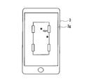
- the control unit 3a causes the display unit 3g to display position information indicating the position of the specified power supply case 6 that can be wirelessly fed (A14).
- the control unit 3a indicates that the mobile device 3 needs to be charged, that the mobile device 3 can be charged, the position of the power supply case 6 that can be wirelessly fed, and the like.
- a display screen is displayed on the display unit 3g.
- the control unit 3a may cause the display unit 3g to display a display screen showing only the position of the power supply case 6 capable of wireless power feeding.
- a display screen showing the position of the power supply case 6 arranged on the inner side surface 21 a of the driver seat door 21 and the front surface portion 26 a of the instrument panel 26 is shown.
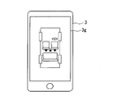
- the control unit 3a captures a captured image obtained by capturing the position of the power supply case 6 capable of wireless power feeding with the camera as shown in FIG.
- a display screen superimposed on may be displayed on the display unit 3g.
- a display screen showing the position of the power supply case 6 disposed on the front part 26a of the instrument panel 26 and the ceiling part 27 in the passenger compartment and above the driver's seat is shown.
- the control unit 3a displays on the display unit 3g a display screen indicating the position of the power supply case 6 that can be wirelessly powered near the seat designated by the user. It may be displayed.
- the display screen which shows the position of is shown.
- the mark indicating the position of the power supply case 6 may be any mark.
- the user using the mobile device 3 can grasp the position of the power supply case 6 that can be supplied within the reach of his / her hand when getting on. That is, the user using the mobile device 3 can grasp the position of the power supply case 6 that can be supplied by performing the notification operation of the power supply case 6g that can supply power without viewing the display screen of the mobile device 3. it can. In addition, the user who uses the mobile device 3 can grasp the position of the power supply case 6 that can supply power by visually observing the display screen of the mobile device 3.
- the control unit 3a determines whether or not the user has performed a predetermined operation after determining that the short-range wireless communication unit 3c is within the communication range of the short-range wireless communication (A11: YES). (A15), and when it is determined that the user has performed a predetermined operation (A15: YES), the authentication request signal is transmitted from the short-range wireless communication unit 3c to the power supply control device 4, and the subsequent processing is performed. You may do it.
- the power supply control unit 6a periodically monitors whether or not a power supply start condition is satisfied.
- the power supply control unit 6a determines that the power supply start condition is satisfied (C21: YES)
- the power supply control unit 6a causes the wireless power supply unit 6c to transmit a power reception availability request signal to the portable device 3.
- the power supply case 6 is a power supply case 31 with a lid member
- the power supply control unit 6a rotates the cover member 33 from the open position to the closed position in a state where the portable device 3 is stored in the storage space 37.
- the power supply control unit 6 a rotates the movable member 53 from the non-fixed position to the fixed position while the mobile device 3 is stored in the storage space 59.
- the member 56 is moved from the non-lock position to the lock position, the movable member 53 is fixed at the fixed position, and the non-contact communication is established between the power supply control unit 6a and the electronic tag 6f, the power supply start condition is satisfied. Is determined.
- the control unit 3a determines whether power can be received at that time (A21).
- the control unit 3a is in a state in which the portable device 3 waits for power reception at that time (for example, the battery 3l is normal), and if the power can be received, the control unit 3a wirelessly receives a power reception propriety response signal indicating that power reception is possible.
- the power is transmitted from the unit 3g to the power supply case 6.
- the control unit 3a indicates that power cannot be received.
- the availability response signal is transmitted from the wireless power receiving unit 3g to the power supply case 6.
- the power supply control unit 6 a when the power supply control unit 6 a receives the power reception propriety response signal transmitted from the mobile device 3, the power supply control unit 6 a specifies power reception propriety from the received power reception propriety response signal.
- the power supply control unit 6a determines that the mobile device 3 can receive power (C22: YES)
- the power supply control unit 6a transmits a power reception preparation request signal from the wireless power supply unit 6c to the mobile device 3.
- the control unit 3 a prepares for receiving power when the wireless power receiving unit 3 j receives the power reception preparation request signal transmitted from the power supply case 6 (A 22). Transmission is performed from the wireless power receiving unit 3g to the power supply case 6.
- the power supply control unit 6a when the power supply control unit 6a receives the power reception preparation response signal transmitted from the mobile device 3, the power supply control unit 6a starts wireless power supply from the wireless power supply unit 6c to the wireless power reception unit 3j of the mobile device 3 (C23, A23). ).
- the power supply control unit 6a transmits a power reception state request signal from the wireless power supply unit 6c to the portable device 3.
- the power supply control unit 6a may perform a notification operation for notifying that the wireless power supply from the wireless power supply unit 6c to the wireless power reception unit 3j of the portable device 3 has been started by the display unit 6d and the sound output unit 6e.
- the control unit 3a specifies the power receiving state (A24), and the power receiving state response signal including the specified receiving state Is transmitted from the wireless power receiving unit 3g to the power supply case 6.
- the power supply control unit 6 a when the power supply control unit 6 a receives the power reception state response signal transmitted from the mobile device 3, the power reception state is extracted from the power reception state response signal and analyzed, and the wireless power supply to the mobile device 3 is normal. It is determined whether or not (C24).
- the power supply control unit 6a monitors the wireless power supply to the mobile device 3 by periodically transmitting the power reception state request signal to the mobile device 3 periodically at a predetermined cycle.
- the power supply control unit 6a wirelessly supplies power from the wireless power supply unit 6c to the wireless power reception unit 3j in this way, as the state of the wireless power supply, for example, the power supply amount, the power supply time, and the charging for the full capacity of the battery 3l
- the display unit 6d and the sound output unit 6e perform a notification operation for reporting information on whether the amount and the state of the wireless power supply are normal or abnormal.
- the power supply control unit 6a displays a predetermined display pattern indicating the information on the display unit 6d or outputs a predetermined sound pattern from the sound output unit 6e.
- the power supply control unit 6a lights and blinks the three LEDs 39a to 39c in accordance with a predetermined lighting / flashing pattern. If the power supply case 6 is a lock-type power supply case 51, the power supply control unit 6a turns on and blinks the three LEDs 60a to 60c according to a predetermined lighting and blinking pattern.
- the power feeding control unit 6a changes from the wireless power feeding unit 6c to the wireless power receiving unit 3j according to, for example, power consumption in a device mounted on the vehicle. Controls the amount of power supplied wirelessly. That is, for example, when the power supply control device 4 acquires the power consumption of an electronic control unit (ECU: Electronic Control Unit) or other in-vehicle device via the vehicle LAN 11, the power supply control unit 6a The amount of power to be wirelessly fed from the wireless power feeding unit 6c to the wireless power receiving unit 3j may be controlled according to the acquired power consumption.
- ECU Electronic Control Unit
- the power supply control unit 6a monitors whether or not the power supply end condition is satisfied, for example, the power supply amount to the portable device 3 has reached a predetermined capacity, the power supply time has reached a predetermined time, and the full capacity of the battery 3l When it is determined that the power supply end condition is satisfied because the amount of charge for the battery reaches a predetermined capacity (C25: YES), the wireless power supply from the wireless power supply unit 6c to the wireless power reception unit 3j of the portable device 3 is ended (C26, A25).
- the power supply control unit 6a may perform a notification operation for notifying that the wireless power supply from the wireless power supply unit 6c to the wireless power reception unit 3j of the portable device 3 is ended by the display unit 6d and the sound output unit 6e.
- the mobile device 3 is housed in the power supply case 6, so that the mobile device 3 can be wirelessly powered from the power supply case 6.
- the mobile device 3 is surrounded by the shielding members 35 and 36 during the period when the power supply case 6 wirelessly supplies power to the mobile device 3. Leakage of electromagnetic waves due to wireless power feeding to the outside is suppressed by the shielding members 35 and 36. Even if the power supply case 6 is a lock-type power supply case 51, the mobile device 3 is surrounded by a shielding member during the period in which the power supply case 6 is wirelessly supplying power to the mobile device 3. Leakage is suppressed by the shielding member.
- the power supply case 6 disposed in the vehicle interior or the portable device 3 carried by the user can wirelessly supply power to the portable device 3 is determined.
- the power supply amount, power supply time, charge amount with respect to the full capacity of the battery 3l, information on whether the state of wireless power supply is normal or abnormal, and the like are reported. Thereby, various information related to wireless power feeding from the power feeding case 6 to the portable device 3 can be presented to the user, and convenience can be improved.
- the power supply case 31 with a lid member includes the shielding members 35 and 36 and the portable device 3 is surrounded by the shielding members 35 and 36 during the period when the portable device 3 is wirelessly fed, Leakage of electromagnetic waves due to power supply can be suppressed by the shielding members 35 and 36, and radiation exposure does not cause a problem.
- the lock-type power supply case 51 is also configured to have a shielding member, and the portable device 3 is surrounded by the shielding member during the period in which the portable device 3 is wirelessly fed. Can be suppressed by the shielding member, and radiation exposure does not become a problem.
- the amount of power supplied from the power supply case 6 to the portable device 3 is controllable, for example, power is supplied from the power supply case 6 to the portable device 3 according to the power consumption of the electronic control device or other in-vehicle devices.
- By controlling the amount of power it is possible to avoid a situation in which the operating power of other in-vehicle devices cannot be secured due to wireless power feeding from the power feeding case 6 to the portable device 3.
- the present disclosure is not limited to the above-described embodiment, and can be modified or expanded as follows. A plurality of modified examples may be combined.
- the display device can provide various information regarding wireless power supply. It may be configured to display.
- a display device for example, while a navigation map is being displayed on the display device, various information relating to wireless power feeding may be displayed in a partial area of the display screen. For example, a pop-up display may be made on the map to start feeding or end feeding.
- the configuration in which both the display unit and the sound output unit notify various information related to wireless power supply has been described.
- the display unit and the sound output unit may notify various information related to wireless power supply. good.
- information related to wireless power feeding it may be configured to notify information on whether or not the procedure for storing the portable device in the power feeding case is normal (for example, whether the portable device is in the vertical direction or the front-back direction is normal).
- the mobile device and an in-vehicle device such as a navigation device mounted on the vehicle may provide various applications.
- the mobile device and the in-vehicle device are configured so that data communication is possible between them, and music data stored in the mobile device is transferred from the mobile device to the in-vehicle device.
- An application that outputs the transferred music data from a speaker attached to the in-vehicle device may be provided.
- a priority is assigned to avoid concentration of power consumption so that the plurality of power supply cases sequentially start wireless power supply according to the priority order. Also good.
Landscapes
- Engineering & Computer Science (AREA)
- Power Engineering (AREA)
- Computer Networks & Wireless Communication (AREA)
- Transportation (AREA)
- Mechanical Engineering (AREA)
- Physics & Mathematics (AREA)
- Electromagnetism (AREA)
- Life Sciences & Earth Sciences (AREA)
- Sustainable Development (AREA)
- Sustainable Energy (AREA)
- Charge And Discharge Circuits For Batteries Or The Like (AREA)
Abstract
Description
(2)車両側無線給電システム2が無線給電可能な給電ケース6を報知する処理
(3)給電ケース6が携帯機器3に無線給電する処理について順次説明する。
携帯機器3において、制御部3aは、電池3lの残容量を定期的に監視している。制御部3aは、電池3lの残容量が所定値(例えば満容量に対する2割)まで低下したと判定すると(A1:YES)、給電依頼要求信号を広域無線通信部3bから広域通信網9を介して給電制御装置4に送信させる。この場合、携帯機器3を使用するユーザが予め給電依頼要求信号の送信先の情報(ネットワーク上のアドレス等)を携帯機器3に登録しておくことで、制御部3aは、給電依頼要求信号を当該ユーザが予め登録しておいた給電制御装置4に送信可能となる。携帯機器3から給電制御装置4に送信される給電依頼要求信号は、携帯機器3の無線給電に関する仕様(無線給電方式、共鳴周波数等)を示す給電依頼情報を含む。
携帯機器3において、制御部3aは、近距離無線通信部3cが近距離無線通信の通信圏内であるか否か定期的に監視している。携帯機器3を携帯したユーザが乗車しようとして車両に近付いたり乗車したりすることで、制御部3aは、近距離無線通信部3cが近距離無線通信の通信圏内であると判定すると(A11:YES)、認証要求信号を近距離無線通信部3cから給電制御装置4に送信させる。この場合も、携帯機器3を使用するユーザが予め認証要求信号の送信先の情報(ネットワーク上のアドレス等)を携帯機器3に登録しておくことで、制御部3aは、認証要求信号を当該ユーザが予め登録しておいた給電制御装置4に送信可能となる。携帯機器3から給電制御装置4に送信される認証要求信号は、無線給電を許可する携帯機器3であるか否かを認証するのに必要な認証情報を含む。即ち、給電制御装置4は、例えば無線給電方式が適合する等の給電条件を満たしており、認証結果が正であれば、給電ケース6から携帯機器3への無線給電を許可する。一方、給電制御装置4は、例えば無線給電方式が適合しない等の給電条件を満たしておらず、認証結果が否であれば、給電ケース6から携帯機器3への無線給電を禁止する。
給電ケース6において、給電制御部6aは、給電開始条件が成立したか否かを定期的に監視している。給電制御部6aは、給電開始条件が成立したと判定すると(C21:YES)、受電可否要求信号を無線給電部6cから携帯機器3に送信させる。給電ケース6が蓋部材付き型の給電ケース31であれば、給電制御部6aは、携帯機器3を収納スペース37に収納した状態で蓋部材33が開放位置から閉鎖位置に回動され、給電制御部6aと電子タグ6fとの間で非接触通信が成立した場合に、給電開始条件が成立したと判定する。給電ケース6がロック型の給電ケース51であれば、給電制御部6aは、携帯機器3を収納スペース59に収納した状態で可動部材53が非固定位置から固定位置に回動され、更に、ロック部材56が非ロック位置からロック位置に移動されて可動部材53が固定位置に固定され、給電制御部6aと電子タグ6fとの間で非接触通信が成立した場合に、給電開始条件が成立したと判定する。
(変形例)
本開示は、上記した実施形態にのみ限定されるものではなく、以下のように変形又は拡張することができる。又、複数の変形例を組み合わせても良い。
Claims (13)
- 電池(3l)を装着し、前記電池に蓄積されている電力を動作電力として動作する携帯機器(3)と、
車両に設けられ、前記携帯機器の無線受電手段(3j)に無線給電する無線給電手段(6c)を有する車両側無線給電システム(2)と、
前記無線給電手段から前記無線受電手段への無線給電に関する情報を無線給電情報として報知する報知手段(6d、6e、3g)と、を備えた車両用無線給電システム(1)。 - 請求項1に記載した車両用無線給電システムにおいて、
前記報知手段は、前記無線給電情報として前記無線給電手段が前記無線受電手段に無線給電可能であるか否かの情報を報知する車両用無線給電システム。 - 請求項1又は2に記載した車両用無線給電システムにおいて、
前記報知手段は、前記無線給電情報として前記無線給電手段が前記無線受電手段に無線給電した給電量の情報を報知する車両用無線給電システム。 - 請求項1から3の何れか一項に記載した車両用無線給電システムにおいて、
前記携帯機器は、前記無線給電手段が前記無線受電手段に無線給電することで前記電池の充電量が変動し、
前記報知手段は、前記無線給電情報として前記無線給電手段が前記無線受電手段に無線給電したことで変動した前記電池の充電量の情報を報知する車両用無線給電システム。 - 請求項1から4の何れか一項に記載した車両用無線給電システムにおいて、
前記報知手段は、前記無線給電手段が前記無線受電手段に無線給電中では、前記無線給電情報として前記無線給電手段から前記無線受電手段への無線給電が正常であるか異常であるかの情報を報知する車両用無線給電システム。 - 請求項1から5の何れか一項に記載した車両用無線給電システムにおいて、
前記報知手段は、前記車両側無線給電システムに設けられている車両用無線給電システム。 - 請求項1から5の何れか一項に記載した車両用無線給電システムにおいて、
前記報知手段は、前記携帯機器に設けられている車両用無線給電システム。 - 請求項1から6の何れか一項に記載した車両用無線給電システムにおいて、
前記無線給電手段は、前記携帯機器を収納可能な給電ケース(6)に設けられ、前記給電ケースが前記携帯機器を収納している状態で前記無線受電手段に無線給電可能である車両用無線給電システム。 - 請求項8に記載した車両用無線給電システムにおいて、
前記無線給電手段は、前記給電ケースが前記携帯機器を収納している状態で所定条件が成立している期間で前記無線受電手段に無線給電可能であり、前記給電ケースが前記携帯機器を収納している状態でも前記所定条件が成立していない期間では前記無線受電手段に無線給電不可能である車両用無線給電システム。 - 請求項9に記載した車両用無線給電システムにおいて、
前記無線給電手段は、無線給電することによる外部への電磁波の漏洩を抑制可能な状態であることを前記所定条件とする車両用無線給電システム。 - 請求項1から10の何れか一項に記載した車両用無線給電システムにおいて、
前記無線給電手段は、前記無線受電手段への給電電力の電力量を制御可能である車両用無線給電システム。 - 車両に設けられている車両側無線給電システム(2)において、
電池(3l)に蓄積されている電力を動作電力として動作する携帯機器(3)の無線受電手段(3j)に無線給電する無線給電手段(6c)と、
前記無線給電手段から前記無線受電手段への無線給電に関する情報を無線給電情報として報知する報知手段(6d、6e)と、を備えた車両側無線給電システム。 - 電池(3l)に蓄積されている電力を動作電力として動作する携帯機器(3)において、
車両に設けられている車両側無線給電システム(2)の無線給電手段(6c)から無線給電される無線受電手段(3j)と、
前記無線給電手段から前記無線受電手段への無線給電に関する情報を無線給電情報として報知する報知手段(3g)と、を備えた携帯機器。
Priority Applications (3)
| Application Number | Priority Date | Filing Date | Title |
|---|---|---|---|
| DE112014002986.6T DE112014002986T5 (de) | 2013-06-25 | 2014-06-17 | Drahtloses Fahrzeugenergiespeisungssystem, fahrzeugseitiges Energiespeisungssystem und tragbare Vorrichtung |
| CN201480035336.XA CN105324910B (zh) | 2013-06-25 | 2014-06-17 | 车辆用无线供电系统、车辆侧无线供电系统及便携机器 |
| US14/900,572 US20160144726A1 (en) | 2013-06-25 | 2014-06-17 | Vehicular wireless power feeding system, vehicle-side power feeding system and portable apparatus |
Applications Claiming Priority (2)
| Application Number | Priority Date | Filing Date | Title |
|---|---|---|---|
| JP2013132626A JP6079473B2 (ja) | 2013-06-25 | 2013-06-25 | 車両用無線給電システム、車両側無線給電システム及び携帯機器 |
| JP2013-132626 | 2013-06-25 |
Publications (1)
| Publication Number | Publication Date |
|---|---|
| WO2014208041A1 true WO2014208041A1 (ja) | 2014-12-31 |
Family
ID=52141409
Family Applications (1)
| Application Number | Title | Priority Date | Filing Date |
|---|---|---|---|
| PCT/JP2014/003217 Ceased WO2014208041A1 (ja) | 2013-06-25 | 2014-06-17 | 車両用無線給電システム、車両側無線給電システム及び携帯機器 |
Country Status (5)
| Country | Link |
|---|---|
| US (1) | US20160144726A1 (ja) |
| JP (1) | JP6079473B2 (ja) |
| CN (1) | CN105324910B (ja) |
| DE (1) | DE112014002986T5 (ja) |
| WO (1) | WO2014208041A1 (ja) |
Families Citing this family (13)
| Publication number | Priority date | Publication date | Assignee | Title |
|---|---|---|---|---|
| KR101535018B1 (ko) * | 2014-04-25 | 2015-07-07 | 현대자동차주식회사 | 무선 충전 정보 표시 장치 및 방법 |
| DE102015224839A1 (de) * | 2015-05-13 | 2016-11-17 | Volkswagen Aktiengesellschaft | Gerätespezifische Anpassung des kabellosen Ladeverhaltens von Mobilgeräten |
| CN109565185B (zh) * | 2016-08-05 | 2022-10-14 | 夏普株式会社 | 通信装置、控制程序以及非接触供电系统 |
| US20230299618A1 (en) * | 2017-05-16 | 2023-09-21 | Wireless Electrical Grid Lan, Wigl Inc. | Wireless communication device and method of using |
| KR102517345B1 (ko) | 2017-12-27 | 2023-04-03 | 삼성전자주식회사 | 차량 내의 모바일 디바이스를 충전하기 위한 시스템 및 방법 |
| JP7004615B2 (ja) * | 2018-06-29 | 2022-01-21 | 三菱重工業株式会社 | 充電システム、充電ステーション、移動体及び充電方法 |
| US11689065B2 (en) * | 2019-02-15 | 2023-06-27 | Honda Motor Co., Ltd. | System and methods for charging a device |
| JP2021036751A (ja) * | 2019-08-30 | 2021-03-04 | 株式会社オートネットワーク技術研究所 | 給電システム |
| JP7469906B2 (ja) * | 2020-02-25 | 2024-04-17 | 日本発條株式会社 | 収納構造、及び車両用シート |
| JP2022122107A (ja) * | 2021-02-09 | 2022-08-22 | オムロン株式会社 | 無線給電システム |
| JP7655108B2 (ja) * | 2021-06-17 | 2025-04-02 | トヨタ自動車株式会社 | 車両、給電方法及び通信装置 |
| JP7621907B2 (ja) * | 2021-07-28 | 2025-01-27 | キヤノン株式会社 | 受電装置、受電装置が行う方法、およびプログラム |
| JP7823544B2 (ja) * | 2022-11-17 | 2026-03-04 | 豊田合成株式会社 | 無線給電ケース |
Citations (4)
| Publication number | Priority date | Publication date | Assignee | Title |
|---|---|---|---|---|
| WO2012127868A1 (ja) * | 2011-03-22 | 2012-09-27 | パナソニック株式会社 | 車載用充電装置 |
| JP2012249449A (ja) * | 2011-05-30 | 2012-12-13 | Panasonic Corp | 車載用通信機器充電装置とそれを搭載した車両 |
| JP2013121245A (ja) * | 2011-12-07 | 2013-06-17 | Panasonic Corp | 車載用充電器 |
| JP2013207819A (ja) * | 2012-03-27 | 2013-10-07 | Panasonic Corp | 無接点充電装置、そのプログラム、および無接点充電装置を搭載した車両 |
Family Cites Families (18)
| Publication number | Priority date | Publication date | Assignee | Title |
|---|---|---|---|---|
| US7005573B2 (en) * | 2003-02-13 | 2006-02-28 | Parker-Hannifin Corporation | Composite EMI shield |
| GB0313520D0 (en) * | 2003-06-12 | 2003-07-16 | Koninkl Philips Electronics Nv | Wireless battery charger detection and notification |
| JP4983005B2 (ja) * | 2005-04-12 | 2012-07-25 | 富士通株式会社 | 電子機器、優先接続装置、優先接続方法及び優先接続プログラム |
| KR100846972B1 (ko) * | 2007-01-10 | 2008-07-17 | 삼성에스디아이 주식회사 | 이차전지의 외장케이스 및 그를 이용한 이차전지 |
| US8320953B2 (en) * | 2007-01-15 | 2012-11-27 | Kyocera Corporation | Mobile terminal device |
| WO2009057496A1 (ja) * | 2007-10-29 | 2009-05-07 | Kyocera Corporation | 携帯端末装置 |
| EP4342723A1 (en) * | 2008-08-18 | 2024-03-27 | Christopher B. Austin | Vehicular battery charger, charging system, and method |
| US9126491B2 (en) * | 2009-12-17 | 2015-09-08 | Toyota Jidosha Kabushiki Kaisha | Shield and vehicle incorporating the shield |
| JP2012049434A (ja) * | 2010-08-30 | 2012-03-08 | Sony Corp | 電子部品、給電装置、受電装置、およびワイヤレス給電システム |
| CN102456936A (zh) * | 2010-10-26 | 2012-05-16 | 新科实业有限公司 | 无线充电系统,具有无线充电功能的电池以及电子设备 |
| US9199545B2 (en) * | 2011-06-01 | 2015-12-01 | Samsung Electronics Co., Ltd. | Method and apparatus for controlling wireless power transmission |
| JP2013027074A (ja) * | 2011-07-15 | 2013-02-04 | Panasonic Corp | 非接触給電装置 |
| US9018904B2 (en) * | 2011-08-12 | 2015-04-28 | GM Global Technology Operations LLC | Wireless battery charging apparatus mounted in a vehicle designed to reduce electromagnetic interference |
| CN102694408B (zh) * | 2011-09-27 | 2014-06-25 | 华为技术有限公司 | 无线充电强度指示方法及被充电设备 |
| US20130106346A1 (en) * | 2011-10-27 | 2013-05-02 | Ford Global Technologies, Llc | Wireless charging system having sense shutdown and method therefor |
| JP5379841B2 (ja) * | 2011-12-08 | 2013-12-25 | 株式会社ホンダアクセス | 車載充電装置 |
| US9093857B2 (en) * | 2011-12-20 | 2015-07-28 | Sony Corporation | Mobile device and charging apparatus |
| JP2013090563A (ja) * | 2012-10-09 | 2013-05-13 | Panasonic Corp | 車載用電子装置 |
-
2013
- 2013-06-25 JP JP2013132626A patent/JP6079473B2/ja not_active Expired - Fee Related
-
2014
- 2014-06-17 US US14/900,572 patent/US20160144726A1/en not_active Abandoned
- 2014-06-17 CN CN201480035336.XA patent/CN105324910B/zh not_active Expired - Fee Related
- 2014-06-17 DE DE112014002986.6T patent/DE112014002986T5/de not_active Withdrawn
- 2014-06-17 WO PCT/JP2014/003217 patent/WO2014208041A1/ja not_active Ceased
Patent Citations (4)
| Publication number | Priority date | Publication date | Assignee | Title |
|---|---|---|---|---|
| WO2012127868A1 (ja) * | 2011-03-22 | 2012-09-27 | パナソニック株式会社 | 車載用充電装置 |
| JP2012249449A (ja) * | 2011-05-30 | 2012-12-13 | Panasonic Corp | 車載用通信機器充電装置とそれを搭載した車両 |
| JP2013121245A (ja) * | 2011-12-07 | 2013-06-17 | Panasonic Corp | 車載用充電器 |
| JP2013207819A (ja) * | 2012-03-27 | 2013-10-07 | Panasonic Corp | 無接点充電装置、そのプログラム、および無接点充電装置を搭載した車両 |
Also Published As
| Publication number | Publication date |
|---|---|
| US20160144726A1 (en) | 2016-05-26 |
| CN105324910A (zh) | 2016-02-10 |
| JP2015008580A (ja) | 2015-01-15 |
| CN105324910B (zh) | 2017-12-19 |
| DE112014002986T5 (de) | 2016-03-17 |
| JP6079473B2 (ja) | 2017-02-15 |
Similar Documents
| Publication | Publication Date | Title |
|---|---|---|
| JP6079473B2 (ja) | 車両用無線給電システム、車両側無線給電システム及び携帯機器 | |
| KR102303909B1 (ko) | 휴대 단말기 및 차량용 어플리케이션 제어 방법 | |
| CN103730919B (zh) | 用于减少无线充电时的干扰的系统和方法 | |
| JP6754314B2 (ja) | 報知システム及び報知方法 | |
| JP5877305B2 (ja) | 充電装置 | |
| JP7324068B2 (ja) | アクセスポイント接続システム | |
| JP6589904B2 (ja) | 車両 | |
| JP2012170181A (ja) | 車両用充電制御装置、および、車両用充電制御システム | |
| JP5835124B2 (ja) | 車載端末および通信方法 | |
| JP6021698B2 (ja) | 情報処理システム、情報処理方法、車載システム、制御装置、車両制御装置、車両制御システム、携帯端末、及び、プログラム | |
| JP2014175856A (ja) | 車載システム、情報処理方法、車両制御装置、車両制御システム、携帯端末、及び、プログラム | |
| JP2019097355A (ja) | 車両の充電システム | |
| JP2014095999A (ja) | 車両周辺監視装置 | |
| JP6406184B2 (ja) | 車両充電システム | |
| US9964927B2 (en) | Timer reminder device and in-vehicle device | |
| JP2014075858A (ja) | ワイヤレス充電器 | |
| KR20120094303A (ko) | 전기 자동차 배터리의 상태 정보를 확인하기 위한 원격 무선 장치 및 배터리 관리 장치와 상기 전기 자동차의 배터리 상태 확인 방법 | |
| KR20150000280A (ko) | D2d 통신 기반의 모바일 단말을 이용한 전기 자동차 상태 관리 및 제어 시스템 | |
| JP5925448B2 (ja) | 車載機器 | |
| US9729015B2 (en) | Method and apparatus for a body-worn electronic device to dynamically select a power source in a wireless system | |
| JP2014060674A (ja) | 置き忘れ報知装置 | |
| US10798550B2 (en) | Terminal device, method of controlling terminal device, and program | |
| JP5984077B2 (ja) | 車載機器用制御システム、インターホン装置、充電制御装置及び車載機器 | |
| JP2012173144A (ja) | 車載装置 | |
| JP2018133931A (ja) | 車両 |
Legal Events
| Date | Code | Title | Description |
|---|---|---|---|
| WWE | Wipo information: entry into national phase |
Ref document number: 201480035336.X Country of ref document: CN |
|
| 121 | Ep: the epo has been informed by wipo that ep was designated in this application |
Ref document number: 14816583 Country of ref document: EP Kind code of ref document: A1 |
|
| WWE | Wipo information: entry into national phase |
Ref document number: 14900572 Country of ref document: US |
|
| WWE | Wipo information: entry into national phase |
Ref document number: 112014002986 Country of ref document: DE |
|
| 122 | Ep: pct application non-entry in european phase |
Ref document number: 14816583 Country of ref document: EP Kind code of ref document: A1 |