WO2014199875A1 - 車両用ドアミラーのターンランプアセンブリおよび車両用ドアミラー - Google Patents
車両用ドアミラーのターンランプアセンブリおよび車両用ドアミラー Download PDFInfo
- Publication number
- WO2014199875A1 WO2014199875A1 PCT/JP2014/064818 JP2014064818W WO2014199875A1 WO 2014199875 A1 WO2014199875 A1 WO 2014199875A1 JP 2014064818 W JP2014064818 W JP 2014064818W WO 2014199875 A1 WO2014199875 A1 WO 2014199875A1
- Authority
- WO
- WIPO (PCT)
- Prior art keywords
- lamp assembly
- turn lamp
- light
- vehicle door
- door mirror
- Prior art date
- Legal status (The legal status is an assumption and is not a legal conclusion. Google has not performed a legal analysis and makes no representation as to the accuracy of the status listed.)
- Ceased
Links
Images



Classifications
-
- B—PERFORMING OPERATIONS; TRANSPORTING
- B60—VEHICLES IN GENERAL
- B60R—VEHICLES, VEHICLE FITTINGS, OR VEHICLE PARTS, NOT OTHERWISE PROVIDED FOR
- B60R1/00—Optical viewing arrangements; Real-time viewing arrangements for drivers or passengers using optical image capturing systems, e.g. cameras or video systems specially adapted for use in or on vehicles
- B60R1/12—Mirror assemblies combined with other articles, e.g. clocks
- B60R1/1207—Mirror assemblies combined with other articles, e.g. clocks with lamps; with turn indicators
-
- B—PERFORMING OPERATIONS; TRANSPORTING
- B60—VEHICLES IN GENERAL
- B60Q—ARRANGEMENT OF SIGNALLING OR LIGHTING DEVICES, THE MOUNTING OR SUPPORTING THEREOF OR CIRCUITS THEREFOR, FOR VEHICLES IN GENERAL
- B60Q1/00—Arrangement of optical signalling or lighting devices, the mounting or supporting thereof or circuits therefor
- B60Q1/26—Arrangement of optical signalling or lighting devices, the mounting or supporting thereof or circuits therefor the devices being primarily intended to indicate the vehicle, or parts thereof, or to give signals, to other traffic
- B60Q1/2661—Arrangement of optical signalling or lighting devices, the mounting or supporting thereof or circuits therefor the devices being primarily intended to indicate the vehicle, or parts thereof, or to give signals, to other traffic mounted on parts having other functions
- B60Q1/2665—Arrangement of optical signalling or lighting devices, the mounting or supporting thereof or circuits therefor the devices being primarily intended to indicate the vehicle, or parts thereof, or to give signals, to other traffic mounted on parts having other functions on rear-view mirrors
-
- B—PERFORMING OPERATIONS; TRANSPORTING
- B60—VEHICLES IN GENERAL
- B60Q—ARRANGEMENT OF SIGNALLING OR LIGHTING DEVICES, THE MOUNTING OR SUPPORTING THEREOF OR CIRCUITS THEREFOR, FOR VEHICLES IN GENERAL
- B60Q1/00—Arrangement of optical signalling or lighting devices, the mounting or supporting thereof or circuits therefor
- B60Q1/26—Arrangement of optical signalling or lighting devices, the mounting or supporting thereof or circuits therefor the devices being primarily intended to indicate the vehicle, or parts thereof, or to give signals, to other traffic
- B60Q1/34—Arrangement of optical signalling or lighting devices, the mounting or supporting thereof or circuits therefor the devices being primarily intended to indicate the vehicle, or parts thereof, or to give signals, to other traffic for indicating change of drive direction
-
- B—PERFORMING OPERATIONS; TRANSPORTING
- B60—VEHICLES IN GENERAL
- B60R—VEHICLES, VEHICLE FITTINGS, OR VEHICLE PARTS, NOT OTHERWISE PROVIDED FOR
- B60R1/00—Optical viewing arrangements; Real-time viewing arrangements for drivers or passengers using optical image capturing systems, e.g. cameras or video systems specially adapted for use in or on vehicles
- B60R1/02—Rear-view mirror arrangements
- B60R1/06—Rear-view mirror arrangements mounted on vehicle exterior
-
- F—MECHANICAL ENGINEERING; LIGHTING; HEATING; WEAPONS; BLASTING
- F21—LIGHTING
- F21S—NON-PORTABLE LIGHTING DEVICES; SYSTEMS THEREOF; VEHICLE LIGHTING DEVICES SPECIALLY ADAPTED FOR VEHICLE EXTERIORS
- F21S43/00—Signalling devices specially adapted for vehicle exteriors, e.g. brake lamps, direction indicator lights or reversing lights
- F21S43/10—Signalling devices specially adapted for vehicle exteriors, e.g. brake lamps, direction indicator lights or reversing lights characterised by the light source
- F21S43/13—Signalling devices specially adapted for vehicle exteriors, e.g. brake lamps, direction indicator lights or reversing lights characterised by the light source characterised by the type of light source
- F21S43/14—Light emitting diodes [LED]
-
- F—MECHANICAL ENGINEERING; LIGHTING; HEATING; WEAPONS; BLASTING
- F21—LIGHTING
- F21S—NON-PORTABLE LIGHTING DEVICES; SYSTEMS THEREOF; VEHICLE LIGHTING DEVICES SPECIALLY ADAPTED FOR VEHICLE EXTERIORS
- F21S43/00—Signalling devices specially adapted for vehicle exteriors, e.g. brake lamps, direction indicator lights or reversing lights
- F21S43/20—Signalling devices specially adapted for vehicle exteriors, e.g. brake lamps, direction indicator lights or reversing lights characterised by refractors, transparent cover plates, light guides or filters
- F21S43/235—Light guides
- F21S43/236—Light guides characterised by the shape of the light guide
- F21S43/237—Light guides characterised by the shape of the light guide rod-shaped
-
- F—MECHANICAL ENGINEERING; LIGHTING; HEATING; WEAPONS; BLASTING
- F21—LIGHTING
- F21S—NON-PORTABLE LIGHTING DEVICES; SYSTEMS THEREOF; VEHICLE LIGHTING DEVICES SPECIALLY ADAPTED FOR VEHICLE EXTERIORS
- F21S43/00—Signalling devices specially adapted for vehicle exteriors, e.g. brake lamps, direction indicator lights or reversing lights
- F21S43/20—Signalling devices specially adapted for vehicle exteriors, e.g. brake lamps, direction indicator lights or reversing lights characterised by refractors, transparent cover plates, light guides or filters
- F21S43/235—Light guides
- F21S43/242—Light guides characterised by the emission area
- F21S43/243—Light guides characterised by the emission area emitting light from one or more of its extremities
-
- F—MECHANICAL ENGINEERING; LIGHTING; HEATING; WEAPONS; BLASTING
- F21—LIGHTING
- F21S—NON-PORTABLE LIGHTING DEVICES; SYSTEMS THEREOF; VEHICLE LIGHTING DEVICES SPECIALLY ADAPTED FOR VEHICLE EXTERIORS
- F21S43/00—Signalling devices specially adapted for vehicle exteriors, e.g. brake lamps, direction indicator lights or reversing lights
- F21S43/20—Signalling devices specially adapted for vehicle exteriors, e.g. brake lamps, direction indicator lights or reversing lights characterised by refractors, transparent cover plates, light guides or filters
- F21S43/235—Light guides
- F21S43/242—Light guides characterised by the emission area
- F21S43/245—Light guides characterised by the emission area emitting light from one or more of its major surfaces
-
- F—MECHANICAL ENGINEERING; LIGHTING; HEATING; WEAPONS; BLASTING
- F21—LIGHTING
- F21S—NON-PORTABLE LIGHTING DEVICES; SYSTEMS THEREOF; VEHICLE LIGHTING DEVICES SPECIALLY ADAPTED FOR VEHICLE EXTERIORS
- F21S43/00—Signalling devices specially adapted for vehicle exteriors, e.g. brake lamps, direction indicator lights or reversing lights
- F21S43/20—Signalling devices specially adapted for vehicle exteriors, e.g. brake lamps, direction indicator lights or reversing lights characterised by refractors, transparent cover plates, light guides or filters
- F21S43/235—Light guides
- F21S43/249—Light guides with two or more light sources being coupled into the light guide
Definitions
- the present invention relates to a turn lamp assembly having a structure in which the front surface of a light guide member is covered with a transparent member, and a vehicle door mirror incorporating the turn lamp assembly, which improves the assembly of the turn lamp assembly.
- the turn lamp assembly As a conventional turn lamp assembly having a structure in which the front surface of the light guide member (the surface facing the outside when the turn lamp assembly is assembled to the vehicle door mirror) is covered with a transparent member, there is one described in Patent Document 1 below. .
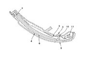
- the turn lamp assembly has an outer lens 5 (transparent member) on the front side (the side facing the outside when the turn lamp assembly is assembled to the vehicle door mirror) and a rear side (the turn lamp assembly is used as the vehicle door mirror).
- the base housing 3 (non-transparent member) on the side hidden from the outside in the assembled state constitutes an outer case (housing), and the inner housing 4 is incorporated into the inner space surrounded by the outer case.
- the inner housing 4 includes an inner member (non-transparent member) and a light guide member 6 (transparent member) incorporated into the inner member from the front, and is held by the base housing 3.
- a light source unit 8 having LEDs 9, 10, 11 is incorporated in the inner housing 4. Since the light guide member 6 is covered with the outer lens 5, stones or the like are prevented from hitting the light guide member 6 and being damaged, and raindrops are attached to the light guide member 6 to hinder the light guide function. Is prevented.
- the inner housing 4 that holds the light guide member 6 is incorporated in the base housing 3 and the outer lens 5 is covered, it is possible to assemble the turn lamp assembly (turn lamp assembly). Assembly efficiency) was poor.
- the present invention is intended to solve the problems in the prior art and to provide a turn lamp assembly with improved assemblability and a vehicle door mirror incorporating the turn lamp assembly.
- the turn lamp assembly of the present invention includes an outer shell having a structure in which a front transparent member and a back transparent member are overlapped with each other and joined to each other at a peripheral portion, and the back transparent member receives light emitted from a light source. It has an incident part, a light guide part that guides the incident light, and an emission part that emits the guided light. According to this, since the back side transparent member constituting the back side of the outer shell also serves as the light guide portion, the outer shell and the light guide portion are compared with the case where the portion constituting the back side of the outer shell and the light guide portion are configured by individual members. It is possible to reduce the number of parts of the members constituting the. Therefore, the assemblability of the turn lamp assembly can be improved.
- the turn lamp assembly of the present invention may have a light blocking surface on the back surface of the outer shell that blocks light transmitted through the back transparent member in the front and back direction. According to this, since the rear surface of the outer wall of the turn lamp assembly has a light-shielding surface, the turn lamp light is transmitted from the rear surface of the rear transparent member to the front side of the door mirror (rear side of the vehicle) while the turn lamp assembly is incorporated in the door mirror. It is possible to prevent the driver from seeing from the gap between the outer peripheral edge of the mirror plate and the opening of the mirror housing. Further, it is possible to prevent the interior of the door mirror from being seen through through the turn lamp assembly from the back side of the door mirror (vehicle front side).
- the outer shell has an elongated shape
- the back-side transparent member has a ridge extending in a longitudinal direction at a center portion in a short direction of the front surface, and the ridge is incident on the incident surface.
- the said light guide part is defined by the protrusion on the back side transparent member, whereby the light emitted from the light source can be efficiently guided to the emission part through the protrusion.
- the front transparent member may have a recess in which the protrusion enters the back surface. According to this, it is possible to suppress an increase in the thickness of the turn lamp assembly due to the presence of the protrusion by arranging the protrusion into the recess.
- the door mirror of the present invention is a vehicle door mirror incorporating a turn lamp assembly, wherein the turn lamp assembly includes an outer shell having a structure in which a front transparent member and a back transparent member are overlapped with each other and joined to each other at a peripheral portion,
- the back-side transparent member has an incident portion that receives light emitted from a light source, a light guide portion that guides the incident light, and an output portion that emits the guided light
- the vehicle door mirror includes: A light-shielding surface that shields light transmitted through the back-side transparent member in the front-back direction is provided on the back side of the outer shell of the turn lamp assembly.
- the turn lamp light leaks from the back side of the back side transparent member to the front side of the door mirror and the outer periphery of the mirror plate and the opening of the mirror housing It can be prevented from being visually recognized by a driver or the like through a gap between the two parts. Further, it is possible to prevent the inside of the door mirror from being seen through the turn lamp assembly from the back side of the door mirror.
- the light shielding surface is fixedly disposed on a rear surface of the outer surface of the turn lamp assembly or a surface facing the rear surface of the outer surface of the mirror housing in which the turn lamp assembly is disposed, or the rear surface of the outer surface and the rear surface of the outer surface. Between the mirror housing and the surface of the mirror housing. That is, the light shielding surface can be arranged at various positions.
- the light-shielding surface fixedly arranged on the surface of the mirror housing facing the back surface of the outer shell can be constituted by a material surface made of an opaque material that constitutes the mirror housing, for example. According to this, since the material surface of the mirror housing is used as it is as a light shielding surface, it is not necessary to prepare a separate member or to add a processing to configure the light shielding surface, and to easily arrange the light shielding surface. Can do.
- the door mirror according to the present invention depends on the material constituting the mirror housing when the turn lamp assembly is seen from the front surface side at any location from the rear surface of the outer wall of the turn lamp assembly to the light shielding surface. It may have a decorative surface that gives a visual effect different from the visual effect. According to this, the visual effect different from the visual effect by the material which comprises a mirror housing by a decorating surface can be given. The decorative surface can also serve as the light shielding surface.
- the decorative surface is fixedly disposed on, for example, the rear surface of the outer wall of the turn lamp assembly or the surface of the mirror housing facing the rear surface of the outer shell, or the mirror facing the rear surface of the outer shell and the rear surface of the outer shell. It can be arranged to be sandwiched between the housing surface. That is, the decorative surface can be arranged at various positions.
- the decorative surface is, for example, a plate-like or film-like decorative member attached to, or coated with, a metal film on the back surface of the outer wall of the turn lamp assembly or the surface of the mirror housing facing the back surface of the outer wall Film forming, embossing, embossing, and sandwiching a plate-like or film-like decorative member between the back surface of the outer shell and the surface of the mirror housing facing the back surface of the outer shell Can be.
- the decorative surface can be configured by various structures, whereby the decorative surface can increase the light emission efficiency of the turn lamp light to the front of the turn lamp assembly (front of the vehicle) or to the front of the turn lamp assembly. Design effects can be given.
- a lamp housing part having a concave shape and an opaque peripheral wall surface is formed in the mirror housing, and the turn lamp assembly is housed and disposed in the lamp housing part. According to this, the light emitted from the turn lamp assembly is prevented from leaking to the side of the turn lamp assembly and being visually recognized by the driver or the like.
- the transparent member on the back side has a substrate receiving part for holding the circuit board on which the light source is mounted, and the incident part holds the circuit board on the substrate receiving part. It can be arranged at the facing position. According to this, the light emitted from the light source can be reliably incident on the incident portion.
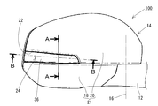
- FIG. 3 is a view showing an embodiment of the turn lamp assembly of the present invention, and is a cross-sectional view taken along the line BB of FIG. It is a rear view of the door mirror incorporating the turn lamp assembly of FIG.
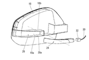
- FIG. 3 is an exploded perspective view showing a mirror housing body and a turn lamp assembly of the door mirror of FIG. 2.
- FIG. 2 is an exploded perspective view of the turn lamp assembly of FIG. 1.
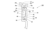
- FIG. 3 is a cross-sectional view taken along line AA in FIG. 2.
- FIG. 5 is a cross-sectional view showing a modification of the cross-sectional structure taken along the line AA in FIG. 2. It is sectional drawing of the longitudinal direction which shows the conventional turn lamp assembly described in patent document 1.
- FIG. 1 is a view showing an embodiment of the turn lamp assembly of the present invention, and is a cross-sectional view taken along the line BB of FIG. It is a rear view of the door mirror incorporating the turn lamp assembly of FIG.
- FIG. 3 is an exploded perspective
- FIG. 2 shows a rear view of a door mirror incorporating the turn lamp assembly of the present invention.
- the door mirror 100 is mounted on a mirror base 12 fixedly mounted on a right side door (not shown) of a vehicle, and a mirror rotating portion 14 is moved to a retracted position (non-use position) and a return position (use) with a rotating shaft 16 extending in the vertical direction. Position) and is rotatably supported so as to be displaceable.
- the mirror rotating unit 14 includes a mirror housing body (visor body) 18, a housing cover (visor cover) 20, a turn lamp assembly 24, a mirror surface angle adjusting mechanism (not shown), and a mirror plate (not shown). Have.
- the mirror housing body 18 is rotatably supported on the mirror base 12 by a rotation shaft 16 via a frame (not shown) (or directly without a frame).
- the housing cover 20 is mounted so as to cover the upper part on the back side of the mirror housing body 18.
- the turn lamp assembly 24 is attached to the mirror housing main body 18, and the light emitting display surface is exposed to the outside through an opening 22 that is formed horizontally at the boundary between the mirror housing main body 18 and the housing cover 20.
- the mirror surface angle adjusting mechanism is attached to the front surface of the frame or the front surface of the mirror housing body 18 in the front opening (not shown) of the mirror housing body 18.
- the mirror plate is mounted on the front surface of the mirror surface angle adjusting mechanism via a mirror holder or directly.
- the mirror housing body 18 and the housing cover 20 constitute a mirror housing 21.
- the mirror housing body 18 and the housing cover 20 are made of opaque resin.
- FIG. 3 shows the mirror housing body 18 and the turn lamp assembly 24 of the door mirror 100 in a state where they are separated from each other.
- a wall surface 18b is integrally formed on the rear surface of the mirror housing body 18, and thereby a concave lamp housing portion 28 is formed.
- the lamp accommodating portion 28 has a front shape that accommodates the turn lamp assembly 24 around the turn lamp assembly 24 with almost no gap.
- the surface 18 a of the mirror housing body 18 (the bottom surface of the lamp housing portion 28) facing the back surface of the turn lamp assembly 24 and the peripheral wall surface 28 a surrounding the turn lamp assembly 24 are closed without opening. Accordingly, the lamp housing portion 28 is configured to be light-shielding except for the front opening.
- the turn lamp assembly 24 in a state where the turn lamp assembly 24 is housed and disposed in the lamp housing portion 28, light emitted from the turn lamp assembly 24 leaks from the rear or side of the turn lamp assembly 24 and the front side of the mirror housing body 18 (rear side of the vehicle). Side) and being visually recognized by a driver or the like is prevented. Further, it is possible to prevent the inside of the housing main body 18 (inside the front opening of the mirror housing main body 18) from being seen through the turn lamp assembly 24 from the back side (vehicle front side) of the door mirror 100.
- the turn lamp assembly 24 is accommodated in the lamp accommodating portion 28 and fixedly attached to the mirror housing main body 18 with screws (not shown).
- a wiring 30 is led from the inside of the vehicle body into the mirror housing body 18 via the mirror base 12 (FIG. 2).
- a connector 32 is attached to the tip of the wiring 30.
- the connector 32 is connected to the end of the turn lamp assembly 24 on the side close to the vehicle body. As a result, lighting power is supplied to the light source in the turn lamp assembly 24 via the wiring 30.
- the housing cover 20 is mounted on the upper portion of the mirror housing body 18.
- FIG. 4 is an exploded view of the turn lamp assembly 24.
- the turn lamp assembly 24 includes a lamp housing (back side transparent member) 34 and an outer lens (front side transparent member) 36.
- the lamp housing 34 and the outer lens 36 are overlapped with each other, and are welded or bonded to each other around the peripheral edges 34a and 36a that are abutted with each other to join each other, thereby forming a space (cavity) 37 (FIG. 1) inside.
- An outer shell (housing) 38 is formed.
- the outer shape of the outer shell 38 is an elongated shape, and the planar shape (the shape when the outer shell 38 is viewed from above in a posture when mounted on a vehicle) is formed in a curved shape in accordance with the outer shape of the mirror housing 21 (FIG. 2).
- the longitudinal direction of the outer shell 38 is disposed in the horizontal direction, and the lateral direction is disposed in the vertical direction.
- the outer lens 36 is exposed to the outside of the door mirror 100 from the opening 22 (see FIG. 2), and the lamp housing 34 is disposed behind the outer lens 36.
- the lamp housing 34 is constituted by an integrally molded product made of a transparent resin member (for example, a colorless transparent resin member).
- the lamp housing 34 has a structure in which a peripheral edge portion 34a is formed in a flat plate shape around the entire circumference, and a protrusion 40 extending in the longitudinal direction is formed at the center portion in the short direction of the front surface.
- the outer lens 36 and the lamp housing 34 are joined to each other with the peripheral edge 36 a of the outer lens 36 abutted against the front surface of the flat peripheral edge 34 a of the lamp housing 34.
- a space (substrate receiving portion) 46 for accommodating and holding a circuit board 44 on which an LED (light source) 42 is mounted is formed at an end portion of the lamp housing 34 on the inner peripheral side close to the vehicle body.
- the outer lens 36 is constituted by an integrally molded product made of a transparent resin member (for example, a colorless transparent resin member).
- a recess 48 is formed on the back surface of the outer lens 36 in which the protrusion 40 of the lamp housing 34 enters in a non-contact manner across the cavity 37 (FIG. 1).
- FIG. 1 is a cross-sectional view of the turn lamp assembly 24 in the longitudinal direction (a cross-sectional view taken along the line BB in FIG. 2).
- the turn lamp assembly 24 is fixedly attached to the back surface of the mirror housing body 18.
- the end portion on the side close to the vehicle body in the longitudinal direction constitutes the incident portion 40a
- the end portion on the side away from the vehicle body constitutes the emission portion 40b
- the incidence portion 40a and the emission portion 40b constitutes a light guide lens part (light guide part) 40c.
- a connector connection port 35 is formed at the end of the lamp housing 34 on the side close to the vehicle body.
- a connector 32 (FIG.
- a circuit board 44 is accommodated and held in the board receiving portion 46 of the lamp housing 34.
- the terminal 44 a of the circuit board 44 protrudes from the connector connection port 35 to the outside of the turn lamp assembly 24.
- the light flux of the turn lamp light emitted from the LED 42 enters the ridge 40 from the incident portion 40a, is guided through the light guide lens portion 40c, and is emitted from the emission portion 40b to the outside of the ridge 40.
- the luminous flux of the turn lamp light emitted from the emission part 40b passes through the end part 36b of the outer lens 36 on the side far from the vehicle body, and is emitted toward the rear right side of the vehicle. Thereby, turn lamp light can be visually recognized from the other vehicle etc. which are drive
- part of the light flux of the turn lamp light incident from the incident portion 40a is emitted from the front surface of the lamp housing 34 at each position of the lamp housing 34, passes through the outer lens 36, and is emitted toward the front of the vehicle. Thereby, turn lamp light can be visually recognized also from the vehicle front.
- FIG. 5 is a cross-sectional view (a cross-sectional view taken along the line AA in FIG. 2) of the turn lamp assembly 24 in the short direction.
- the lamp housing 34 and the outer lens 36 are joined to each other directly and directly by welding or bonding (joint part 50) around the peripheral edges 34a and 36a that are abutted with each other to form an outer shell 38.
- a protrusion 40 is formed on the front surface of the lamp housing 34 at a position surrounded by the joint 50.
- a protrusion 40 enters the recess 48 on the back surface of the outer lens 36 through the cavity 37 in a non-contact manner.
- the turn lamp assembly 24 is fixedly mounted on the mirror housing body 18 by screwing in a state where the turn lamp assembly 24 is housed in the lamp housing portion 28 on the back surface of the mirror housing body 18.
- the housing cover 20 When the housing cover 20 is put on the mirror housing main body 18, only the top surface of the outer lens 36 is exposed to the outside from the opening 22 formed at the boundary between the mirror housing main body 18 and the housing cover 20.
- the part 50 and the lamp housing 34 are hidden from the outside by the mirror housing body 18 and the housing cover 20.
- the light shielding surface that shields light transmitted through the lamp housing 34 in the front and back direction is a surface 18a (the bottom surface of the lamp housing portion 28) of the mirror housing main body 18 made of an opaque resin material that faces the back surface of the turn lamp assembly 24. Composed.
- FIG. 6 shows a modification of the cross-sectional structure taken along the line AA in FIG.
- a decorative surface 52 is disposed between the opposing surfaces of the turn lamp assembly 24 and the mirror housing body 18.
- the decorative surface 52 it is possible to give a visual effect of showing colors, reflections, patterns and the like different from the background of the mirror housing main body 18. Thereby, the luminous efficiency of turn lamp light can be improved or a design effect can be given.
- the decorative surface 52 is, for example, -Fixedly arranged on the back surface 38a of the outer shell 38; A fixed arrangement on the surface 18a of the mirror housing body 18 facing the back surface 38a of the outer shell 38; -Sandwiched between the rear surface 38a of the outer shell 38 and the opposing surface 18a of the mirror housing body 18 (not fixed to either of the surfaces 18a, 38a), Etc. can be arranged.
- the decorative surface 52 is, for example, A plate-like or film-like decorative member is attached to the back surface 38a of the outer shell 38 or the opposing surface 18a of the mirror housing body 18.
- a paint having a color different from the color (material color) of the material of the facing surface 18a is applied to the back surface 38a of the outer shell 38 or the facing surface 18a of the mirror housing body 18.
- a metal film is formed (deposited) on the back surface 38a of the outer shell 38 or the facing surface 18a of the mirror housing body 18 by a film forming technique.
- a plate-like or film-like decorative member is sandwiched between the rear surface 38a of the outer shell 38 or the opposing surface 18a of the mirror housing body 18 (not fixed to either of the surfaces 18a, 38a. That is, the turn lamp assembly 24 is A plate-like or film-like decorative member is sandwiched by a force that is fixedly attached to the mirror housing body 18 with a screw), Or the like.
- the plate-shaped or film-shaped decorating member which comprises the decorating surface 52 is, for example, An opaque resin plate or opaque resin film having a ground color different from the material color of the facing surface 18a, A resin plate or resin film coated with a paint of a color different from the material color of the facing surface 18a, ⁇ A resin plate or resin film on which a metal film is formed by film formation technology, -Metal plate or metal foil-Resin plate or resin film with embossing or embossing Or the like.
- the decorative surface 52 when the decorative surface 52 is opaque, the decorative surface 52 also serves as a light shielding surface, and when the decorative surface 52 is transparent (the decorative surface 52 is a textured surface, an embossed surface, etc.
- the opposing surface 18a constitutes a light shielding surface.
- the concave lamp housing portion for housing the turn lamp assembly 24 is not formed on the back surface of the mirror housing main body 18, but the concave lamp housing portion 28 is formed as in FIGS. 3 and 5. You can also. In this way, the light emitted from the turn lamp assembly 24 leaks from the rear or side of the turn lamp assembly 24 and passes to the front side (rear side of the vehicle) of the mirror housing body 18 and is visually recognized by the driver or the like. Can be prevented. Further, it is possible to more reliably prevent the interior of the door mirror 100 from being seen through the turn lamp assembly 24 from the back side (the vehicle front side) of the door mirror 100.
- the surface 18 a of the mirror housing body 18 facing the back surface 38 a of the outer shell 38 is configured as a closed surface, but when the decorative surface 52 is opaque, the decorative surface 52 serves as a light shielding surface. Since it comprises, this surface 18a can also be comprised by the surface which has an opening part.
- both the front side transparent member and the back side transparent member of the present invention are configured to be colorless and transparent, and either one or both can be configured to be colored transparent or translucent (transparent with turbidity).
- SYMBOLS 18 ... Mirror housing main body, 18a The surface of the mirror housing (light-shielding surface) facing the back surface of an outer shell, 20 ... Housing cover, 21 ... Mirror housing, 24 ... Turn lamp assembly, 28 ... Lamp accommodating part, 28a ... Lamp accommodating 34 ... Lamp housing (back side transparent member), 34a ... Peripheral portion of lamp housing, 36 ... Outer lens (front side transparent member), 36a ... Peripheral portion of outer lens, 38 ... Outer shell, 38a ... Back surface of outer shell , 40 ... ridges, 40 a ... incident part, 40 b ... emitting part, 40 c ... light guide lens part (light guide part), 42 ... LED (light source), 44 ... circuit board, 46 ... board receiving part, 48 ... outer lens , 50 ... junction, 52 ... decorative surface, 100 ... vehicle door mirror
Landscapes
- Engineering & Computer Science (AREA)
- General Engineering & Computer Science (AREA)
- Mechanical Engineering (AREA)
- Multimedia (AREA)
- Physics & Mathematics (AREA)
- Microelectronics & Electronic Packaging (AREA)
- Optics & Photonics (AREA)
- Lighting Device Outwards From Vehicle And Optical Signal (AREA)
- Rear-View Mirror Devices That Are Mounted On The Exterior Of The Vehicle (AREA)
Abstract
Description
・外郭38の裏面38aに固定配置する、
・外郭38の裏面38aに対面するミラーハウジング本体18の面18aに固定配置する、
・外郭38の裏面38aとミラーハウジング本体18の対向面18aとの間に挟持して配置する(面18a,38aのいずれにも固定しない)、
等により配置することができる。
・外郭38の裏面38aまたはミラーハウジング本体18の対向面18aに対して板状またはフィルム状の加飾部材を貼着する、
・外郭38の裏面38aまたはミラーハウジング本体18の対向面18aに対して対向面18aの材料自体の色(素材色)とは異なる色の塗料を塗装する、
・外郭38の裏面38aまたはミラーハウジング本体18の対向面18aに対して成膜技術で金属膜を成膜(堆積)する、
・外郭38の裏面38aまたはミラーハウジング本体18の対向面18aに対してシボ加工またはエンボス加工を施す、
・外郭38の裏面38aまたはミラーハウジング本体18の対向面18aとの間に板状またはフィルム状の加飾部材を挟持する(面18a,38aのいずれにも固定しない。すなわち、ターンランプアセンブリ24をねじでミラーハウジング本体18に固定装着する力で板状またはフィルム状の加飾部材を挟み込む)、
等により構成することができる。
・対向面18aの素材色とは異なる地色を有する不透明樹脂板または不透明樹脂フィルム、
・対向面18aの素材色とは異なる色の塗料を塗装した樹脂板または樹脂フィルム、
・成膜技術で金属膜を成膜した樹脂板または樹脂フィルム、
・金属板または金属箔
・シボ加工またはエンボス加工を施した樹脂板または樹脂フィルム、
等で構成することができる。図6の構成では、加飾面52が不透明である場合は加飾面52が遮光面を兼ね、加飾面52が透明である場合(加飾面52がシボ加工面、エンボス加工面等である場合)は、対向面18aが遮光面を構成することになる。
Claims (18)
- ターンランプアセンブリを組み込んだ車両用ドアミラーにおいて、
前記ターンランプアセンブリは表側透明部材と裏側透明部材を互いに重ね合わせて周縁部で相互に接合した構造を有する外郭を有し、
前記裏側透明部材は光源から発せられた光を入射する入射部と、該入射した光を導光する導光部と、該導光された光を出射する出射部を有し、
前記車両用ドアミラーは前記ターンランプアセンブリの前記外郭の裏面側に、前記裏側透明部材を表裏方向に透過する光を遮光する遮光面を有する
車両用ドアミラー。 - 前記ターンランプアセンブリの前記外郭が細長形状を有し、
前記裏側透明部材がその前面の短手方向の中央部に長手方向に延在する突条を有し、
前記突条が前記入射部と、前記導光部と、前記出射部を有する
請求項1に記載の車両用ドアミラー。 - 前記遮光面が、前記ターンランプアセンブリの前記外郭の裏面もしくは該ターンランプアセンブリを配置したミラーハウジングの該外郭の裏面に対面する面に固定配置され、または前記外郭の裏面と該外郭の裏面に対面する前記ミラーハウジングの面との間に挟持して配置されている請求項1に記載の車両用ドアミラー。
- 前記遮光面が、前記ターンランプアセンブリの前記外郭の裏面もしくは該ターンランプアセンブリを配置したミラーハウジングの該外郭の裏面に対面する面に固定配置され、または前記外郭の裏面と該外郭の裏面に対面する前記ミラーハウジングの面との間に挟持して配置されている請求項2に記載の車両用ドアミラー。
- 前記外郭の裏面に対面する前記ミラーハウジングの面に固定配置される前記遮光面が、前記ミラーハウジングを構成する不透明材料による素材面で構成される請求項3に記載の車両用ドアミラー。
- 前記ターンランプアセンブリの前記外郭の裏面から前記遮光面に至るいずれかの箇所に、該ターンランプアセンブリを前面側から透過して見たときに、ミラーハウジングを構成する材料による視覚的効果とは異なる視覚的効果を与える加飾面を有する請求項1に記載の車両用ドアミラー。
- 前記ターンランプアセンブリの前記外郭の裏面から前記遮光面に至るいずれかの箇所に、該ターンランプアセンブリを前面側から透過して見たときに、ミラーハウジングを構成する材料による視覚的効果とは異なる視覚的効果を与える加飾面を有する請求項2に記載の車両用ドアミラー。
- 前記ターンランプアセンブリの前記外郭の裏面から前記遮光面に至るいずれかの箇所に、該ターンランプアセンブリを前面側から透過して見たときに、ミラーハウジングを構成する材料による視覚的効果とは異なる視覚的効果を与える加飾面を有する請求項3に記載の車両用ドアミラー。
- 前記ターンランプアセンブリの前記外郭の裏面から前記遮光面に至るいずれかの箇所に、該ターンランプアセンブリを前面側から透過して見たときに、ミラーハウジングを構成する材料による視覚的効果とは異なる視覚的効果を与える加飾面を有する請求項5に記載の車両用ドアミラー。
- 前記加飾面が、前記ターンランプアセンブリの前記外郭の裏面もしくは該外郭の裏面に対面する前記ミラーハウジングの面に固定配置され、または前記外郭の裏面と該外郭の裏面に対面する前記ミラーハウジングの面との間に挟持して配置されている請求項6に記載の車両用ドアミラー。
- 前記加飾面が、前記ターンランプアセンブリの前記外郭の裏面もしくは該外郭の裏面に対面する前記ミラーハウジングの面に対する板状またはフィルム状の加飾部材の貼着、塗装、金属膜の成膜、シボ加工、エンボス加工、前記外郭の裏面と該外郭の裏面に対面する前記ミラーハウジングの面との間への板状またはフィルム状の加飾部材の挟持のいずれかにより配置されている請求項10に記載の車両用ドアミラー。
- 前記加飾面が前記遮光面を兼ねる請求項6に記載の車両用ドアミラー。
- ミラーハウジングに凹状で周壁面が不透明のランプ収容部が形成され、
前記ターンランプアセンブリが前記ランプ収容部に収容配置されている請求項1に記載の車両用ドアミラー。 - 前記裏側透明部材が、前記光源を搭載した回路基板を保持する基板受部を有し、
前記入射部が、前記基板受部に前記回路基板を保持した状態で前記光源と対面する位置に配置されている請求項1に記載の車両用ドアミラー。 - 車両用ドアミラーに組み込まれるターンランプアセンブリにおいて、
前記ターンランプアセンブリが、表側透明部材と裏側透明部材を互いに重ね合わせて周縁部で相互に接合した構造を有する外郭を有し、
前記裏側透明部材が、光源から発せられた光を入射する入射部と、該入射した光を導光する導光部と、該導光された光を出射する出射部を有する
ターンランプアセンブリ。 - 前記外郭の裏面に、前記裏側透明部材を表裏方向に透過する光を遮光する遮光面を有する請求項15に記載のターンランプアセンブリ。
- 前記外郭が細長形状を有し、
前記裏側透明部材がその前面の短手方向の中央部に長手方向に延在する突条を有し、
前記突条が前記入射部と、前記導光部と、前記出射部を有する
請求項15に記載のターンランプアセンブリ。 - 前記外郭が細長形状を有し、
前記裏側透明部材がその前面の短手方向の中央部に長手方向に延在する突条を有し、
前記突条が前記入射部と、前記導光部と、前記出射部を有する
請求項16に記載のターンランプアセンブリ。
Priority Applications (2)
| Application Number | Priority Date | Filing Date | Title |
|---|---|---|---|
| CN201480033969.7A CN105283354B (zh) | 2013-06-14 | 2014-06-04 | 车辆用车门后视镜的转向灯组件及车辆用车门后视镜 |
| US14/897,318 US9688203B2 (en) | 2013-06-14 | 2014-06-04 | Turn signal lamp assembly for vehicle door mirror, and vehicle door mirror |
Applications Claiming Priority (2)
| Application Number | Priority Date | Filing Date | Title |
|---|---|---|---|
| JP2013-125155 | 2013-06-14 | ||
| JP2013125155A JP6184186B2 (ja) | 2013-06-14 | 2013-06-14 | 車両用ドアミラーのターンランプアセンブリおよび車両用ドアミラー |
Publications (1)
| Publication Number | Publication Date |
|---|---|
| WO2014199875A1 true WO2014199875A1 (ja) | 2014-12-18 |
Family
ID=52022172
Family Applications (1)
| Application Number | Title | Priority Date | Filing Date |
|---|---|---|---|
| PCT/JP2014/064818 Ceased WO2014199875A1 (ja) | 2013-06-14 | 2014-06-04 | 車両用ドアミラーのターンランプアセンブリおよび車両用ドアミラー |
Country Status (4)
| Country | Link |
|---|---|
| US (1) | US9688203B2 (ja) |
| JP (1) | JP6184186B2 (ja) |
| CN (1) | CN105283354B (ja) |
| WO (1) | WO2014199875A1 (ja) |
Cited By (1)
| Publication number | Priority date | Publication date | Assignee | Title |
|---|---|---|---|---|
| JP2017171137A (ja) * | 2016-03-24 | 2017-09-28 | ソニー株式会社 | 撮像部支持装置 |
Families Citing this family (7)
| Publication number | Priority date | Publication date | Assignee | Title |
|---|---|---|---|---|
| CN105972542B (zh) * | 2016-07-20 | 2018-07-03 | 宁波福尔达智能科技有限公司 | 汽车转向灯 |
| DE102016125215A1 (de) * | 2016-12-21 | 2018-06-21 | HELLA GmbH & Co. KGaA | Beleuchtungsvorrichtung für Fahrzeuge |
| JP7282666B2 (ja) * | 2019-12-23 | 2023-05-29 | 株式会社ミツバ | 射出成形体 |
| CN115023370B (zh) * | 2020-01-23 | 2025-12-19 | Lg伊诺特有限公司 | 光学组件和具有该光学组件的后视镜组件 |
| CN115342311B (zh) * | 2020-04-07 | 2026-03-27 | 武汉路特斯汽车有限公司 | 一种车辆外饰投射灯光秀的结构及控制方法 |
| DE102022128895B4 (de) * | 2022-11-01 | 2025-09-18 | Motherson Innovations Company Limited | Beleuchtungsvorrichtung mit zwei lichtquellen und zwei lichtleitern für eine rückblickvorrichtung eines fahrzeugs, rückblickvorrichtung mit dieser beleuchtungsvorrichtung und fahrzeug mit dieser beleuchtungsvorrichtung |
| US12135116B1 (en) | 2024-02-22 | 2024-11-05 | Motherson Innovations Company Limited | Multi-functional light module for an exterior mirror |
Citations (4)
| Publication number | Priority date | Publication date | Assignee | Title |
|---|---|---|---|---|
| JP2007280924A (ja) * | 2006-03-16 | 2007-10-25 | Ichikoh Ind Ltd | 導光レンズ及び導光レンズの製造方法 |
| JP2008226755A (ja) * | 2007-03-15 | 2008-09-25 | Mitsuba Corp | 車両用ランプ |
| JP2009099458A (ja) * | 2007-10-18 | 2009-05-07 | Mitsuba Corp | 車両用ランプ |
| JP2013075608A (ja) * | 2011-09-30 | 2013-04-25 | Koito Mfg Co Ltd | 車両用灯具 |
Family Cites Families (9)
| Publication number | Priority date | Publication date | Assignee | Title |
|---|---|---|---|---|
| JP4413764B2 (ja) * | 2004-12-10 | 2010-02-10 | 株式会社小糸製作所 | 車両用灯具 |
| TWM310827U (en) * | 2006-11-03 | 2007-05-01 | Ken Sean Factory Co Ltd | Car indicator light with light-conducting function |
| JP5147355B2 (ja) | 2007-10-18 | 2013-02-20 | 株式会社ミツバ | 車両用ランプ |
| JP5075572B2 (ja) * | 2007-10-18 | 2012-11-21 | 株式会社ミツバ | ドアミラー |
| JP5238411B2 (ja) * | 2008-08-28 | 2013-07-17 | 株式会社小糸製作所 | 車両用灯具 |
| JP5425443B2 (ja) * | 2008-10-31 | 2014-02-26 | 株式会社ミツバ | 車両用ランプ |
| EP2399780B1 (de) * | 2010-06-28 | 2013-07-31 | SMR Patents S.à.r.l. | Außenrückblickspiegel |
| JP2013014313A (ja) | 2011-06-07 | 2013-01-24 | Murakami Corp | ターンランプユニット |
| CN202656923U (zh) * | 2012-07-11 | 2013-01-09 | 麦格纳(太仓)汽车科技有限公司 | 双向导光式汽车侧转向灯 |
-
2013
- 2013-06-14 JP JP2013125155A patent/JP6184186B2/ja active Active
-
2014
- 2014-06-04 WO PCT/JP2014/064818 patent/WO2014199875A1/ja not_active Ceased
- 2014-06-04 US US14/897,318 patent/US9688203B2/en active Active
- 2014-06-04 CN CN201480033969.7A patent/CN105283354B/zh active Active
Patent Citations (4)
| Publication number | Priority date | Publication date | Assignee | Title |
|---|---|---|---|---|
| JP2007280924A (ja) * | 2006-03-16 | 2007-10-25 | Ichikoh Ind Ltd | 導光レンズ及び導光レンズの製造方法 |
| JP2008226755A (ja) * | 2007-03-15 | 2008-09-25 | Mitsuba Corp | 車両用ランプ |
| JP2009099458A (ja) * | 2007-10-18 | 2009-05-07 | Mitsuba Corp | 車両用ランプ |
| JP2013075608A (ja) * | 2011-09-30 | 2013-04-25 | Koito Mfg Co Ltd | 車両用灯具 |
Cited By (2)
| Publication number | Priority date | Publication date | Assignee | Title |
|---|---|---|---|---|
| JP2017171137A (ja) * | 2016-03-24 | 2017-09-28 | ソニー株式会社 | 撮像部支持装置 |
| US10682965B2 (en) | 2016-03-24 | 2020-06-16 | Sony Corporation | Imaging unit support apparatus |
Also Published As
| Publication number | Publication date |
|---|---|
| JP2015000614A (ja) | 2015-01-05 |
| US9688203B2 (en) | 2017-06-27 |
| JP6184186B2 (ja) | 2017-08-23 |
| CN105283354B (zh) | 2017-09-22 |
| CN105283354A (zh) | 2016-01-27 |
| US20160129843A1 (en) | 2016-05-12 |
Similar Documents
| Publication | Publication Date | Title |
|---|---|---|
| JP6184186B2 (ja) | 車両用ドアミラーのターンランプアセンブリおよび車両用ドアミラー | |
| JP6607146B2 (ja) | 発光エンブレム | |
| US9050937B2 (en) | Logo device for vehicle | |
| JP7043001B2 (ja) | ミリ波レーダーユニット | |
| US9541703B2 (en) | Lamp | |
| JP6199144B2 (ja) | 照明装置 | |
| JP5005109B1 (ja) | 車両用led発光エンブレム | |
| JP6081784B2 (ja) | 発光装置 | |
| CN112622753A (zh) | 车窗和汽车 | |
| US9227557B2 (en) | Vehicle rearview mirror with indicator function | |
| JP6311884B2 (ja) | 照明装置 | |
| WO2022118893A1 (ja) | 車両用サンバイザ | |
| JP6674143B2 (ja) | 装飾部品 | |
| JP6769135B2 (ja) | 車両用灯具、車両用灯具を備える車両用後方視認装置 | |
| JP2015065113A (ja) | 照明装置 | |
| JP7102279B2 (ja) | 採光建築材 | |
| JP4733064B2 (ja) | 車両用ランプ | |
| CN117957400A (zh) | 车辆用灯具 | |
| CN107388097B (zh) | 一种led灯的导光结构和一种机器人眼睛 | |
| JP6987523B2 (ja) | 車両用灯具 | |
| JP2019200937A (ja) | 車両用灯具 | |
| JP2013103701A (ja) | 車両用エンブレム | |
| JP5633441B2 (ja) | 車両用照明装置 | |
| JP2005301157A (ja) | 面状発光体 | |
| JP6762756B2 (ja) | 乗物用内装材 |
Legal Events
| Date | Code | Title | Description |
|---|---|---|---|
| WWE | Wipo information: entry into national phase |
Ref document number: 201480033969.7 Country of ref document: CN |
|
| 121 | Ep: the epo has been informed by wipo that ep was designated in this application |
Ref document number: 14810996 Country of ref document: EP Kind code of ref document: A1 |
|
| WWE | Wipo information: entry into national phase |
Ref document number: 14897318 Country of ref document: US |
|
| NENP | Non-entry into the national phase |
Ref country code: DE |
|
| 122 | Ep: pct application non-entry in european phase |
Ref document number: 14810996 Country of ref document: EP Kind code of ref document: A1 |