WO2014196506A1 - Dispositif et procédé de commande de charge - Google Patents
Dispositif et procédé de commande de charge Download PDFInfo
- Publication number
- WO2014196506A1 WO2014196506A1 PCT/JP2014/064656 JP2014064656W WO2014196506A1 WO 2014196506 A1 WO2014196506 A1 WO 2014196506A1 JP 2014064656 W JP2014064656 W JP 2014064656W WO 2014196506 A1 WO2014196506 A1 WO 2014196506A1
- Authority
- WO
- WIPO (PCT)
- Prior art keywords
- secondary battery
- voltage
- vehicle
- alternator
- state
- Prior art date
Links
- 238000000034 method Methods 0.000 title claims description 65
- 230000001172 regenerating effect Effects 0.000 claims abstract description 24
- 238000001514 detection method Methods 0.000 claims abstract description 19
- 239000000446 fuel Substances 0.000 claims description 28
- 230000007423 decrease Effects 0.000 claims description 12
- 230000008859 change Effects 0.000 claims description 7
- 239000003990 capacitor Substances 0.000 claims description 6
- 238000003487 electrochemical reaction Methods 0.000 claims description 2
- 238000001179 sorption measurement Methods 0.000 claims description 2
- 230000008569 process Effects 0.000 description 47
- 238000010248 power generation Methods 0.000 description 19
- 238000012545 processing Methods 0.000 description 11
- 230000008929 regeneration Effects 0.000 description 10
- 238000011069 regeneration method Methods 0.000 description 10
- 238000010586 diagram Methods 0.000 description 9
- 239000007858 starting material Substances 0.000 description 5
- 230000006866 deterioration Effects 0.000 description 4
- OKTJSMMVPCPJKN-UHFFFAOYSA-N Carbon Chemical compound [C] OKTJSMMVPCPJKN-UHFFFAOYSA-N 0.000 description 3
- PXHVJJICTQNCMI-UHFFFAOYSA-N Nickel Chemical compound [Ni] PXHVJJICTQNCMI-UHFFFAOYSA-N 0.000 description 3
- 239000004065 semiconductor Substances 0.000 description 3
- 230000009466 transformation Effects 0.000 description 3
- 230000001133 acceleration Effects 0.000 description 2
- 244000145845 chattering Species 0.000 description 2
- 230000003247 decreasing effect Effects 0.000 description 2
- 238000007599 discharging Methods 0.000 description 2
- 230000006870 function Effects 0.000 description 2
- 238000012423 maintenance Methods 0.000 description 2
- 238000005259 measurement Methods 0.000 description 2
- 229910052759 nickel Inorganic materials 0.000 description 2
- 230000000630 rising effect Effects 0.000 description 2
- WHXSMMKQMYFTQS-UHFFFAOYSA-N Lithium Chemical compound [Li] WHXSMMKQMYFTQS-UHFFFAOYSA-N 0.000 description 1
- 238000009825 accumulation Methods 0.000 description 1
- 230000003044 adaptive effect Effects 0.000 description 1
- 230000032683 aging Effects 0.000 description 1
- 239000011230 binding agent Substances 0.000 description 1
- 230000005540 biological transmission Effects 0.000 description 1
- 229910052799 carbon Inorganic materials 0.000 description 1
- 239000003575 carbonaceous material Substances 0.000 description 1
- 239000011247 coating layer Substances 0.000 description 1
- 238000004891 communication Methods 0.000 description 1
- 239000002131 composite material Substances 0.000 description 1
- 230000000694 effects Effects 0.000 description 1
- 230000007613 environmental effect Effects 0.000 description 1
- 238000011156 evaluation Methods 0.000 description 1
- 230000005284 excitation Effects 0.000 description 1
- 230000012447 hatching Effects 0.000 description 1
- 229910052744 lithium Inorganic materials 0.000 description 1
- 238000004519 manufacturing process Methods 0.000 description 1
- 229910052987 metal hydride Inorganic materials 0.000 description 1
- 239000000203 mixture Substances 0.000 description 1
- 239000007773 negative electrode material Substances 0.000 description 1
- -1 nickel metal hydride Chemical class 0.000 description 1
- 230000001141 propulsive effect Effects 0.000 description 1
- 230000019635 sulfation Effects 0.000 description 1
- 238000005670 sulfation reaction Methods 0.000 description 1
- 230000007704 transition Effects 0.000 description 1
Images


Classifications
-
- B—PERFORMING OPERATIONS; TRANSPORTING
- B60—VEHICLES IN GENERAL
- B60L—PROPULSION OF ELECTRICALLY-PROPELLED VEHICLES; SUPPLYING ELECTRIC POWER FOR AUXILIARY EQUIPMENT OF ELECTRICALLY-PROPELLED VEHICLES; ELECTRODYNAMIC BRAKE SYSTEMS FOR VEHICLES IN GENERAL; MAGNETIC SUSPENSION OR LEVITATION FOR VEHICLES; MONITORING OPERATING VARIABLES OF ELECTRICALLY-PROPELLED VEHICLES; ELECTRIC SAFETY DEVICES FOR ELECTRICALLY-PROPELLED VEHICLES
- B60L1/00—Supplying electric power to auxiliary equipment of vehicles
- B60L1/003—Supplying electric power to auxiliary equipment of vehicles to auxiliary motors, e.g. for pumps, compressors
-
- B—PERFORMING OPERATIONS; TRANSPORTING
- B60—VEHICLES IN GENERAL
- B60L—PROPULSION OF ELECTRICALLY-PROPELLED VEHICLES; SUPPLYING ELECTRIC POWER FOR AUXILIARY EQUIPMENT OF ELECTRICALLY-PROPELLED VEHICLES; ELECTRODYNAMIC BRAKE SYSTEMS FOR VEHICLES IN GENERAL; MAGNETIC SUSPENSION OR LEVITATION FOR VEHICLES; MONITORING OPERATING VARIABLES OF ELECTRICALLY-PROPELLED VEHICLES; ELECTRIC SAFETY DEVICES FOR ELECTRICALLY-PROPELLED VEHICLES
- B60L15/00—Methods, circuits, or devices for controlling the traction-motor speed of electrically-propelled vehicles
- B60L15/20—Methods, circuits, or devices for controlling the traction-motor speed of electrically-propelled vehicles for control of the vehicle or its driving motor to achieve a desired performance, e.g. speed, torque, programmed variation of speed
-
- B—PERFORMING OPERATIONS; TRANSPORTING
- B60—VEHICLES IN GENERAL
- B60L—PROPULSION OF ELECTRICALLY-PROPELLED VEHICLES; SUPPLYING ELECTRIC POWER FOR AUXILIARY EQUIPMENT OF ELECTRICALLY-PROPELLED VEHICLES; ELECTRODYNAMIC BRAKE SYSTEMS FOR VEHICLES IN GENERAL; MAGNETIC SUSPENSION OR LEVITATION FOR VEHICLES; MONITORING OPERATING VARIABLES OF ELECTRICALLY-PROPELLED VEHICLES; ELECTRIC SAFETY DEVICES FOR ELECTRICALLY-PROPELLED VEHICLES
- B60L50/00—Electric propulsion with power supplied within the vehicle
- B60L50/10—Electric propulsion with power supplied within the vehicle using propulsion power supplied by engine-driven generators, e.g. generators driven by combustion engines
- B60L50/16—Electric propulsion with power supplied within the vehicle using propulsion power supplied by engine-driven generators, e.g. generators driven by combustion engines with provision for separate direct mechanical propulsion
-
- B—PERFORMING OPERATIONS; TRANSPORTING
- B60—VEHICLES IN GENERAL
- B60L—PROPULSION OF ELECTRICALLY-PROPELLED VEHICLES; SUPPLYING ELECTRIC POWER FOR AUXILIARY EQUIPMENT OF ELECTRICALLY-PROPELLED VEHICLES; ELECTRODYNAMIC BRAKE SYSTEMS FOR VEHICLES IN GENERAL; MAGNETIC SUSPENSION OR LEVITATION FOR VEHICLES; MONITORING OPERATING VARIABLES OF ELECTRICALLY-PROPELLED VEHICLES; ELECTRIC SAFETY DEVICES FOR ELECTRICALLY-PROPELLED VEHICLES
- B60L50/00—Electric propulsion with power supplied within the vehicle
- B60L50/40—Electric propulsion with power supplied within the vehicle using propulsion power supplied by capacitors
-
- B—PERFORMING OPERATIONS; TRANSPORTING
- B60—VEHICLES IN GENERAL
- B60L—PROPULSION OF ELECTRICALLY-PROPELLED VEHICLES; SUPPLYING ELECTRIC POWER FOR AUXILIARY EQUIPMENT OF ELECTRICALLY-PROPELLED VEHICLES; ELECTRODYNAMIC BRAKE SYSTEMS FOR VEHICLES IN GENERAL; MAGNETIC SUSPENSION OR LEVITATION FOR VEHICLES; MONITORING OPERATING VARIABLES OF ELECTRICALLY-PROPELLED VEHICLES; ELECTRIC SAFETY DEVICES FOR ELECTRICALLY-PROPELLED VEHICLES
- B60L53/00—Methods of charging batteries, specially adapted for electric vehicles; Charging stations or on-board charging equipment therefor; Exchange of energy storage elements in electric vehicles
- B60L53/60—Monitoring or controlling charging stations
- B60L53/66—Data transfer between charging stations and vehicles
- B60L53/665—Methods related to measuring, billing or payment
-
- B—PERFORMING OPERATIONS; TRANSPORTING
- B60—VEHICLES IN GENERAL
- B60L—PROPULSION OF ELECTRICALLY-PROPELLED VEHICLES; SUPPLYING ELECTRIC POWER FOR AUXILIARY EQUIPMENT OF ELECTRICALLY-PROPELLED VEHICLES; ELECTRODYNAMIC BRAKE SYSTEMS FOR VEHICLES IN GENERAL; MAGNETIC SUSPENSION OR LEVITATION FOR VEHICLES; MONITORING OPERATING VARIABLES OF ELECTRICALLY-PROPELLED VEHICLES; ELECTRIC SAFETY DEVICES FOR ELECTRICALLY-PROPELLED VEHICLES
- B60L58/00—Methods or circuit arrangements for monitoring or controlling batteries or fuel cells, specially adapted for electric vehicles
- B60L58/10—Methods or circuit arrangements for monitoring or controlling batteries or fuel cells, specially adapted for electric vehicles for monitoring or controlling batteries
- B60L58/12—Methods or circuit arrangements for monitoring or controlling batteries or fuel cells, specially adapted for electric vehicles for monitoring or controlling batteries responding to state of charge [SoC]
-
- B—PERFORMING OPERATIONS; TRANSPORTING
- B60—VEHICLES IN GENERAL
- B60L—PROPULSION OF ELECTRICALLY-PROPELLED VEHICLES; SUPPLYING ELECTRIC POWER FOR AUXILIARY EQUIPMENT OF ELECTRICALLY-PROPELLED VEHICLES; ELECTRODYNAMIC BRAKE SYSTEMS FOR VEHICLES IN GENERAL; MAGNETIC SUSPENSION OR LEVITATION FOR VEHICLES; MONITORING OPERATING VARIABLES OF ELECTRICALLY-PROPELLED VEHICLES; ELECTRIC SAFETY DEVICES FOR ELECTRICALLY-PROPELLED VEHICLES
- B60L7/00—Electrodynamic brake systems for vehicles in general
- B60L7/10—Dynamic electric regenerative braking
- B60L7/18—Controlling the braking effect
-
- B—PERFORMING OPERATIONS; TRANSPORTING
- B60—VEHICLES IN GENERAL
- B60W—CONJOINT CONTROL OF VEHICLE SUB-UNITS OF DIFFERENT TYPE OR DIFFERENT FUNCTION; CONTROL SYSTEMS SPECIALLY ADAPTED FOR HYBRID VEHICLES; ROAD VEHICLE DRIVE CONTROL SYSTEMS FOR PURPOSES NOT RELATED TO THE CONTROL OF A PARTICULAR SUB-UNIT
- B60W10/00—Conjoint control of vehicle sub-units of different type or different function
- B60W10/04—Conjoint control of vehicle sub-units of different type or different function including control of propulsion units
- B60W10/08—Conjoint control of vehicle sub-units of different type or different function including control of propulsion units including control of electric propulsion units, e.g. motors or generators
-
- B—PERFORMING OPERATIONS; TRANSPORTING
- B60—VEHICLES IN GENERAL
- B60W—CONJOINT CONTROL OF VEHICLE SUB-UNITS OF DIFFERENT TYPE OR DIFFERENT FUNCTION; CONTROL SYSTEMS SPECIALLY ADAPTED FOR HYBRID VEHICLES; ROAD VEHICLE DRIVE CONTROL SYSTEMS FOR PURPOSES NOT RELATED TO THE CONTROL OF A PARTICULAR SUB-UNIT
- B60W10/00—Conjoint control of vehicle sub-units of different type or different function
- B60W10/24—Conjoint control of vehicle sub-units of different type or different function including control of energy storage means
- B60W10/26—Conjoint control of vehicle sub-units of different type or different function including control of energy storage means for electrical energy, e.g. batteries or capacitors
-
- B—PERFORMING OPERATIONS; TRANSPORTING
- B60—VEHICLES IN GENERAL
- B60W—CONJOINT CONTROL OF VEHICLE SUB-UNITS OF DIFFERENT TYPE OR DIFFERENT FUNCTION; CONTROL SYSTEMS SPECIALLY ADAPTED FOR HYBRID VEHICLES; ROAD VEHICLE DRIVE CONTROL SYSTEMS FOR PURPOSES NOT RELATED TO THE CONTROL OF A PARTICULAR SUB-UNIT
- B60W20/00—Control systems specially adapted for hybrid vehicles
- B60W20/10—Controlling the power contribution of each of the prime movers to meet required power demand
- B60W20/13—Controlling the power contribution of each of the prime movers to meet required power demand in order to stay within battery power input or output limits; in order to prevent overcharging or battery depletion
- B60W20/14—Controlling the power contribution of each of the prime movers to meet required power demand in order to stay within battery power input or output limits; in order to prevent overcharging or battery depletion in conjunction with braking regeneration
-
- B—PERFORMING OPERATIONS; TRANSPORTING
- B60—VEHICLES IN GENERAL
- B60W—CONJOINT CONTROL OF VEHICLE SUB-UNITS OF DIFFERENT TYPE OR DIFFERENT FUNCTION; CONTROL SYSTEMS SPECIALLY ADAPTED FOR HYBRID VEHICLES; ROAD VEHICLE DRIVE CONTROL SYSTEMS FOR PURPOSES NOT RELATED TO THE CONTROL OF A PARTICULAR SUB-UNIT
- B60W30/00—Purposes of road vehicle drive control systems not related to the control of a particular sub-unit, e.g. of systems using conjoint control of vehicle sub-units
- B60W30/18—Propelling the vehicle
- B60W30/18009—Propelling the vehicle related to particular drive situations
- B60W30/18109—Braking
- B60W30/18127—Regenerative braking
-
- H—ELECTRICITY
- H01—ELECTRIC ELEMENTS
- H01M—PROCESSES OR MEANS, e.g. BATTERIES, FOR THE DIRECT CONVERSION OF CHEMICAL ENERGY INTO ELECTRICAL ENERGY
- H01M10/00—Secondary cells; Manufacture thereof
- H01M10/42—Methods or arrangements for servicing or maintenance of secondary cells or secondary half-cells
- H01M10/44—Methods for charging or discharging
-
- B—PERFORMING OPERATIONS; TRANSPORTING
- B60—VEHICLES IN GENERAL
- B60L—PROPULSION OF ELECTRICALLY-PROPELLED VEHICLES; SUPPLYING ELECTRIC POWER FOR AUXILIARY EQUIPMENT OF ELECTRICALLY-PROPELLED VEHICLES; ELECTRODYNAMIC BRAKE SYSTEMS FOR VEHICLES IN GENERAL; MAGNETIC SUSPENSION OR LEVITATION FOR VEHICLES; MONITORING OPERATING VARIABLES OF ELECTRICALLY-PROPELLED VEHICLES; ELECTRIC SAFETY DEVICES FOR ELECTRICALLY-PROPELLED VEHICLES
- B60L2210/00—Converter types
- B60L2210/10—DC to DC converters
-
- B—PERFORMING OPERATIONS; TRANSPORTING
- B60—VEHICLES IN GENERAL
- B60L—PROPULSION OF ELECTRICALLY-PROPELLED VEHICLES; SUPPLYING ELECTRIC POWER FOR AUXILIARY EQUIPMENT OF ELECTRICALLY-PROPELLED VEHICLES; ELECTRODYNAMIC BRAKE SYSTEMS FOR VEHICLES IN GENERAL; MAGNETIC SUSPENSION OR LEVITATION FOR VEHICLES; MONITORING OPERATING VARIABLES OF ELECTRICALLY-PROPELLED VEHICLES; ELECTRIC SAFETY DEVICES FOR ELECTRICALLY-PROPELLED VEHICLES
- B60L2210/00—Converter types
- B60L2210/30—AC to DC converters
-
- B—PERFORMING OPERATIONS; TRANSPORTING
- B60—VEHICLES IN GENERAL
- B60L—PROPULSION OF ELECTRICALLY-PROPELLED VEHICLES; SUPPLYING ELECTRIC POWER FOR AUXILIARY EQUIPMENT OF ELECTRICALLY-PROPELLED VEHICLES; ELECTRODYNAMIC BRAKE SYSTEMS FOR VEHICLES IN GENERAL; MAGNETIC SUSPENSION OR LEVITATION FOR VEHICLES; MONITORING OPERATING VARIABLES OF ELECTRICALLY-PROPELLED VEHICLES; ELECTRIC SAFETY DEVICES FOR ELECTRICALLY-PROPELLED VEHICLES
- B60L2210/00—Converter types
- B60L2210/40—DC to AC converters
-
- B—PERFORMING OPERATIONS; TRANSPORTING
- B60—VEHICLES IN GENERAL
- B60L—PROPULSION OF ELECTRICALLY-PROPELLED VEHICLES; SUPPLYING ELECTRIC POWER FOR AUXILIARY EQUIPMENT OF ELECTRICALLY-PROPELLED VEHICLES; ELECTRODYNAMIC BRAKE SYSTEMS FOR VEHICLES IN GENERAL; MAGNETIC SUSPENSION OR LEVITATION FOR VEHICLES; MONITORING OPERATING VARIABLES OF ELECTRICALLY-PROPELLED VEHICLES; ELECTRIC SAFETY DEVICES FOR ELECTRICALLY-PROPELLED VEHICLES
- B60L2240/00—Control parameters of input or output; Target parameters
- B60L2240/10—Vehicle control parameters
- B60L2240/12—Speed
-
- B—PERFORMING OPERATIONS; TRANSPORTING
- B60—VEHICLES IN GENERAL
- B60L—PROPULSION OF ELECTRICALLY-PROPELLED VEHICLES; SUPPLYING ELECTRIC POWER FOR AUXILIARY EQUIPMENT OF ELECTRICALLY-PROPELLED VEHICLES; ELECTRODYNAMIC BRAKE SYSTEMS FOR VEHICLES IN GENERAL; MAGNETIC SUSPENSION OR LEVITATION FOR VEHICLES; MONITORING OPERATING VARIABLES OF ELECTRICALLY-PROPELLED VEHICLES; ELECTRIC SAFETY DEVICES FOR ELECTRICALLY-PROPELLED VEHICLES
- B60L2240/00—Control parameters of input or output; Target parameters
- B60L2240/40—Drive Train control parameters
- B60L2240/44—Drive Train control parameters related to combustion engines
- B60L2240/441—Speed
-
- B—PERFORMING OPERATIONS; TRANSPORTING
- B60—VEHICLES IN GENERAL
- B60L—PROPULSION OF ELECTRICALLY-PROPELLED VEHICLES; SUPPLYING ELECTRIC POWER FOR AUXILIARY EQUIPMENT OF ELECTRICALLY-PROPELLED VEHICLES; ELECTRODYNAMIC BRAKE SYSTEMS FOR VEHICLES IN GENERAL; MAGNETIC SUSPENSION OR LEVITATION FOR VEHICLES; MONITORING OPERATING VARIABLES OF ELECTRICALLY-PROPELLED VEHICLES; ELECTRIC SAFETY DEVICES FOR ELECTRICALLY-PROPELLED VEHICLES
- B60L2240/00—Control parameters of input or output; Target parameters
- B60L2240/40—Drive Train control parameters
- B60L2240/54—Drive Train control parameters related to batteries
- B60L2240/545—Temperature
-
- B—PERFORMING OPERATIONS; TRANSPORTING
- B60—VEHICLES IN GENERAL
- B60L—PROPULSION OF ELECTRICALLY-PROPELLED VEHICLES; SUPPLYING ELECTRIC POWER FOR AUXILIARY EQUIPMENT OF ELECTRICALLY-PROPELLED VEHICLES; ELECTRODYNAMIC BRAKE SYSTEMS FOR VEHICLES IN GENERAL; MAGNETIC SUSPENSION OR LEVITATION FOR VEHICLES; MONITORING OPERATING VARIABLES OF ELECTRICALLY-PROPELLED VEHICLES; ELECTRIC SAFETY DEVICES FOR ELECTRICALLY-PROPELLED VEHICLES
- B60L2240/00—Control parameters of input or output; Target parameters
- B60L2240/40—Drive Train control parameters
- B60L2240/54—Drive Train control parameters related to batteries
- B60L2240/547—Voltage
-
- B—PERFORMING OPERATIONS; TRANSPORTING
- B60—VEHICLES IN GENERAL
- B60L—PROPULSION OF ELECTRICALLY-PROPELLED VEHICLES; SUPPLYING ELECTRIC POWER FOR AUXILIARY EQUIPMENT OF ELECTRICALLY-PROPELLED VEHICLES; ELECTRODYNAMIC BRAKE SYSTEMS FOR VEHICLES IN GENERAL; MAGNETIC SUSPENSION OR LEVITATION FOR VEHICLES; MONITORING OPERATING VARIABLES OF ELECTRICALLY-PROPELLED VEHICLES; ELECTRIC SAFETY DEVICES FOR ELECTRICALLY-PROPELLED VEHICLES
- B60L2240/00—Control parameters of input or output; Target parameters
- B60L2240/40—Drive Train control parameters
- B60L2240/54—Drive Train control parameters related to batteries
- B60L2240/549—Current
-
- B—PERFORMING OPERATIONS; TRANSPORTING
- B60—VEHICLES IN GENERAL
- B60L—PROPULSION OF ELECTRICALLY-PROPELLED VEHICLES; SUPPLYING ELECTRIC POWER FOR AUXILIARY EQUIPMENT OF ELECTRICALLY-PROPELLED VEHICLES; ELECTRODYNAMIC BRAKE SYSTEMS FOR VEHICLES IN GENERAL; MAGNETIC SUSPENSION OR LEVITATION FOR VEHICLES; MONITORING OPERATING VARIABLES OF ELECTRICALLY-PROPELLED VEHICLES; ELECTRIC SAFETY DEVICES FOR ELECTRICALLY-PROPELLED VEHICLES
- B60L2240/00—Control parameters of input or output; Target parameters
- B60L2240/60—Navigation input
- B60L2240/66—Ambient conditions
- B60L2240/662—Temperature
-
- B—PERFORMING OPERATIONS; TRANSPORTING
- B60—VEHICLES IN GENERAL
- B60L—PROPULSION OF ELECTRICALLY-PROPELLED VEHICLES; SUPPLYING ELECTRIC POWER FOR AUXILIARY EQUIPMENT OF ELECTRICALLY-PROPELLED VEHICLES; ELECTRODYNAMIC BRAKE SYSTEMS FOR VEHICLES IN GENERAL; MAGNETIC SUSPENSION OR LEVITATION FOR VEHICLES; MONITORING OPERATING VARIABLES OF ELECTRICALLY-PROPELLED VEHICLES; ELECTRIC SAFETY DEVICES FOR ELECTRICALLY-PROPELLED VEHICLES
- B60L2260/00—Operating Modes
- B60L2260/20—Drive modes; Transition between modes
- B60L2260/26—Transition between different drive modes
-
- B—PERFORMING OPERATIONS; TRANSPORTING
- B60—VEHICLES IN GENERAL
- B60W—CONJOINT CONTROL OF VEHICLE SUB-UNITS OF DIFFERENT TYPE OR DIFFERENT FUNCTION; CONTROL SYSTEMS SPECIALLY ADAPTED FOR HYBRID VEHICLES; ROAD VEHICLE DRIVE CONTROL SYSTEMS FOR PURPOSES NOT RELATED TO THE CONTROL OF A PARTICULAR SUB-UNIT
- B60W2510/00—Input parameters relating to a particular sub-units
- B60W2510/24—Energy storage means
- B60W2510/242—Energy storage means for electrical energy
- B60W2510/244—Charge state
-
- B—PERFORMING OPERATIONS; TRANSPORTING
- B60—VEHICLES IN GENERAL
- B60W—CONJOINT CONTROL OF VEHICLE SUB-UNITS OF DIFFERENT TYPE OR DIFFERENT FUNCTION; CONTROL SYSTEMS SPECIALLY ADAPTED FOR HYBRID VEHICLES; ROAD VEHICLE DRIVE CONTROL SYSTEMS FOR PURPOSES NOT RELATED TO THE CONTROL OF A PARTICULAR SUB-UNIT
- B60W2710/00—Output or target parameters relating to a particular sub-units
- B60W2710/24—Energy storage means
- B60W2710/242—Energy storage means for electrical energy
- B60W2710/244—Charge state
-
- B—PERFORMING OPERATIONS; TRANSPORTING
- B60—VEHICLES IN GENERAL
- B60W—CONJOINT CONTROL OF VEHICLE SUB-UNITS OF DIFFERENT TYPE OR DIFFERENT FUNCTION; CONTROL SYSTEMS SPECIALLY ADAPTED FOR HYBRID VEHICLES; ROAD VEHICLE DRIVE CONTROL SYSTEMS FOR PURPOSES NOT RELATED TO THE CONTROL OF A PARTICULAR SUB-UNIT
- B60W2710/00—Output or target parameters relating to a particular sub-units
- B60W2710/24—Energy storage means
- B60W2710/242—Energy storage means for electrical energy
- B60W2710/248—Current for loading or unloading
-
- H—ELECTRICITY
- H02—GENERATION; CONVERSION OR DISTRIBUTION OF ELECTRIC POWER
- H02J—CIRCUIT ARRANGEMENTS OR SYSTEMS FOR SUPPLYING OR DISTRIBUTING ELECTRIC POWER; SYSTEMS FOR STORING ELECTRIC ENERGY
- H02J7/00—Circuit arrangements for charging or depolarising batteries or for supplying loads from batteries
- H02J7/14—Circuit arrangements for charging or depolarising batteries or for supplying loads from batteries for charging batteries from dynamo-electric generators driven at varying speed, e.g. on vehicle
- H02J7/1446—Circuit arrangements for charging or depolarising batteries or for supplying loads from batteries for charging batteries from dynamo-electric generators driven at varying speed, e.g. on vehicle in response to parameters of a vehicle
-
- H—ELECTRICITY
- H02—GENERATION; CONVERSION OR DISTRIBUTION OF ELECTRIC POWER
- H02J—CIRCUIT ARRANGEMENTS OR SYSTEMS FOR SUPPLYING OR DISTRIBUTING ELECTRIC POWER; SYSTEMS FOR STORING ELECTRIC ENERGY
- H02J7/00—Circuit arrangements for charging or depolarising batteries or for supplying loads from batteries
- H02J7/14—Circuit arrangements for charging or depolarising batteries or for supplying loads from batteries for charging batteries from dynamo-electric generators driven at varying speed, e.g. on vehicle
- H02J7/16—Regulation of the charging current or voltage by variation of field
-
- Y—GENERAL TAGGING OF NEW TECHNOLOGICAL DEVELOPMENTS; GENERAL TAGGING OF CROSS-SECTIONAL TECHNOLOGIES SPANNING OVER SEVERAL SECTIONS OF THE IPC; TECHNICAL SUBJECTS COVERED BY FORMER USPC CROSS-REFERENCE ART COLLECTIONS [XRACs] AND DIGESTS
- Y02—TECHNOLOGIES OR APPLICATIONS FOR MITIGATION OR ADAPTATION AGAINST CLIMATE CHANGE
- Y02E—REDUCTION OF GREENHOUSE GAS [GHG] EMISSIONS, RELATED TO ENERGY GENERATION, TRANSMISSION OR DISTRIBUTION
- Y02E60/00—Enabling technologies; Technologies with a potential or indirect contribution to GHG emissions mitigation
- Y02E60/10—Energy storage using batteries
-
- Y—GENERAL TAGGING OF NEW TECHNOLOGICAL DEVELOPMENTS; GENERAL TAGGING OF CROSS-SECTIONAL TECHNOLOGIES SPANNING OVER SEVERAL SECTIONS OF THE IPC; TECHNICAL SUBJECTS COVERED BY FORMER USPC CROSS-REFERENCE ART COLLECTIONS [XRACs] AND DIGESTS
- Y02—TECHNOLOGIES OR APPLICATIONS FOR MITIGATION OR ADAPTATION AGAINST CLIMATE CHANGE
- Y02T—CLIMATE CHANGE MITIGATION TECHNOLOGIES RELATED TO TRANSPORTATION
- Y02T10/00—Road transport of goods or passengers
- Y02T10/60—Other road transportation technologies with climate change mitigation effect
- Y02T10/64—Electric machine technologies in electromobility
-
- Y—GENERAL TAGGING OF NEW TECHNOLOGICAL DEVELOPMENTS; GENERAL TAGGING OF CROSS-SECTIONAL TECHNOLOGIES SPANNING OVER SEVERAL SECTIONS OF THE IPC; TECHNICAL SUBJECTS COVERED BY FORMER USPC CROSS-REFERENCE ART COLLECTIONS [XRACs] AND DIGESTS
- Y02—TECHNOLOGIES OR APPLICATIONS FOR MITIGATION OR ADAPTATION AGAINST CLIMATE CHANGE
- Y02T—CLIMATE CHANGE MITIGATION TECHNOLOGIES RELATED TO TRANSPORTATION
- Y02T10/00—Road transport of goods or passengers
- Y02T10/60—Other road transportation technologies with climate change mitigation effect
- Y02T10/70—Energy storage systems for electromobility, e.g. batteries
-
- Y—GENERAL TAGGING OF NEW TECHNOLOGICAL DEVELOPMENTS; GENERAL TAGGING OF CROSS-SECTIONAL TECHNOLOGIES SPANNING OVER SEVERAL SECTIONS OF THE IPC; TECHNICAL SUBJECTS COVERED BY FORMER USPC CROSS-REFERENCE ART COLLECTIONS [XRACs] AND DIGESTS
- Y02—TECHNOLOGIES OR APPLICATIONS FOR MITIGATION OR ADAPTATION AGAINST CLIMATE CHANGE
- Y02T—CLIMATE CHANGE MITIGATION TECHNOLOGIES RELATED TO TRANSPORTATION
- Y02T10/00—Road transport of goods or passengers
- Y02T10/60—Other road transportation technologies with climate change mitigation effect
- Y02T10/7072—Electromobility specific charging systems or methods for batteries, ultracapacitors, supercapacitors or double-layer capacitors
-
- Y—GENERAL TAGGING OF NEW TECHNOLOGICAL DEVELOPMENTS; GENERAL TAGGING OF CROSS-SECTIONAL TECHNOLOGIES SPANNING OVER SEVERAL SECTIONS OF THE IPC; TECHNICAL SUBJECTS COVERED BY FORMER USPC CROSS-REFERENCE ART COLLECTIONS [XRACs] AND DIGESTS
- Y02—TECHNOLOGIES OR APPLICATIONS FOR MITIGATION OR ADAPTATION AGAINST CLIMATE CHANGE
- Y02T—CLIMATE CHANGE MITIGATION TECHNOLOGIES RELATED TO TRANSPORTATION
- Y02T10/00—Road transport of goods or passengers
- Y02T10/60—Other road transportation technologies with climate change mitigation effect
- Y02T10/72—Electric energy management in electromobility
-
- Y—GENERAL TAGGING OF NEW TECHNOLOGICAL DEVELOPMENTS; GENERAL TAGGING OF CROSS-SECTIONAL TECHNOLOGIES SPANNING OVER SEVERAL SECTIONS OF THE IPC; TECHNICAL SUBJECTS COVERED BY FORMER USPC CROSS-REFERENCE ART COLLECTIONS [XRACs] AND DIGESTS
- Y02—TECHNOLOGIES OR APPLICATIONS FOR MITIGATION OR ADAPTATION AGAINST CLIMATE CHANGE
- Y02T—CLIMATE CHANGE MITIGATION TECHNOLOGIES RELATED TO TRANSPORTATION
- Y02T10/00—Road transport of goods or passengers
- Y02T10/80—Technologies aiming to reduce greenhouse gasses emissions common to all road transportation technologies
- Y02T10/92—Energy efficient charging or discharging systems for batteries, ultracapacitors, supercapacitors or double-layer capacitors specially adapted for vehicles
-
- Y—GENERAL TAGGING OF NEW TECHNOLOGICAL DEVELOPMENTS; GENERAL TAGGING OF CROSS-SECTIONAL TECHNOLOGIES SPANNING OVER SEVERAL SECTIONS OF THE IPC; TECHNICAL SUBJECTS COVERED BY FORMER USPC CROSS-REFERENCE ART COLLECTIONS [XRACs] AND DIGESTS
- Y02—TECHNOLOGIES OR APPLICATIONS FOR MITIGATION OR ADAPTATION AGAINST CLIMATE CHANGE
- Y02T—CLIMATE CHANGE MITIGATION TECHNOLOGIES RELATED TO TRANSPORTATION
- Y02T90/00—Enabling technologies or technologies with a potential or indirect contribution to GHG emissions mitigation
- Y02T90/10—Technologies relating to charging of electric vehicles
- Y02T90/12—Electric charging stations
-
- Y—GENERAL TAGGING OF NEW TECHNOLOGICAL DEVELOPMENTS; GENERAL TAGGING OF CROSS-SECTIONAL TECHNOLOGIES SPANNING OVER SEVERAL SECTIONS OF THE IPC; TECHNICAL SUBJECTS COVERED BY FORMER USPC CROSS-REFERENCE ART COLLECTIONS [XRACs] AND DIGESTS
- Y02—TECHNOLOGIES OR APPLICATIONS FOR MITIGATION OR ADAPTATION AGAINST CLIMATE CHANGE
- Y02T—CLIMATE CHANGE MITIGATION TECHNOLOGIES RELATED TO TRANSPORTATION
- Y02T90/00—Enabling technologies or technologies with a potential or indirect contribution to GHG emissions mitigation
- Y02T90/10—Technologies relating to charging of electric vehicles
- Y02T90/16—Information or communication technologies improving the operation of electric vehicles
Definitions
- the present invention relates to a charge control device and a charge control method.
- an alternator generator
- the secondary battery is charged with the generated electric power
- various loads for example, electric steering
- Patent Document 1 discloses a technique for regenerating power in a secondary battery by increasing the voltage of an alternator during vehicle deceleration
- Patent Document 2 discloses a charge amount of the secondary battery by a charging current.
- a technique for estimating (SOC) and performing regeneration based on an estimation result is disclosed.
- Patent Documents 3 and 4 disclose techniques for efficiently performing regeneration by using two power storage devices.
- the secondary battery has a higher charging current acceptance rate (charging efficiency) as the charging rate is lower, it is desirable to operate at a somewhat lower charging rate.
- the charge rate of the secondary battery is obtained from the integrated current value, the charge rate is estimated after being fully charged in order to reduce the influence of error accumulation. For this reason, there is a problem that the power for full charge is wasted and the higher the charging rate, the lower the acceptance rate, the lower the acceptance rate, and the lower the regeneration efficiency.
- the cost is high, and power is supplied from two power storage devices having different voltages. Since a DC converter is required, there is a problem that the cost is further increased.
- an object of the present invention is to provide a charge control device and a charge control method capable of efficiently performing regenerative control and charge control of a secondary battery.
- the present invention provides a charge control device for controlling a charge state of a secondary battery mounted on a vehicle, based on the terminal voltage and charge / discharge current of the secondary battery.
- Calculating means for calculating the state of charge at that time detecting means for detecting the traveling state of the vehicle, and a voltage generated by the alternator when the detecting means detects that the vehicle is in a decelerating state. Is set to be higher than the terminal voltage of the secondary battery to perform control for charging the secondary battery with regenerative power, and the detection means detects that the vehicle is not in a deceleration state.
- the voltage generated by the alternator is set to the terminal voltage of the secondary battery. If the charging rate of the secondary battery calculated by the calculation means is smaller than a predetermined first threshold, the voltage generated by the alternator is higher than the terminal voltage of the secondary battery.
- the low SOC region flows from the start of charging to the secondary battery when the secondary battery is charged with the maximum generated current of the alternator within the output voltage range of the alternator. Based on the time until the charging current starts to decrease from the maximum generated current, the time is set to be a predetermined value or more. According to such a configuration, by operating in the low SOC region, it is possible to improve the charge acceptability of the secondary battery and improve the fuel consumption performance.
- one aspect of the present invention is characterized in that the low SOC region is set so that the internal resistance is a predetermined value or less based on a relationship between the internal resistance of the secondary battery and the charging rate. And According to such a configuration, by operating in the low SOC region, it is possible to improve the charge acceptability of the secondary battery and improve the fuel consumption performance.
- one aspect of the present invention is characterized in that the low SOC region is a region where a charging current flowing through the secondary battery becomes a predetermined value or more when a predetermined time has elapsed since the start of charging. . According to such a configuration, by operating in the low SOC region, it is possible to improve the charge acceptability of the secondary battery and improve the fuel consumption performance.
- one aspect of the present invention is characterized in that the low SOC region is a region in which a charge amount of the secondary battery is equal to or greater than a predetermined value until a predetermined time elapses from the start of charging. According to such a configuration, by operating in the low SOC region, it is possible to improve the charge acceptability of the secondary battery and improve the fuel consumption performance.
- the secondary battery is a hybrid type secondary battery in which a secondary battery that stores electric power using an electrochemical reaction and a capacitor that uses a charge adsorption phenomenon are formed in a composite manner. It is characterized by being. According to such a configuration, by operating the secondary battery at a low charging rate, it is possible to increase charging efficiency and improve fuel efficiency.
- the calculation unit measures internal impedance by performing pulsed discharge with a discharge circuit, and calculates the charge rate based on parameters of an equivalent circuit model of the secondary battery. It is characterized by doing. According to such a configuration, the charging rate of the secondary battery can be accurately obtained, and control can be reliably performed based on the accurately obtained charging rate.
- One aspect of the present invention is characterized in that the power storage device that is mounted on the vehicle and stores the regenerative power is only the secondary battery. According to such a configuration, the manufacturing cost can be reduced and the maintenance can be simplified as compared with the case where a plurality of power storage devices are mounted.
- one aspect of the present invention is characterized in that the control means changes the values of the first threshold value and the second threshold value according to the state of the secondary battery. According to such a configuration, by changing each value of the two thresholds according to the state of the secondary battery, for example, by changing to an appropriate value according to the deterioration of the secondary battery, High fuel efficiency can be maintained regardless.
- the voltage generated by the alternator is set lower than the terminal voltage of the secondary battery, thereby supplying power from the secondary battery to the load. It is characterized by doing. According to such a configuration, for example, by stopping the power supply from the alternator during acceleration, fuel efficiency can be improved by reducing the load on the engine.
- the alternator can select either a first voltage range or a second voltage range lower in voltage than the first voltage range as a voltage range to be generated.
- the means selects the first or second voltage range according to the state of the secondary battery and the state of the vehicle. According to such a configuration, regenerative charging can be performed easily and efficiently by selecting two voltage ranges.
- the alternator can output a specified voltage
- the control unit causes the alternator to output a voltage corresponding to a state of the secondary battery and a state of the vehicle. It is characterized by. According to such a configuration, regenerative charging can be performed more efficiently by finely controlling the voltage.
- control unit has a predetermined difference between a terminal voltage of the secondary battery and a voltage generated by the alternator according to a running state of the vehicle and a charging rate of the secondary battery.
- the alternator is controlled to have a desired value. According to such a configuration, the secondary battery can be charged with a constant current.
- the control means obtains a difference voltage between the terminal voltage of the secondary battery and a reference voltage when the vehicle is decelerated, and adds the difference voltage to the reference voltage.
- the alternator is controlled so as to be a voltage generated by the alternator. According to such a configuration, when the charging rate is low, the voltage of the alternator can be set high and charging can be performed rapidly.
- control means determines that the vehicle is in a deceleration state when the vehicle speed is equal to or higher than a predetermined speed and fuel cut is instructed by a fuel cut instruction signal. It is characterized by doing. According to such a configuration, it is possible to easily detect the deceleration state.
- the accelerator opening of the vehicle when the accelerator opening of the vehicle is equal to or smaller than a predetermined opening, it is determined that the vehicle is in a deceleration state. It is characterized by. According to such a configuration, it is possible to reliably detect the deceleration state.
- One aspect of the present invention is characterized in that the regenerative operation is stopped when any of the vehicle speed, the fuel cut instruction signal, and the accelerator opening does not satisfy a condition. According to such a configuration, it is possible to prevent the engine from being charged in a state other than the deceleration state and applying an unnecessary burden on the engine.
- Another aspect of the present invention is a charge control method for controlling a charge state of a secondary battery mounted on a vehicle, based on a terminal voltage and a charge / discharge current of the secondary battery, at that time of the secondary battery.
- the control When the control is performed to charge the secondary battery with regenerative power by setting it higher than the terminal voltage of the secondary battery, and it is detected in the detection step that the vehicle is not in a deceleration state, the calculation When the charging rate of the secondary battery calculated in the step is larger than a predetermined second threshold, the voltage generated by the alternator is set to the secondary battery. When the charging rate of the secondary battery calculated in the calculating step is lower than a predetermined first threshold, the voltage generated by the alternator is set to be lower than the terminal voltage of the secondary battery. And a control step for performing control to set a higher value, wherein the second threshold value is larger than the first threshold value, and the first threshold value and the second threshold value are in a low SOC region. According to such a method, it is possible to efficiently perform regenerative control and charge control of the secondary battery.
- the present invention it is possible to provide a charge control device and a charge control method capable of efficiently performing regenerative control and charge control of a secondary battery.
- FIG. 2 It is a figure which shows the structural example of the charge control apparatus which concerns on embodiment of this invention. It is a block diagram which shows the structural example of the control part shown in FIG. It is a figure which shows the range of the electric power generation voltage of an alternator. It is a figure which shows an example of the processing module implement
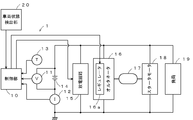
- FIG. 1 is a diagram illustrating a power supply system of a vehicle having a charge control device according to an embodiment of the present invention.
- the charge control apparatus 1 of this embodiment has the control part 10, the voltage sensor 11, the current sensor 12, the temperature sensor 13, and the discharge circuit 15 as main components.
- the control unit 10 is configured to include a calculation unit and a control unit. However, the calculation unit and the control unit may be configured separately.
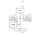
- FIG. 2 is a diagram illustrating a detailed configuration example of the control unit 10.
- the control unit 10 includes a CPU (Central Processing Unit) 10a, a ROM (Read Only Memory) 10b, a RAM (Random Access Memory) 10c, an output unit 10d, a bus 10e, and an I / F (Interface). ) 10f.
- the CPU 10a controls each unit based on the program 10ba stored in the ROM 10b.
- the ROM 10b is configured by a semiconductor memory or the like, and stores a program 10ba or the like.
- the RAM 10c is configured by a semiconductor memory or the like, and stores a parameter 10ca generated when the program 10ba is executed.
- the output unit 10 d supplies a pulse discharge ON / OFF control signal for measuring the internal resistance of the hybrid storage battery 14 to the discharge circuit 15 and supplies a generated voltage control signal to the regulator 16 a of the alternator 16.
- the bus 10e is a signal line group that enables the CPU 10a, the ROM 10b, the RAM 10c, the output unit 10d, and the I / F 10f to exchange data with each other.
- the I / F 10 f converts the signals supplied from the voltage sensor 11, the current sensor 12, the temperature sensor 13, and the vehicle state detection unit 20 into digital signals and takes them in.
- the voltage sensor 11 detects the terminal voltage of the hybrid storage battery 14 and notifies the control unit 10 of it.
- the current sensor 12 detects a charging current and a discharging current flowing through the hybrid storage battery 14 and notifies the control unit 10 of them.
- the temperature sensor 13 detects the hybrid storage battery 14 itself or the ambient environmental temperature and notifies the control unit 10 of it.
- the discharge circuit 15 is configured by, for example, a semiconductor switch that is turned on or off based on a pulse discharge ON / OFF control signal from the control unit 10.
- the discharge circuit 15 has two output terminals connected between the control signal line of the control unit 10 and the ground, and an input terminal connected to the control unit 10. When the pulse discharge ON / OFF control signal is high, the impedance is in a high impedance (off) state, and when the pulse discharge ON / OFF control signal is low, the impedance is in a low impedance (on) state.
- the hybrid storage battery 14 is configured, for example, by mixing a carbon material having conductivity on the surface of the negative electrode active material-filled plate and activated carbon having a capacitor capacity and a pseudo capacitor capacity, and a binder. It is comprised by the lead storage battery provided with the negative electrode plate which provided the coating layer of the carbon mixture as a negative electrode.
- the hybrid storage battery 14 is charged by the alternator 16, drives the starter motor 18 to start the engine 17, and supplies power to the load 19. Further, when the vehicle is decelerated, it is charged with electric power regenerated by the alternator 16.
- the alternator 16 is driven by the rotational force of the engine 17 or the inertial force at the time of deceleration of the vehicle, generates AC power, converts it into DC power by a rectifier circuit, and adjusts the voltage by the regulator 16a.
- Charge In the present invention, by using the hybrid storage battery 14, it can be configured by a single power storage device, and there is no need to mount two or more types of secondary batteries or capacitors. Therefore, compared to a charge control device equipped with two or more kinds of power storage devices, a secondary battery, a voltage converter (for example, a DC / DC converter) and the like can be omitted, and the charge control device can be configured at low cost. .
- the vehicle state detection unit 20 detects vehicle speed, engine speed, accelerator opening, fuel cut signal, brake operation state, and the like, and notifies the control unit 10 of the detected vehicle state.
- the control unit 10 controls the regulator 16a according to the running state of the vehicle detected by the vehicle state detection unit 20 and the state of the hybrid storage battery 14 detected by the voltage sensor 11, the current sensor 12, and the temperature sensor 13. As a result, the power generation voltage of the alternator 16 is adjusted, and the state of charge of the hybrid storage battery 14 is controlled.
- the regulator 16 a controls the power generation voltage of the alternator 16 by controlling a current that flows through an excitation coil (not shown) of the alternator 16 in accordance with a control signal supplied from the control unit 10.
- the voltage generated by the alternator 16 is in a high voltage range when the generated voltage control signal output by the control unit 10 is high (Hi), and the generated voltage output by the control unit 10. When the control signal is low (Lo), the voltage range is low.
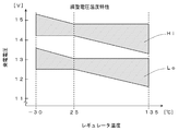
- FIG. 3 is a diagram showing the relationship between the ambient temperature (eg, case temperature) of the regulator 16a and the generated voltage.
- the hatched upper region shows a change in the generated voltage due to the temperature when the generated voltage control signal is high.
- the lower area where hatching is performed shows changes in the generated voltage due to temperature when the generated voltage control signal is low.
- the voltage range of the generated voltage of the alternator 16 varies depending on whether the generated voltage control signal supplied from the control unit 10 to the regulator 16a is high or low.
- the engine 17 is composed of, for example, a reciprocating engine such as a gasoline engine and a diesel engine, or a rotary engine, and is started by a starter motor 18 to drive driving wheels via a transmission to provide propulsive force to the vehicle. Drive to generate power.
- the starter motor 18 is constituted by, for example, a DC motor, and generates a rotational force by the electric power supplied from the hybrid storage battery 14 to start the engine 17.
- the load 19 is constituted by, for example, an electric steering motor, a defogger, an ignition coil, a car audio, a car navigation, and the like, and operates with electric power from the hybrid storage battery 14.
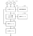
- FIG. 4 is a diagram showing processing modules realized by cooperation of hardware resources such as the CPU 10a and software resources such as the program 10ba when the program 10ba shown in FIG. 3 is executed.
- the processing module includes an input module 30, an SOC calculation module 31, a storage module 32, and an output module 34 as main components.
- the input module 30 inputs signals output from the voltage sensor 11, the current sensor 12, the temperature sensor 13, and the vehicle state detection unit 20, and supplies the signals to the SOC calculation module 31.
- the SOC calculation module 31 calculates the current SOC of the hybrid storage battery 14 based on the voltage, current, and temperature supplied from the input module 30 and supplies the obtained SOC to the determination module 33.
- an equivalent circuit model of the hybrid storage battery 14 is created, and the internal impedance is measured by performing pulsed discharge by the discharge circuit 15, and the parameter of the equivalent circuit model is calculated.
- the SOC is calculated based on the obtained parameters.
- an exponential function equation that approximates the time characteristic of the open circuit voltage of the hybrid storage battery 14 is obtained, the open circuit voltage at that time of the hybrid storage battery 14 is obtained from this exponential function equation, and the SOC is obtained from the obtained open circuit voltage. May be.
- the storage module 32 stores parameters necessary for the SOC calculation module 31 to calculate the SOC, an equivalent circuit model, and the like.
- the determination module 33 outputs control information based on the vehicle state detection unit 20 and the SOC to the output module 34.
- the output module 34 controls the regulator 16a and the like based on the output from the determination module 33.
- the lead storage battery is used at a low SOC, for example, the life of the lead storage battery is shortened due to the occurrence of sulfation, or the starter motor 18 does not rotate and the engine 17 does not start because the capacity is insufficient.
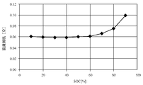
- FIG. 7 is an example showing the relationship between the internal resistance and the SOC during charging of the hybrid storage battery 14.
- the internal resistance is almost constant when the SOC is 60% or less, and the increase rate becomes large when the SOC is 70% or more.
- the SOC that can ensure engine startability varies greatly depending on the vehicle system. Generally, the SOC is set to a value of 50% or more. In the present embodiment, in consideration of these, the hybrid storage battery 14 is used to operate in a low SOC state, and regeneration is efficiently performed by the following control.
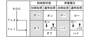
- FIG. 8 is a diagram showing the relationship between the state of the control signal and the generated voltage.
- the processing is different between the initial state immediately after the start of the engine 17 and the other normal state. Therefore, in the following, the operation in the initial state will be described first, and then the operation in the normal state will be described.
- the charging control device 1 executes an initial process.
- the initial process as shown on the left side of the “control unit state” in FIG. 8, when the SOC is equal to or higher than Th2 that is the second threshold value, the generated voltage control signal to the regulator 16 a is controlled to be in an ON state. 8, the power generation voltage of the alternator 16 is in a low state (Lo state in FIG. 3).
- Th2 which is the second threshold value
- the generated voltage control signal is controlled to be in an off state, and the generated voltage of the alternator 16 is in a high state (Hi state in FIG. 3).
- the generated voltage is set to the Hi state and is quickly charged.
- the process shifts to normal processing.
- charge control is executed based on a threshold value having hysteresis. Specifically, as shown at the left end of FIG. 8, the charging control is executed based on two threshold values, Th1 as the first threshold value and Th2 as the second threshold value.
- Th1 as the first threshold value
- Th2 as the second threshold value.
- the generated voltage control signal is controlled to be in the off state during the SOC rising phase.
- the power generation voltage of the alternator 16 is in a high state (Hi state in FIG. 3).
- the generated voltage control signal is controlled to be on, as shown on the right side of “generated voltage” in FIG.
- the generated voltage of the alternator 16 becomes low (the Lo state in FIG. 3).
- Th1 which is the first threshold value
- the generated voltage control signal to the regulator 16a is controlled to be on, and the generated voltage of the alternator 16 is low (see FIG. 3). Lo state).
- Th1 which is the first threshold value
- the generated voltage control signal to the regulator 16a is controlled to be off, and the generated voltage of the alternator 16 is high. (Hi state in FIG. 3).
- control is performed so that the SOC becomes equal to or higher than the second threshold value in the initial process immediately after the start of the engine 17, but when the process shifts to the normal process, the alternator 16 is controlled based on the first threshold value and the second threshold value.
- the generated voltage is controlled.
- the regulator 16a when the vehicle state detection unit 20 detects that the vehicle is in a decelerating state, the regulator 16a is controlled to set the output voltage of the alternator 16 to high. Thereby, since the charging current from the alternator 16 to the hybrid storage battery 14 increases, the kinetic energy of the vehicle can be converted into electric energy and stored in the hybrid storage battery 14.
- 70% and 71% can be used as the first threshold Th1 and the second threshold Th2, respectively.
- the hybrid storage battery 14 is less likely to deteriorate or become unable to start the engine 17 due to insufficient capacity even when the SOC is about 70%. For this reason, as shown in FIG. 5, the hybrid storage battery 14 can be used in a region where the charging efficiency is high. Therefore, not only when the alternator 16 is driven by the engine 17 and the hybrid storage battery 14 is charged, but also when the vehicle is decelerating.
- the hybrid storage battery 14 can be efficiently charged even when the kinetic energy of the vehicle is converted into electric energy by the alternator 16 and charged (when regenerating).
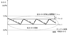
- the SOC of the hybrid storage battery 14 is controlled so as to be within the range of Th1 and Th2, as shown in FIG. More specifically, when the SOC falls below Th1, the output voltage of the alternator 16 is set to Hi and the SOC increases, and the SOC rises above Th2 when the SOC rises. In this case, the output voltage of the alternator 16 is set to Lo and the SOC decreases.
- the SOC of the hybrid storage battery 14 changes, for example, in a sawtooth shape as shown in FIG.
- the hybrid storage battery 14 is charged by the impulse waves shown in the portions of the sawtooth waveform.
- the thresholds Th1 and Th2 are set in a low SOC region where the upper limit is the low SOC region upper limit threshold Thu of the hybrid storage battery 14.
- the low SOC region refers to a low SOC region as compared to the 80 to 100% high SOC region where lead storage is generally operated. By operating in such a low SOC region, it is possible to improve power acceptability during regeneration.
- the low SOC region upper limit threshold value Thu is the time until the charging current flowing through the hybrid storage battery 14 starts to decrease from the maximum generated current after charging starts.
- the charging current is maximized in the range of Th1 to Th2, which is the SOC operating range. Since the time until it starts to decrease from the generated current becomes longer than 5 seconds, most of the regenerative power that lasts about several seconds can be stored in the hybrid storage battery 14 as electric power.
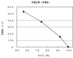
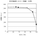
- FIG. 10 An example is shown in FIG. In FIG. 10, the SOC of one secondary battery is adjusted to 50%, 70%, 90%, and 100%, and the secondary battery of each SOC flows to the secondary battery when charged with a constant current of 120A.
- the relationship between current and charging time is shown.
- the maximum voltage of the constant current source is 16.0V, and charging is started from 0 sec in FIG.
- the SOC 90% and 100%, the current greatly decreases immediately after the start of charging.
- the SOC is 70%
- a current of 120 A can flow for about 5 seconds from the start of charging.
- the SOC is 50%
- the set current 120A can be supplied for 180 seconds or more.
- a predetermined charging time from the start of charging is determined, and during this time, the SOC region can be set to the low SOC region by passing the set current.
- the low SOC region upper limit threshold value Thu is, for example, based on the relationship between the internal resistance of the hybrid storage battery 14 (DC resistance shown in FIG. 7) and the SOC, and the internal resistance becomes a predetermined value or less.
- the SOC may be set to the low SOC region upper limit threshold Thu.
- 70% since the increase rate becomes large when the SOC is 70% or more, 70% may be selected as the low SOC region upper limit threshold Thu.
- the charging current when a predetermined time has elapsed from the start of charging is a predetermined value (for example, the current after 5 seconds from the start of charging is 100 A or more or 90% or more of the maximum current of the alternator 16) May be set as the low SOC region upper limit threshold value Thu.
- the maximum SOC (approximately 70% in the example of FIG.
- FIG. 11 is a diagram illustrating an example of change in SOC when the first threshold Th1 is set to 70% and the second threshold Th2 is set to 71%.
- the horizontal axis indicates time (seconds).
- the SOC of the hybrid storage battery 14 becomes 70% or less, which is the first threshold Th ⁇ b> 1 (near 1600 (s) shown in FIG. 11), regardless of the traveling state of the vehicle.
- the output voltage of the alternator 16 is set to a high state, and the hybrid storage battery 14 is rapidly charged so that the SOC of the hybrid storage battery 14 becomes 71% or more.
- the SOC of the hybrid storage battery 14 is controlled to be within the range of 70 to 71%, and when it becomes less than 70%, it can be charged rapidly. Further, when the SOC of the hybrid storage battery 14 is within the range of 70 to 71%, the regeneration can be efficiently performed by setting the regulator 16a to the high state when the vehicle is decelerated.
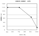
- FIG. 12 shows measured values when the charge control device of the present invention is mounted on an actual vehicle.
- the vertical axis indicates fuel consumption.
- the actual vehicle A shows a case where the charging control device of the present invention is not installed
- the actual vehicle B shows a case where the charging control device of the present invention is installed.
- the fuel consumption is improved by about 1.36% compared to the case where the charging control device is not mounted.
- the effect of the charge control device of the present invention is obtained.
- step S10 the input module 30 inputs the voltage V, the current I, and the temperature T from the voltage sensor 11, the current sensor 12, and the temperature sensor 13, respectively.
- step S11 the SOC calculation module 31 performs a process of calculating the SOC of the hybrid storage battery 14 based on the voltage V, current I, temperature T input in step S10, and data stored in the storage module 32. .
- adaptive learning using, for example, a Kalman filter is applied to the equivalent circuit model of the hybrid storage battery 14, and the obtained value (for example, OCV (Open Circuit Voltage: open This can be realized by calculating the SOC based on the circuit voltage)).
- OCV Open Circuit Voltage: open This can be realized by calculating the SOC based on the circuit voltage
- step S12 the input module 30 inputs information indicating the state of the vehicle from the vehicle state detection unit 20.
- the vehicle state detection unit 20 detects the vehicle speed, the engine speed, the accelerator opening, the fuel cut signal, the brake operation state, and the like, and supplies them to the input module 30.
- step S13 the determination module 33 refers to the information indicating the vehicle state acquired in step S12, determines whether or not the vehicle is in a deceleration state (a state in which regeneration is possible), and determines that the vehicle is in a deceleration state ( In step S13: Yes, the process proceeds to step S14 where the power generation voltage is set to a high state to perform regenerative charging. In other cases (step S13: No), the process proceeds to step S15. For example, if the vehicle speed is greater than 5 km / h, the accelerator opening is less than 10%, and the fuel cut instruction signal is high, it is determined that the vehicle is decelerating and the process proceeds to step S14. Otherwise, the process proceeds to step S15.
- the fuel cut instruction signal is a signal for instructing to cut (stop) the fuel to be supplied to the engine 17, and indicates that no fuel is supplied to the engine 17 when this signal is turned on.
- the determination criterion described above is an example, and it may be determined whether the vehicle is in a deceleration state based on other information. For example, if the fuel cut instruction signal is in a high state only during deceleration, the determination may be made based only on the fuel cut instruction signal and the vehicle speed. Of course, the determination may be made in consideration of the rotational speed of the engine 17 or the like. Further, even when it is determined that the vehicle is decelerating, regenerative charging may be stopped when any of the conditions is not satisfied. Thereby, it is possible to prevent an unnecessary load from being applied to the engine 17.
- step S14 the output module 34 sets the regulator 16a to a high state. Thereby, the output voltage of the alternator 16 is set to a high state, and charging (regenerative charging) of the hybrid storage battery 14 by kinetic energy at the time of deceleration of the vehicle is executed.
- step S14 the process ends.
- step S17 the output module 34 sets the regulator 16a to a high state. As a result, the output voltage of the alternator 16 is set to a high state, and the hybrid storage battery 14 is charged by the driving force of the engine 17.
- step S19 the process proceeds to step S19.
- step S18 the output module 34 sets the regulator 16a to a low state. As a result, the output voltage of the alternator 16 is set to a low state.
- step S21 the output module 34 sets the regulator 16a to a low state. As a result, the output voltage of the alternator 16 is set to a low state.
- step S23 the output module 34 sets the regulator 16a to a high state. Thereby, the output voltage of the alternator 16 is set to a high state.
- step S24 the output module 34 sets the previous power generation voltage as the power generation voltage of the regulator 16a. Specifically, when the previous power generation voltage is low, it is set to low, and when it is high, it is set to high. As a result, when the SOC exists in the range of Th1 ⁇ SOC ⁇ Th2, the previous value is used. Therefore, as shown in FIG. 8, the output voltage of the alternator 16 is the same in the rising phase or the falling phase. Maintained.
- step S25 the determination module 33 sets the current power generation voltage as the previous power generation voltage. Specifically, if the current power generation voltage is low, it is set to low, and if it is high, it is set to high.
- the SOC in the first process after the engine 17 is started, the SOC is referred to, and the voltage of the alternator 16 is set to a high state so that the SOC of the hybrid storage battery 14 is 71% or more. Is done.
- the generated voltage when the SOC is 71% or more, the generated voltage is set to low, when the SOC is 70% or less, it is set to high, and when it is greater than 70% and less than 71%. The previous generated voltage is maintained. Thereby, the voltage setting shown in FIG. 8 becomes possible. Moreover, chattering can be prevented from occurring by providing two threshold values and performing control based on hysteresis.
- the power generation voltage is set to high and regeneration is performed, so that fuel consumption can be improved.
- the charge control device 1 includes the voltage sensor 11, the current sensor 12, and the temperature sensor 13, and the SOC is calculated in real time.
- the SOC is calculated in real time.
- Th1 and Th2 it is known from actual measurement results that the smaller the difference between Th1 and Th2, the better the fuel consumption. Therefore, it is desirable to set the difference between Th1 and Th2 as small as possible.
- the interval between Th1 and Th2 is less than 10%, preferably less than several percent.
- Th1 and Th2 are fixed values. For example, these values may be rewritable. By setting it as such a structure, you may enable it to adjust these values suitably according to the kind and use purpose of the hybrid storage battery 14, for example. Moreover, the capacity
- the second threshold value in the normal process is used as the threshold value in the initial process.
- the threshold value in the initial process may be different from the second threshold value. For example, by using a value larger than the second threshold, it is possible to rapidly charge up to a certain SOC in the initial process.
- the threshold value for the initial process to the second threshold value, the transition from the initial process to the normal process can be performed smoothly.
- the alternator 16 can set two types of voltages, high and low.
- an alternator that can output a desired voltage according to the generated voltage signal is used. You may make it use.
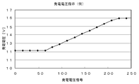
- the generated voltage signal is in the range of 0 to about 60 and is a little over 11V, and in the range of 60 to 220, the voltage rises according to the value of the signal.
- an alternator when used, for example, it can be set to 12.0 ⁇ 0.5 V when the vehicle is accelerating or traveling at a constant speed, and can be set to 15.0 V or more when the vehicle is decelerating.
- the generated voltage is set to 12.0 ⁇ 0.5V
- the generated voltage is set to 14.5V.
- FIG. 15 shows the relationship between the SOC and voltage when the vehicle is traveling at a constant speed or accelerating.
- the alternator voltage indicated by the broken line is set higher than the voltage of the hybrid storage battery, and when the SOC is greater than 60%, the voltage of the hybrid storage battery is It is set to be higher than the voltage of the alternator. At this time, the voltage difference between the hybrid storage battery and the alternator is set to be constant.
- FIG. 16 shows the relationship between SOC and voltage during deceleration. In the example of FIG.
- the voltage difference between the hybrid storage battery and the alternator is set so as to decrease as the SOC value increases. More specifically, the generated voltage of the alternator may be controlled so that the voltage difference between the reference voltage and the alternator indicated by the alternate long and short dash line is equal to the voltage difference between the reference voltage and the hybrid storage battery.
- the difference voltage between the terminal voltage of the hybrid storage battery 14 and the reference voltage can be obtained, and the output voltage of the alternator 16 can be controlled to be equal to the voltage obtained by adding the difference voltage to the reference voltage.
- the electric power is supplied from the hybrid storage battery 14 to the load 19 by setting the voltage of the alternator 16 lower than the terminal voltage of the hybrid storage battery 14. May be reliably supplied.
- the hybrid storage battery 14 since the hybrid storage battery 14 has a voltage lower than that of a normal lead storage battery, such control is effective.
- the detection value of the temperature sensor 13 is not described in detail. However, since the characteristics of the hybrid storage battery 14 vary depending on the ambient temperature, the SOC calculated based on the output of the temperature sensor 13 is calculated. You may make it correct
- the SOC range and the reference value are fixed values. However, for example, these values may be changed according to the state of the hybrid storage battery 14 (for example, the deterioration state). Specifically, when the hybrid storage battery 14 is deteriorated, the capacity is reduced. Therefore, in order to obtain the same capacity as in the new case, it is necessary to set a wide SOC range.
- FIG. 17 is a diagram showing the relationship between the current value at 5 seconds from the start of charging and the SOC when a lead storage battery different from FIG. 6 is charged with a charging current of 100 A.
- FIG. 18 is a diagram showing the relationship between the charge amount (As) for 5 seconds from the start of charging and the SOC when the same lead storage battery as in FIG. 17 is charged with a charging current of 100 A.
- the SOC exceeds 80%, the charging current and the charging amount decrease. Therefore, in the lead storage battery shown in FIGS.
- 80 to 85% can be selected as the low SOC region upper limit threshold value Thu.
- the low SOC region upper limit threshold Thu it is desirable to set the low SOC region upper limit threshold Thu to a value of about 80 to 85% or smaller.
- the margin m shown in FIG. 9 can be set to a value of about several percent, for example. Of course, the value may be larger than this, or may be smaller than this including 0.
- a plurality of power storage devices for example, lithium batteries, nickel batteries, nickel metal hydride batteries, capacitors, etc.
- a hybrid storage battery for example, lithium batteries, nickel batteries, nickel metal hydride batteries, capacitors, etc.
- SYMBOLS 1 Charge control apparatus 10 Control part (calculation means, control means) 10a CPU 10b ROM 10c RAM 10d communication unit 10e bus 10f I / F 11 Voltage sensor (calculation means) 12 Current sensor (calculation means) 13 Temperature sensor (calculation means) 14 Hybrid storage battery (secondary battery) DESCRIPTION OF SYMBOLS 15 Discharge circuit 16 Alternator 16a Regulator 17 Engine 18 Starter motor 19 Load 20 Vehicle state detection part (detection means)
Landscapes
- Engineering & Computer Science (AREA)
- Transportation (AREA)
- Mechanical Engineering (AREA)
- Power Engineering (AREA)
- Chemical & Material Sciences (AREA)
- Combustion & Propulsion (AREA)
- Automation & Control Theory (AREA)
- Chemical Kinetics & Catalysis (AREA)
- Manufacturing & Machinery (AREA)
- Electrochemistry (AREA)
- General Chemical & Material Sciences (AREA)
- Life Sciences & Earth Sciences (AREA)
- Sustainable Development (AREA)
- Sustainable Energy (AREA)
- Charge And Discharge Circuits For Batteries Or The Like (AREA)
- Secondary Cells (AREA)
- Control Of Charge By Means Of Generators (AREA)
Abstract
Le problème résolu par l'invention consiste à effectuer efficacement la commande charge et la commande de régénération pour une batterie secondaire. La solution décrite par la présente invention concerne un dispositif de commande de charge comportant des moyens de calcul (capteur de tension (11), capteur de courant (12), unité de commande (10)) pour calculer l'état de charge d'une batterie secondaire, des moyens de détection (détecteur d'état de véhicule (20)) pour détecter l'état de déplacement d'un véhicule et des moyens de commande (unité de commande (10)). Quand un état de ralentissement est détecté, les moyens de commande exécutent une commande de charge de la batterie secondaire avec une puissance de régénération en réglant la tension générée par un alternateur à une valeur supérieure à la tension aux bornes de la batterie secondaire. Quand il est détecté que le véhicule est dans un état autre que l'état de ralentissement et que le taux de charge est supérieur à une seconde valeur de seuil déterminée, l'unité de commande exécute une commande de manière à régler la tension générée par l'alternateur à une valeur inférieure à la tension aux bornes de la batterie secondaire, et quand le taux de charge est inférieur à une première valeur de seuil déterminée, l'unité de commande exécute une commande de manière à régler la tension générée par l'alternateur à une valeur supérieure à la tension aux bornes de la batterie secondaire. La seconde valeur de seuil est supérieur à la première valeur de seuil, et les première et seconde valeurs de seuil sont dans région basse de l'état de charge.
Priority Applications (3)
| Application Number | Priority Date | Filing Date | Title |
|---|---|---|---|
| JP2015521441A JP6239611B2 (ja) | 2013-06-03 | 2014-06-02 | 充電制御装置および充電制御方法 |
| EP14806861.2A EP2993758A4 (fr) | 2013-06-03 | 2014-06-02 | Dispositif et procédé de commande de charge |
| US14/957,590 US9855854B2 (en) | 2013-06-03 | 2015-12-02 | Charge control device and charge control method |
Applications Claiming Priority (2)
| Application Number | Priority Date | Filing Date | Title |
|---|---|---|---|
| JP2013116667 | 2013-06-03 | ||
| JP2013-116667 | 2013-06-03 |
Related Child Applications (1)
| Application Number | Title | Priority Date | Filing Date |
|---|---|---|---|
| US14/957,590 Continuation US9855854B2 (en) | 2013-06-03 | 2015-12-02 | Charge control device and charge control method |
Publications (1)
| Publication Number | Publication Date |
|---|---|
| WO2014196506A1 true WO2014196506A1 (fr) | 2014-12-11 |
Family
ID=52008147
Family Applications (1)
| Application Number | Title | Priority Date | Filing Date |
|---|---|---|---|
| PCT/JP2014/064656 WO2014196506A1 (fr) | 2013-06-03 | 2014-06-02 | Dispositif et procédé de commande de charge |
Country Status (4)
| Country | Link |
|---|---|
| US (1) | US9855854B2 (fr) |
| EP (1) | EP2993758A4 (fr) |
| JP (1) | JP6239611B2 (fr) |
| WO (1) | WO2014196506A1 (fr) |
Cited By (10)
| Publication number | Priority date | Publication date | Assignee | Title |
|---|---|---|---|---|
| JP2016115521A (ja) * | 2014-12-15 | 2016-06-23 | トヨタ自動車株式会社 | 充電装置 |
| WO2017112089A1 (fr) * | 2015-12-21 | 2017-06-29 | Intel Corporation | Systèmes et procédés pour fin de charge adaptative |
| JP2017184557A (ja) * | 2016-03-31 | 2017-10-05 | トヨタ自動車株式会社 | 車両用制御装置 |
| JP2018121482A (ja) * | 2017-01-27 | 2018-08-02 | トヨタ自動車株式会社 | 電源装置 |
| JP2019097353A (ja) * | 2017-11-27 | 2019-06-20 | トヨタ自動車株式会社 | 発電機の制御装置 |
| CN113451671A (zh) * | 2019-02-01 | 2021-09-28 | 神讯电脑(昆山)有限公司 | 备用电池模块的充电方法及电子装置 |
| JP2022124200A (ja) * | 2021-02-15 | 2022-08-25 | トヨタ自動車株式会社 | 車両の制御装置 |
| WO2022229524A1 (fr) * | 2021-04-30 | 2022-11-03 | Psa Automobiles Sa | Gestion stratégique d'un groupe d'alimentation électrique d'un véhicule en fonction d'informations concernant la batterie de servitude |
| DE112016001745B4 (de) | 2015-04-14 | 2023-02-16 | Calsonic Kansei Corporation | Steuereinheit für generator, verfahren zur steuerung des antreibens eines generators und leistungsquellenverwaltungssystem in einem motorfahrzeug |
| WO2024063207A1 (fr) * | 2022-09-19 | 2024-03-28 | 주식회사 엘지에너지솔루션 | Dispositif d'estimation de l'état d'un véhicule et son procédé de fonctionnement |
Families Citing this family (18)
| Publication number | Priority date | Publication date | Assignee | Title |
|---|---|---|---|---|
| WO2015112153A1 (fr) * | 2014-01-24 | 2015-07-30 | Volvo Truck Corporation | Contrôleur de charge de batterie pour unité de commande électronique du moteur |
| EP3100337B1 (fr) * | 2014-01-27 | 2022-01-12 | Otis Elevator Company | Algorithme de charge pour ascenseur propulsé à l'aide d'une batterie |
| US11104231B2 (en) * | 2014-04-17 | 2021-08-31 | Michael Lynn Froelich | System for maintaining acceptable battery cycle life for electric-powered vehicles |
| US10320202B2 (en) * | 2014-09-30 | 2019-06-11 | Johnson Controls Technology Company | Battery system bi-stable relay control |
| US9950704B2 (en) * | 2014-11-04 | 2018-04-24 | Honda Motor Co., Ltd. | Device and method for charging control |
| US10224579B2 (en) | 2015-12-31 | 2019-03-05 | Robert Bosch Gmbh | Evaluating capacity fade in dual insertion batteries using potential and temperature measurements |
| US10243385B2 (en) * | 2016-01-29 | 2019-03-26 | Robert Bosch Gmbh | Secondary battery management system |
| US10263447B2 (en) | 2016-01-29 | 2019-04-16 | Robert Bosch Gmbh | Secondary battery management system |
| US10686321B2 (en) | 2016-01-29 | 2020-06-16 | Robert Bosch Gmbh | Secondary battery management |
| US10447046B2 (en) | 2016-09-22 | 2019-10-15 | Robert Bosch Gmbh | Secondary battery management system with remote parameter estimation |
| US9796291B1 (en) * | 2016-11-09 | 2017-10-24 | Ford Global Technologies, Llc | Low charge acceptance mitigation using a traction battery |
| JP2019004595A (ja) * | 2017-06-14 | 2019-01-10 | 本田技研工業株式会社 | 車両の電源装置 |
| US10439427B2 (en) * | 2017-08-03 | 2019-10-08 | Ford Global Technologies, Llc | Determining a fuel quantity to charge a vehicle battery |
| CN107856559A (zh) * | 2017-10-24 | 2018-03-30 | 西北工业大学 | 一种电动汽车的动力电池管理系统 |
| CA3089472C (fr) | 2018-01-23 | 2023-08-01 | Iotecha Corp. | Procede et appareil de charge d'une batterie avec une alimentation en courant alternatif sur la base d'informations relatives a l'etat de la batterie |
| DE102018203015B3 (de) * | 2018-02-28 | 2019-05-09 | Siemens Aktiengesellschaft | Verfahren zur Regelung eines Batteriestroms einer Traktionsbatterie |
| CN109204338B (zh) * | 2018-09-17 | 2020-02-18 | 武汉新时代铁路电气有限责任公司 | 一种轨道车辆蓄电池智能充电装置 |
| CN112606781B (zh) * | 2020-12-28 | 2023-03-31 | 卢浩义 | 电子控制型起动电池及其控制和应用方法 |
Citations (13)
| Publication number | Priority date | Publication date | Assignee | Title |
|---|---|---|---|---|
| JP2000175306A (ja) * | 1998-12-07 | 2000-06-23 | Honda Motor Co Ltd | ハイブリッド車両の制御装置 |
| JP2006002626A (ja) | 2004-06-16 | 2006-01-05 | Mitsubishi Motors Corp | 車両用電源装置 |
| JP2007230513A (ja) * | 2006-03-03 | 2007-09-13 | Fujitsu Ten Ltd | 発電制御装置、及びその方法 |
| JP2007318888A (ja) | 2006-05-25 | 2007-12-06 | Nissan Motor Co Ltd | バッテリの充電状態制御装置 |
| JP2009180125A (ja) * | 2008-01-30 | 2009-08-13 | Daihatsu Motor Co Ltd | 車両用電源制御装置 |
| JP2010017060A (ja) * | 2008-07-07 | 2010-01-21 | Toyota Motor Corp | 車両用電源システム |
| JP2010119176A (ja) | 2008-11-12 | 2010-05-27 | Mitsubishi Electric Corp | 車載用電源装置 |
| JP2010217079A (ja) * | 2009-03-18 | 2010-09-30 | Nissan Motor Co Ltd | 二次電池の総容量推定装置 |
| JP2010241185A (ja) * | 2009-04-02 | 2010-10-28 | Hitachi Automotive Systems Ltd | ハイブリッド車両の充電制御装置 |
| JP2010283959A (ja) | 2009-06-03 | 2010-12-16 | Toyota Motor Corp | 車両用発電制御装置 |
| JP2011106953A (ja) * | 2009-11-17 | 2011-06-02 | Honda Motor Co Ltd | 電池容量検出方法 |
| JP2013090450A (ja) * | 2011-10-18 | 2013-05-13 | Toyota Motor Corp | 車両の充電制御装置、及び、車両の制御装置 |
| JP2013101058A (ja) * | 2011-11-09 | 2013-05-23 | Furukawa Electric Co Ltd:The | 二次電池状態検出システム |
Family Cites Families (7)
| Publication number | Priority date | Publication date | Assignee | Title |
|---|---|---|---|---|
| DE102004055128A1 (de) * | 2004-11-16 | 2006-06-01 | Volkswagen Ag | Verfahren zur Steuerung eines Betriebs eines Hybridkraftfahrzeugs sowie Hybridfahrzeug |
| JP4375458B2 (ja) * | 2007-08-01 | 2009-12-02 | 株式会社デンソー | 2次電池の充電状態推定装置及び充電制御システム |
| JP5217430B2 (ja) * | 2007-12-28 | 2013-06-19 | トヨタ自動車株式会社 | オルタネータ制御装置およびオルタネータ制御方法 |
| US8217631B2 (en) * | 2008-01-22 | 2012-07-10 | Honda Motor Co., Ltd. | ACG output voltage control |
| JP5520629B2 (ja) * | 2010-02-12 | 2014-06-11 | 富士重工業株式会社 | 車両用電源装置 |
| US9340121B2 (en) * | 2011-04-14 | 2016-05-17 | GM Global Technology Operations LLC | Method and system for heating a vehicle battery |
| CN102381314B (zh) * | 2011-10-10 | 2014-03-12 | 重庆长安汽车股份有限公司 | 一种混合动力汽车充放电控制方法 |
-
2014
- 2014-06-02 WO PCT/JP2014/064656 patent/WO2014196506A1/fr active Application Filing
- 2014-06-02 JP JP2015521441A patent/JP6239611B2/ja active Active
- 2014-06-02 EP EP14806861.2A patent/EP2993758A4/fr active Pending
-
2015
- 2015-12-02 US US14/957,590 patent/US9855854B2/en active Active
Patent Citations (13)
| Publication number | Priority date | Publication date | Assignee | Title |
|---|---|---|---|---|
| JP2000175306A (ja) * | 1998-12-07 | 2000-06-23 | Honda Motor Co Ltd | ハイブリッド車両の制御装置 |
| JP2006002626A (ja) | 2004-06-16 | 2006-01-05 | Mitsubishi Motors Corp | 車両用電源装置 |
| JP2007230513A (ja) * | 2006-03-03 | 2007-09-13 | Fujitsu Ten Ltd | 発電制御装置、及びその方法 |
| JP2007318888A (ja) | 2006-05-25 | 2007-12-06 | Nissan Motor Co Ltd | バッテリの充電状態制御装置 |
| JP2009180125A (ja) * | 2008-01-30 | 2009-08-13 | Daihatsu Motor Co Ltd | 車両用電源制御装置 |
| JP2010017060A (ja) * | 2008-07-07 | 2010-01-21 | Toyota Motor Corp | 車両用電源システム |
| JP2010119176A (ja) | 2008-11-12 | 2010-05-27 | Mitsubishi Electric Corp | 車載用電源装置 |
| JP2010217079A (ja) * | 2009-03-18 | 2010-09-30 | Nissan Motor Co Ltd | 二次電池の総容量推定装置 |
| JP2010241185A (ja) * | 2009-04-02 | 2010-10-28 | Hitachi Automotive Systems Ltd | ハイブリッド車両の充電制御装置 |
| JP2010283959A (ja) | 2009-06-03 | 2010-12-16 | Toyota Motor Corp | 車両用発電制御装置 |
| JP2011106953A (ja) * | 2009-11-17 | 2011-06-02 | Honda Motor Co Ltd | 電池容量検出方法 |
| JP2013090450A (ja) * | 2011-10-18 | 2013-05-13 | Toyota Motor Corp | 車両の充電制御装置、及び、車両の制御装置 |
| JP2013101058A (ja) * | 2011-11-09 | 2013-05-23 | Furukawa Electric Co Ltd:The | 二次電池状態検出システム |
Non-Patent Citations (1)
| Title |
|---|
| See also references of EP2993758A4 |
Cited By (14)
| Publication number | Priority date | Publication date | Assignee | Title |
|---|---|---|---|---|
| JP2016115521A (ja) * | 2014-12-15 | 2016-06-23 | トヨタ自動車株式会社 | 充電装置 |
| DE112016001745B4 (de) | 2015-04-14 | 2023-02-16 | Calsonic Kansei Corporation | Steuereinheit für generator, verfahren zur steuerung des antreibens eines generators und leistungsquellenverwaltungssystem in einem motorfahrzeug |
| WO2017112089A1 (fr) * | 2015-12-21 | 2017-06-29 | Intel Corporation | Systèmes et procédés pour fin de charge adaptative |
| US10122205B2 (en) | 2015-12-21 | 2018-11-06 | Intel Corporation | Systems and methods for adaptive charge termination |
| JP2017184557A (ja) * | 2016-03-31 | 2017-10-05 | トヨタ自動車株式会社 | 車両用制御装置 |
| JP2018121482A (ja) * | 2017-01-27 | 2018-08-02 | トヨタ自動車株式会社 | 電源装置 |
| JP2019097353A (ja) * | 2017-11-27 | 2019-06-20 | トヨタ自動車株式会社 | 発電機の制御装置 |
| JP7004147B2 (ja) | 2017-11-27 | 2022-01-21 | トヨタ自動車株式会社 | 発電機の制御装置 |
| CN113451671A (zh) * | 2019-02-01 | 2021-09-28 | 神讯电脑(昆山)有限公司 | 备用电池模块的充电方法及电子装置 |
| JP2022124200A (ja) * | 2021-02-15 | 2022-08-25 | トヨタ自動車株式会社 | 車両の制御装置 |
| JP7306415B2 (ja) | 2021-02-15 | 2023-07-11 | トヨタ自動車株式会社 | 車両の制御装置 |
| WO2022229524A1 (fr) * | 2021-04-30 | 2022-11-03 | Psa Automobiles Sa | Gestion stratégique d'un groupe d'alimentation électrique d'un véhicule en fonction d'informations concernant la batterie de servitude |
| FR3122367A1 (fr) * | 2021-04-30 | 2022-11-04 | Psa Automobiles Sa | Gestion stratégique d’un groupe d’alimentation électrique d’un véhicule en fonction d’informations concernant la batterie de servitude |
| WO2024063207A1 (fr) * | 2022-09-19 | 2024-03-28 | 주식회사 엘지에너지솔루션 | Dispositif d'estimation de l'état d'un véhicule et son procédé de fonctionnement |
Also Published As
| Publication number | Publication date |
|---|---|
| JP6239611B2 (ja) | 2017-11-29 |
| EP2993758A4 (fr) | 2016-11-02 |
| US9855854B2 (en) | 2018-01-02 |
| JPWO2014196506A1 (ja) | 2017-02-23 |
| US20160090001A1 (en) | 2016-03-31 |
| EP2993758A1 (fr) | 2016-03-09 |
Similar Documents
| Publication | Publication Date | Title |
|---|---|---|
| JP6239611B2 (ja) | 充電制御装置および充電制御方法 | |
| JP5356439B2 (ja) | 充電制御装置および充電制御方法 | |
| JP4209423B2 (ja) | 二次電池用の制御装置及び二次電池の出力制御方法 | |
| JP5029331B2 (ja) | 車両用電源装置 | |
| US6982540B2 (en) | Energy management system for a motor vehicle electrical system | |
| CN102447140B (zh) | 锂离子电池的控制装置 | |
| JP4572998B2 (ja) | リチウムイオン二次電池の充電方法、及び、ハイブリッド自動車 | |
| CN103660961B (zh) | 车辆用电源的控制装置及控制方法 | |
| JP5211954B2 (ja) | 車両用電源装置 | |
| US20160167534A1 (en) | Charging apparatus | |
| JP2012080689A (ja) | 電気自動車用電源装置 | |
| CN109314399B (zh) | 车载电源系统 | |
| US10498154B2 (en) | Electric power system | |
| JP7373113B2 (ja) | 車両用電源制御装置 | |
| JP2020103006A (ja) | 車両用充電制御システム | |
| JP2020038782A (ja) | 電源制御装置 | |
| JP5911897B2 (ja) | 二次電池充電制御装置および二次電池充電制御方法 | |
| JP5639119B2 (ja) | 充電装置および充電方法 | |
| JP6189105B2 (ja) | 電源装置 | |
| JP2017103971A (ja) | バッテリーの制御システム、ハイブリッド車両及びバッテリーの制御方法 | |
| JP6295942B2 (ja) | 充電装置 | |
| JP6469408B2 (ja) | 二次電池充電制御装置および二次電池充電制御方法 | |
| JP2015012683A (ja) | 電源装置 |
Legal Events
| Date | Code | Title | Description |
|---|---|---|---|
| 121 | Ep: the epo has been informed by wipo that ep was designated in this application |
Ref document number: 14806861 Country of ref document: EP Kind code of ref document: A1 |
|
| ENP | Entry into the national phase |
Ref document number: 2015521441 Country of ref document: JP Kind code of ref document: A |
|
| WWE | Wipo information: entry into national phase |
Ref document number: 2014806861 Country of ref document: EP |
|
| NENP | Non-entry into the national phase |
Ref country code: DE |