WO2014196506A1 - 充電制御装置および充電制御方法 - Google Patents
充電制御装置および充電制御方法 Download PDFInfo
- Publication number
- WO2014196506A1 WO2014196506A1 PCT/JP2014/064656 JP2014064656W WO2014196506A1 WO 2014196506 A1 WO2014196506 A1 WO 2014196506A1 JP 2014064656 W JP2014064656 W JP 2014064656W WO 2014196506 A1 WO2014196506 A1 WO 2014196506A1
- Authority
- WO
- WIPO (PCT)
- Prior art keywords
- secondary battery
- voltage
- vehicle
- alternator
- state
- Prior art date
Links
Images


Classifications
-
- B—PERFORMING OPERATIONS; TRANSPORTING
- B60—VEHICLES IN GENERAL
- B60L—PROPULSION OF ELECTRICALLY-PROPELLED VEHICLES; SUPPLYING ELECTRIC POWER FOR AUXILIARY EQUIPMENT OF ELECTRICALLY-PROPELLED VEHICLES; ELECTRODYNAMIC BRAKE SYSTEMS FOR VEHICLES IN GENERAL; MAGNETIC SUSPENSION OR LEVITATION FOR VEHICLES; MONITORING OPERATING VARIABLES OF ELECTRICALLY-PROPELLED VEHICLES; ELECTRIC SAFETY DEVICES FOR ELECTRICALLY-PROPELLED VEHICLES
- B60L1/00—Supplying electric power to auxiliary equipment of vehicles
- B60L1/003—Supplying electric power to auxiliary equipment of vehicles to auxiliary motors, e.g. for pumps, compressors
-
- B—PERFORMING OPERATIONS; TRANSPORTING
- B60—VEHICLES IN GENERAL
- B60L—PROPULSION OF ELECTRICALLY-PROPELLED VEHICLES; SUPPLYING ELECTRIC POWER FOR AUXILIARY EQUIPMENT OF ELECTRICALLY-PROPELLED VEHICLES; ELECTRODYNAMIC BRAKE SYSTEMS FOR VEHICLES IN GENERAL; MAGNETIC SUSPENSION OR LEVITATION FOR VEHICLES; MONITORING OPERATING VARIABLES OF ELECTRICALLY-PROPELLED VEHICLES; ELECTRIC SAFETY DEVICES FOR ELECTRICALLY-PROPELLED VEHICLES
- B60L15/00—Methods, circuits, or devices for controlling the traction-motor speed of electrically-propelled vehicles
- B60L15/20—Methods, circuits, or devices for controlling the traction-motor speed of electrically-propelled vehicles for control of the vehicle or its driving motor to achieve a desired performance, e.g. speed, torque, programmed variation of speed
-
- B—PERFORMING OPERATIONS; TRANSPORTING
- B60—VEHICLES IN GENERAL
- B60L—PROPULSION OF ELECTRICALLY-PROPELLED VEHICLES; SUPPLYING ELECTRIC POWER FOR AUXILIARY EQUIPMENT OF ELECTRICALLY-PROPELLED VEHICLES; ELECTRODYNAMIC BRAKE SYSTEMS FOR VEHICLES IN GENERAL; MAGNETIC SUSPENSION OR LEVITATION FOR VEHICLES; MONITORING OPERATING VARIABLES OF ELECTRICALLY-PROPELLED VEHICLES; ELECTRIC SAFETY DEVICES FOR ELECTRICALLY-PROPELLED VEHICLES
- B60L50/00—Electric propulsion with power supplied within the vehicle
- B60L50/10—Electric propulsion with power supplied within the vehicle using propulsion power supplied by engine-driven generators, e.g. generators driven by combustion engines
- B60L50/16—Electric propulsion with power supplied within the vehicle using propulsion power supplied by engine-driven generators, e.g. generators driven by combustion engines with provision for separate direct mechanical propulsion
-
- B—PERFORMING OPERATIONS; TRANSPORTING
- B60—VEHICLES IN GENERAL
- B60L—PROPULSION OF ELECTRICALLY-PROPELLED VEHICLES; SUPPLYING ELECTRIC POWER FOR AUXILIARY EQUIPMENT OF ELECTRICALLY-PROPELLED VEHICLES; ELECTRODYNAMIC BRAKE SYSTEMS FOR VEHICLES IN GENERAL; MAGNETIC SUSPENSION OR LEVITATION FOR VEHICLES; MONITORING OPERATING VARIABLES OF ELECTRICALLY-PROPELLED VEHICLES; ELECTRIC SAFETY DEVICES FOR ELECTRICALLY-PROPELLED VEHICLES
- B60L50/00—Electric propulsion with power supplied within the vehicle
- B60L50/40—Electric propulsion with power supplied within the vehicle using propulsion power supplied by capacitors
-
- B—PERFORMING OPERATIONS; TRANSPORTING
- B60—VEHICLES IN GENERAL
- B60L—PROPULSION OF ELECTRICALLY-PROPELLED VEHICLES; SUPPLYING ELECTRIC POWER FOR AUXILIARY EQUIPMENT OF ELECTRICALLY-PROPELLED VEHICLES; ELECTRODYNAMIC BRAKE SYSTEMS FOR VEHICLES IN GENERAL; MAGNETIC SUSPENSION OR LEVITATION FOR VEHICLES; MONITORING OPERATING VARIABLES OF ELECTRICALLY-PROPELLED VEHICLES; ELECTRIC SAFETY DEVICES FOR ELECTRICALLY-PROPELLED VEHICLES
- B60L53/00—Methods of charging batteries, specially adapted for electric vehicles; Charging stations or on-board charging equipment therefor; Exchange of energy storage elements in electric vehicles
- B60L53/60—Monitoring or controlling charging stations
- B60L53/66—Data transfer between charging stations and vehicles
- B60L53/665—Methods related to measuring, billing or payment
-
- B—PERFORMING OPERATIONS; TRANSPORTING
- B60—VEHICLES IN GENERAL
- B60L—PROPULSION OF ELECTRICALLY-PROPELLED VEHICLES; SUPPLYING ELECTRIC POWER FOR AUXILIARY EQUIPMENT OF ELECTRICALLY-PROPELLED VEHICLES; ELECTRODYNAMIC BRAKE SYSTEMS FOR VEHICLES IN GENERAL; MAGNETIC SUSPENSION OR LEVITATION FOR VEHICLES; MONITORING OPERATING VARIABLES OF ELECTRICALLY-PROPELLED VEHICLES; ELECTRIC SAFETY DEVICES FOR ELECTRICALLY-PROPELLED VEHICLES
- B60L58/00—Methods or circuit arrangements for monitoring or controlling batteries or fuel cells, specially adapted for electric vehicles
- B60L58/10—Methods or circuit arrangements for monitoring or controlling batteries or fuel cells, specially adapted for electric vehicles for monitoring or controlling batteries
- B60L58/12—Methods or circuit arrangements for monitoring or controlling batteries or fuel cells, specially adapted for electric vehicles for monitoring or controlling batteries responding to state of charge [SoC]
-
- B—PERFORMING OPERATIONS; TRANSPORTING
- B60—VEHICLES IN GENERAL
- B60L—PROPULSION OF ELECTRICALLY-PROPELLED VEHICLES; SUPPLYING ELECTRIC POWER FOR AUXILIARY EQUIPMENT OF ELECTRICALLY-PROPELLED VEHICLES; ELECTRODYNAMIC BRAKE SYSTEMS FOR VEHICLES IN GENERAL; MAGNETIC SUSPENSION OR LEVITATION FOR VEHICLES; MONITORING OPERATING VARIABLES OF ELECTRICALLY-PROPELLED VEHICLES; ELECTRIC SAFETY DEVICES FOR ELECTRICALLY-PROPELLED VEHICLES
- B60L7/00—Electrodynamic brake systems for vehicles in general
- B60L7/10—Dynamic electric regenerative braking
- B60L7/18—Controlling the braking effect
-
- B—PERFORMING OPERATIONS; TRANSPORTING
- B60—VEHICLES IN GENERAL
- B60W—CONJOINT CONTROL OF VEHICLE SUB-UNITS OF DIFFERENT TYPE OR DIFFERENT FUNCTION; CONTROL SYSTEMS SPECIALLY ADAPTED FOR HYBRID VEHICLES; ROAD VEHICLE DRIVE CONTROL SYSTEMS FOR PURPOSES NOT RELATED TO THE CONTROL OF A PARTICULAR SUB-UNIT
- B60W10/00—Conjoint control of vehicle sub-units of different type or different function
- B60W10/04—Conjoint control of vehicle sub-units of different type or different function including control of propulsion units
- B60W10/08—Conjoint control of vehicle sub-units of different type or different function including control of propulsion units including control of electric propulsion units, e.g. motors or generators
-
- B—PERFORMING OPERATIONS; TRANSPORTING
- B60—VEHICLES IN GENERAL
- B60W—CONJOINT CONTROL OF VEHICLE SUB-UNITS OF DIFFERENT TYPE OR DIFFERENT FUNCTION; CONTROL SYSTEMS SPECIALLY ADAPTED FOR HYBRID VEHICLES; ROAD VEHICLE DRIVE CONTROL SYSTEMS FOR PURPOSES NOT RELATED TO THE CONTROL OF A PARTICULAR SUB-UNIT
- B60W10/00—Conjoint control of vehicle sub-units of different type or different function
- B60W10/24—Conjoint control of vehicle sub-units of different type or different function including control of energy storage means
- B60W10/26—Conjoint control of vehicle sub-units of different type or different function including control of energy storage means for electrical energy, e.g. batteries or capacitors
-
- B—PERFORMING OPERATIONS; TRANSPORTING
- B60—VEHICLES IN GENERAL
- B60W—CONJOINT CONTROL OF VEHICLE SUB-UNITS OF DIFFERENT TYPE OR DIFFERENT FUNCTION; CONTROL SYSTEMS SPECIALLY ADAPTED FOR HYBRID VEHICLES; ROAD VEHICLE DRIVE CONTROL SYSTEMS FOR PURPOSES NOT RELATED TO THE CONTROL OF A PARTICULAR SUB-UNIT
- B60W20/00—Control systems specially adapted for hybrid vehicles
- B60W20/10—Controlling the power contribution of each of the prime movers to meet required power demand
- B60W20/13—Controlling the power contribution of each of the prime movers to meet required power demand in order to stay within battery power input or output limits; in order to prevent overcharging or battery depletion
- B60W20/14—Controlling the power contribution of each of the prime movers to meet required power demand in order to stay within battery power input or output limits; in order to prevent overcharging or battery depletion in conjunction with braking regeneration
-
- B—PERFORMING OPERATIONS; TRANSPORTING
- B60—VEHICLES IN GENERAL
- B60W—CONJOINT CONTROL OF VEHICLE SUB-UNITS OF DIFFERENT TYPE OR DIFFERENT FUNCTION; CONTROL SYSTEMS SPECIALLY ADAPTED FOR HYBRID VEHICLES; ROAD VEHICLE DRIVE CONTROL SYSTEMS FOR PURPOSES NOT RELATED TO THE CONTROL OF A PARTICULAR SUB-UNIT
- B60W30/00—Purposes of road vehicle drive control systems not related to the control of a particular sub-unit, e.g. of systems using conjoint control of vehicle sub-units, or advanced driver assistance systems for ensuring comfort, stability and safety or drive control systems for propelling or retarding the vehicle
- B60W30/18—Propelling the vehicle
- B60W30/18009—Propelling the vehicle related to particular drive situations
- B60W30/18109—Braking
- B60W30/18127—Regenerative braking
-
- H—ELECTRICITY
- H01—ELECTRIC ELEMENTS
- H01M—PROCESSES OR MEANS, e.g. BATTERIES, FOR THE DIRECT CONVERSION OF CHEMICAL ENERGY INTO ELECTRICAL ENERGY
- H01M10/00—Secondary cells; Manufacture thereof
- H01M10/42—Methods or arrangements for servicing or maintenance of secondary cells or secondary half-cells
- H01M10/44—Methods for charging or discharging
-
- B—PERFORMING OPERATIONS; TRANSPORTING
- B60—VEHICLES IN GENERAL
- B60L—PROPULSION OF ELECTRICALLY-PROPELLED VEHICLES; SUPPLYING ELECTRIC POWER FOR AUXILIARY EQUIPMENT OF ELECTRICALLY-PROPELLED VEHICLES; ELECTRODYNAMIC BRAKE SYSTEMS FOR VEHICLES IN GENERAL; MAGNETIC SUSPENSION OR LEVITATION FOR VEHICLES; MONITORING OPERATING VARIABLES OF ELECTRICALLY-PROPELLED VEHICLES; ELECTRIC SAFETY DEVICES FOR ELECTRICALLY-PROPELLED VEHICLES
- B60L2210/00—Converter types
- B60L2210/10—DC to DC converters
-
- B—PERFORMING OPERATIONS; TRANSPORTING
- B60—VEHICLES IN GENERAL
- B60L—PROPULSION OF ELECTRICALLY-PROPELLED VEHICLES; SUPPLYING ELECTRIC POWER FOR AUXILIARY EQUIPMENT OF ELECTRICALLY-PROPELLED VEHICLES; ELECTRODYNAMIC BRAKE SYSTEMS FOR VEHICLES IN GENERAL; MAGNETIC SUSPENSION OR LEVITATION FOR VEHICLES; MONITORING OPERATING VARIABLES OF ELECTRICALLY-PROPELLED VEHICLES; ELECTRIC SAFETY DEVICES FOR ELECTRICALLY-PROPELLED VEHICLES
- B60L2210/00—Converter types
- B60L2210/30—AC to DC converters
-
- B—PERFORMING OPERATIONS; TRANSPORTING
- B60—VEHICLES IN GENERAL
- B60L—PROPULSION OF ELECTRICALLY-PROPELLED VEHICLES; SUPPLYING ELECTRIC POWER FOR AUXILIARY EQUIPMENT OF ELECTRICALLY-PROPELLED VEHICLES; ELECTRODYNAMIC BRAKE SYSTEMS FOR VEHICLES IN GENERAL; MAGNETIC SUSPENSION OR LEVITATION FOR VEHICLES; MONITORING OPERATING VARIABLES OF ELECTRICALLY-PROPELLED VEHICLES; ELECTRIC SAFETY DEVICES FOR ELECTRICALLY-PROPELLED VEHICLES
- B60L2210/00—Converter types
- B60L2210/40—DC to AC converters
-
- B—PERFORMING OPERATIONS; TRANSPORTING
- B60—VEHICLES IN GENERAL
- B60L—PROPULSION OF ELECTRICALLY-PROPELLED VEHICLES; SUPPLYING ELECTRIC POWER FOR AUXILIARY EQUIPMENT OF ELECTRICALLY-PROPELLED VEHICLES; ELECTRODYNAMIC BRAKE SYSTEMS FOR VEHICLES IN GENERAL; MAGNETIC SUSPENSION OR LEVITATION FOR VEHICLES; MONITORING OPERATING VARIABLES OF ELECTRICALLY-PROPELLED VEHICLES; ELECTRIC SAFETY DEVICES FOR ELECTRICALLY-PROPELLED VEHICLES
- B60L2240/00—Control parameters of input or output; Target parameters
- B60L2240/10—Vehicle control parameters
- B60L2240/12—Speed
-
- B—PERFORMING OPERATIONS; TRANSPORTING
- B60—VEHICLES IN GENERAL
- B60L—PROPULSION OF ELECTRICALLY-PROPELLED VEHICLES; SUPPLYING ELECTRIC POWER FOR AUXILIARY EQUIPMENT OF ELECTRICALLY-PROPELLED VEHICLES; ELECTRODYNAMIC BRAKE SYSTEMS FOR VEHICLES IN GENERAL; MAGNETIC SUSPENSION OR LEVITATION FOR VEHICLES; MONITORING OPERATING VARIABLES OF ELECTRICALLY-PROPELLED VEHICLES; ELECTRIC SAFETY DEVICES FOR ELECTRICALLY-PROPELLED VEHICLES
- B60L2240/00—Control parameters of input or output; Target parameters
- B60L2240/40—Drive Train control parameters
- B60L2240/44—Drive Train control parameters related to combustion engines
- B60L2240/441—Speed
-
- B—PERFORMING OPERATIONS; TRANSPORTING
- B60—VEHICLES IN GENERAL
- B60L—PROPULSION OF ELECTRICALLY-PROPELLED VEHICLES; SUPPLYING ELECTRIC POWER FOR AUXILIARY EQUIPMENT OF ELECTRICALLY-PROPELLED VEHICLES; ELECTRODYNAMIC BRAKE SYSTEMS FOR VEHICLES IN GENERAL; MAGNETIC SUSPENSION OR LEVITATION FOR VEHICLES; MONITORING OPERATING VARIABLES OF ELECTRICALLY-PROPELLED VEHICLES; ELECTRIC SAFETY DEVICES FOR ELECTRICALLY-PROPELLED VEHICLES
- B60L2240/00—Control parameters of input or output; Target parameters
- B60L2240/40—Drive Train control parameters
- B60L2240/54—Drive Train control parameters related to batteries
- B60L2240/545—Temperature
-
- B—PERFORMING OPERATIONS; TRANSPORTING
- B60—VEHICLES IN GENERAL
- B60L—PROPULSION OF ELECTRICALLY-PROPELLED VEHICLES; SUPPLYING ELECTRIC POWER FOR AUXILIARY EQUIPMENT OF ELECTRICALLY-PROPELLED VEHICLES; ELECTRODYNAMIC BRAKE SYSTEMS FOR VEHICLES IN GENERAL; MAGNETIC SUSPENSION OR LEVITATION FOR VEHICLES; MONITORING OPERATING VARIABLES OF ELECTRICALLY-PROPELLED VEHICLES; ELECTRIC SAFETY DEVICES FOR ELECTRICALLY-PROPELLED VEHICLES
- B60L2240/00—Control parameters of input or output; Target parameters
- B60L2240/40—Drive Train control parameters
- B60L2240/54—Drive Train control parameters related to batteries
- B60L2240/547—Voltage
-
- B—PERFORMING OPERATIONS; TRANSPORTING
- B60—VEHICLES IN GENERAL
- B60L—PROPULSION OF ELECTRICALLY-PROPELLED VEHICLES; SUPPLYING ELECTRIC POWER FOR AUXILIARY EQUIPMENT OF ELECTRICALLY-PROPELLED VEHICLES; ELECTRODYNAMIC BRAKE SYSTEMS FOR VEHICLES IN GENERAL; MAGNETIC SUSPENSION OR LEVITATION FOR VEHICLES; MONITORING OPERATING VARIABLES OF ELECTRICALLY-PROPELLED VEHICLES; ELECTRIC SAFETY DEVICES FOR ELECTRICALLY-PROPELLED VEHICLES
- B60L2240/00—Control parameters of input or output; Target parameters
- B60L2240/40—Drive Train control parameters
- B60L2240/54—Drive Train control parameters related to batteries
- B60L2240/549—Current
-
- B—PERFORMING OPERATIONS; TRANSPORTING
- B60—VEHICLES IN GENERAL
- B60L—PROPULSION OF ELECTRICALLY-PROPELLED VEHICLES; SUPPLYING ELECTRIC POWER FOR AUXILIARY EQUIPMENT OF ELECTRICALLY-PROPELLED VEHICLES; ELECTRODYNAMIC BRAKE SYSTEMS FOR VEHICLES IN GENERAL; MAGNETIC SUSPENSION OR LEVITATION FOR VEHICLES; MONITORING OPERATING VARIABLES OF ELECTRICALLY-PROPELLED VEHICLES; ELECTRIC SAFETY DEVICES FOR ELECTRICALLY-PROPELLED VEHICLES
- B60L2240/00—Control parameters of input or output; Target parameters
- B60L2240/60—Navigation input
- B60L2240/66—Ambient conditions
- B60L2240/662—Temperature
-
- B—PERFORMING OPERATIONS; TRANSPORTING
- B60—VEHICLES IN GENERAL
- B60L—PROPULSION OF ELECTRICALLY-PROPELLED VEHICLES; SUPPLYING ELECTRIC POWER FOR AUXILIARY EQUIPMENT OF ELECTRICALLY-PROPELLED VEHICLES; ELECTRODYNAMIC BRAKE SYSTEMS FOR VEHICLES IN GENERAL; MAGNETIC SUSPENSION OR LEVITATION FOR VEHICLES; MONITORING OPERATING VARIABLES OF ELECTRICALLY-PROPELLED VEHICLES; ELECTRIC SAFETY DEVICES FOR ELECTRICALLY-PROPELLED VEHICLES
- B60L2260/00—Operating Modes
- B60L2260/20—Drive modes; Transition between modes
- B60L2260/26—Transition between different drive modes
-
- B—PERFORMING OPERATIONS; TRANSPORTING
- B60—VEHICLES IN GENERAL
- B60W—CONJOINT CONTROL OF VEHICLE SUB-UNITS OF DIFFERENT TYPE OR DIFFERENT FUNCTION; CONTROL SYSTEMS SPECIALLY ADAPTED FOR HYBRID VEHICLES; ROAD VEHICLE DRIVE CONTROL SYSTEMS FOR PURPOSES NOT RELATED TO THE CONTROL OF A PARTICULAR SUB-UNIT
- B60W2510/00—Input parameters relating to a particular sub-units
- B60W2510/24—Energy storage means
- B60W2510/242—Energy storage means for electrical energy
- B60W2510/244—Charge state
-
- B—PERFORMING OPERATIONS; TRANSPORTING
- B60—VEHICLES IN GENERAL
- B60W—CONJOINT CONTROL OF VEHICLE SUB-UNITS OF DIFFERENT TYPE OR DIFFERENT FUNCTION; CONTROL SYSTEMS SPECIALLY ADAPTED FOR HYBRID VEHICLES; ROAD VEHICLE DRIVE CONTROL SYSTEMS FOR PURPOSES NOT RELATED TO THE CONTROL OF A PARTICULAR SUB-UNIT
- B60W2710/00—Output or target parameters relating to a particular sub-units
- B60W2710/24—Energy storage means
- B60W2710/242—Energy storage means for electrical energy
- B60W2710/244—Charge state
-
- B—PERFORMING OPERATIONS; TRANSPORTING
- B60—VEHICLES IN GENERAL
- B60W—CONJOINT CONTROL OF VEHICLE SUB-UNITS OF DIFFERENT TYPE OR DIFFERENT FUNCTION; CONTROL SYSTEMS SPECIALLY ADAPTED FOR HYBRID VEHICLES; ROAD VEHICLE DRIVE CONTROL SYSTEMS FOR PURPOSES NOT RELATED TO THE CONTROL OF A PARTICULAR SUB-UNIT
- B60W2710/00—Output or target parameters relating to a particular sub-units
- B60W2710/24—Energy storage means
- B60W2710/242—Energy storage means for electrical energy
- B60W2710/248—Current for loading or unloading
-
- H—ELECTRICITY
- H02—GENERATION; CONVERSION OR DISTRIBUTION OF ELECTRIC POWER
- H02J—CIRCUIT ARRANGEMENTS OR SYSTEMS FOR SUPPLYING OR DISTRIBUTING ELECTRIC POWER; SYSTEMS FOR STORING ELECTRIC ENERGY
- H02J7/00—Circuit arrangements for charging or depolarising batteries or for supplying loads from batteries
- H02J7/14—Circuit arrangements for charging or depolarising batteries or for supplying loads from batteries for charging batteries from dynamo-electric generators driven at varying speed, e.g. on vehicle
- H02J7/1446—Circuit arrangements for charging or depolarising batteries or for supplying loads from batteries for charging batteries from dynamo-electric generators driven at varying speed, e.g. on vehicle in response to parameters of a vehicle
-
- H—ELECTRICITY
- H02—GENERATION; CONVERSION OR DISTRIBUTION OF ELECTRIC POWER
- H02J—CIRCUIT ARRANGEMENTS OR SYSTEMS FOR SUPPLYING OR DISTRIBUTING ELECTRIC POWER; SYSTEMS FOR STORING ELECTRIC ENERGY
- H02J7/00—Circuit arrangements for charging or depolarising batteries or for supplying loads from batteries
- H02J7/14—Circuit arrangements for charging or depolarising batteries or for supplying loads from batteries for charging batteries from dynamo-electric generators driven at varying speed, e.g. on vehicle
- H02J7/16—Regulation of the charging current or voltage by variation of field
-
- Y—GENERAL TAGGING OF NEW TECHNOLOGICAL DEVELOPMENTS; GENERAL TAGGING OF CROSS-SECTIONAL TECHNOLOGIES SPANNING OVER SEVERAL SECTIONS OF THE IPC; TECHNICAL SUBJECTS COVERED BY FORMER USPC CROSS-REFERENCE ART COLLECTIONS [XRACs] AND DIGESTS
- Y02—TECHNOLOGIES OR APPLICATIONS FOR MITIGATION OR ADAPTATION AGAINST CLIMATE CHANGE
- Y02E—REDUCTION OF GREENHOUSE GAS [GHG] EMISSIONS, RELATED TO ENERGY GENERATION, TRANSMISSION OR DISTRIBUTION
- Y02E60/00—Enabling technologies; Technologies with a potential or indirect contribution to GHG emissions mitigation
- Y02E60/10—Energy storage using batteries
-
- Y—GENERAL TAGGING OF NEW TECHNOLOGICAL DEVELOPMENTS; GENERAL TAGGING OF CROSS-SECTIONAL TECHNOLOGIES SPANNING OVER SEVERAL SECTIONS OF THE IPC; TECHNICAL SUBJECTS COVERED BY FORMER USPC CROSS-REFERENCE ART COLLECTIONS [XRACs] AND DIGESTS
- Y02—TECHNOLOGIES OR APPLICATIONS FOR MITIGATION OR ADAPTATION AGAINST CLIMATE CHANGE
- Y02T—CLIMATE CHANGE MITIGATION TECHNOLOGIES RELATED TO TRANSPORTATION
- Y02T10/00—Road transport of goods or passengers
- Y02T10/60—Other road transportation technologies with climate change mitigation effect
- Y02T10/64—Electric machine technologies in electromobility
-
- Y—GENERAL TAGGING OF NEW TECHNOLOGICAL DEVELOPMENTS; GENERAL TAGGING OF CROSS-SECTIONAL TECHNOLOGIES SPANNING OVER SEVERAL SECTIONS OF THE IPC; TECHNICAL SUBJECTS COVERED BY FORMER USPC CROSS-REFERENCE ART COLLECTIONS [XRACs] AND DIGESTS
- Y02—TECHNOLOGIES OR APPLICATIONS FOR MITIGATION OR ADAPTATION AGAINST CLIMATE CHANGE
- Y02T—CLIMATE CHANGE MITIGATION TECHNOLOGIES RELATED TO TRANSPORTATION
- Y02T10/00—Road transport of goods or passengers
- Y02T10/60—Other road transportation technologies with climate change mitigation effect
- Y02T10/70—Energy storage systems for electromobility, e.g. batteries
-
- Y—GENERAL TAGGING OF NEW TECHNOLOGICAL DEVELOPMENTS; GENERAL TAGGING OF CROSS-SECTIONAL TECHNOLOGIES SPANNING OVER SEVERAL SECTIONS OF THE IPC; TECHNICAL SUBJECTS COVERED BY FORMER USPC CROSS-REFERENCE ART COLLECTIONS [XRACs] AND DIGESTS
- Y02—TECHNOLOGIES OR APPLICATIONS FOR MITIGATION OR ADAPTATION AGAINST CLIMATE CHANGE
- Y02T—CLIMATE CHANGE MITIGATION TECHNOLOGIES RELATED TO TRANSPORTATION
- Y02T10/00—Road transport of goods or passengers
- Y02T10/60—Other road transportation technologies with climate change mitigation effect
- Y02T10/7072—Electromobility specific charging systems or methods for batteries, ultracapacitors, supercapacitors or double-layer capacitors
-
- Y—GENERAL TAGGING OF NEW TECHNOLOGICAL DEVELOPMENTS; GENERAL TAGGING OF CROSS-SECTIONAL TECHNOLOGIES SPANNING OVER SEVERAL SECTIONS OF THE IPC; TECHNICAL SUBJECTS COVERED BY FORMER USPC CROSS-REFERENCE ART COLLECTIONS [XRACs] AND DIGESTS
- Y02—TECHNOLOGIES OR APPLICATIONS FOR MITIGATION OR ADAPTATION AGAINST CLIMATE CHANGE
- Y02T—CLIMATE CHANGE MITIGATION TECHNOLOGIES RELATED TO TRANSPORTATION
- Y02T10/00—Road transport of goods or passengers
- Y02T10/60—Other road transportation technologies with climate change mitigation effect
- Y02T10/72—Electric energy management in electromobility
-
- Y—GENERAL TAGGING OF NEW TECHNOLOGICAL DEVELOPMENTS; GENERAL TAGGING OF CROSS-SECTIONAL TECHNOLOGIES SPANNING OVER SEVERAL SECTIONS OF THE IPC; TECHNICAL SUBJECTS COVERED BY FORMER USPC CROSS-REFERENCE ART COLLECTIONS [XRACs] AND DIGESTS
- Y02—TECHNOLOGIES OR APPLICATIONS FOR MITIGATION OR ADAPTATION AGAINST CLIMATE CHANGE
- Y02T—CLIMATE CHANGE MITIGATION TECHNOLOGIES RELATED TO TRANSPORTATION
- Y02T10/00—Road transport of goods or passengers
- Y02T10/80—Technologies aiming to reduce greenhouse gasses emissions common to all road transportation technologies
- Y02T10/92—Energy efficient charging or discharging systems for batteries, ultracapacitors, supercapacitors or double-layer capacitors specially adapted for vehicles
-
- Y—GENERAL TAGGING OF NEW TECHNOLOGICAL DEVELOPMENTS; GENERAL TAGGING OF CROSS-SECTIONAL TECHNOLOGIES SPANNING OVER SEVERAL SECTIONS OF THE IPC; TECHNICAL SUBJECTS COVERED BY FORMER USPC CROSS-REFERENCE ART COLLECTIONS [XRACs] AND DIGESTS
- Y02—TECHNOLOGIES OR APPLICATIONS FOR MITIGATION OR ADAPTATION AGAINST CLIMATE CHANGE
- Y02T—CLIMATE CHANGE MITIGATION TECHNOLOGIES RELATED TO TRANSPORTATION
- Y02T90/00—Enabling technologies or technologies with a potential or indirect contribution to GHG emissions mitigation
- Y02T90/10—Technologies relating to charging of electric vehicles
- Y02T90/12—Electric charging stations
-
- Y—GENERAL TAGGING OF NEW TECHNOLOGICAL DEVELOPMENTS; GENERAL TAGGING OF CROSS-SECTIONAL TECHNOLOGIES SPANNING OVER SEVERAL SECTIONS OF THE IPC; TECHNICAL SUBJECTS COVERED BY FORMER USPC CROSS-REFERENCE ART COLLECTIONS [XRACs] AND DIGESTS
- Y02—TECHNOLOGIES OR APPLICATIONS FOR MITIGATION OR ADAPTATION AGAINST CLIMATE CHANGE
- Y02T—CLIMATE CHANGE MITIGATION TECHNOLOGIES RELATED TO TRANSPORTATION
- Y02T90/00—Enabling technologies or technologies with a potential or indirect contribution to GHG emissions mitigation
- Y02T90/10—Technologies relating to charging of electric vehicles
- Y02T90/16—Information or communication technologies improving the operation of electric vehicles
Definitions
- the present invention relates to a charge control device and a charge control method.
- an alternator generator
- the secondary battery is charged with the generated electric power
- various loads for example, electric steering
- Patent Document 1 discloses a technique for regenerating power in a secondary battery by increasing the voltage of an alternator during vehicle deceleration
- Patent Document 2 discloses a charge amount of the secondary battery by a charging current.
- a technique for estimating (SOC) and performing regeneration based on an estimation result is disclosed.
- Patent Documents 3 and 4 disclose techniques for efficiently performing regeneration by using two power storage devices.
- the secondary battery has a higher charging current acceptance rate (charging efficiency) as the charging rate is lower, it is desirable to operate at a somewhat lower charging rate.
- the charge rate of the secondary battery is obtained from the integrated current value, the charge rate is estimated after being fully charged in order to reduce the influence of error accumulation. For this reason, there is a problem that the power for full charge is wasted and the higher the charging rate, the lower the acceptance rate, the lower the acceptance rate, and the lower the regeneration efficiency.
- the cost is high, and power is supplied from two power storage devices having different voltages. Since a DC converter is required, there is a problem that the cost is further increased.
- an object of the present invention is to provide a charge control device and a charge control method capable of efficiently performing regenerative control and charge control of a secondary battery.
- the present invention provides a charge control device for controlling a charge state of a secondary battery mounted on a vehicle, based on the terminal voltage and charge / discharge current of the secondary battery.
- Calculating means for calculating the state of charge at that time detecting means for detecting the traveling state of the vehicle, and a voltage generated by the alternator when the detecting means detects that the vehicle is in a decelerating state. Is set to be higher than the terminal voltage of the secondary battery to perform control for charging the secondary battery with regenerative power, and the detection means detects that the vehicle is not in a deceleration state.
- the voltage generated by the alternator is set to the terminal voltage of the secondary battery. If the charging rate of the secondary battery calculated by the calculation means is smaller than a predetermined first threshold, the voltage generated by the alternator is higher than the terminal voltage of the secondary battery.
- the low SOC region flows from the start of charging to the secondary battery when the secondary battery is charged with the maximum generated current of the alternator within the output voltage range of the alternator. Based on the time until the charging current starts to decrease from the maximum generated current, the time is set to be a predetermined value or more. According to such a configuration, by operating in the low SOC region, it is possible to improve the charge acceptability of the secondary battery and improve the fuel consumption performance.
- one aspect of the present invention is characterized in that the low SOC region is set so that the internal resistance is a predetermined value or less based on a relationship between the internal resistance of the secondary battery and the charging rate. And According to such a configuration, by operating in the low SOC region, it is possible to improve the charge acceptability of the secondary battery and improve the fuel consumption performance.
- one aspect of the present invention is characterized in that the low SOC region is a region where a charging current flowing through the secondary battery becomes a predetermined value or more when a predetermined time has elapsed since the start of charging. . According to such a configuration, by operating in the low SOC region, it is possible to improve the charge acceptability of the secondary battery and improve the fuel consumption performance.
- one aspect of the present invention is characterized in that the low SOC region is a region in which a charge amount of the secondary battery is equal to or greater than a predetermined value until a predetermined time elapses from the start of charging. According to such a configuration, by operating in the low SOC region, it is possible to improve the charge acceptability of the secondary battery and improve the fuel consumption performance.
- the secondary battery is a hybrid type secondary battery in which a secondary battery that stores electric power using an electrochemical reaction and a capacitor that uses a charge adsorption phenomenon are formed in a composite manner. It is characterized by being. According to such a configuration, by operating the secondary battery at a low charging rate, it is possible to increase charging efficiency and improve fuel efficiency.
- the calculation unit measures internal impedance by performing pulsed discharge with a discharge circuit, and calculates the charge rate based on parameters of an equivalent circuit model of the secondary battery. It is characterized by doing. According to such a configuration, the charging rate of the secondary battery can be accurately obtained, and control can be reliably performed based on the accurately obtained charging rate.
- One aspect of the present invention is characterized in that the power storage device that is mounted on the vehicle and stores the regenerative power is only the secondary battery. According to such a configuration, the manufacturing cost can be reduced and the maintenance can be simplified as compared with the case where a plurality of power storage devices are mounted.
- one aspect of the present invention is characterized in that the control means changes the values of the first threshold value and the second threshold value according to the state of the secondary battery. According to such a configuration, by changing each value of the two thresholds according to the state of the secondary battery, for example, by changing to an appropriate value according to the deterioration of the secondary battery, High fuel efficiency can be maintained regardless.
- the voltage generated by the alternator is set lower than the terminal voltage of the secondary battery, thereby supplying power from the secondary battery to the load. It is characterized by doing. According to such a configuration, for example, by stopping the power supply from the alternator during acceleration, fuel efficiency can be improved by reducing the load on the engine.
- the alternator can select either a first voltage range or a second voltage range lower in voltage than the first voltage range as a voltage range to be generated.
- the means selects the first or second voltage range according to the state of the secondary battery and the state of the vehicle. According to such a configuration, regenerative charging can be performed easily and efficiently by selecting two voltage ranges.
- the alternator can output a specified voltage
- the control unit causes the alternator to output a voltage corresponding to a state of the secondary battery and a state of the vehicle. It is characterized by. According to such a configuration, regenerative charging can be performed more efficiently by finely controlling the voltage.
- control unit has a predetermined difference between a terminal voltage of the secondary battery and a voltage generated by the alternator according to a running state of the vehicle and a charging rate of the secondary battery.
- the alternator is controlled to have a desired value. According to such a configuration, the secondary battery can be charged with a constant current.
- the control means obtains a difference voltage between the terminal voltage of the secondary battery and a reference voltage when the vehicle is decelerated, and adds the difference voltage to the reference voltage.
- the alternator is controlled so as to be a voltage generated by the alternator. According to such a configuration, when the charging rate is low, the voltage of the alternator can be set high and charging can be performed rapidly.
- control means determines that the vehicle is in a deceleration state when the vehicle speed is equal to or higher than a predetermined speed and fuel cut is instructed by a fuel cut instruction signal. It is characterized by doing. According to such a configuration, it is possible to easily detect the deceleration state.
- the accelerator opening of the vehicle when the accelerator opening of the vehicle is equal to or smaller than a predetermined opening, it is determined that the vehicle is in a deceleration state. It is characterized by. According to such a configuration, it is possible to reliably detect the deceleration state.
- One aspect of the present invention is characterized in that the regenerative operation is stopped when any of the vehicle speed, the fuel cut instruction signal, and the accelerator opening does not satisfy a condition. According to such a configuration, it is possible to prevent the engine from being charged in a state other than the deceleration state and applying an unnecessary burden on the engine.
- Another aspect of the present invention is a charge control method for controlling a charge state of a secondary battery mounted on a vehicle, based on a terminal voltage and a charge / discharge current of the secondary battery, at that time of the secondary battery.
- the control When the control is performed to charge the secondary battery with regenerative power by setting it higher than the terminal voltage of the secondary battery, and it is detected in the detection step that the vehicle is not in a deceleration state, the calculation When the charging rate of the secondary battery calculated in the step is larger than a predetermined second threshold, the voltage generated by the alternator is set to the secondary battery. When the charging rate of the secondary battery calculated in the calculating step is lower than a predetermined first threshold, the voltage generated by the alternator is set to be lower than the terminal voltage of the secondary battery. And a control step for performing control to set a higher value, wherein the second threshold value is larger than the first threshold value, and the first threshold value and the second threshold value are in a low SOC region. According to such a method, it is possible to efficiently perform regenerative control and charge control of the secondary battery.
- the present invention it is possible to provide a charge control device and a charge control method capable of efficiently performing regenerative control and charge control of a secondary battery.
- FIG. 2 It is a figure which shows the structural example of the charge control apparatus which concerns on embodiment of this invention. It is a block diagram which shows the structural example of the control part shown in FIG. It is a figure which shows the range of the electric power generation voltage of an alternator. It is a figure which shows an example of the processing module implement
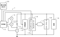
- FIG. 1 is a diagram illustrating a power supply system of a vehicle having a charge control device according to an embodiment of the present invention.
- the charge control apparatus 1 of this embodiment has the control part 10, the voltage sensor 11, the current sensor 12, the temperature sensor 13, and the discharge circuit 15 as main components.
- the control unit 10 is configured to include a calculation unit and a control unit. However, the calculation unit and the control unit may be configured separately.
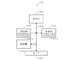
- FIG. 2 is a diagram illustrating a detailed configuration example of the control unit 10.
- the control unit 10 includes a CPU (Central Processing Unit) 10a, a ROM (Read Only Memory) 10b, a RAM (Random Access Memory) 10c, an output unit 10d, a bus 10e, and an I / F (Interface). ) 10f.
- the CPU 10a controls each unit based on the program 10ba stored in the ROM 10b.
- the ROM 10b is configured by a semiconductor memory or the like, and stores a program 10ba or the like.
- the RAM 10c is configured by a semiconductor memory or the like, and stores a parameter 10ca generated when the program 10ba is executed.
- the output unit 10 d supplies a pulse discharge ON / OFF control signal for measuring the internal resistance of the hybrid storage battery 14 to the discharge circuit 15 and supplies a generated voltage control signal to the regulator 16 a of the alternator 16.
- the bus 10e is a signal line group that enables the CPU 10a, the ROM 10b, the RAM 10c, the output unit 10d, and the I / F 10f to exchange data with each other.
- the I / F 10 f converts the signals supplied from the voltage sensor 11, the current sensor 12, the temperature sensor 13, and the vehicle state detection unit 20 into digital signals and takes them in.
- the voltage sensor 11 detects the terminal voltage of the hybrid storage battery 14 and notifies the control unit 10 of it.
- the current sensor 12 detects a charging current and a discharging current flowing through the hybrid storage battery 14 and notifies the control unit 10 of them.
- the temperature sensor 13 detects the hybrid storage battery 14 itself or the ambient environmental temperature and notifies the control unit 10 of it.
- the discharge circuit 15 is configured by, for example, a semiconductor switch that is turned on or off based on a pulse discharge ON / OFF control signal from the control unit 10.
- the discharge circuit 15 has two output terminals connected between the control signal line of the control unit 10 and the ground, and an input terminal connected to the control unit 10. When the pulse discharge ON / OFF control signal is high, the impedance is in a high impedance (off) state, and when the pulse discharge ON / OFF control signal is low, the impedance is in a low impedance (on) state.
- the hybrid storage battery 14 is configured, for example, by mixing a carbon material having conductivity on the surface of the negative electrode active material-filled plate and activated carbon having a capacitor capacity and a pseudo capacitor capacity, and a binder. It is comprised by the lead storage battery provided with the negative electrode plate which provided the coating layer of the carbon mixture as a negative electrode.
- the hybrid storage battery 14 is charged by the alternator 16, drives the starter motor 18 to start the engine 17, and supplies power to the load 19. Further, when the vehicle is decelerated, it is charged with electric power regenerated by the alternator 16.
- the alternator 16 is driven by the rotational force of the engine 17 or the inertial force at the time of deceleration of the vehicle, generates AC power, converts it into DC power by a rectifier circuit, and adjusts the voltage by the regulator 16a.
- Charge In the present invention, by using the hybrid storage battery 14, it can be configured by a single power storage device, and there is no need to mount two or more types of secondary batteries or capacitors. Therefore, compared to a charge control device equipped with two or more kinds of power storage devices, a secondary battery, a voltage converter (for example, a DC / DC converter) and the like can be omitted, and the charge control device can be configured at low cost. .
- the vehicle state detection unit 20 detects vehicle speed, engine speed, accelerator opening, fuel cut signal, brake operation state, and the like, and notifies the control unit 10 of the detected vehicle state.
- the control unit 10 controls the regulator 16a according to the running state of the vehicle detected by the vehicle state detection unit 20 and the state of the hybrid storage battery 14 detected by the voltage sensor 11, the current sensor 12, and the temperature sensor 13. As a result, the power generation voltage of the alternator 16 is adjusted, and the state of charge of the hybrid storage battery 14 is controlled.
- the regulator 16 a controls the power generation voltage of the alternator 16 by controlling a current that flows through an excitation coil (not shown) of the alternator 16 in accordance with a control signal supplied from the control unit 10.
- the voltage generated by the alternator 16 is in a high voltage range when the generated voltage control signal output by the control unit 10 is high (Hi), and the generated voltage output by the control unit 10. When the control signal is low (Lo), the voltage range is low.
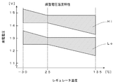
- FIG. 3 is a diagram showing the relationship between the ambient temperature (eg, case temperature) of the regulator 16a and the generated voltage.
- the hatched upper region shows a change in the generated voltage due to the temperature when the generated voltage control signal is high.
- the lower area where hatching is performed shows changes in the generated voltage due to temperature when the generated voltage control signal is low.
- the voltage range of the generated voltage of the alternator 16 varies depending on whether the generated voltage control signal supplied from the control unit 10 to the regulator 16a is high or low.
- the engine 17 is composed of, for example, a reciprocating engine such as a gasoline engine and a diesel engine, or a rotary engine, and is started by a starter motor 18 to drive driving wheels via a transmission to provide propulsive force to the vehicle. Drive to generate power.
- the starter motor 18 is constituted by, for example, a DC motor, and generates a rotational force by the electric power supplied from the hybrid storage battery 14 to start the engine 17.
- the load 19 is constituted by, for example, an electric steering motor, a defogger, an ignition coil, a car audio, a car navigation, and the like, and operates with electric power from the hybrid storage battery 14.
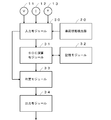
- FIG. 4 is a diagram showing processing modules realized by cooperation of hardware resources such as the CPU 10a and software resources such as the program 10ba when the program 10ba shown in FIG. 3 is executed.
- the processing module includes an input module 30, an SOC calculation module 31, a storage module 32, and an output module 34 as main components.
- the input module 30 inputs signals output from the voltage sensor 11, the current sensor 12, the temperature sensor 13, and the vehicle state detection unit 20, and supplies the signals to the SOC calculation module 31.
- the SOC calculation module 31 calculates the current SOC of the hybrid storage battery 14 based on the voltage, current, and temperature supplied from the input module 30 and supplies the obtained SOC to the determination module 33.
- an equivalent circuit model of the hybrid storage battery 14 is created, and the internal impedance is measured by performing pulsed discharge by the discharge circuit 15, and the parameter of the equivalent circuit model is calculated.
- the SOC is calculated based on the obtained parameters.
- an exponential function equation that approximates the time characteristic of the open circuit voltage of the hybrid storage battery 14 is obtained, the open circuit voltage at that time of the hybrid storage battery 14 is obtained from this exponential function equation, and the SOC is obtained from the obtained open circuit voltage. May be.
- the storage module 32 stores parameters necessary for the SOC calculation module 31 to calculate the SOC, an equivalent circuit model, and the like.
- the determination module 33 outputs control information based on the vehicle state detection unit 20 and the SOC to the output module 34.
- the output module 34 controls the regulator 16a and the like based on the output from the determination module 33.
- the lead storage battery is used at a low SOC, for example, the life of the lead storage battery is shortened due to the occurrence of sulfation, or the starter motor 18 does not rotate and the engine 17 does not start because the capacity is insufficient.
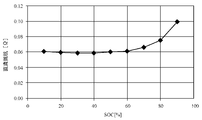
- FIG. 7 is an example showing the relationship between the internal resistance and the SOC during charging of the hybrid storage battery 14.
- the internal resistance is almost constant when the SOC is 60% or less, and the increase rate becomes large when the SOC is 70% or more.
- the SOC that can ensure engine startability varies greatly depending on the vehicle system. Generally, the SOC is set to a value of 50% or more. In the present embodiment, in consideration of these, the hybrid storage battery 14 is used to operate in a low SOC state, and regeneration is efficiently performed by the following control.
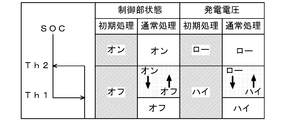
- FIG. 8 is a diagram showing the relationship between the state of the control signal and the generated voltage.
- the processing is different between the initial state immediately after the start of the engine 17 and the other normal state. Therefore, in the following, the operation in the initial state will be described first, and then the operation in the normal state will be described.
- the charging control device 1 executes an initial process.
- the initial process as shown on the left side of the “control unit state” in FIG. 8, when the SOC is equal to or higher than Th2 that is the second threshold value, the generated voltage control signal to the regulator 16 a is controlled to be in an ON state. 8, the power generation voltage of the alternator 16 is in a low state (Lo state in FIG. 3).
- Th2 which is the second threshold value
- the generated voltage control signal is controlled to be in an off state, and the generated voltage of the alternator 16 is in a high state (Hi state in FIG. 3).
- the generated voltage is set to the Hi state and is quickly charged.
- the process shifts to normal processing.
- charge control is executed based on a threshold value having hysteresis. Specifically, as shown at the left end of FIG. 8, the charging control is executed based on two threshold values, Th1 as the first threshold value and Th2 as the second threshold value.
- Th1 as the first threshold value
- Th2 as the second threshold value.
- the generated voltage control signal is controlled to be in the off state during the SOC rising phase.
- the power generation voltage of the alternator 16 is in a high state (Hi state in FIG. 3).
- the generated voltage control signal is controlled to be on, as shown on the right side of “generated voltage” in FIG.
- the generated voltage of the alternator 16 becomes low (the Lo state in FIG. 3).
- Th1 which is the first threshold value
- the generated voltage control signal to the regulator 16a is controlled to be on, and the generated voltage of the alternator 16 is low (see FIG. 3). Lo state).
- Th1 which is the first threshold value
- the generated voltage control signal to the regulator 16a is controlled to be off, and the generated voltage of the alternator 16 is high. (Hi state in FIG. 3).
- control is performed so that the SOC becomes equal to or higher than the second threshold value in the initial process immediately after the start of the engine 17, but when the process shifts to the normal process, the alternator 16 is controlled based on the first threshold value and the second threshold value.
- the generated voltage is controlled.
- the regulator 16a when the vehicle state detection unit 20 detects that the vehicle is in a decelerating state, the regulator 16a is controlled to set the output voltage of the alternator 16 to high. Thereby, since the charging current from the alternator 16 to the hybrid storage battery 14 increases, the kinetic energy of the vehicle can be converted into electric energy and stored in the hybrid storage battery 14.
- 70% and 71% can be used as the first threshold Th1 and the second threshold Th2, respectively.
- the hybrid storage battery 14 is less likely to deteriorate or become unable to start the engine 17 due to insufficient capacity even when the SOC is about 70%. For this reason, as shown in FIG. 5, the hybrid storage battery 14 can be used in a region where the charging efficiency is high. Therefore, not only when the alternator 16 is driven by the engine 17 and the hybrid storage battery 14 is charged, but also when the vehicle is decelerating.
- the hybrid storage battery 14 can be efficiently charged even when the kinetic energy of the vehicle is converted into electric energy by the alternator 16 and charged (when regenerating).
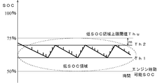
- the SOC of the hybrid storage battery 14 is controlled so as to be within the range of Th1 and Th2, as shown in FIG. More specifically, when the SOC falls below Th1, the output voltage of the alternator 16 is set to Hi and the SOC increases, and the SOC rises above Th2 when the SOC rises. In this case, the output voltage of the alternator 16 is set to Lo and the SOC decreases.
- the SOC of the hybrid storage battery 14 changes, for example, in a sawtooth shape as shown in FIG.
- the hybrid storage battery 14 is charged by the impulse waves shown in the portions of the sawtooth waveform.
- the thresholds Th1 and Th2 are set in a low SOC region where the upper limit is the low SOC region upper limit threshold Thu of the hybrid storage battery 14.
- the low SOC region refers to a low SOC region as compared to the 80 to 100% high SOC region where lead storage is generally operated. By operating in such a low SOC region, it is possible to improve power acceptability during regeneration.
- the low SOC region upper limit threshold value Thu is the time until the charging current flowing through the hybrid storage battery 14 starts to decrease from the maximum generated current after charging starts.
- the charging current is maximized in the range of Th1 to Th2, which is the SOC operating range. Since the time until it starts to decrease from the generated current becomes longer than 5 seconds, most of the regenerative power that lasts about several seconds can be stored in the hybrid storage battery 14 as electric power.
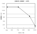
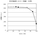
- FIG. 10 An example is shown in FIG. In FIG. 10, the SOC of one secondary battery is adjusted to 50%, 70%, 90%, and 100%, and the secondary battery of each SOC flows to the secondary battery when charged with a constant current of 120A.
- the relationship between current and charging time is shown.
- the maximum voltage of the constant current source is 16.0V, and charging is started from 0 sec in FIG.
- the SOC 90% and 100%, the current greatly decreases immediately after the start of charging.
- the SOC is 70%
- a current of 120 A can flow for about 5 seconds from the start of charging.
- the SOC is 50%
- the set current 120A can be supplied for 180 seconds or more.
- a predetermined charging time from the start of charging is determined, and during this time, the SOC region can be set to the low SOC region by passing the set current.
- the low SOC region upper limit threshold value Thu is, for example, based on the relationship between the internal resistance of the hybrid storage battery 14 (DC resistance shown in FIG. 7) and the SOC, and the internal resistance becomes a predetermined value or less.
- the SOC may be set to the low SOC region upper limit threshold Thu.
- 70% since the increase rate becomes large when the SOC is 70% or more, 70% may be selected as the low SOC region upper limit threshold Thu.
- the charging current when a predetermined time has elapsed from the start of charging is a predetermined value (for example, the current after 5 seconds from the start of charging is 100 A or more or 90% or more of the maximum current of the alternator 16) May be set as the low SOC region upper limit threshold value Thu.
- the maximum SOC (approximately 70% in the example of FIG.
- FIG. 11 is a diagram illustrating an example of change in SOC when the first threshold Th1 is set to 70% and the second threshold Th2 is set to 71%.
- the horizontal axis indicates time (seconds).
- the SOC of the hybrid storage battery 14 becomes 70% or less, which is the first threshold Th ⁇ b> 1 (near 1600 (s) shown in FIG. 11), regardless of the traveling state of the vehicle.
- the output voltage of the alternator 16 is set to a high state, and the hybrid storage battery 14 is rapidly charged so that the SOC of the hybrid storage battery 14 becomes 71% or more.
- the SOC of the hybrid storage battery 14 is controlled to be within the range of 70 to 71%, and when it becomes less than 70%, it can be charged rapidly. Further, when the SOC of the hybrid storage battery 14 is within the range of 70 to 71%, the regeneration can be efficiently performed by setting the regulator 16a to the high state when the vehicle is decelerated.
- FIG. 12 shows measured values when the charge control device of the present invention is mounted on an actual vehicle.
- the vertical axis indicates fuel consumption.
- the actual vehicle A shows a case where the charging control device of the present invention is not installed
- the actual vehicle B shows a case where the charging control device of the present invention is installed.
- the fuel consumption is improved by about 1.36% compared to the case where the charging control device is not mounted.
- the effect of the charge control device of the present invention is obtained.
- step S10 the input module 30 inputs the voltage V, the current I, and the temperature T from the voltage sensor 11, the current sensor 12, and the temperature sensor 13, respectively.
- step S11 the SOC calculation module 31 performs a process of calculating the SOC of the hybrid storage battery 14 based on the voltage V, current I, temperature T input in step S10, and data stored in the storage module 32. .
- adaptive learning using, for example, a Kalman filter is applied to the equivalent circuit model of the hybrid storage battery 14, and the obtained value (for example, OCV (Open Circuit Voltage: open This can be realized by calculating the SOC based on the circuit voltage)).
- OCV Open Circuit Voltage: open This can be realized by calculating the SOC based on the circuit voltage
- step S12 the input module 30 inputs information indicating the state of the vehicle from the vehicle state detection unit 20.
- the vehicle state detection unit 20 detects the vehicle speed, the engine speed, the accelerator opening, the fuel cut signal, the brake operation state, and the like, and supplies them to the input module 30.
- step S13 the determination module 33 refers to the information indicating the vehicle state acquired in step S12, determines whether or not the vehicle is in a deceleration state (a state in which regeneration is possible), and determines that the vehicle is in a deceleration state ( In step S13: Yes, the process proceeds to step S14 where the power generation voltage is set to a high state to perform regenerative charging. In other cases (step S13: No), the process proceeds to step S15. For example, if the vehicle speed is greater than 5 km / h, the accelerator opening is less than 10%, and the fuel cut instruction signal is high, it is determined that the vehicle is decelerating and the process proceeds to step S14. Otherwise, the process proceeds to step S15.
- the fuel cut instruction signal is a signal for instructing to cut (stop) the fuel to be supplied to the engine 17, and indicates that no fuel is supplied to the engine 17 when this signal is turned on.
- the determination criterion described above is an example, and it may be determined whether the vehicle is in a deceleration state based on other information. For example, if the fuel cut instruction signal is in a high state only during deceleration, the determination may be made based only on the fuel cut instruction signal and the vehicle speed. Of course, the determination may be made in consideration of the rotational speed of the engine 17 or the like. Further, even when it is determined that the vehicle is decelerating, regenerative charging may be stopped when any of the conditions is not satisfied. Thereby, it is possible to prevent an unnecessary load from being applied to the engine 17.
- step S14 the output module 34 sets the regulator 16a to a high state. Thereby, the output voltage of the alternator 16 is set to a high state, and charging (regenerative charging) of the hybrid storage battery 14 by kinetic energy at the time of deceleration of the vehicle is executed.
- step S14 the process ends.
- step S17 the output module 34 sets the regulator 16a to a high state. As a result, the output voltage of the alternator 16 is set to a high state, and the hybrid storage battery 14 is charged by the driving force of the engine 17.
- step S19 the process proceeds to step S19.
- step S18 the output module 34 sets the regulator 16a to a low state. As a result, the output voltage of the alternator 16 is set to a low state.
- step S21 the output module 34 sets the regulator 16a to a low state. As a result, the output voltage of the alternator 16 is set to a low state.
- step S23 the output module 34 sets the regulator 16a to a high state. Thereby, the output voltage of the alternator 16 is set to a high state.
- step S24 the output module 34 sets the previous power generation voltage as the power generation voltage of the regulator 16a. Specifically, when the previous power generation voltage is low, it is set to low, and when it is high, it is set to high. As a result, when the SOC exists in the range of Th1 ⁇ SOC ⁇ Th2, the previous value is used. Therefore, as shown in FIG. 8, the output voltage of the alternator 16 is the same in the rising phase or the falling phase. Maintained.
- step S25 the determination module 33 sets the current power generation voltage as the previous power generation voltage. Specifically, if the current power generation voltage is low, it is set to low, and if it is high, it is set to high.
- the SOC in the first process after the engine 17 is started, the SOC is referred to, and the voltage of the alternator 16 is set to a high state so that the SOC of the hybrid storage battery 14 is 71% or more. Is done.
- the generated voltage when the SOC is 71% or more, the generated voltage is set to low, when the SOC is 70% or less, it is set to high, and when it is greater than 70% and less than 71%. The previous generated voltage is maintained. Thereby, the voltage setting shown in FIG. 8 becomes possible. Moreover, chattering can be prevented from occurring by providing two threshold values and performing control based on hysteresis.
- the power generation voltage is set to high and regeneration is performed, so that fuel consumption can be improved.
- the charge control device 1 includes the voltage sensor 11, the current sensor 12, and the temperature sensor 13, and the SOC is calculated in real time.
- the SOC is calculated in real time.
- Th1 and Th2 it is known from actual measurement results that the smaller the difference between Th1 and Th2, the better the fuel consumption. Therefore, it is desirable to set the difference between Th1 and Th2 as small as possible.
- the interval between Th1 and Th2 is less than 10%, preferably less than several percent.
- Th1 and Th2 are fixed values. For example, these values may be rewritable. By setting it as such a structure, you may enable it to adjust these values suitably according to the kind and use purpose of the hybrid storage battery 14, for example. Moreover, the capacity
- the second threshold value in the normal process is used as the threshold value in the initial process.
- the threshold value in the initial process may be different from the second threshold value. For example, by using a value larger than the second threshold, it is possible to rapidly charge up to a certain SOC in the initial process.
- the threshold value for the initial process to the second threshold value, the transition from the initial process to the normal process can be performed smoothly.
- the alternator 16 can set two types of voltages, high and low.
- an alternator that can output a desired voltage according to the generated voltage signal is used. You may make it use.
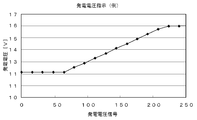
- the generated voltage signal is in the range of 0 to about 60 and is a little over 11V, and in the range of 60 to 220, the voltage rises according to the value of the signal.
- an alternator when used, for example, it can be set to 12.0 ⁇ 0.5 V when the vehicle is accelerating or traveling at a constant speed, and can be set to 15.0 V or more when the vehicle is decelerating.
- the generated voltage is set to 12.0 ⁇ 0.5V
- the generated voltage is set to 14.5V.
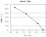
- FIG. 15 shows the relationship between the SOC and voltage when the vehicle is traveling at a constant speed or accelerating.
- the alternator voltage indicated by the broken line is set higher than the voltage of the hybrid storage battery, and when the SOC is greater than 60%, the voltage of the hybrid storage battery is It is set to be higher than the voltage of the alternator. At this time, the voltage difference between the hybrid storage battery and the alternator is set to be constant.
- FIG. 16 shows the relationship between SOC and voltage during deceleration. In the example of FIG.
- the voltage difference between the hybrid storage battery and the alternator is set so as to decrease as the SOC value increases. More specifically, the generated voltage of the alternator may be controlled so that the voltage difference between the reference voltage and the alternator indicated by the alternate long and short dash line is equal to the voltage difference between the reference voltage and the hybrid storage battery.
- the difference voltage between the terminal voltage of the hybrid storage battery 14 and the reference voltage can be obtained, and the output voltage of the alternator 16 can be controlled to be equal to the voltage obtained by adding the difference voltage to the reference voltage.
- the electric power is supplied from the hybrid storage battery 14 to the load 19 by setting the voltage of the alternator 16 lower than the terminal voltage of the hybrid storage battery 14. May be reliably supplied.
- the hybrid storage battery 14 since the hybrid storage battery 14 has a voltage lower than that of a normal lead storage battery, such control is effective.
- the detection value of the temperature sensor 13 is not described in detail. However, since the characteristics of the hybrid storage battery 14 vary depending on the ambient temperature, the SOC calculated based on the output of the temperature sensor 13 is calculated. You may make it correct
- the SOC range and the reference value are fixed values. However, for example, these values may be changed according to the state of the hybrid storage battery 14 (for example, the deterioration state). Specifically, when the hybrid storage battery 14 is deteriorated, the capacity is reduced. Therefore, in order to obtain the same capacity as in the new case, it is necessary to set a wide SOC range.
- FIG. 17 is a diagram showing the relationship between the current value at 5 seconds from the start of charging and the SOC when a lead storage battery different from FIG. 6 is charged with a charging current of 100 A.
- FIG. 18 is a diagram showing the relationship between the charge amount (As) for 5 seconds from the start of charging and the SOC when the same lead storage battery as in FIG. 17 is charged with a charging current of 100 A.
- the SOC exceeds 80%, the charging current and the charging amount decrease. Therefore, in the lead storage battery shown in FIGS.
- 80 to 85% can be selected as the low SOC region upper limit threshold value Thu.
- the low SOC region upper limit threshold Thu it is desirable to set the low SOC region upper limit threshold Thu to a value of about 80 to 85% or smaller.
- the margin m shown in FIG. 9 can be set to a value of about several percent, for example. Of course, the value may be larger than this, or may be smaller than this including 0.
- a plurality of power storage devices for example, lithium batteries, nickel batteries, nickel metal hydride batteries, capacitors, etc.
- a hybrid storage battery for example, lithium batteries, nickel batteries, nickel metal hydride batteries, capacitors, etc.
- SYMBOLS 1 Charge control apparatus 10 Control part (calculation means, control means) 10a CPU 10b ROM 10c RAM 10d communication unit 10e bus 10f I / F 11 Voltage sensor (calculation means) 12 Current sensor (calculation means) 13 Temperature sensor (calculation means) 14 Hybrid storage battery (secondary battery) DESCRIPTION OF SYMBOLS 15 Discharge circuit 16 Alternator 16a Regulator 17 Engine 18 Starter motor 19 Load 20 Vehicle state detection part (detection means)
Abstract
【課題】二次電池の充電制御および回生制御を効率よく行うこと。 【解決手段】二次電池の充電状態を算出する算出手段(電圧センサ11、電流センサ12、制御部10)と、車両の走行状態を検出する検出手段(車両状態検出部20)と、減速状態であることが検出された場合にはオルタネータが発生する電圧を二次電池の端子電圧よりも高く設定することで回生電力によって充電する制御を行い、車両が減速状態以外であることが検出された場合であって、充電率が所定の第2閾値よりも大きい場合には、オルタネータが発生する電圧を二次電池の端子電圧よりも低く設定し、充電率が所定の第1閾値よりも小さい場合には、オルタネータが発生する電圧を二次電池の端子電圧よりも高く設定する制御を行う制御手段(制御部10)と、を有し、第2閾値は第1閾値よりも大きく、第1および第2閾値は低SOC領域にあることを特徴とする。
Description
本発明は、充電制御装置および充電制御方法に関するものである。
自動車等の車両では、エンジンの動力でオルタネータ(発電機)を回転させ、発生した電力で二次電池を充電し、二次電池に蓄えられた電力を用いて各種の負荷(例えば、電動ステアリング)を駆動する。
ところで、近年、車両が減速する際に、オルタネータから発生する電力によって二次電池を充電することで、車両の運動エネルギを電気エネルギに変換して二次電池に蓄える方法が提案されている。
例えば、特許文献1には、車両の減速時にオルタネータの電圧を高くすることで二次電池に電力を回生する技術が開示され、また、特許文献2には、充電電流によって二次電池の充電量(SOC)を推定し、推定結果に基づいて回生を行う技術が開示されている。また、特許文献3,4には、2つの蓄電装置を用いることで、回生を効率よく行う技術が開示されている。
ところで、二次電池は、充電率が低いほど充電電流の受け入れ率(充電効率)が高いため、ある程度低い充電率で運用することが望ましい。しかしながら、従来技術の充電制御では、二次電池の充電率を電流積算値から求めるため、誤差の累積による影響を少なくするために、一度満充電状態にしてから充電率を推定する。このため、満充電にするための電力が無駄になるとともに、充電率が高いほど受け入れ率が低い状態で運用することになるため、回生の効率が低くなるという問題点がある。また、蓄電装置を2つ用いる方法では、蓄電装置と充電のための機器が2倍必要になることからコストが高くつくとともに、電圧が異なる2つの蓄電装置から給電するために、例えば、DC/DCコンバータが必要になるため、さらにコストが高くつくという問題点がある。
そこで、本発明は二次電池の回生制御および充電制御を効率よく行うことが可能な充電制御装置および充電制御方法を提供することを目的としている。
上記課題を解決するために、本発明は、車両に搭載されている二次電池の充電状態を制御する充電制御装置において、前記二次電池の端子電圧および充放電電流に基づいて当該二次電池のその時点における充電状態を算出する算出手段と、前記車両の走行状態を検出する検出手段と、前記検出手段によって前記車両が減速状態であることが検出された場合には、オルタネータが発生する電圧を前記二次電池の端子電圧よりも高く設定することで回生電力によって前記二次電池を充電する制御を行い、前記検出手段によって前記車両が減速状態以外であることが検出された場合であって、前記算出手段によって算出された前記二次電池の充電率が所定の第2閾値よりも大きい場合には、前記オルタネータが発生する電圧を前記二次電池の端子電圧よりも低く設定し、前記算出手段によって算出された前記二次電池の充電率が所定の第1閾値よりも小さい場合には、前記オルタネータが発生する電圧を前記二次電池の端子電圧よりも高く設定する制御を行う制御手段と、を有し、前記第2閾値は前記第1閾値よりも大きく、前記第1閾値および第2閾値は低SOC領域にあることを特徴とする。
このような構成によれば、二次電池の回生制御および充電制御を効率よく行うことが可能となる。
このような構成によれば、二次電池の回生制御および充電制御を効率よく行うことが可能となる。
また、本発明の一側面は、前記低SOC領域は、前記二次電池をオルタネータの出力電圧の範囲内で、オルタネータの最大発電電流で充電した場合に、充電開始から、前記二次電池に流れる充電電流が前記最大発電電流から低下し始めるまでの時間に基づいて、前記時間が所定の値以上となるように設定されていることを特徴とする。
このような構成によれば、低SOC領域で運用することで、二次電池の充電受け入れ性を高め、燃費性能を向上させることができる。
このような構成によれば、低SOC領域で運用することで、二次電池の充電受け入れ性を高め、燃費性能を向上させることができる。
また、本発明の一側面は、前記低SOC領域は、前記二次電池の内部抵抗と前記充電率の関係に基づき、前記内部抵抗が所定の値以下となるように設定されていることを特徴とする。
このような構成によれば、低SOC領域で運用することで、二次電池の充電受け入れ性を高め、燃費性能を向上させることができる。
このような構成によれば、低SOC領域で運用することで、二次電池の充電受け入れ性を高め、燃費性能を向上させることができる。
また、本発明の一側面は、前記低SOC領域は、充電開始から所定の時間が経過した際に、前記二次電池に流れる充電電流が所定の値以上となる領域であることを特徴とする。
このような構成によれば、低SOC領域で運用することで、二次電池の充電受け入れ性を高め、燃費性能を向上させることができる。
このような構成によれば、低SOC領域で運用することで、二次電池の充電受け入れ性を高め、燃費性能を向上させることができる。
また、本発明の一側面は、前記低SOC領域は、充電開始から所定の時間が経過するまでにおける前記二次電池の充電量が所定の値以上となる領域であることを特徴とする。
このような構成によれば、低SOC領域で運用することで、二次電池の充電受け入れ性を高め、燃費性能を向上させることができる。
このような構成によれば、低SOC領域で運用することで、二次電池の充電受け入れ性を高め、燃費性能を向上させることができる。
また、本発明の一側面は、前記二次電池は、電気化学反応を利用して電力を蓄積する二次電池と、電荷吸着現象を利用したキャパシタとが複合形成されたハイブリッド型の二次電池であることを特徴とする。
このような構成によれば、二次電池を低い充電率で運用することで、充電効率を高め、燃費を改善することができる。
このような構成によれば、二次電池を低い充電率で運用することで、充電効率を高め、燃費を改善することができる。
また、本発明の一側面は、前記算出手段は、放電回路によってパルス状の放電を行うことで、内部インピーダンスを測定し、前記二次電池の等価回路モデルのパラメータに基づいて前記充電率を算出することを特徴とする。
このような構成によれば、二次電池の充電率を精度よく求め、この精度よく求めた充電率に基づいて制御を確実に行うことができる。
このような構成によれば、二次電池の充電率を精度よく求め、この精度よく求めた充電率に基づいて制御を確実に行うことができる。
また、本発明の一側面は、前記車両に搭載され、前記回生電力を蓄電する蓄電装置は、前記二次電池のみであることを特徴とする。
このような構成によれば、複数の蓄電装置を搭載する場合に比較して、製造コストを低減するとともに、メンテナンスを簡略化することができる。
このような構成によれば、複数の蓄電装置を搭載する場合に比較して、製造コストを低減するとともに、メンテナンスを簡略化することができる。
また、本発明の一側面は、前記制御手段は、前記第1閾値および第2閾値のそれぞれの値を前記二次電池の状態に応じて変更することを特徴とする。
このような構成によれば、2つの閾値のそれぞれの値を二次電池の状態に応じて変更することで、例えば、二次電池の劣化に応じて適切な値に変更することで、劣化によらず高い燃費を維持することができる。
このような構成によれば、2つの閾値のそれぞれの値を二次電池の状態に応じて変更することで、例えば、二次電池の劣化に応じて適切な値に変更することで、劣化によらず高い燃費を維持することができる。
また、本発明の一側面は、前記車両が減速時以外である場合に、前記オルタネータが発生する電圧を前記二次電池の端子電圧よりも低く設定することで、前記二次電池から負荷に給電することを特徴とする。
このような構成によれば、例えば、加速時にオルタネータからの給電を停止することで、エンジンの負担を軽減することで燃費を改善することができる。
このような構成によれば、例えば、加速時にオルタネータからの給電を停止することで、エンジンの負担を軽減することで燃費を改善することができる。
また、本発明の一側面は、前記オルタネータは、発生する電圧の範囲として、第1電圧範囲と、第1電圧範囲よりも電圧が低い第2電圧範囲のいずれかを選択可能であり、前記制御手段は、前記二次電池の状態と前記車両の状態に応じて前記第1または第2電圧範囲を選択することを特徴とする。
このような構成によれば、2種類の電圧範囲を選択することで、回生による充電を簡単にしかも効率よく行うことができる。
このような構成によれば、2種類の電圧範囲を選択することで、回生による充電を簡単にしかも効率よく行うことができる。
また、本発明の一側面は、前記オルタネータは、指定された電圧を出力可能であり、前記制御手段は、前記二次電池の状態と前記車両の状態に応じた電圧を前記オルタネータに出力させることを特徴とする。
このような構成によれば、電圧を細かく制御することで、回生による充電を一層効率よく行うことができる。
このような構成によれば、電圧を細かく制御することで、回生による充電を一層効率よく行うことができる。
また、本発明の一側面は、前記制御手段は、車両の走行状態および前記二次電池の充電率に応じて、前記二次電池の端子電圧と前記オルタネータが発生する電圧との差が所定の所望の値となるように前記オルタネータを制御することを特徴とする。
このような構成によれば、定電流によって二次電池を充電することが可能になる。
このような構成によれば、定電流によって二次電池を充電することが可能になる。
また、本発明の一側面は、前記制御手段は、前記車両の減速時には、前記二次電池の端子電圧と基準電圧との差の電圧を求め、この差の電圧を前記基準電圧に加算した電圧が、オルタネータが発生する電圧となるように前記オルタネータを制御することを特徴とする。
このような構成によれば、充電率が低い場合にはオルタネータの電圧を高く設定して、急速に充電することが可能になる。
このような構成によれば、充電率が低い場合にはオルタネータの電圧を高く設定して、急速に充電することが可能になる。
また、本発明の一側面は、前記制御手段は、車速が所定の速度以上であり、かつ、燃料カット指示信号によって燃料カットが指示されている場合には、前記車両が減速状態であると判定することを特徴とする。
このような構成によれば、減速状態であることを簡易に検出することが可能になる。
このような構成によれば、減速状態であることを簡易に検出することが可能になる。
また、本発明の一側面は、前記車速と前記燃料カット指示信号に加えて、前記車両のアクセル開度が所定の開度以下である場合には、前記車両が減速状態であると判定することを特徴とする。
このような構成によれば、減速状態であることを確実に検出することが可能になる。
このような構成によれば、減速状態であることを確実に検出することが可能になる。
また、本発明の一側面は、前記車速、前記燃料カット指示信号、および、アクセル開度のいずれかが条件を満たさなくなった場合には、回生動作を停止することを特徴とする。
このような構成によれば、減速状態以外で充電され、エンジンに不要な負担がかかることを防止できる。
このような構成によれば、減速状態以外で充電され、エンジンに不要な負担がかかることを防止できる。
また、本発明の一側面は、車両に搭載されている二次電池の充電状態を制御する充電制御方法において、前記二次電池の端子電圧および充放電電流に基づいて当該二次電池のその時点における充電状態を算出する算出ステップと、前記車両の走行状態を検出する検出ステップと、前記検出ステップにおいて前記車両が減速状態であることが検出された場合には、オルタネータが発生する電圧を前記二次電池の端子電圧よりも高く設定することで回生電力によって前記二次電池を充電する制御を行い、前記検出ステップにおいて前記車両が減速状態以外であることが検出された場合であって、前記算出ステップによって算出された前記二次電池の充電率が所定の第2閾値よりも大きい場合には、前記オルタネータが発生する電圧を前記二次電池の端子電圧よりも低く設定し、前記算出ステップにおいて算出された前記二次電池の充電率が所定の第1閾値よりも小さい場合には、前記オルタネータが発生する電圧を前記二次電池の端子電圧よりも高く設定する制御を行う制御ステップと、を有し、前記第2閾値は前記第1閾値よりも大きく、前記第1閾値および第2閾値は低SOC領域にあることを特徴とする。
このような方法によれば、二次電池の回生制御および充電制御を効率よく行うことが可能となる。
このような方法によれば、二次電池の回生制御および充電制御を効率よく行うことが可能となる。
本発明によれば、二次電池の回生制御および充電制御を効率よく行うことが可能な充電制御装置および充電制御方法を提供することが可能となる。
次に、本発明の実施形態について説明する。
(A)実施形態の構成の説明
図1は、本発明の実施形態に係る充電制御装置を有する車両の電源系統を示す図である。なお、本実施形態の充電制御装置1は、制御部10、電圧センサ11、電流センサ12、温度センサ13、および、放電回路15を主要な構成要素としている。本実施形態においては、制御部10が算出手段、制御手段を含むように構成しているが、算出手段、制御手段を別体として構成することも可能である。
図1は、本発明の実施形態に係る充電制御装置を有する車両の電源系統を示す図である。なお、本実施形態の充電制御装置1は、制御部10、電圧センサ11、電流センサ12、温度センサ13、および、放電回路15を主要な構成要素としている。本実施形態においては、制御部10が算出手段、制御手段を含むように構成しているが、算出手段、制御手段を別体として構成することも可能である。
ここで、制御部10は、ハイブリッド蓄電池14のSOC(State of Charge)(充電率)を算出し、算出したSOCに基づいてレギュレータ16aを制御する。図2は、制御部10の詳細な構成例を示す図である。この図に示すように、制御部10は、CPU(Central Processing Unit)10a、ROM(Read Only Memory)10b、RAM(Random Access Memory)10c、出力部10d、バス10e、および、I/F(Interface)10fを有している。ここで、CPU10aは、ROM10bに格納されているプログラム10baに基づいて各部を制御する。ROM10bは、半導体メモリ等によって構成され、プログラム10ba等を格納している。RAM10cは、半導体メモリ等によって構成され、プログラム10baを実行する際に生成されるパラメータ10caを格納する。出力部10dは、放電回路15に対してハイブリッド蓄電池14の内部抵抗を測定するためのパルス放電ON/OFF制御信号を供給するとともに、オルタネータ16のレギュレータ16aに対して発電電圧制御信号を供給する。バス10eは、CPU10a、ROM10b、RAM10c、出力部10d、および、I/F10fを相互にこれらの間でデータの授受を可能とするための信号線群である。I/F10fは、電圧センサ11、電流センサ12、温度センサ13、および、車両状態検出部20から供給される信号をデジタル信号に変換して取り込む。
電圧センサ11は、ハイブリッド蓄電池14の端子電圧を検出し、制御部10に通知する。電流センサ12は、ハイブリッド蓄電池14に流れる充電電流および放電電流を検出し、制御部10に通知する。温度センサ13は、ハイブリッド蓄電池14自体または周囲の環境温度を検出し、制御部10に通知する。放電回路15は、例えば、制御部10からのパルス放電ON/OFF制御信号に基づいてオンまたはオフの状態となる半導体スイッチによって構成される。放電回路15は、制御部10の制御信号線とグランドとの間に2つの出力端子が接続され、入力端子が制御部10に接続される。そして、パルス放電ON/OFF制御信号がハイの場合にはハイインピーダンス(オフ)状態となり、パルス放電ON/OFF制御信号がローの場合にはローインピーダンス(オン)状態となる。
ハイブリッド蓄電池14は、例えば、負極活物質充填板の表面に導電性を有するカーボン材料とキャパシタ容量および擬似キャパシタ容量を有する活性炭とから成る2種類のカーボン材料と、結着剤を混合して構成されるカーボン合剤の被覆層を設けた負極板を負極として備える鉛蓄電池によって構成される。このハイブリッド蓄電池14は、オルタネータ16によって充電され、スタータモータ18を駆動してエンジン17を始動するとともに、負荷19に電力を供給する。また、車両の減速時には、オルタネータ16によって回生される電力によって充電される。オルタネータ16は、エンジン17の回転力または車両の減速時の慣性力によって駆動され、交流電力を発生して整流回路によって直流電力に変換し、レギュレータ16aによって電圧が調整された後、ハイブリッド蓄電池14を充電する。本発明では、ハイブリッド蓄電池14を用いることで、単一の蓄電装置で構成することができ、2種以上の二次電池やキャパシタを搭載する必要がない。そのため、2種以上の蓄電装置を搭載する充電制御装置に比べ、二次電池や電圧変換器(例えば、DC/DCコンバータ)等を省くことができ、充電制御装置を安価に構成することができる。
車両状態検出部20は、車速、エンジンの回転数、アクセルの開度、燃料カット信号、ブレーキの操作状態等を検出し、制御部10に通知する。制御部10は、車両状態検出部20によって検出される車両の走行状態と、電圧センサ11、電流センサ12、および、温度センサ13によって検出されるハイブリッド蓄電池14の状態に応じて、レギュレータ16aを制御することでオルタネータ16の発電電圧を調整し、ハイブリッド蓄電池14の充電状態を制御する。レギュレータ16aは、制御部10から供給される制御信号に応じて、オルタネータ16の図示しない励磁コイルに流す電流を制御することで、オルタネータ16の発電電圧を制御する。なお、本実施形態では、オルタネータ16が発電する電圧は、制御部10が出力する発電電圧制御信号がハイ(Hi)の場合には高い電圧の範囲となり、また、制御部10が出力する発電電圧制御信号がロー(Lo)の場合には低い電圧の範囲となる。
図3は、レギュレータ16aの周囲温度(例えば、ケース温度)と、発電電圧との関係を示す図である。ここで、ハッチングが施された上側の領域は発電電圧制御信号がハイの場合における発電電圧の温度による変化を示している。また、ハッチングが施された下側の領域は発電電圧制御信号がローの場合における発電電圧の温度による変化を示している。このように、オルタネータ16の発電電圧は、制御部10からレギュレータ16aに供給される発電電圧制御信号がハイかローかによって電圧の範囲が異なる。
エンジン17は、例えば、ガソリンエンジンおよびディーゼルエンジン等のレシプロエンジンまたはロータリーエンジン等によって構成され、スタータモータ18によって始動され、トランスミッションを介して駆動輪を駆動し車両に推進力を与えるとともに、オルタネータ16を駆動して電力を発生させる。スタータモータ18は、例えば、直流電動機によって構成され、ハイブリッド蓄電池14から供給される電力によって回転力を発生し、エンジン17を始動する。負荷19は、例えば、電動ステアリングモータ、デフォッガ、イグニッションコイル、カーオーディオ、および、カーナビゲーション等によって構成され、ハイブリッド蓄電池14からの電力によって動作する。
図4は、図3に示すプログラム10baが実行された場合に、CPU10a等のハードウエア資源と、プログラム10ba等のソフトウエア資源とが協働することにより実現される処理モジュールを示す図である。この例では、処理モジュールは、入力モジュール30、SOC演算モジュール31、記憶モジュール32、および、出力モジュール34を主要な構成要素としている。ここで、入力モジュール30は、電圧センサ11、電流センサ12、温度センサ13、および、車両状態検出部20から出力される信号を入力し、SOC演算モジュール31に供給する。SOC演算モジュール31は、入力モジュール30から供給される電圧、電流、および、温度に基づいてハイブリッド蓄電池14のその時点におけるSOCを演算し、得られたSOCを判定モジュール33に供給する。なお、SOCを演算する方法としては、例えば、ハイブリッド蓄電池14の等価回路モデルを作成し、放電回路15によってパルス状の放電を行うことで、内部インピーダンスを測定し、当該等価回路モデルのパラメータに対して、例えば、カルマンフィルタ等を用いて適用学習を実行し、得られたパラメータに基づいてSOCを算出する方法がある。また、ハイブリッド蓄電池14の開回路電圧の時間特性を近似する指数関数式を求め、この指数関数式からハイブリッド蓄電池14のその時点における開回路電圧を求め、求めた開回路電圧からSOCを求めるようにしてもよい。もちろん、これら以外の方法によってSOCを算出することも可能である。記憶モジュール32は、SOC演算モジュール31がSOCを算出する際に必要なパラメータおよび等価回路モデル等を記憶する。判定モジュール33は、車両状態検出部20と、SOCとに基づく制御情報を出力モジュール34に対して出力する。出力モジュール34は、判定モジュール33からの出力に基づいて、レギュレータ16a等を制御する。
(B)実施形態の動作の概略の説明
つぎに、本実施形態の動作の概要を説明する。本発明の実施形態では、車両の減速時において、レギュレータ16aを制御し、オルタネータ16の発電電圧を上昇させることによりハイブリッド蓄電池14への充電電流を増加させ、その結果として、車両の運動エネルギを電気エネルギに変換してハイブリッド蓄電池14に蓄積する。ところで、鉛蓄電池の充電量とSOCの関係は図5に示すようになる。ここで、充電量とは10秒間充電した場合の蓄積される電荷量(充電受け入れ値)を示す。図5に示すように、鉛蓄電池のSOCが増加すると、10秒間充電した場合の蓄積される電荷量(充電受け入れ値)が低下する。このため、効率よく充電するためには、できるだけ低いSOCで運用することが望ましい。しかし、鉛蓄電池を低いSOCで使用すると、例えば、サルフェーションの発生により鉛蓄電池の寿命が短くなったり、容量が足らないためにスタータモータ18が回転せず、エンジン17が始動しなかったりする。
つぎに、本実施形態の動作の概要を説明する。本発明の実施形態では、車両の減速時において、レギュレータ16aを制御し、オルタネータ16の発電電圧を上昇させることによりハイブリッド蓄電池14への充電電流を増加させ、その結果として、車両の運動エネルギを電気エネルギに変換してハイブリッド蓄電池14に蓄積する。ところで、鉛蓄電池の充電量とSOCの関係は図5に示すようになる。ここで、充電量とは10秒間充電した場合の蓄積される電荷量(充電受け入れ値)を示す。図5に示すように、鉛蓄電池のSOCが増加すると、10秒間充電した場合の蓄積される電荷量(充電受け入れ値)が低下する。このため、効率よく充電するためには、できるだけ低いSOCで運用することが望ましい。しかし、鉛蓄電池を低いSOCで使用すると、例えば、サルフェーションの発生により鉛蓄電池の寿命が短くなったり、容量が足らないためにスタータモータ18が回転せず、エンジン17が始動しなかったりする。
また、実際の車両において、回生発電された電力を効率よく充電するためには、オルタネータの発電電流を考慮する必要がある。例えば、オルタネータの発電電圧が14.5V、発電電流が120A、充電開始から5秒後の充電電流とSOCの関係を図6に示す。この場合には、SOCを72%以上とすると充電電流が減少する。そのため、SOCを72%以下に設定することにより効率よく充電することが可能となる。回生発電された電力を効率よく充電するためには、二次電池の充電特性から、SOCを設定することも可能である。図7は、ハイブリッド蓄電池14の充電時の内部抵抗とSOCの関係を示す例である。内部抵抗はSOCが60%以下ではほぼ一定であり、70%以上で増加率が大きくなる。内部抵抗が低い、低SOCの領域で二次電池を使用することにより、回生発電による電力を効率よく充電することが可能となる。SOCが低い状態で運用するにあたっては、エンジンの始動性を考慮する必要がある。エンジンの始動性が確保できるSOCは車両のシステムによって大きく異なる。一般的にはSOCが50%以上の値に設定される。本実施形態ではこれらを考慮し、低いSOCの状態で運用するためにハイブリッド蓄電池14を使用するとともに、以下に示すような制御によって、回生を効率良く行うようにしている。
図8は制御信号の状態と発電電圧の関係を示す図である。本実施形態では、図8に示すように、エンジン17の始動直後の初期状態とそれ以外の通常状態とでは処理が異なっている。そこで、以下では、まず、初期状態の動作について説明し、つぎに、通常状態の動作について説明する。
エンジン17が始動された直後の初期状態においては、充電制御装置1は、初期処理を実行する。初期処理では、図8の「制御部状態」の左側に示すように、SOCが第2閾値であるTh2以上である場合にはレギュレータ16aへの発電電圧制御信号がオンの状態に制御され、図8の「発電電圧」の左側に示すように、オルタネータ16の発電電圧がローの状態(図3のLoの状態)になる。一方、SOCが第2閾値であるTh2未満である場合には発電電圧制御信号がオフの状態に制御され、オルタネータ16の発電電圧がハイの状態(図3のHiの状態)になる。換言すると、エンジン17を始動した直後の初期状態では、ハイブリッド蓄電池14のSOCが第2閾値Th2未満の場合には発電電圧がHiの状態とされて速やかに充電がされる。
エンジン17が始動されてから一定時間が経過すると通常処理に移行する。通常処理では、ヒステリシスを有する閾値に基づいて充電制御が実行される。具体的には、図8の左端に示すように、第1閾値であるTh1および第2閾値であるTh2の2つの閾値に基づいて充電制御が実行される。通常処理では、図8の「制御部状態」の右側に示すように、SOCの上昇局面において、SOCが第2閾値であるTh2未満である場合には発電電圧制御信号がオフの状態に制御され、図8の「発電電圧」の右側に示すように、オルタネータ16の発電電圧がハイの状態(図3のHiの状態)になる。また、同じく、SOCの上昇局面において、SOCが第2閾値であるTh2以上となった場合には発電電圧制御信号がオンの状態に制御され、図8の「発電電圧」の右側に示すように、オルタネータ16の発電電圧がローの状態(図3のLoの状態)になる。一方、SOCの下降局面において、SOCが第1閾値であるTh1より大きい場合にはレギュレータ16aへの発電電圧制御信号がオンの状態に制御され、オルタネータ16の発電電圧がローの状態(図3のLoの状態)になる。また、同じく、SOCの下降局面において、SOCが第1閾値であるTh1以下になった場合にはレギュレータ16aへの発電電圧制御信号がオフの状態に制御され、オルタネータ16の発電電圧がハイの状態(図3のHiの状態)になる。
以上の制御により、エンジン17の始動直後の初期処理では、SOCが第2閾値以上になるように制御がなされるが、通常処理に移行すると、第1閾値および第2閾値に基づいてオルタネータ16の発電電圧が制御される。
また、本実施形態では、車両状態検出部20によって、車両が減速状態であることが検出された場合には、レギュレータ16aを制御して、オルタネータ16の出力電圧をハイに設定する。これにより、オルタネータ16からハイブリッド蓄電池14への充電電流が増加することから、車両の運動エネルギを電気エネルギに変換してハイブリッド蓄電池14に蓄積することができる。
また、本発明の実施形態では第1閾値Th1、第2閾値Th2として、例えば、70%,71%をそれぞれ用いることができる。ハイブリッド蓄電池14は、SOC=70%程度の運用においても、劣化が進んだり、容量不足によってエンジン17が始動できなくなったりすることが少ない。このため、図5に示すように、充電効率が高い領域においてハイブリッド蓄電池14を用いることができるので、エンジン17によってオルタネータ16を駆動し、ハイブリッド蓄電池14を充電する場合のみならず、車両の減速時において、車両の運動エネルギをオルタネータ16によって電気エネルギに変換して充電する場合(回生する場合)も効率良くハイブリッド蓄電池14を充電することができる。
すなわち、本実施形態では、ハイブリッド蓄電池14のSOCは、図9に示すように、Th1とTh2の範囲内に収まるように制御される。より詳細には、SOCの下降局面において、SOCがTh1以下となった場合にはオルタネータ16の出力電圧がHiに設定されてSOCが増加し、SOCの上昇局面において、SOCがTh2以上となった場合にはオルタネータ16の出力電圧がLoに設定されてSOCが減少する。このような動作により、ハイブリッド蓄電池14のSOCは、図9に示すように、例えば、鋸歯状に変化する。また、回生が実行された場合には、鋸歯状の波形の所々に示すインパルス波によって、ハイブリッド蓄電池14が充電される。なお、閾値Th1,Th2は、ハイブリッド蓄電池14の低SOC領域上限閾値Thuを上限とする低SOC領域内に設定されている。ここで、低SOC領域とは、鉛蓄電が一般的に運用される80~100%の高SOC領域に比較して低いSOCの領域をいう。このように低SOC領域で運用することで、回生時における電力の受け入れ性を高めることができる。
なお、低SOC領域上限閾値Thuは、例えば、オルタネータ16の最大発電電流でハイブリッド蓄電池14を充電した場合に、充電開始後、ハイブリッド蓄電池14に流れる充電電流が、最大発電電流から低下し始めるまでの時間に基づいて設定することができる。より詳細には、車両の減速による回生充電の継続時間は、大半が10秒未満であり、また、数秒程度の頻度が最も高いことから、一例として、充電開始後、ハイブリッド蓄電池14に流れる充電電流が最大発電電流から低下し始めるまでの時間が「5秒」の場合を低SOC領域上限閾値Thuとして設定することができる。このように、5秒の場合を低SOC領域上限閾値Thuとして設定し、所定のマージンmを隔てたTh2を設定することで、SOCの運用範囲であるTh1~Th2の範囲では、充電電流が最大発電電流から低下し始めるまでの時間は5秒よりも大きくなることから、数秒程度継続する回生電力の殆どをハイブリッド蓄電池14に電力として蓄えることができる。
一例を図10に示す。図10は、一つの二次電池のSOCを50%、70%、90%、および、100%に調整し、各SOCの二次電池を120Aの定電流で充電した際の二次電池に流れる電流と充電時間との関係を示している。定電流源の最大電圧は16.0Vであり、図10において、0secから充電を開始している。SOCが90%および100%の場合は、充電開始直後から電流は大きく低下する。SOCが70%の場合は、充電開始から約5secの間は120Aの電流を流すことができる。また、SOCが50%の場合は180sec以上、設定電流120Aを流すことができる。このように、SOCを低く設定することにより、効率的に二次電池を充電することが可能になる。この場合、充電開始からの所定の充電時間を定め、その間、設定電流を流すことがSOCの領域を低SOC領域とすることができる。
なお、低SOC領域上限閾値Thuとしては、前述した以外にも、例えば、ハイブリッド蓄電池14の内部抵抗(図7に示す直流抵抗)と、SOCの関係に基づき、内部抵抗が所定の値以下となるSOCを低SOC領域上限閾値Thuに設定してもよい。例えば、図7の例では、SOCが70%以上で増加率が大きくなるので、低SOC領域上限閾値Thuとして、70%を選択するようにしてもよい。これ以外にも、例えば、充電開始から所定の時間が経過した際の充電電流が所定の値(例えば、充電開始から5秒経過後の電流が100A以上またはオルタネータ16の最大電流の90%以上)である場合のSOCを低SOC領域上限閾値Thuとして設定するようにしてもよい。あるいは、電流と時間の積によって求まる充電量が、所定の値となるSOCを低SOC領域上限閾値Thuとして設定するようにしてもよい。例えば、図6の例では、120Aを5秒流しているので、600[As](=120×5)が得られる最大のSOC(図6の例では略70%)を低SOC領域上限閾値Thuとして設定するようにしてもよい。なお、以上に説明した数値は一例であって、ハイブリッド蓄電池14の種類や、使用環境等によっては、前述した以外の値を選択することも可能である。
図11は、第1閾値Th1=70%に設定し、第2閾値Th2=71%に設定した場合のSOCの変化の一例を示す図である。この図において、横軸は時間(秒)を示している。ハイブリッド蓄電池14のSOCが70~71%の範囲内にある場合に、車両が減速時以外は制御部10がレギュレータ16aをローの状態に設定し、その場合はエンジン17の駆動力による充電は発生しない。一方、車両が減速時には、制御部10がレギュレータ16aをハイの状態に設定する。これによって、ハイブリッド蓄電池14には、回生によって発生した電力が供給されて充電される。そして、図11に示すように、ハイブリッド蓄電池14のSOCが、第1閾値Th1である70%以下になった場合(図11に示す1600(s)付近)には、車両の走行状態にかかわらずオルタネータ16の出力電圧がハイの状態に設定され、ハイブリッド蓄電池14のSOCが71%以上になるように急速に充電される。以上のような動作により、ハイブリッド蓄電池14のSOCが70~71%の範囲内に収まるように制御されるとともに、70%未満になった場合には急速に充電することができる。また、ハイブリッド蓄電池14のSOCが70~71%の範囲内に収まっている場合には、車両の減速時にレギュレータ16aをハイの状態に設定することで、回生を効率良く行うことができる。
図12は、本発明の充電制御装置を実車両に搭載した場合の実測値を示している。この例では、縦軸は燃費を示している。実車Aは本発明の充電制御装置を搭載していない場合を示し、実車Bは本発明の充電制御装置を搭載している場合を示す。この図に示すように、本発明の充電制御装置を搭載している場合は、搭載していない場合に比較して燃費が1.36%程度向上している。この結果、本発明の充電制御装置の効果が得られていることがわかる。
つぎに、図13を参照して、図1に示す制御部10において実行される処理について説明する。図13に示す処理が開始されると、以下のステップが実行される。
ステップS10では、入力モジュール30は、電圧センサ11、電流センサ12、および、温度センサ13から電圧V、電流I、および、温度Tをそれぞれ入力する。
ステップS11では、SOC演算モジュール31は、ステップS10で入力した電圧V、電流I、および、温度Tならびに記憶モジュール32に記憶されているデータに基づいてハイブリッド蓄電池14のSOCを算出する処理を実行する。なお、この処理では、前述したように、例えば、ハイブリッド蓄電池14の等価回路モデルに対して、例えば、カルマンフィルタを用いた適応学習を適用し、得られた値(例えば、OCV(Open Circuit Voltage:開回路電圧))に基づいてSOCを算出することで実現できる。もちろん、これ以外の方法を用いてもよいことは言うまでもない。このような方法によれば、任意の時点におけるハイブリッド蓄電池14のSOCを求めることができるので、従来技術のように、エンジン始動後に満充電する必要がなくなる。
ステップS12では、入力モジュール30は、車両状態検出部20から車両の状態を示す情報を入力する。具体的には、車両状態検出部20は、車速、エンジンの回転数、アクセルの開度、燃料カット信号、ブレーキの操作状態等を検出し、入力モジュール30に供給する。
ステップS13では、判定モジュール33は、ステップS12で取得した車両状態を示す情報を参照し、車両が減速状態(回生可能な状態)であるか否を判定し、減速状態であると判定した場合(ステップS13:Yes)にはステップS14に進んで発電電圧をハイの状態にして回生充電を実行し、それ以外の場合(ステップS13:No)にはステップS15に進む。例えば、車両の速度が5km/hよりも大きく、アクセル開度が10%未満であり、かつ、燃料カット指示信号がハイの場合には、減速状態であると判定してステップS14に進み、それ以外の場合にはステップS15に進む。なお、燃料カット指示信号とは、エンジン17に供給する燃料をカット(停止)することを指示する信号であり、この信号がオンの状態になるとエンジン17に燃料が供給されてないことを示す。なお、以上に説明した判定の基準は、一例であって、これ以外の情報に基づいて減速状態か否かを判定するようにしても良い。例えば、燃料カット指示信号が減速時しかハイの状態にならないのであれば、燃料カット指示信号と車速のみに基づいて判定するようにしてもよい。もちろん、エンジン17の回転数等を考慮して判定するようにしてもよい。また、減速状態と判定した場合であっても、いずれかの条件を満たさなくなった場合には、回生充電を停止するようにしてもよい。これにより、エンジン17に無用の負荷がかかることを防止できる。
ステップS14では、出力モジュール34は、レギュレータ16aをハイの状態に設定する。これにより、オルタネータ16の出力電圧がハイの状態に設定され、車両の減速時の運動エネルギによるハイブリッド蓄電池14の充電(回生充電)が実行される。ステップS14の処理が完了すると、処理を終了する。
ステップS15では、判定モジュール33は、エンジン17の始動後の初回処理であるか否かを示すフラグであるint_flg=0であるか否かを判定し、int_flg=0であると判定した場合(ステップS15:Yes)にはステップS16に進み、それ以外の場合(ステップS15:No)にはステップS20に進む。ここで、int_flgはエンジン17が停止されると0に設定される。このため、エンジン17が始動され、初回の処理においてはint_flg=0であることからステップS16に進む。
ステップS16では、判定モジュール33は、ステップS11で算出したSOCを参照し、SOC≧Th2であるか否かを判定し、SOC≧Th2である場合(ステップS16:Yes)にはステップS18に進み、それ以外の場合(ステップS16:No)にはステップS17に進む。具体的には、エンジン17の始動後の初回の処理において、SOCがTh2(=71%)以上の場合にはステップS18に進み、それ以外の場合にはステップS17に進む。
ステップS17では、出力モジュール34は、レギュレータ16aをハイの状態に設定する。これにより、オルタネータ16の出力電圧がハイの状態に設定され、エンジン17の駆動力によるハイブリッド蓄電池14の充電が実行される。ステップS17の処理が完了するとステップS19に進む。
ステップS18では、出力モジュール34は、レギュレータ16aをローの状態に設定する。これにより、オルタネータ16の出力電圧がローの状態に設定される。
ステップS19では、判定モジュール33は、int_flg=1に設定する。これにより、以降の処理ではステップS15においてNoと判定されて、ステップS20に進むことになる。
ステップS20では、判定モジュール33は、ステップS11で算出したSOCを参照し、SOC≧Th2であるか否かを判定し、SOC≧Th2である場合(ステップS20:Yes)にはステップS21に進み、それ以外の場合(ステップS20:No)にはステップS22に進む。具体的には、エンジン17の始動後の2回目以降の処理において、SOCがTh2(=71%)以上の場合にはステップS21に進み、それ以外の場合にはステップS22に進む。
ステップS21では、出力モジュール34は、レギュレータ16aをローの状態に設定する。これにより、オルタネータ16の出力電圧がローの状態に設定される。
ステップS22では、判定モジュール33は、ステップS11で算出したSOCを参照し、SOC≦Th1であるか否かを判定し、SOC≦Th1である場合(ステップS22:Yes)にはステップS23に進み、それ以外の場合(ステップS22:No)にはステップS24に進む。具体的には、エンジン17の始動後の2回目以降の処理において、SOCがTh1(=70%)以下の場合にはステップS23に進み、それ以外の場合にはステップS24に進む。
ステップS23では、出力モジュール34は、レギュレータ16aをハイの状態に設定する。これにより、オルタネータ16の出力電圧がハイの状態に設定される。
ステップS24では、出力モジュール34は、レギュレータ16aの発電電圧として、前回発電電圧を設定する。具体的には、前回発電電圧がローの場合にはローに設定し、ハイの場合にはハイに設定する。これにより、Th1<SOC<Th2の範囲にSOCが存在している場合には、前回値が使用されるので、図8に示すように上昇局面または下降局面ではオルタネータ16の出力電圧は同じ状態が維持される。
ステップS25では、判定モジュール33は、前回発電電圧として今回の発電電圧を設定する。具体的には、今回の発電電圧がローの場合にはローに設定し、ハイの場合にはハイに設定する。
以上の処理によれば、エンジン17を始動した後、初回の処理においては、SOCが参照され、ハイブリッド蓄電池14のSOCが71%以上になるようにオルタネータ16の電圧がハイの状態にされて充電される。また、2回目以降の処理においては、SOCが71%以上の場合には発電電圧がローに設定され、SOCが70%以下の場合にはハイに設定され、70%より大きく71%未満の場合には、前回の発電電圧が維持される。これにより、図8に示す電圧設定が可能になる。また、2つの閾値を設けてヒステリシスに基づく制御を行うことにより、チャタリングの発生を防止することができる。
また、車両の状態を参照し、車両が減速状態である場合には、発電電圧がハイに設定され、回生が実行されるので、燃費を改善することができる。
また、本実施形態では、充電制御装置1に電圧センサ11、電流センサ12、および、温度センサ13を備えてSOCをリアルタイムに算出するようにした。従来においては、エンジン始動後にSOCを正確に把握するために、充電池を一旦満充電する必要があったが、本実施形態では満充電する必要がないので、満充電するまでの電力の無駄を省くことができる。
(D)変形実施形態の説明
以上の実施形態は一例であって、本発明が上述したような場合のみに限定されるものでないことはいうまでもない。例えば、以上の実施形態では、閾値Th1,Th2としては、Th1=70%およびTh2=71%を用いたが、これ以外の値を用いることも可能である。例えば、90%以下の値であってTh1とTh2の差が1%以上に設定することも可能である。なお、Th1とTh2を変更する場合、Th1,Th2の差が小さい程、燃費が良くなることが実測結果からわかっているので、Th1,Th2の差はできるだけ小さくなるように設定する方が望ましい。もちろん、チャタリングが問題とならない場合にはTh1=Th2とすることも可能である。逆に、これらの差が大きい場合には、SOCの変化が大きい充放電が繰り返されることになることから、ハイブリッド蓄電池14の劣化が進行する。このため、Th1とTh2の間隔については、10%未満、望ましくは数%未満となるように設定することが望ましい。
以上の実施形態は一例であって、本発明が上述したような場合のみに限定されるものでないことはいうまでもない。例えば、以上の実施形態では、閾値Th1,Th2としては、Th1=70%およびTh2=71%を用いたが、これ以外の値を用いることも可能である。例えば、90%以下の値であってTh1とTh2の差が1%以上に設定することも可能である。なお、Th1とTh2を変更する場合、Th1,Th2の差が小さい程、燃費が良くなることが実測結果からわかっているので、Th1,Th2の差はできるだけ小さくなるように設定する方が望ましい。もちろん、チャタリングが問題とならない場合にはTh1=Th2とすることも可能である。逆に、これらの差が大きい場合には、SOCの変化が大きい充放電が繰り返されることになることから、ハイブリッド蓄電池14の劣化が進行する。このため、Th1とTh2の間隔については、10%未満、望ましくは数%未満となるように設定することが望ましい。
また、以上の実施形態では、Th1,Th2は固定値としたが、例えば、これらの値を書き換え可能としてもよい。そのような構成とすることで、例えば、ハイブリッド蓄電池14の種類や使用目的に応じて適宜これらの値を調整できるようにしてもよい。また、ハイブリッド蓄電池14は、経年変化(劣化)によって満充電可能な容量が減少してくる。そこで、経年変化に応じてTh1,Th2の値を変更するようにしてもよい。具体的には、ハイブリッド蓄電池14のOCV(経年変化と相関関係を有する値)を測定し、測定されたOCVの値に応じて、Th1,Th2の値を減少させるようにしてもよい。そのような構成によれば、ハイブリッド蓄電池14が経年変化した場合であっても適切に充電制御を行うことができる。
また、以上の実施形態では、初期処理における閾値として、通常処理における第2閾値を用いるようにしたが、初期処理における閾値を第2閾値とは異なるものとしてもよい。例えば、第2閾値よりも大きい値を用いることで、初期処理において一定のSOCまで急速に充電することができる。なお、本実施形態と同様に初期処理の閾値を第2閾値とすることで、初期処理から通常処理への移行をスムーズに行うことができる。
また、以上の実施形態では、オルタネータ16はハイとローの2種類の電圧を設定可能としたが、例えば、図14に示すように、発電電圧信号に応じた所望の電圧を出力可能なオルタネータを用いるようにしてもよい。図14に示す例では、発電電圧信号が0から約60の範囲では11V強で一定であり、60から220の範囲では信号の値に応じて電圧が上昇し、220を過ぎると一定となる。このようなオルタネータを使用する場合には、例えば、車両が加速時もしくは定速走行時には12.0±0.5Vに設定し、車両が減速時には15.0V以上に設定することができる。また、同様にSOCが第2閾値Th2以上である場合には発電電圧を12.0±0.5Vに設定し、SOCが第1閾値Th1以下である場合には発電電圧を14.5Vに設定することができる。もちろん、以上の数値は一例であり、このような場合のみに本発明が限定されるものではない。
また、電圧をローまたはハイのいずれかに設定するのではなく、図15および図14に示すように、SOCに応じて電圧を変化させるようにしてもよい。図15は車両が定速走行または加速時におけるSOCと電圧の関係を示している。この図15の例では、SOCが60%以下の場合には、破線で示すオルタネータの電圧がハイブリッド蓄電池の電圧よりも高く設定され、SOCが60%よりも大きい場合には、ハイブリッド蓄電池の電圧がオルタネータの電圧よりも高くなるように設定される。このとき、ハイブリッド蓄電池とオルタネータの電圧差は一定になるように設定される。図16は、減速時におけるSOCと電圧の関係を示している。この図16の例では、減速時においては、ハイブリッド蓄電池とオルタネータの電圧の差は、SOCの値が大きくなるにつれて小さくなるように設定される。より詳細には、一点鎖線で示される基準電圧とオルタネータの電圧差が、基準電圧とハイブリッド蓄電池の電圧差と等しくなるように、オルタネータの発生電圧が制御されるようにしてもよい。一例として、ハイブリッド蓄電池14の端子電圧と基準電圧の差の電圧を求め、この差の電圧を基準電圧に加算した電圧に、オルタネータ16の出力電圧が等しくなるように制御することができる。
また、ハイブリッド蓄電池14から負荷19に対して電力を供給している場合には、オルタネータ16の電圧をハイブリッド蓄電池14の端子電圧よりも低く設定することにより、ハイブリッド蓄電池14から負荷19に対して電力が確実に供給されるようにしてもよい。特に、ハイブリッド蓄電池14は、通常の鉛蓄電池よりも電圧が低いので、このような制御は有効である。
また、以上の実施形態では、温度センサ13の検出値については詳しく説明していないが、ハイブリッド蓄電池14の特性は周囲の温度によって異なることから、温度センサ13の出力に基づいて算出されたSOCを補正するようにしてもよい。
また、以上の実施形態ではSOCの範囲および基準値は固定値としたが、例えば、ハイブリッド蓄電池14の状態(例えば、劣化状況)に応じて、これらの値を変化させるようにしてもよい。具体的には、ハイブリッド蓄電池14が劣化した場合には、容量が減少するため、新しい場合と同様の容量を得るためにはSOCの範囲を広く設定する必要がある。
また、図13に示すフローチャートは一例であって、このような処理だけに限定されるものではないことは言うまでもない。
また、以上の実施形態では、Th1およびTh2として、70%および71%に設定し、Thuを75%に設定する場合を例に挙げて説明したが、本発明はこのような場合にのみ限定されるものではない。図17は図6とは異なる鉛蓄電池を充電電流100Aで充電した場合における充電開始から5秒目の電流値とSOCの関係を示す図である。また、図18は、図17と同じ鉛蓄電池を充電電流100Aで充電した場合における充電開始から5秒間の充電量(As)とSOCの関係を示す図である。図17および図18に示す例では、SOCが80%を超えた場合に、充電電流および充電量が減少する。このため、図17および図18に示す鉛蓄電池では、低SOC領域上限閾値Thuとして、80~85%を選択することができる。なお、本願発明者が様々な鉛蓄電池を測定した結果によれば、低SOC領域上限閾値Thuとして、80~85%を設定することで、殆どの種類の鉛蓄電池において、良好な結果を得ることができることが判明した。このため、低SOC領域上限閾値Thuは80~85%程度か、それよりも小さい値に設定することが望ましい。また、図9に示すマージンmは、例えば、数%程度の値に設定することができる。もちろん、これよりも大きい値であったり、または、0を含むこれよりも小さい値であったりしてもよい。
また、車両には、エンジン17を始動するための蓄電装置(例えば、リチウム電池、ニッケル電池、ニッケル水素電池、キャパシタ等)を複数搭載することもできるが、二次電池の重量や、メンテナンス等を考慮すると、単一の蓄電装置としてハイブリッド蓄電池を用いることが望ましい。
1 充電制御装置
10 制御部(算出手段、制御手段)
10a CPU
10b ROM
10c RAM
10d 通信部
10e バス
10f I/F
11 電圧センサ(算出手段)
12 電流センサ(算出手段)
13 温度センサ(算出手段)
14 ハイブリッド蓄電池(二次電池)
15 放電回路
16 オルタネータ
16a レギュレータ
17 エンジン
18 スタータモータ
19 負荷
20 車両状態検出部(検出手段)
10 制御部(算出手段、制御手段)
10a CPU
10b ROM
10c RAM
10d 通信部
10e バス
10f I/F
11 電圧センサ(算出手段)
12 電流センサ(算出手段)
13 温度センサ(算出手段)
14 ハイブリッド蓄電池(二次電池)
15 放電回路
16 オルタネータ
16a レギュレータ
17 エンジン
18 スタータモータ
19 負荷
20 車両状態検出部(検出手段)
Claims (18)
- 車両に搭載されている二次電池の充電状態を制御する充電制御装置において、
前記二次電池の端子電圧および充放電電流に基づいて当該二次電池のその時点における充電状態を算出する算出手段と、
前記車両の走行状態を検出する検出手段と、
前記検出手段によって前記車両が減速状態であることが検出された場合には、オルタネータが発生する電圧を前記二次電池の端子電圧よりも高く設定することで回生電力によって前記二次電池を充電する制御を行い、前記検出手段によって前記車両が減速状態以外であることが検出された場合であって、前記算出手段によって算出された前記二次電池の充電率が所定の第2閾値よりも大きい場合には、前記オルタネータが発生する電圧を前記二次電池の端子電圧よりも低く設定し、前記算出手段によって算出された前記二次電池の充電率が所定の第1閾値よりも小さい場合には、前記オルタネータが発生する電圧を前記二次電池の端子電圧よりも高く設定する制御を行う制御手段と、を有し、
前記第2閾値は前記第1閾値よりも大きく、前記第1閾値および前記第2閾値は低SOC領域にあることを特徴とする充電制御装置。 - 前記低SOC領域は、前記二次電池をオルタネータの出力電圧の範囲内で、前記オルタネータの最大発電電流で充電した場合に、充電開始から、前記二次電池に流れる充電電流が前記最大発電電流から低下し始めるまでの時間に基づいて、前記時間が所定の値以上となるように設定されていることを特徴とする請求項1に記載の充電制御装置。
- 前記低SOC領域は、前記二次電池の内部抵抗と前記充電率の関係に基づき、前記内部抵抗が所定の値以下となるように設定されていることを特徴とする請求項1に記載の充電制御装置。
- 前記低SOC領域は、充電開始から所定の時間が経過した際に、前記二次電池に流れる充電電流が所定の値以上となる領域であることを特徴とする請求項1に記載の充電制御装置。
- 前記低SOC領域は、充電開始から所定の時間が経過するまでにおける前記二次電池の充電量が所定の値以上となる領域であることを特徴とする請求項1に記載の充電制御装置。
- 前記二次電池は、電気化学反応を利用して電力を蓄積する二次電池と、電荷吸着現象を利用したキャパシタとが複合形成されたハイブリッド型の二次電池であることを特徴とする請求項1乃至5のいずれか1項に記載の充電制御装置。
- 前記算出手段は、放電回路によってパルス状の放電を行うことで、内部インピーダンスを測定し、前記二次電池の等価回路モデルのパラメータに基づいて前記充電率を算出することを特徴とする請求項1乃至6のいずれか1項に記載の充電制御装置。
- 前記車両に搭載され、前記回生電力を蓄電する蓄電装置は、前記二次電池のみであることを特徴とする請求項1乃至7のいずれか1項に記載の充電制御装置。
- 前記制御手段は、前記第1閾値および前記第2閾値のそれぞれの値を前記二次電池の状態に応じて変更することを特徴とする請求項1乃至8のいずれか1項に記載の充電制御装置。
- 前記車両が減速時以外である場合に、前記オルタネータが発生する電圧を前記二次電池の端子電圧よりも低く設定することで、前記二次電池から負荷に給電することを特徴とする請求項1乃至9のいずれか1項に記載の充電制御装置。
- 前記オルタネータは、発生する電圧の範囲として、第1電圧範囲と、第1電圧範囲よりも電圧が低い第2電圧範囲のいずれかを選択可能であり、
前記制御手段は、前記二次電池の状態と前記車両の状態に応じて前記第1または第2電圧範囲を選択する、
ことを特徴とする請求項1乃至10のいずれか1項に記載の充電制御装置。 - 前記オルタネータは、指定された電圧を出力可能であり、前記制御手段は、前記二次電池の状態と前記車両の状態に応じた電圧を前記オルタネータに出力させることを特徴とする請求項1乃至10のいずれか1項に記載の充電制御装置。
- 前記制御手段は、車両の走行状態および前記二次電池の充電率に応じて、前記二次電池の端子電圧と前記オルタネータが発生する電圧との差が所定の所望の値となるように前記オルタネータを制御することを特徴とする請求項12に記載の充電制御装置。
- 前記制御手段は、前記車両の減速時には、前記二次電池の端子電圧と基準電圧との差の電圧を求め、この差の電圧を前記基準電圧に加算した電圧が、オルタネータが発生する電圧となるように前記オルタネータを制御することを特徴とする請求項13に記載の充電制御装置。
- 前記制御手段は、車速が所定の速度以上であり、かつ、燃料カット指示信号によって燃料カットが指示されている場合には、前記車両が減速状態であると判定することを特徴とする請求項1乃至14のいずれか1項に記載の充電制御装置。
- 前記車速と前記燃料カット指示信号に加えて、前記車両のアクセル開度が所定の開度以下である場合には、前記車両が減速状態であると判定することを特徴とする請求項15に記載の充電制御装置。
- 前記車速、前記燃料カット指示信号、および、アクセル開度のいずれかが条件を満たさなくなった場合には、回生動作を停止することを特徴とする請求項16に記載の充電制御装置。
- 車両に搭載されている二次電池の充電状態を制御する充電制御方法において、
前記二次電池の端子電圧および充放電電流に基づいて当該二次電池のその時点における充電状態を算出する算出ステップと、
前記車両の走行状態を検出する検出ステップと、
前記検出ステップにおいて前記車両が減速状態であることが検出された場合には、オルタネータが発生する電圧を前記二次電池の端子電圧よりも高く設定することで回生電力によって前記二次電池を充電する制御を行い、前記検出ステップにおいて前記車両が減速状態以外であることが検出された場合であって、前記算出ステップによって算出された前記二次電池の充電率が所定の第2閾値よりも大きい場合には、前記オルタネータが発生する電圧を前記二次電池の端子電圧よりも低く設定し、前記算出ステップにおいて算出された前記二次電池の充電率が所定の第1閾値よりも小さい場合には、前記オルタネータが発生する電圧を前記二次電池の端子電圧よりも高く設定する制御を行う制御ステップと、を有し、
前記第2閾値は前記第1閾値よりも大きく、前記第1閾値および第2閾値は低SOC領域にあることを特徴とする充電制御方法。
Priority Applications (3)
| Application Number | Priority Date | Filing Date | Title |
|---|---|---|---|
| EP14806861.2A EP2993758A4 (en) | 2013-06-03 | 2014-06-02 | CHARGE CONTROL DEVICE AND CHARGING CONTROL METHOD |
| JP2015521441A JP6239611B2 (ja) | 2013-06-03 | 2014-06-02 | 充電制御装置および充電制御方法 |
| US14/957,590 US9855854B2 (en) | 2013-06-03 | 2015-12-02 | Charge control device and charge control method |
Applications Claiming Priority (2)
| Application Number | Priority Date | Filing Date | Title |
|---|---|---|---|
| JP2013-116667 | 2013-06-03 | ||
| JP2013116667 | 2013-06-03 |
Related Child Applications (1)
| Application Number | Title | Priority Date | Filing Date |
|---|---|---|---|
| US14/957,590 Continuation US9855854B2 (en) | 2013-06-03 | 2015-12-02 | Charge control device and charge control method |
Publications (1)
| Publication Number | Publication Date |
|---|---|
| WO2014196506A1 true WO2014196506A1 (ja) | 2014-12-11 |
Family
ID=52008147
Family Applications (1)
| Application Number | Title | Priority Date | Filing Date |
|---|---|---|---|
| PCT/JP2014/064656 WO2014196506A1 (ja) | 2013-06-03 | 2014-06-02 | 充電制御装置および充電制御方法 |
Country Status (4)
| Country | Link |
|---|---|
| US (1) | US9855854B2 (ja) |
| EP (1) | EP2993758A4 (ja) |
| JP (1) | JP6239611B2 (ja) |
| WO (1) | WO2014196506A1 (ja) |
Cited By (9)
| Publication number | Priority date | Publication date | Assignee | Title |
|---|---|---|---|---|
| JP2016115521A (ja) * | 2014-12-15 | 2016-06-23 | トヨタ自動車株式会社 | 充電装置 |
| WO2017112089A1 (en) * | 2015-12-21 | 2017-06-29 | Intel Corporation | Systems and methods for adaptive charge termination |
| JP2018121482A (ja) * | 2017-01-27 | 2018-08-02 | トヨタ自動車株式会社 | 電源装置 |
| JP2019097353A (ja) * | 2017-11-27 | 2019-06-20 | トヨタ自動車株式会社 | 発電機の制御装置 |
| CN113451671A (zh) * | 2019-02-01 | 2021-09-28 | 神讯电脑(昆山)有限公司 | 备用电池模块的充电方法及电子装置 |
| WO2022229524A1 (fr) * | 2021-04-30 | 2022-11-03 | Psa Automobiles Sa | Gestion stratégique d'un groupe d'alimentation électrique d'un véhicule en fonction d'informations concernant la batterie de servitude |
| DE112016001745B4 (de) | 2015-04-14 | 2023-02-16 | Calsonic Kansei Corporation | Steuereinheit für generator, verfahren zur steuerung des antreibens eines generators und leistungsquellenverwaltungssystem in einem motorfahrzeug |
| JP7306415B2 (ja) | 2021-02-15 | 2023-07-11 | トヨタ自動車株式会社 | 車両の制御装置 |
| WO2024063207A1 (ko) * | 2022-09-19 | 2024-03-28 | 주식회사 엘지에너지솔루션 | 차량의 상태 추정 장치 및 그의 동작 방법 |
Families Citing this family (18)
| Publication number | Priority date | Publication date | Assignee | Title |
|---|---|---|---|---|
| CN106030097A (zh) * | 2014-01-24 | 2016-10-12 | 沃尔沃卡车集团 | 引擎电子控制单元电池充电控制器 |
| US20170210596A1 (en) * | 2014-01-27 | 2017-07-27 | Otis Elevator Company | Charge algorithm for battery propelled elevator |
| US11104231B2 (en) * | 2014-04-17 | 2021-08-31 | Michael Lynn Froelich | System for maintaining acceptable battery cycle life for electric-powered vehicles |
| US10320202B2 (en) * | 2014-09-30 | 2019-06-11 | Johnson Controls Technology Company | Battery system bi-stable relay control |
| WO2016072091A1 (ja) * | 2014-11-04 | 2016-05-12 | 本田技研工業株式会社 | 充電制御装置及び充電制御方法 |
| US10224579B2 (en) | 2015-12-31 | 2019-03-05 | Robert Bosch Gmbh | Evaluating capacity fade in dual insertion batteries using potential and temperature measurements |
| US10686321B2 (en) | 2016-01-29 | 2020-06-16 | Robert Bosch Gmbh | Secondary battery management |
| US10263447B2 (en) | 2016-01-29 | 2019-04-16 | Robert Bosch Gmbh | Secondary battery management system |
| US10243385B2 (en) * | 2016-01-29 | 2019-03-26 | Robert Bosch Gmbh | Secondary battery management system |
| US10447046B2 (en) | 2016-09-22 | 2019-10-15 | Robert Bosch Gmbh | Secondary battery management system with remote parameter estimation |
| US9796291B1 (en) * | 2016-11-09 | 2017-10-24 | Ford Global Technologies, Llc | Low charge acceptance mitigation using a traction battery |
| JP2019004595A (ja) * | 2017-06-14 | 2019-01-10 | 本田技研工業株式会社 | 車両の電源装置 |
| US10439427B2 (en) * | 2017-08-03 | 2019-10-08 | Ford Global Technologies, Llc | Determining a fuel quantity to charge a vehicle battery |
| CN107856559A (zh) * | 2017-10-24 | 2018-03-30 | 西北工业大学 | 一种电动汽车的动力电池管理系统 |
| CA3089472C (en) * | 2018-01-23 | 2023-08-01 | Iotecha Corp. | Method and apparatus for charging a battery with ac power based on state of battery related information |
| DE102018203015B3 (de) * | 2018-02-28 | 2019-05-09 | Siemens Aktiengesellschaft | Verfahren zur Regelung eines Batteriestroms einer Traktionsbatterie |
| CN109204338B (zh) * | 2018-09-17 | 2020-02-18 | 武汉新时代铁路电气有限责任公司 | 一种轨道车辆蓄电池智能充电装置 |
| CN112606781B (zh) * | 2020-12-28 | 2023-03-31 | 卢浩义 | 电子控制型起动电池及其控制和应用方法 |
Citations (13)
| Publication number | Priority date | Publication date | Assignee | Title |
|---|---|---|---|---|
| JP2000175306A (ja) * | 1998-12-07 | 2000-06-23 | Honda Motor Co Ltd | ハイブリッド車両の制御装置 |
| JP2006002626A (ja) | 2004-06-16 | 2006-01-05 | Mitsubishi Motors Corp | 車両用電源装置 |
| JP2007230513A (ja) * | 2006-03-03 | 2007-09-13 | Fujitsu Ten Ltd | 発電制御装置、及びその方法 |
| JP2007318888A (ja) | 2006-05-25 | 2007-12-06 | Nissan Motor Co Ltd | バッテリの充電状態制御装置 |
| JP2009180125A (ja) * | 2008-01-30 | 2009-08-13 | Daihatsu Motor Co Ltd | 車両用電源制御装置 |
| JP2010017060A (ja) * | 2008-07-07 | 2010-01-21 | Toyota Motor Corp | 車両用電源システム |
| JP2010119176A (ja) | 2008-11-12 | 2010-05-27 | Mitsubishi Electric Corp | 車載用電源装置 |
| JP2010217079A (ja) * | 2009-03-18 | 2010-09-30 | Nissan Motor Co Ltd | 二次電池の総容量推定装置 |
| JP2010241185A (ja) * | 2009-04-02 | 2010-10-28 | Hitachi Automotive Systems Ltd | ハイブリッド車両の充電制御装置 |
| JP2010283959A (ja) | 2009-06-03 | 2010-12-16 | Toyota Motor Corp | 車両用発電制御装置 |
| JP2011106953A (ja) * | 2009-11-17 | 2011-06-02 | Honda Motor Co Ltd | 電池容量検出方法 |
| JP2013090450A (ja) * | 2011-10-18 | 2013-05-13 | Toyota Motor Corp | 車両の充電制御装置、及び、車両の制御装置 |
| JP2013101058A (ja) * | 2011-11-09 | 2013-05-23 | Furukawa Electric Co Ltd:The | 二次電池状態検出システム |
Family Cites Families (6)
| Publication number | Priority date | Publication date | Assignee | Title |
|---|---|---|---|---|
| JP4375458B2 (ja) * | 2007-08-01 | 2009-12-02 | 株式会社デンソー | 2次電池の充電状態推定装置及び充電制御システム |
| JP5217430B2 (ja) * | 2007-12-28 | 2013-06-19 | トヨタ自動車株式会社 | オルタネータ制御装置およびオルタネータ制御方法 |
| US8217631B2 (en) * | 2008-01-22 | 2012-07-10 | Honda Motor Co., Ltd. | ACG output voltage control |
| JP5520629B2 (ja) * | 2010-02-12 | 2014-06-11 | 富士重工業株式会社 | 車両用電源装置 |
| US9340121B2 (en) * | 2011-04-14 | 2016-05-17 | GM Global Technology Operations LLC | Method and system for heating a vehicle battery |
| CN102381314B (zh) * | 2011-10-10 | 2014-03-12 | 重庆长安汽车股份有限公司 | 一种混合动力汽车充放电控制方法 |
-
2014
- 2014-06-02 WO PCT/JP2014/064656 patent/WO2014196506A1/ja active Application Filing
- 2014-06-02 EP EP14806861.2A patent/EP2993758A4/en active Pending
- 2014-06-02 JP JP2015521441A patent/JP6239611B2/ja active Active
-
2015
- 2015-12-02 US US14/957,590 patent/US9855854B2/en active Active
Patent Citations (13)
| Publication number | Priority date | Publication date | Assignee | Title |
|---|---|---|---|---|
| JP2000175306A (ja) * | 1998-12-07 | 2000-06-23 | Honda Motor Co Ltd | ハイブリッド車両の制御装置 |
| JP2006002626A (ja) | 2004-06-16 | 2006-01-05 | Mitsubishi Motors Corp | 車両用電源装置 |
| JP2007230513A (ja) * | 2006-03-03 | 2007-09-13 | Fujitsu Ten Ltd | 発電制御装置、及びその方法 |
| JP2007318888A (ja) | 2006-05-25 | 2007-12-06 | Nissan Motor Co Ltd | バッテリの充電状態制御装置 |
| JP2009180125A (ja) * | 2008-01-30 | 2009-08-13 | Daihatsu Motor Co Ltd | 車両用電源制御装置 |
| JP2010017060A (ja) * | 2008-07-07 | 2010-01-21 | Toyota Motor Corp | 車両用電源システム |
| JP2010119176A (ja) | 2008-11-12 | 2010-05-27 | Mitsubishi Electric Corp | 車載用電源装置 |
| JP2010217079A (ja) * | 2009-03-18 | 2010-09-30 | Nissan Motor Co Ltd | 二次電池の総容量推定装置 |
| JP2010241185A (ja) * | 2009-04-02 | 2010-10-28 | Hitachi Automotive Systems Ltd | ハイブリッド車両の充電制御装置 |
| JP2010283959A (ja) | 2009-06-03 | 2010-12-16 | Toyota Motor Corp | 車両用発電制御装置 |
| JP2011106953A (ja) * | 2009-11-17 | 2011-06-02 | Honda Motor Co Ltd | 電池容量検出方法 |
| JP2013090450A (ja) * | 2011-10-18 | 2013-05-13 | Toyota Motor Corp | 車両の充電制御装置、及び、車両の制御装置 |
| JP2013101058A (ja) * | 2011-11-09 | 2013-05-23 | Furukawa Electric Co Ltd:The | 二次電池状態検出システム |
Non-Patent Citations (1)
| Title |
|---|
| See also references of EP2993758A4 |
Cited By (12)
| Publication number | Priority date | Publication date | Assignee | Title |
|---|---|---|---|---|
| JP2016115521A (ja) * | 2014-12-15 | 2016-06-23 | トヨタ自動車株式会社 | 充電装置 |
| DE112016001745B4 (de) | 2015-04-14 | 2023-02-16 | Calsonic Kansei Corporation | Steuereinheit für generator, verfahren zur steuerung des antreibens eines generators und leistungsquellenverwaltungssystem in einem motorfahrzeug |
| WO2017112089A1 (en) * | 2015-12-21 | 2017-06-29 | Intel Corporation | Systems and methods for adaptive charge termination |
| US10122205B2 (en) | 2015-12-21 | 2018-11-06 | Intel Corporation | Systems and methods for adaptive charge termination |
| JP2018121482A (ja) * | 2017-01-27 | 2018-08-02 | トヨタ自動車株式会社 | 電源装置 |
| JP2019097353A (ja) * | 2017-11-27 | 2019-06-20 | トヨタ自動車株式会社 | 発電機の制御装置 |
| JP7004147B2 (ja) | 2017-11-27 | 2022-01-21 | トヨタ自動車株式会社 | 発電機の制御装置 |
| CN113451671A (zh) * | 2019-02-01 | 2021-09-28 | 神讯电脑(昆山)有限公司 | 备用电池模块的充电方法及电子装置 |
| JP7306415B2 (ja) | 2021-02-15 | 2023-07-11 | トヨタ自動車株式会社 | 車両の制御装置 |
| WO2022229524A1 (fr) * | 2021-04-30 | 2022-11-03 | Psa Automobiles Sa | Gestion stratégique d'un groupe d'alimentation électrique d'un véhicule en fonction d'informations concernant la batterie de servitude |
| FR3122367A1 (fr) * | 2021-04-30 | 2022-11-04 | Psa Automobiles Sa | Gestion stratégique d’un groupe d’alimentation électrique d’un véhicule en fonction d’informations concernant la batterie de servitude |
| WO2024063207A1 (ko) * | 2022-09-19 | 2024-03-28 | 주식회사 엘지에너지솔루션 | 차량의 상태 추정 장치 및 그의 동작 방법 |
Also Published As
| Publication number | Publication date |
|---|---|
| US9855854B2 (en) | 2018-01-02 |
| EP2993758A1 (en) | 2016-03-09 |
| JP6239611B2 (ja) | 2017-11-29 |
| US20160090001A1 (en) | 2016-03-31 |
| JPWO2014196506A1 (ja) | 2017-02-23 |
| EP2993758A4 (en) | 2016-11-02 |
Similar Documents
| Publication | Publication Date | Title |
|---|---|---|
| JP6239611B2 (ja) | 充電制御装置および充電制御方法 | |
| JP5356439B2 (ja) | 充電制御装置および充電制御方法 | |
| JP4209423B2 (ja) | 二次電池用の制御装置及び二次電池の出力制御方法 | |
| JP5029331B2 (ja) | 車両用電源装置 | |
| US6982540B2 (en) | Energy management system for a motor vehicle electrical system | |
| CN102447140B (zh) | 锂离子电池的控制装置 | |
| WO2009090913A1 (ja) | リチウムイオン二次電池の充電方法、及び、ハイブリッド自動車 | |
| JP5211954B2 (ja) | 車両用電源装置 | |
| US20160167534A1 (en) | Charging apparatus | |
| JP2014046737A (ja) | 車両用電源制御装置および方法 | |
| JP2012080689A (ja) | 電気自動車用電源装置 | |
| CN109314399B (zh) | 车载电源系统 | |
| US10498154B2 (en) | Electric power system | |
| JP7373113B2 (ja) | 車両用電源制御装置 | |
| JP2020103006A (ja) | 車両用充電制御システム | |
| JP2020038782A (ja) | 電源制御装置 | |
| JP5911897B2 (ja) | 二次電池充電制御装置および二次電池充電制御方法 | |
| JP5639119B2 (ja) | 充電装置および充電方法 | |
| JP6189105B2 (ja) | 電源装置 | |
| JP2017103971A (ja) | バッテリーの制御システム、ハイブリッド車両及びバッテリーの制御方法 | |
| JP6295942B2 (ja) | 充電装置 | |
| JP6469408B2 (ja) | 二次電池充電制御装置および二次電池充電制御方法 | |
| JP2015012683A (ja) | 電源装置 |
Legal Events
| Date | Code | Title | Description |
|---|---|---|---|
| 121 | Ep: the epo has been informed by wipo that ep was designated in this application |
Ref document number: 14806861 Country of ref document: EP Kind code of ref document: A1 |
|
| ENP | Entry into the national phase |
Ref document number: 2015521441 Country of ref document: JP Kind code of ref document: A |
|
| WWE | Wipo information: entry into national phase |
Ref document number: 2014806861 Country of ref document: EP |
|
| NENP | Non-entry into the national phase |
Ref country code: DE |