WO2014196237A1 - 内燃機関の可変バルブタイミング制御装置及び制御方法 - Google Patents
内燃機関の可変バルブタイミング制御装置及び制御方法 Download PDFInfo
- Publication number
- WO2014196237A1 WO2014196237A1 PCT/JP2014/055933 JP2014055933W WO2014196237A1 WO 2014196237 A1 WO2014196237 A1 WO 2014196237A1 JP 2014055933 W JP2014055933 W JP 2014055933W WO 2014196237 A1 WO2014196237 A1 WO 2014196237A1
- Authority
- WO
- WIPO (PCT)
- Prior art keywords
- valve timing
- operation amount
- variable valve
- internal combustion
- combustion engine
- Prior art date
- Legal status (The legal status is an assumption and is not a legal conclusion. Google has not performed a legal analysis and makes no representation as to the accuracy of the status listed.)
- Ceased
Links
Images







Classifications
-
- F—MECHANICAL ENGINEERING; LIGHTING; HEATING; WEAPONS; BLASTING
- F02—COMBUSTION ENGINES; HOT-GAS OR COMBUSTION-PRODUCT ENGINE PLANTS
- F02D—CONTROLLING COMBUSTION ENGINES
- F02D13/00—Controlling the engine output power by varying inlet or exhaust valve operating characteristics, e.g. timing
- F02D13/02—Controlling the engine output power by varying inlet or exhaust valve operating characteristics, e.g. timing during engine operation
- F02D13/0203—Variable control of intake and exhaust valves
- F02D13/0215—Variable control of intake and exhaust valves changing the valve timing only
-
- F—MECHANICAL ENGINEERING; LIGHTING; HEATING; WEAPONS; BLASTING
- F02—COMBUSTION ENGINES; HOT-GAS OR COMBUSTION-PRODUCT ENGINE PLANTS
- F02D—CONTROLLING COMBUSTION ENGINES
- F02D13/00—Controlling the engine output power by varying inlet or exhaust valve operating characteristics, e.g. timing
- F02D13/02—Controlling the engine output power by varying inlet or exhaust valve operating characteristics, e.g. timing during engine operation
- F02D13/0223—Variable control of the intake valves only
- F02D13/0234—Variable control of the intake valves only changing the valve timing only
-
- F—MECHANICAL ENGINEERING; LIGHTING; HEATING; WEAPONS; BLASTING
- F02—COMBUSTION ENGINES; HOT-GAS OR COMBUSTION-PRODUCT ENGINE PLANTS
- F02D—CONTROLLING COMBUSTION ENGINES
- F02D13/00—Controlling the engine output power by varying inlet or exhaust valve operating characteristics, e.g. timing
- F02D13/02—Controlling the engine output power by varying inlet or exhaust valve operating characteristics, e.g. timing during engine operation
- F02D13/0242—Variable control of the exhaust valves only
- F02D13/0249—Variable control of the exhaust valves only changing the valve timing only
-
- F—MECHANICAL ENGINEERING; LIGHTING; HEATING; WEAPONS; BLASTING
- F02—COMBUSTION ENGINES; HOT-GAS OR COMBUSTION-PRODUCT ENGINE PLANTS
- F02D—CONTROLLING COMBUSTION ENGINES
- F02D41/00—Electrical control of supply of combustible mixture or its constituents
- F02D41/02—Circuit arrangements for generating control signals
- F02D41/14—Introducing closed-loop corrections
- F02D41/1401—Introducing closed-loop corrections characterised by the control or regulation method
-
- F—MECHANICAL ENGINEERING; LIGHTING; HEATING; WEAPONS; BLASTING
- F01—MACHINES OR ENGINES IN GENERAL; ENGINE PLANTS IN GENERAL; STEAM ENGINES
- F01L—CYCLICALLY OPERATING VALVES FOR MACHINES OR ENGINES
- F01L1/00—Valve-gear or valve arrangements, e.g. lift-valve gear
- F01L1/34—Valve-gear or valve arrangements, e.g. lift-valve gear characterised by the provision of means for changing the timing of the valves without changing the duration of opening and without affecting the magnitude of the valve lift
-
- F—MECHANICAL ENGINEERING; LIGHTING; HEATING; WEAPONS; BLASTING
- F01—MACHINES OR ENGINES IN GENERAL; ENGINE PLANTS IN GENERAL; STEAM ENGINES
- F01L—CYCLICALLY OPERATING VALVES FOR MACHINES OR ENGINES
- F01L2800/00—Methods of operation using a variable valve timing mechanism
-
- F—MECHANICAL ENGINEERING; LIGHTING; HEATING; WEAPONS; BLASTING
- F02—COMBUSTION ENGINES; HOT-GAS OR COMBUSTION-PRODUCT ENGINE PLANTS
- F02D—CONTROLLING COMBUSTION ENGINES
- F02D41/00—Electrical control of supply of combustible mixture or its constituents
- F02D41/0002—Controlling intake air
- F02D2041/001—Controlling intake air for engines with variable valve actuation
-
- F—MECHANICAL ENGINEERING; LIGHTING; HEATING; WEAPONS; BLASTING
- F02—COMBUSTION ENGINES; HOT-GAS OR COMBUSTION-PRODUCT ENGINE PLANTS
- F02D—CONTROLLING COMBUSTION ENGINES
- F02D41/00—Electrical control of supply of combustible mixture or its constituents
- F02D41/02—Circuit arrangements for generating control signals
- F02D41/14—Introducing closed-loop corrections
- F02D41/1401—Introducing closed-loop corrections characterised by the control or regulation method
- F02D2041/1409—Introducing closed-loop corrections characterised by the control or regulation method using at least a proportional, integral or derivative controller
-
- F—MECHANICAL ENGINEERING; LIGHTING; HEATING; WEAPONS; BLASTING
- F02—COMBUSTION ENGINES; HOT-GAS OR COMBUSTION-PRODUCT ENGINE PLANTS
- F02D—CONTROLLING COMBUSTION ENGINES
- F02D2200/00—Input parameters for engine control
- F02D2200/50—Input parameters for engine control said parameters being related to the vehicle or its components
- F02D2200/503—Battery correction, i.e. corrections as a function of the state of the battery, its output or its type
-
- F—MECHANICAL ENGINEERING; LIGHTING; HEATING; WEAPONS; BLASTING
- F02—COMBUSTION ENGINES; HOT-GAS OR COMBUSTION-PRODUCT ENGINE PLANTS
- F02D—CONTROLLING COMBUSTION ENGINES
- F02D2200/00—Input parameters for engine control
- F02D2200/70—Input parameters for engine control said parameters being related to the vehicle exterior
-
- Y—GENERAL TAGGING OF NEW TECHNOLOGICAL DEVELOPMENTS; GENERAL TAGGING OF CROSS-SECTIONAL TECHNOLOGIES SPANNING OVER SEVERAL SECTIONS OF THE IPC; TECHNICAL SUBJECTS COVERED BY FORMER USPC CROSS-REFERENCE ART COLLECTIONS [XRACs] AND DIGESTS
- Y02—TECHNOLOGIES OR APPLICATIONS FOR MITIGATION OR ADAPTATION AGAINST CLIMATE CHANGE
- Y02T—CLIMATE CHANGE MITIGATION TECHNOLOGIES RELATED TO TRANSPORTATION
- Y02T10/00—Road transport of goods or passengers
- Y02T10/10—Internal combustion engine [ICE] based vehicles
- Y02T10/12—Improving ICE efficiencies
Definitions
- the present invention relates to a variable valve timing control device and a control method for changing the valve timing of an internal combustion engine.
- Patent Document 1 a sensor for measuring the position of a variable valve timing mechanism (VTC) is provided as in Patent Document 1, for example.
- VTC variable valve timing mechanism
- a technique for controlling the target position based on the measurement result is known.
- a motor rotation speed sensor is provided in a motor for varying the turning speed of the planetary gear in the phase variable mechanism, and the VTC position is detected by the rotation signal of the motor shaft that is detected more frequently than the rotation signal of the cam shaft. is doing.
- the motor rotation speed sensor it is possible to detect the VTC position even during a period in which the rotation signal of the camshaft cannot be detected, and to realize accurate valve timing control in the low rotation region of the engine. ing. Since the VTC position detection system by adding such a sensor does not depend on the engine speed, controllability can be ensured even when the engine is running at a low speed.
- an additional sensor for detecting the VTC position may be omitted depending on a customer request or an inexpensive system request.
- the valve timing is controlled using a crank angle sensor or the like. Then, the target valve timing is calculated according to the operating state of the engine, the actual valve timing is detected at the position measurement timing by the crank angle sensor, and the differential operation amount according to the deviation between the target valve timing and the actual valve timing is used. Feedback control is performed to converge to the target value (target valve timing).
- crank angle sensor since the crank angle sensor has a low frequency of position measurement, control using a large differential operation amount is necessary to ensure controllability at the time of engine start (during cranking) or at a low engine speed. For this reason, it has been a challenge to deal with the effects of an increase in effective current and current variation.
- the convergence control such as PID control requires a large differential operation amount (brake) in order to converge to the target value without overshoot.
- This large differential operation amount increases the effective current, and there is no design margin for the motor heat resistance, or the power consumption increases and the fuel efficiency effect is lost. Further, if the amount of current change is large, there is a possibility that the demagnetization of the motor magnet may occur.
- the present invention has been made in view of the above circumstances, and its purpose is to increase the effective current and the amount of current change while maintaining the brake function without adding a sensor for detecting the VTC position. It is an object to provide a variable valve timing control device and control method for an internal combustion engine that can suppress the above-described problem.
- variable valve timing control device and control method for an internal combustion engine calculates an operation amount for controlling the valve timing, and calculates the operation amount calculated at the position detection timing of the variable valve timing mechanism until the next position detection timing. Divide between and output.
- the operation amount calculated at the position detection timing of the variable valve timing mechanism is not given all at once, but is divided and output until the next position detection timing.
- the peak value of the operation amount can be lowered, the effective current can be reduced, and the current change amount can be reduced, and the countermeasure to the accompanying phenomenon can be reduced or eliminated. Therefore, according to the present invention, it is possible to suppress an increase in effective current and current change amount while maintaining a brake function without adding a sensor for detecting a VTC position.
- FIG. 1 is a schematic diagram showing a system configuration of a vehicle engine to which a variable valve timing control device for an internal combustion engine according to an embodiment of the present invention is applied. It is a flowchart which shows the procedure which calculates the brake operation amount in the variable valve timing control apparatus of the internal combustion engine which concerns on the 1st Embodiment of this invention.
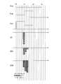
- 3 is a timing chart of each signal in the flowchart shown in FIG. 2.
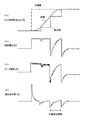
- FIG. 4 is a waveform diagram of a cam phase angle, a control voltage, a motor current, and a differential operation amount in the present invention. It is a waveform diagram of the cam phase angle, control voltage, motor current, and differential operation amount of a comparative example.
- FIG. 10 is a timing chart of each signal in the flowcharts shown in FIGS. 8 and 9.
- FIG. 10 is a timing chart of each signal in the flowcharts shown in FIGS. 8 and 9.
- FIG. 10 is a waveform diagram of a cam phase angle, a control voltage, a motor current, and a differential operation amount when the engine is rotating at a low speed in FIGS. 8 and 9. It is a flowchart which shows a part of procedure which calculates the brake operation amount in the variable valve timing control apparatus of the internal combustion engine which concerns on the 4th Embodiment of this invention. It is a flowchart which shows the procedure following FIG. 14 is a timing chart of each signal in the flowcharts shown in FIGS. 12 and 13. It is a flowchart which shows a part of procedure which calculates the brake operation amount in the variable valve timing control apparatus of the internal combustion engine which concerns on the 5th Embodiment of this invention. It is a flowchart which shows the procedure following FIG.
- FIG. 1 is a schematic diagram showing a system configuration of a vehicle engine to which a variable valve timing control device for an internal combustion engine according to an embodiment of the present invention is applied, and relates to control of an electric actuator used in a variable valve timing mechanism. The part is extracted and shown.
- crankshaft 2 of the engine (internal combustion engine) 1 Power from the crankshaft 2 of the engine (internal combustion engine) 1 is transmitted to the intake side camshaft 4 and the exhaust side camshaft 5 via a timing chain (or timing belt) 3.
- the intake valve is driven to open as the intake side camshaft 4 rotates, and the exhaust valve is driven to open as the exhaust side camshaft 5 rotates.
- the intake camshaft 4 is provided with a variable valve timing mechanism (VTC) 6 that changes the central phase of the intake valve operating angle by changing the rotational phase of the intake camshaft 4 with respect to the crankshaft 2. .
- VTC 6 changes the central phase of the valve operating angle of the intake valve forward and backward without changing the valve operating angle and valve lift amount of the intake valve.
- the VTC 6 is provided on the intake camshaft 4 side, but may be provided on the exhaust camshaft 5 side.
- crankshaft 2 is supported by a signal plate 8 provided with a detected portion (for example, a protruding portion) 7 and a crank angle sensor 9 for detecting the detected portion 7.
- the intake side camshaft 4 is pivotally supported by a signal plate 11 on which a detected portion (for example, a protruding portion) 10 is provided, and is provided with a cam angle sensor 12 for detecting the detected portion 10.
- the detection signal Ne of the crank angle sensor 9 and the detection signal Nc of the cam angle sensor 12 are respectively input to an engine control unit (ECU) 13 that controls the engine 1.
- the ECU 13 receives detection signals (intake air) from an air flow meter 14 that detects the amount of intake air of the engine 1, a temperature sensor 15 that measures environmental temperature, a voltmeter 16 that measures a power supply voltage for driving the motor of the electric VTC, and the like. Quantity Qa, environmental temperature T, and drive power supply voltage VMOT) are input.
- the ECU 13 performs various controls on the engine 1 by executing a control program stored in a storage device such as a read only memory (ROM) or a flash memory based on detection signals from the various sensors. Then, the ECU 13 calculates the engine speed RPM based on the detection signal Ne from the crank angle sensor 9, and performs fuel injection based on the calculated engine speed RPM, the intake air amount Qa detected by the air flow meter 14, and the like. In addition to performing control and ignition control, the control signal CS is supplied to the VTC 6 to control the valve timing.
- a control program stored in a storage device such as a read only memory (ROM) or a flash memory based on detection signals from the various sensors. Then, the ECU 13 calculates the engine speed RPM based on the detection signal Ne from the crank angle sensor 9, and performs fuel injection based on the calculated engine speed RPM, the intake air amount Qa detected by the air flow meter 14, and the like.
- the control signal CS is supplied to the VTC 6 to control the valve timing.
- convergence control such as PID control is used.
- the target valve timing (target advance amount) is calculated based on the engine speed RPM, the intake air amount Qa, and the like, and the crank angle sensor 9 and the cam angle are also calculated.
- the actual valve timing (actual advance angle amount) is detected, and according to the deviation between the target valve timing and the actual valve timing, the operation amount of the VTC 6, for example, the brake operation amount ( In the case of PID control, the differential operation amount) is calculated and feedback controlled.
- ECU13 works as a control unit which has a function as a control device of VTC6. Further, in the control of the VTC 6, the crank angle sensor 9 and the cam angle sensor 12 function as a measurement unit that periodically measures the valve timing.
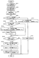
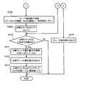
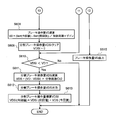
- FIG. 2 is a flowchart showing a procedure for calculating a brake operation amount in the variable valve timing control apparatus for an internal combustion engine according to the first embodiment of the present invention.
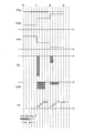
- FIG. 3 is a timing chart of each signal in the flowchart shown in FIG.
- step S101 the target angle ⁇ trg calculated by the ECU 13 based on the engine speed RPM, the intake air amount Qa, and the like is read.
- the target angle ⁇ trg is a predetermined value as shown in FIG.
- step S102 the detection angle ⁇ det based on the detection signal Nc from the cam angle sensor 12 is read.
- the detected angle ⁇ det is a constant value from each VTC position detection timing t0, t1, t2,... To the next timing, and rises stepwise toward the target angle ⁇ trg.
- This deviation amount ⁇ err decreases stepwise as the difference between the detected angle ⁇ det and the target angle ⁇ trg gradually decreases.
- step S104 it is determined whether or not the valve timing control period ⁇ T1 is smaller than the VTC angle detection period. This is because the load on the ECU 13 due to the calculation is reduced by applying the present invention only when the engine 1 is running at a low speed. If the valve timing control period ⁇ T1 is smaller than the VTC angle detection period, the process proceeds to step S105 to determine whether or not the VTC detection angle ⁇ det has been updated.
- a brake operation amount VD for example, a differential operation amount is calculated.
- the brake operation amount VD is expressed by the following equation (1).
- VD ( ⁇ err (current value) ⁇ err (previous value)) / control cycle ⁇ gain (1)
- the brake operation amount VD gradually decreases as the difference between the detected angle ⁇ det and the target angle ⁇ trg gradually decreases.
- This division counter Cs is for setting how many times the brake operation amount VD is to be output, and FIG. 3 shows an example of dividing into three.
- step S108 it is determined whether or not the count value of the division counter Cs is smaller than the predetermined division number Ct.
- the count value of the division counter Cs is set to the predetermined division. It is determined whether it is smaller than the number Ct.
- step S110 the divided brake operation amount VDS calculated according to the above equation (2) is output.
- This divided brake operation amount VDS is 1/3 of the brake operation amount VD as shown in FIG.
- step S104 If it is determined in step S104 that the valve timing control period ⁇ T1 is greater than the VTC angle detection period, the process proceeds to step S112, where a brake operation amount VD, for example, a differential operation amount is calculated.
- This brake operation amount VD is expressed by the following equation (3).
- VD ( ⁇ err (current value) ⁇ err (previous value)) / control cycle ⁇ gain (3)
- step S113 the brake operation amount VD is output, and the current valve timing control period ⁇ T1 ends.
- the above-described steps S101 to S111 are repeated every valve timing control period ⁇ T1, thereby dividing the brake operation amount VD into a plurality of divisions (in this example, three divisions) as shown in FIG.
- the brake operation amount VDS is output in a plurality of times according to the VTC position detection intervals t0-t1, t1-t2, t2-t3,... Within each VTC angle detection period.
- FIG. 3 shows an example in which the output is divided into three times between t1-t2 and t2-t3.
- the brake operation amount VD is not divided and is output at the VTC position detection timing.
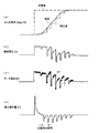
- FIGS. 4A to 4D are waveform diagrams of the cam phase angle, the control voltage, the motor current, and the differential operation amount in the present invention, respectively.
- FIGS. 5A to 5D are comparative examples, and show waveform diagrams of conventional cam phase angles, control voltages, motor currents, and differential manipulated variables (when the manipulated variables are applied collectively).
- the cam phase angle [deg. CA] indicates that the actual value (actual valve timing) rises gradually with respect to the target value (target valve timing) when the engine 1 is running at a low speed.
- a stepped detection value that approaches the target value is obtained for each period.
- the control voltage [V] at this time divides the brake operation amount VD into a plurality of times according to the VTC angle detection cycle as shown in FIG. 4B, and the valve timing control cycle ⁇ T1. Output every time.
- the time during which the brake operation amount VD remains at the peak is shortened.
- the motor current [A] decreases as the effective current decreases, and the current change amount ⁇ I1 becomes smaller than the conventional current change amount ⁇ I2.
- the differential operation amount (brake operation amount) [V] at this time becomes smaller by dividing into a plurality of outputs as shown in FIG. 4 (d) and FIG. 5 (d).
- differential operation amount calculation timing By gradually outputting, it is possible to reduce the effective current and the amount of current change while maintaining the brake function by the differential operation amount. As a result, it is possible to achieve both ensuring of VTC response performance by differential braking and effective current reduction. Further, the calculation load on the ECU 13 can be reduced by dividing the brake operation amount only when the engine is running at a low speed.
- the brake operation amount (differential operation amount) may be divided at a constant rate, the number of divisions may be two or more and less than the number of calculations in the angle detection cycle. At this time, the cycle of the divided output is set to be equal to or longer than the calculation cycle.
- the divided output of the brake operation amount (differential operation amount) can be realized by, for example, a low-pass filter, and the division ratio can be set by a filter coefficient.
- the filter coefficient includes a cut-off frequency and a gain coefficient, and a divided output can be obtained by setting the cut-off frequency and the gain coefficient.
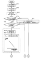
- FIG. 6 is a flowchart showing a procedure for calculating a brake operation amount in the variable valve timing control apparatus for an internal combustion engine according to the second embodiment of the present invention.
- FIG. 7 is a timing chart of each signal in the flowchart shown in FIG.
- Steps S201 to S206, S212, and S213 are the same as steps S101 to S106, S112, and S113, respectively, and thus description thereof is omitted.
- step S208 it is determined whether or not the integrated value VDSI of the divided brake operation amount VDS is smaller than the brake operation amount VD. If it is smaller, the brake operation amount VD necessary for convergence has not yet been reached, so the process proceeds to step S209.
- step S209 the divided brake operation amount VDS is calculated. This divided brake operation amount VDS is expressed by the following equation (4).
- VDS (VD ⁇ VDSI) ⁇ predetermined division coefficient Ck (4)
- the split brake operation amount VDS is initially large as shown in FIG. 7, and thereafter gradually decreased.
- the integrated value VDSI of the divided brake operation amount VDS is made substantially equal to the brake operation amount VD when the number of divisions is reached, for example.
- step S210 the split brake operation amount VDS is output.
- step S211 the integrated value VDSI of the divided brake operation amount is calculated.
- the integrated value VDSI of the divided brake operation amount is expressed by the following equation (5).
- VDSI (current value) VDSI (previous value) + VDS (current value) (5)
- steps S201 to S213 are repeated every valve timing control period ⁇ T1.
- the brake operation amount VD calculated in step S206 is largely output in the initial stage (first or early timing) within a range in which the operation amount is not saturated, thereby comparing with the first embodiment.
- the brake can be applied quickly and converged to the target value in a short time.
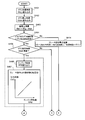
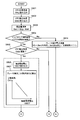
- FIGS. 8 and 9 are flowcharts showing a procedure for calculating the brake operation amount in the variable valve timing control apparatus for an internal combustion engine according to the third embodiment of the present invention.
- FIG. 10 is a timing chart of each signal in the flowcharts shown in FIGS.
- the number of divisions of the brake operation amount VD is switched according to the engine speed RPM.
- Steps S301 to S305 and S308 to S315 in FIG. 8 and FIG. 9 are the same as steps S101 to S113 in the first embodiment, and thus description thereof will be omitted, and only different parts will be described.
- step S306 the engine speed RPM is read.
- step S307 the division number Ct2 of the brake operation amount VD corresponding to the engine speed RPM is calculated. This division number Ct2 is decreased as the engine speed RPM is increased.
- FIG. 10 shows an example in which the division number Ct2 is set to 3 during the VTC position detection timing t1-t2 where the engine speed RPM is low, and the division number Ct2 is set to 2 between t2 and t3.
- the division of the brake operation amount VD can be realized by dividing the brake operation amount VD into a plurality of parts by, for example, a low-pass filter and switching the filter coefficient according to the engine speed RPM.
- the reason why the division number Ct2 is switched according to the VTC angle detection cycle determined from the engine speed RPM is that the optimum division number is different for the following reason.
- the first reason is that, as the engine speed RPM is lower, the VTC angle detection cycle becomes longer, so that the amount of change in the deviation amount is large and the brake operation amount VD calculated at a time is large. Therefore, the division number Ct2 is preferably set to be larger as the engine speed RPM is lower so that the operation amount after the division is not saturated.
- the second reason is that, as the engine speed RPM is lower, the VTC angle detection cycle is longer, so that a period during which the brake operation amount VD can be divided can be made longer and the division number Ct2 can be increased.
- the braking force can be secured, the effective current can be reduced, and the current variation can be reduced.
- FIGS. 4 (a) to 11 (d) show waveform diagrams of the cam phase angle, control voltage, motor current, and differential manipulated variable when the engine speed is lower than those in FIGS. 4 (a) to 4 (d).
- the position detection timing interval differs depending on the engine speed RPM, and is short when the engine speed is high and long when the engine speed is low.
- the position detection timing interval is related to the filter characteristics, and the optimum filter coefficient varies depending on the position detection interval.
- the braking force is secured by the optimal differential operation amount and the effective current is reduced.
- the parameter for switching the number of divisions is not limited to the engine rotation speed RPM, and the rotation speed of the rotating portion in the engine 1, for example, a crank rotation cycle or a VTC angle detection cycle may be used.
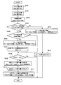
- [Fourth Embodiment] 12 and 13 are flowcharts showing the procedure for calculating the brake operation amount in the variable valve timing control apparatus for an internal combustion engine according to the fourth embodiment of the present invention.
- FIG. 14 is a timing chart of each signal in the flowcharts shown in FIGS.
- the fourth embodiment switches the division coefficient of the brake operation amount VD according to the engine speed RPM in the control of the second embodiment described above.
- Steps S401 to S405 and S408 to S415 in FIG. 12 and FIG. 13 are the same as steps S201 to S211 in the second embodiment, and thus description thereof will be omitted, and only different parts will be described.
- step S406 the engine speed RPM is read.
- step S407 a division coefficient Ck2 of the brake operation amount VD corresponding to the engine speed RPM is calculated. This division coefficient Ck2 is increased as the engine speed RPM is increased. Specifically, this can be realized by dividing the brake operation amount VD into a plurality by a low-pass filter and switching the filter coefficient in accordance with the engine speed RPM.
- the reason why the division coefficient Ck2 is switched according to the VTC angle detection cycle determined from the engine speed RPM is that the optimum division coefficient differs for the following reason.
- the first reason is that, as the engine speed RPM is lower, the VTC angle detection cycle is longer, so that the amount of change in the deviation amount is larger and the brake operation amount VD calculated at a time is larger. Therefore, the division coefficient Ck2 is preferably set to be smaller as the engine speed RPM is lower so that the operation amount after the division is not saturated.
- the second reason is that, as the engine speed RPM is lower, the VTC angle detection cycle is longer, so that the period during which the brake operation amount VD can be divided can be made longer and the division coefficient Ck2 can be reduced.
- the division parameter switching parameter is not limited to the engine rotational speed RPM, but the rotational speed of the rotating portion of the engine 1, for example, the crank rotational period or the VTC angle detection period. May be used.
- [Fifth Embodiment] 15 and 16 are flowcharts showing the procedure for calculating the brake operation amount in the variable valve timing control apparatus for an internal combustion engine according to the fifth embodiment of the present invention.
- the division method in addition to the control of the first embodiment described above, the division method is switched according to the environmental temperature T of the electric VTC. The higher the environmental temperature T, the lower the heat resistance limit of the motor. Therefore, the division method is switched to a direction in which the effective current does not increase. For example, the division number is increased as the environmental temperature T is higher. Alternatively, the peak value of the brake operation amount is suppressed.
- Steps S501 to S505 and S508 to S515 are the same as steps S101 to S11 in the first embodiment, and thus description thereof will be omitted and only different parts will be described.
- step S506 the environmental temperature T measured by the temperature sensor 15 is read.
- the environmental temperature T is a temperature that can be correlated with the electric VTC main body, such as the oil temperature, the water temperature, the outside air temperature, the intake air temperature, and the electric VTC main body temperature.
- the division number Ct2 of the brake operation amount VD corresponding to the read environment temperature T is calculated.
- This division number Ct2 is increased as the environmental temperature T increases.
- the division method can be switched in a direction in which the effective current does not increase so as not to exceed the motor heat resistance limit. Specifically, when the environmental temperature T becomes high, by increasing the number of divisions Ct2 of the brake operation amount VD, the effective current to the motor is reduced and the peak value of the brake operation amount is lowered to reduce the motor. Can suppress heat generation.
- FIGS. 17 and 18 are flowcharts showing a procedure for calculating the brake operation amount in the variable valve timing control device for the internal combustion engine according to the sixth embodiment of the present invention.
- the division method in addition to the control of the second embodiment described above, the division method is switched according to the environmental temperature T of the electric VTC. As described above, the higher the environmental temperature T, the lower the motor heat resistance limit. Therefore, the division method is switched to a direction in which the effective current does not increase. For example, the higher the environmental temperature T, the smaller the division factor. Alternatively, the peak value of the brake operation amount is suppressed.
- Steps S601 to S605 and S608 to S615 are the same as steps S201 to S211 in the second embodiment, and thus description thereof will be omitted and only different parts will be described.
- the environmental temperature T measured by the temperature sensor 15 is read.
- the environmental temperature T is a temperature that can be correlated with the electric VTC main body such as the oil temperature, the water temperature, the outside air temperature, the intake air temperature, and the electric VTC main body temperature.
- a division coefficient Ck2 of the brake operation amount VD corresponding to the read environment temperature T is calculated.
- the division coefficient Ck2 is decreased as the environmental temperature T is increased.
- FIG. 19 and 20 are flowcharts showing a procedure for calculating a brake operation amount in the variable valve timing control device for an internal combustion engine according to the seventh embodiment of the present invention.
- the division method is switched according to the power supply voltage VMOT for driving the motor of the electric VTC. If the drive power supply voltage VMOT for driving the motor of the electric VTC is low, the brake operation amount VD is likely to be saturated. Therefore, the division number Ck2 is increased as the drive power supply voltage VMOT is low. Alternatively, the peak value of the brake operation amount VD is suppressed.
- Steps S701 to S705 and S708 to S715 are the same as steps S101 to S111 in the first embodiment, and thus description thereof will be omitted and only different parts will be described.
- step S706 the drive power supply voltage VMOT of the electric VTC measured by the voltmeter 16 is read.
- step S707 the division number Ct2 of the brake operation amount VD corresponding to the read drive power supply voltage VMOT is calculated.
- the division number Ct2 is decreased as the drive power supply voltage VMOT is increased.
- the saturation of the brake operation amount VD can be suppressed by switching the division number Ct2 in accordance with the drive power supply voltage VMOT.
- FIGS. 21 and 22 are flowcharts showing the procedure for calculating the brake operation amount in the variable valve timing control apparatus for an internal combustion engine according to the eighth embodiment of the present invention.
- the division method is switched according to the drive power supply voltage VMOT of the electric VTC. If the drive power supply voltage VMOT of the electric VTC is low, the brake operation amount VD is likely to be saturated. Therefore, the lower the drive power supply voltage VMOT, the smaller the division coefficient Ck2. Alternatively, the peak value of the brake operation amount VD is suppressed.
- Steps S801 to S805 and S808 to S815 are the same as steps S201 to S211 in the second embodiment, and thus description thereof will be omitted and only different parts will be described.
- step S806 the drive power supply voltage VMOT of the electric VTC measured by the voltmeter 16 is read.
- step S807 a division coefficient Ck2 of the brake operation amount VD corresponding to the read drive power supply voltage VMOT is calculated.
- the division coefficient Ck2 is decreased as the drive power supply voltage VMOT is increased.
- the saturation of the brake operation amount VD can be suppressed by switching the division coefficient Ck2 in accordance with the drive power supply voltage VMOT.
- valve timing control by electric VTC depending on the engine temperature such as the starting water temperature or the oil temperature or the environmental condition such as the battery temperature or the battery voltage from the VTC default position at the start (during cranking) or at the time of low engine speed.
- the optimum valve timing can be controlled. Therefore, it is possible to achieve both the fuel efficiency effect due to the slow closing of the intake valve and the starting quality.
- SYMBOLS 1 Engine (internal combustion engine), 6 ... Variable valve timing mechanism (VTC), 9 ... Crank angle sensor, 12 ... Cam angle sensor, 13 ... ECU (calculation means), 14 ... Aero flow meter, 15 ... Temperature sensor, 16 ... Voltmeter, VD ... Brake operation amount, VDS ... Division brake operation amount, Ct, Ct2 ... Number of divisions, Ck, Ck2 ... Division coefficient
Landscapes
- Engineering & Computer Science (AREA)
- Chemical & Material Sciences (AREA)
- Combustion & Propulsion (AREA)
- Mechanical Engineering (AREA)
- General Engineering & Computer Science (AREA)
- Output Control And Ontrol Of Special Type Engine (AREA)
- Valve Device For Special Equipments (AREA)
Abstract
本発明は、内燃機関のバルブタイミングを変更する可変バルブタイミング制御装置及び制御方法に関する。バルブタイミングを制御する操作量を演算し、可変バルブタイミング機構の位置検出タイミングで演算された操作量を、次回の位置検出タイミングまでの間に分割して出力する。
Description
本発明は、内燃機関のバルブタイミングを変更する可変バルブタイミング制御装置及び制御方法に関する。
従来、内燃機関(エンジン)の可変動弁装置等で用いられる電動アクチュエータを制御する装置として、例えば特許文献1のように可変バルブタイミング機構(VTC)の位置を計測するセンサを設け、このセンサの計測結果に基づき目標位置に制御する手法が知られている。この特許文献1では、位相可変機構における遊星ギヤの旋回速度を可変するためのモータに、モータ回転速度センサを設け、カム軸の回転信号より検出頻度が高いモータ軸の回転信号によりVTC位置を検出している。
このように、モータ回転速度センサを設けることで、カム軸の回転信号が検出できない期間にもVTC位置の検出を行うことができ、エンジンの低回転領域での精度の良いバルブタイミング制御を実現している。このようなセンサの追加によるVTC位置検出システムは、エンジンの回転数に依存しないことから、エンジンが低回転時にも制御性を確保できる。
ところで、顧客要求や廉価なシステム要求により、VTC位置の検出を行う追加センサを省略することがある。この場合には、クランク角センサ等を用いてバルブタイミングを制御することとなる。そして、エンジンの運転状況に応じて目標バルブタイミングを演算すると共に、クランク角センサによる位置計測タイミングで実バルブタイミングを検出し、上記目標バルブタイミングと実バルブタイミングとの偏差に応じた微分操作量でフィードバック制御して目標値(目標バルブタイミング)に収束させる。
しかしながら、クランク角センサは位置計測頻度が少ないため、エンジン始動時(クランキング時)やエンジン低回転時の制御性を確保するためには、大きな微分操作量を用いた制御が必要となる。このため、実効電流や電流変化量の増大による影響への対処が課題となっていた。
すなわち、追加センサ不採用の場合、PID制御などの収束制御では、オーバーシュートなく目標値へ収束させるために、大きな微分操作量(ブレーキ)が必要となる。この大きな微分操作量により実効電流が増大し、モータ熱耐力への設計余裕がなくなったり、消費電力が増大して燃費効果が失われたりする。また、電流変化量が大きいとモータマグネットの減磁が発生する虞もある。
本発明は上記のような事情に鑑みてなされたもので、その目的とするところは、VTC位置検出用のセンサを追加することなく、ブレーキ機能を維持しつつ、実効電流や電流変化量の増大を抑制できる内燃機関の可変バルブタイミング制御装置及び制御方法を提供することにある。
本発明の内燃機関の可変バルブタイミング制御装置及び制御方法は、バルブタイミングを制御する操作量を演算し、可変バルブタイミング機構の位置検出タイミングで演算された操作量を、次回の位置検出タイミングまでの間に分割して出力する。
本発明では、可変バルブタイミング機構の位置検出タイミングで演算された操作量を一括で付与するのではなく、次回の位置検出タイミングまでの間に分割して出力することとした。これにより、操作量のピーク値を下げ、実効電流を低減させると共に電流変化量を小さくすることができ、付随して発生していた現象への対処を軽減または廃止できる。
従って、本発明によれば、VTC位置検出用のセンサを追加することなく、ブレーキ機能を維持しつつ、実効電流や電流変化量の増大を抑制できる。
従って、本発明によれば、VTC位置検出用のセンサを追加することなく、ブレーキ機能を維持しつつ、実効電流や電流変化量の増大を抑制できる。
以下、本発明の実施形態について図面を参照して説明する。
[第1の実施形態]
図1は、本発明の実施形態に係る内燃機関の可変バルブタイミング制御装置が適用される車両用エンジンのシステム構成を示す概略図であり、可変バルブタイミング機構で用いられる電動アクチュエータの制御に関係する部分を抽出して示している。
[第1の実施形態]
図1は、本発明の実施形態に係る内燃機関の可変バルブタイミング制御装置が適用される車両用エンジンのシステム構成を示す概略図であり、可変バルブタイミング機構で用いられる電動アクチュエータの制御に関係する部分を抽出して示している。
エンジン(内燃機関)1のクランクシャフト2からの動力は、タイミングチェーン(またはタイミングベルト)3を介して吸気側カムシャフト4及び排気側カムシャフト5に伝達される。そして、吸気側カムシャフト4の回転に伴って吸気バルブが開駆動され、排気側カムシャフト5の回転に伴って排気バルブが開駆動されるようになっている。
吸気側カムシャフト4には、クランクシャフト2に対する吸気側カムシャフト4の回転位相を変更することで、吸気バルブの作動角の中心位相を変化させる可変バルブタイミング機構(VTC)6が設けられている。このVTC6は、吸気バルブのバルブ作動角及びバルブリフト量を変えずに、吸気バルブのバルブ作動角の中心位相を進・遅角変化させるものである。ここでは、VTC6を吸気側カムシャフト4側に設けているが、排気側カムシャフト5側にも設けても良い。
また、クランクシャフト2には、被検出部(例えば突起部)7が設けられるシグナルプレート8が軸支されると共に、この被検出部7を検出するクランク角センサ9が設けられている。
更に、吸気側カムシャフト4には、被検出部(例えば突起部)10が設けられるシグナルプレート11が軸支されると共に、この被検出部10を検出するカム角センサ12が設けられている。
更に、吸気側カムシャフト4には、被検出部(例えば突起部)10が設けられるシグナルプレート11が軸支されると共に、この被検出部10を検出するカム角センサ12が設けられている。
クランク角センサ9の検出信号Ne及びカム角センサ12の検出信号Ncはそれぞれ、エンジン1の制御を行うエンジンコントロールユニット(ECU)13に入力される。このECU13には、エンジン1の吸入空気量を検出するエアフローメータ14、環境温度を測定する温度センサ15、及び電動VTCのモータを駆動する電源電圧を計測する電圧計16などから検出信号(吸入空気量Qa、環境温度T、及び駆動電源電圧VMOT)がそれぞれ入力される。
ECU13は、上記各種センサからの検出信号に基づき、Read Only Memory(ROM)やフラッシュメモリなどの記憶装置に記憶された制御プログラムを実行することで、エンジン1に対する種々の制御を行う。
そして、ECU13は、クランク角センサ9からの検出信号Neに基づいてエンジン回転数RPMを算出し、この算出したエンジン回転数RPMやエアフローメータ14で検出される吸入空気量Qaなどに基づいて燃料噴射制御や点火制御を行うと共に、VTC6に制御信号CSを供給してバルブタイミングの制御を行う。
そして、ECU13は、クランク角センサ9からの検出信号Neに基づいてエンジン回転数RPMを算出し、この算出したエンジン回転数RPMやエアフローメータ14で検出される吸入空気量Qaなどに基づいて燃料噴射制御や点火制御を行うと共に、VTC6に制御信号CSを供給してバルブタイミングの制御を行う。
VTC6の制御においては、PID制御などの収束制御が用いられ、エンジン回転数RPMや吸入空気量Qaなどに基づいて目標バルブタイミング(目標進角量)を演算すると共に、クランク角センサ9及びカム角センサ12からの検出信号Ne,Ncに基づいて実バルブタイミング(実進角量)を検出し、上記目標バルブタイミングと実バルブタイミングとの偏差に応じて、VTC6の操作量、例えばブレーキ操作量(PID制御の場合には微分操作量)を算出してフィードバック制御する。
この際、例えば制御信号CSのデューティ比を変更することで、最遅角位置から最進角位置までの間の任意の位置に、吸気バルブのバルブ作動角の中心位相(バルブタイミング)を変化させる。
このように、ECU13は、VTC6の制御装置としての機能を有する制御ユニットとして働く。また、VTC6の制御では、クランク角センサ9とカム角センサ12が、バルブタイミングを周期的に計測する計測手段として機能する。
このように、ECU13は、VTC6の制御装置としての機能を有する制御ユニットとして働く。また、VTC6の制御では、クランク角センサ9とカム角センサ12が、バルブタイミングを周期的に計測する計測手段として機能する。
次に、ECU13で実行されるVTC6の制御について、バルブタイミングを制御する操作量が、ブレーキ操作量の場合を例に取って詳しく説明する。
図2は、本発明の第1の実施形態に係る内燃機関の可変バルブタイミング制御装置におけるブレーキ操作量を算出する手順を示すフローチャートである。また、図3は、図2に示したフローチャートにおける各信号のタイミングチャートである。
図2は、本発明の第1の実施形態に係る内燃機関の可変バルブタイミング制御装置におけるブレーキ操作量を算出する手順を示すフローチャートである。また、図3は、図2に示したフローチャートにおける各信号のタイミングチャートである。
まず、ステップS101では、エンジン回転数RPMや吸入空気量Qaなどに基づいてECU13で算出した目標角度θtrgを読み込む。この目標角度θtrgは、図3に示すように所定値である。
ステップS102では、カム角センサ12からの検出信号Ncに基づく検出角度θdetを読み込む。検出角度θdetは、図3に示すように各VTC位置検出タイミングt0,t1,t2,…から次のタイミングまでの間は一定値であり、目標角度θtrgに向かって階段状に上昇する。
ステップS102では、カム角センサ12からの検出信号Ncに基づく検出角度θdetを読み込む。検出角度θdetは、図3に示すように各VTC位置検出タイミングt0,t1,t2,…から次のタイミングまでの間は一定値であり、目標角度θtrgに向かって階段状に上昇する。
ステップS103では、これらの目標角度θtrgと検出角度θdetとの偏差量θerr(θerr=θtrg-θdet)をECU13で演算する。この偏差量θerrは、検出角度θdetと目標角度θtrgとの差が徐々に小さくなることにより階段状に低下する。
次のステップS104では、バルブタイミング制御周期ΔT1がVTC角度検出周期よりも小さいか否かを判定する。これは、エンジン1が低回転時のみ本発明を適用することで、演算によるECU13への負荷を軽減するためである。
バルブタイミング制御周期ΔT1がVTC角度検出周期よりも小さい場合には、ステップS105に進み、VTCの検出角度θdetが更新されたか否かを判定する。
バルブタイミング制御周期ΔT1がVTC角度検出周期よりも小さい場合には、ステップS105に進み、VTCの検出角度θdetが更新されたか否かを判定する。
そして、VTC6の検出角度θdetが更新されたと判定されたときには、ステップS106に進み、ブレーキ操作量VD、例えば微分操作量を演算する。このブレーキ操作量VDは、次式(1)で表される。
VD=(θerr(今回値)-θerr(前回値))/制御周期×ゲイン…(1)
図3に示すように、ブレーキ操作量VDは、検出角度θdetと目標角度θtrgとの差が徐々に小さくなるのに対応して徐々に小さくなる。
VD=(θerr(今回値)-θerr(前回値))/制御周期×ゲイン…(1)
図3に示すように、ブレーキ操作量VDは、検出角度θdetと目標角度θtrgとの差が徐々に小さくなるのに対応して徐々に小さくなる。
次のステップS107では、分割カウンタCsをクリアする(Cs=0)。この分割カウンタCsは、ブレーキ操作量VDを何回に分けて出力するかを設定するためのものであり、図3では3分割する例を示している。
ステップS108では、分割カウンタCsのカウント値が所定分割数Ctより小さいか否かを判定する。また、ステップS105でVTC6の検出角度θdetが更新されていないと判定されたとき、換言すれば今回のVTC角度検出周期内であると判定されたときにも、分割カウンタCsのカウント値が所定分割数Ctより小さいか否かを判定する。
ステップS108では、分割カウンタCsのカウント値が所定分割数Ctより小さいか否かを判定する。また、ステップS105でVTC6の検出角度θdetが更新されていないと判定されたとき、換言すれば今回のVTC角度検出周期内であると判定されたときにも、分割カウンタCsのカウント値が所定分割数Ctより小さいか否かを判定する。
分割カウンタCsのカウント値が所定分割数Ctより小さい場合には、ステップS109に進み、分割ブレーキ操作量VDSを演算する。この演算は次式(2)にしたがって実行する。一方、分割カウンタCsのカウント値が所定分割数Ctより大きい場合には、分割数を超えたので処理を終了する。
VDS=VD×1/Ct…(2)
VDS=VD×1/Ct…(2)
ステップS110では、上式(2)にしたがって算出した分割ブレーキ操作量VDSを出力する。この分割ブレーキ操作量VDSは、図3に示すようにブレーキ操作量VDの1/3である。
ステップS111では、分割カウンタCsをカウントアップ(Cs(今回値)=Cs(前回値)+1)して今回のバルブタイミング制御周期ΔT1の処理を終了する。
ステップS111では、分割カウンタCsをカウントアップ(Cs(今回値)=Cs(前回値)+1)して今回のバルブタイミング制御周期ΔT1の処理を終了する。
上記ステップS104において、バルブタイミング制御周期ΔT1がVTC角度検出周期よりも大きいと判定されたときには、ステップS112に進み、ブレーキ操作量VD、例えば微分操作量を演算する。このブレーキ操作量VDは、次式(3)で表される。
VD=(θerr(今回値)-θerr(前回値))/制御周期×ゲイン…(3)
そして、ステップS113でブレーキ操作量VDを出力して今回のバルブタイミング制御周期ΔT1を終了する。
VD=(θerr(今回値)-θerr(前回値))/制御周期×ゲイン…(3)
そして、ステップS113でブレーキ操作量VDを出力して今回のバルブタイミング制御周期ΔT1を終了する。
エンジン1が低回転時には、上述したステップS101~S111の処理をバルブタイミング制御周期ΔT1毎に繰り返すことで、図3に示したようにブレーキ操作量VDを複数分割(本例では3分割)した分割ブレーキ操作量VDSを、各VTC角度検出周期内にVTCの位置検出間隔t0-t1,t1-t2,t2-t3,…に応じて、複数回に分けて出力する。図3では、t1-t2間、t2-t3間にそれぞれ3回に分けて出力する例を示している。
一方、エンジン1が高回転時には、ステップS112,S113に示すように、ブレーキ操作量VDを分割せずに、VTCの位置検出タイミングで出力する。
一方、エンジン1が高回転時には、ステップS112,S113に示すように、ブレーキ操作量VDを分割せずに、VTCの位置検出タイミングで出力する。
図4(a)~(d)はそれぞれ、本発明におけるカム位相角、制御電圧、モータ電流、及び微分操作量の波形図である。図5(a)~(d)は比較例であり、従来(操作量を一括で付与する場合)のカム位相角、制御電圧、モータ電流、及び微分操作量の波形図を示している。
図4(a)及び図5(a)に示すように、カム位相角[deg.CA]は、エンジン1が低回転のときには、目標値(目標バルブタイミング)に対して実値(実バルブタイミング)は緩やかに立ち上がり、クランク角センサ9による低頻度のVTC位置検出では、VTC角度検出周期毎に目標値に近づく階段状の検出値が得られる。
図4(a)及び図5(a)に示すように、カム位相角[deg.CA]は、エンジン1が低回転のときには、目標値(目標バルブタイミング)に対して実値(実バルブタイミング)は緩やかに立ち上がり、クランク角センサ9による低頻度のVTC位置検出では、VTC角度検出周期毎に目標値に近づく階段状の検出値が得られる。
この時の制御電圧[V]は、本第1の実施形態では、図4(b)に示すようにブレーキ操作量VDを、VTC角度検出周期に応じて複数回に分け、バルブタイミング制御周期ΔT1毎に出力する。これによって、図5(b)と比較すれば明らかなように、ブレーキ操作量VDがピークに留まる時間が短くなる。
また、モータ電流[A]は、図4(c)と図5(c)に対比して示すように、実効電流が減少すると共に、電流変化量ΔI1も従来の電流変化量ΔI2より小さくなる。
この時の微分操作量(ブレーキ操作量)[V]は、図4(d)と図5(d)に対比して示すように、複数に分割して出力することによって小さくなる。
また、モータ電流[A]は、図4(c)と図5(c)に対比して示すように、実効電流が減少すると共に、電流変化量ΔI1も従来の電流変化量ΔI2より小さくなる。
この時の微分操作量(ブレーキ操作量)[V]は、図4(d)と図5(d)に対比して示すように、複数に分割して出力することによって小さくなる。
従って、上述した第1の実施形態によれば、VTC位置検出タイミングで演算される大きな微分操作量(ブレーキ操作量)を、次回のVTC位置検出タイミング(=微分操作量演算タイミング)までの区間で徐々に出力することで、微分操作量によるブレーキ機能を維持しつつ、実効電流と電流変化量を減らすことができる。これによって、微分ブレーキによるVTC応答性能の確保と実効電流低減を両立させることができる。また、エンジンが低回転時のみブレーキ操作量を分割することでECU13の演算負荷を軽減できる。
なお、ブレーキ操作量(微分操作量)は、一定の割合で分割すればよいので、分割数は2分割以上で、角度検出周期中の演算数以下にすれば良い。この際、分割出力の周期は、演算周期以上とする。
上記ブレーキ操作量(微分操作量)の分割出力は、例えばローパスフィルタで実現でき、分割する割合はフィルタ係数により設定できる。フィルタ係数には、カットオフ周波数とゲイン係数等が該当し、カットオフ周波数とゲイン係数の設定により分割出力を得ることができる。
上記ブレーキ操作量(微分操作量)の分割出力は、例えばローパスフィルタで実現でき、分割する割合はフィルタ係数により設定できる。フィルタ係数には、カットオフ周波数とゲイン係数等が該当し、カットオフ周波数とゲイン係数の設定により分割出力を得ることができる。
[第2の実施形態]
図6は、本発明の第2の実施形態に係る内燃機関の可変バルブタイミング制御装置におけるブレーキ操作量を算出する手順を示すフローチャートである。また、図7は、図6に示したフローチャートにおける各信号のタイミングチャートである。
図6は、本発明の第2の実施形態に係る内燃機関の可変バルブタイミング制御装置におけるブレーキ操作量を算出する手順を示すフローチャートである。また、図7は、図6に示したフローチャートにおける各信号のタイミングチャートである。
前述した第1の実施形態ではブレーキ操作量VDを一定の割合で分割したのに対し、本第2の実施形態では初期に大きくし、徐々に小さくなるように分割している。
ステップS201~S206及びS212,S213は、それぞれステップS101~S106及びS112,S113と同様であるので説明を省略する。
ステップS201~S206及びS212,S213は、それぞれステップS101~S106及びS112,S113と同様であるので説明を省略する。
ステップS207では、分割ブレーキ操作量の積算値VDSIをクリアする(VDSI=0)。
そして、ステップS208で、分割ブレーキ操作量VDSの積算値VDSIがブレーキ操作量VDより小さいか否か判定する。小さければまだ収束に必要なブレーキ操作量VDに達していないのでステップS209に進み、大きければ収束に必要なブレーキ操作量VDを超えたので今回のバルブタイミング制御周期ΔT1を終了する。
ステップS209では、分割ブレーキ操作量VDSを演算する。この分割ブレーキ操作量VDSは、下式(4)で表される。
VDS=(VD-VDSI)×所定分割係数Ck…(4)
本第2の実施形態では、分割ブレーキ操作量VDSは、図7に示すように最初は大きく、その後は徐々に小さくする。この分割ブレーキ操作量VDSの積算値VDSIは、例えば分割数に達した時点でブレーキ操作量VDと実質的に等しくする。
次のステップS210では、分割ブレーキ操作量VDSを出力する。
ステップS211では、分割ブレーキ操作量の積算値VDSIを演算する。この分割ブレーキ操作量の積算値VDSIは、次式(5)で表される。
VDSI(今回値)=VDSI(前回値)+VDS(今回値)…(5)
そして、上記ステップS201~S213の動作をバルブタイミング制御周期ΔT1毎に繰り返す。
ステップS211では、分割ブレーキ操作量の積算値VDSIを演算する。この分割ブレーキ操作量の積算値VDSIは、次式(5)で表される。
VDSI(今回値)=VDSI(前回値)+VDS(今回値)…(5)
そして、上記ステップS201~S213の動作をバルブタイミング制御周期ΔT1毎に繰り返す。
上記のような制御によれば、ステップS206で演算したブレーキ操作量VDを操作量が飽和しない範囲内で初期(最初、または早いタイミング)に大きく出力することで、第1の実施形態と比較して早くブレーキをかけることができ、短時間で目標値に収束させることができる。
[第3の実施形態]
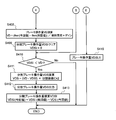
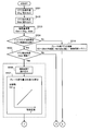
図8及び図9は、本発明の第3の実施形態に係る内燃機関の可変バルブタイミング制御装置におけるブレーキ操作量を算出する手順を示すフローチャートである。また、図10は、図8及び図9に示したフローチャートにおける各信号のタイミングチャートである。
本第3の実施形態は、前述した第1の実施形態の制御に加えて、エンジン回転数RPMに応じてブレーキ操作量VDの分割数を切り換えるものである。
図8及び図9は、本発明の第3の実施形態に係る内燃機関の可変バルブタイミング制御装置におけるブレーキ操作量を算出する手順を示すフローチャートである。また、図10は、図8及び図9に示したフローチャートにおける各信号のタイミングチャートである。
本第3の実施形態は、前述した第1の実施形態の制御に加えて、エンジン回転数RPMに応じてブレーキ操作量VDの分割数を切り換えるものである。
図8及び図9におけるステップS301~S305及びS308~S315は、第1の実施形態におけるステップS101~S113と同様であるので説明を省略し、異なる部分についてのみ述べる。
ステップS306では、エンジン回転数RPMを読み込む。
次のステップS307では、エンジン回転数RPMに応じたブレーキ操作量VDの分割数Ct2を算出する。この分割数Ct2は、エンジン回転数RPMの高速化に伴って減少させる。図10では、エンジン回転数RPMが低いVTCの位置検出タイミングt1-t2間に分割数Ct2を3にし、t2-t3間に分割数Ct2を2にした例を示している。
ブレーキ操作量VDの分割は、例えばローパスフィルタにより複数に分割し、エンジン回転数RPMに応じてフィルタ係数を切り換えることで実現できる。
ステップS306では、エンジン回転数RPMを読み込む。
次のステップS307では、エンジン回転数RPMに応じたブレーキ操作量VDの分割数Ct2を算出する。この分割数Ct2は、エンジン回転数RPMの高速化に伴って減少させる。図10では、エンジン回転数RPMが低いVTCの位置検出タイミングt1-t2間に分割数Ct2を3にし、t2-t3間に分割数Ct2を2にした例を示している。
ブレーキ操作量VDの分割は、例えばローパスフィルタにより複数に分割し、エンジン回転数RPMに応じてフィルタ係数を切り換えることで実現できる。
このように、エンジン回転数RPMから決まるVTC角度検出周期に応じて、分割数Ct2を切り換えるのは、以下の理由で最適な分割数が異なるためである。
第1の理由は、エンジン回転数RPMが低い程、VTC角度検出周期が長くなるため、偏差量の変化量が大きく、一度に演算されるブレーキ操作量VDが大きいからである。従って、分割後の操作量が飽和しないように、分割数Ct2はエンジン回転数RPMが低い程、大きく設定すると良い。
第2の理由は、エンジン回転数RPMが低い程、VTC角度検出周期が長いため、ブレーキ操作量VDを分割できる期間を長く取れ、分割数Ct2を大きくできるからである。
第1の理由は、エンジン回転数RPMが低い程、VTC角度検出周期が長くなるため、偏差量の変化量が大きく、一度に演算されるブレーキ操作量VDが大きいからである。従って、分割後の操作量が飽和しないように、分割数Ct2はエンジン回転数RPMが低い程、大きく設定すると良い。
第2の理由は、エンジン回転数RPMが低い程、VTC角度検出周期が長いため、ブレーキ操作量VDを分割できる期間を長く取れ、分割数Ct2を大きくできるからである。
上記のようにエンジン回転数RPMに応じて、ブレーキ操作量VDの分割数を切り換えることで、エンジン回転数RPMから決まるVTC角度検出周期に応じて最適な分割数に設定でき、最適な微分操作量によるブレーキ力確保と実効電流の低減及び電流変化量の減少が実現できる。
図11(a)~(d)は、エンジン回転が図4(a)~(d)より更に低い場合のカム位相角、制御電圧、モータ電流、及び微分操作量の波形図を示している。図4(d)と図11(d)を比較すれば明らかなように、エンジン回転数RPMによって位置検出タイミングの間隔が異なり、エンジン回転が高い場合は短く、低い場合には長くなる。この位置検出タイミングの間隔はフィルタの特性に関係しており、位置検出間隔により最適なフィルタ係数が異なる。
エンジン回転数RPMに応じて、図11(d)に示す微分操作量と、図4(d)に示す微分操作量とを切り換えることで、最適な微分操作量によるブレーキ力確保と実効電流の低減を図れる。
なお、分割数の切換えパラメータは、エンジン回転数RPMに限られるものではなく、エンジン1における回転部の回転数、例えばクランク回転周期、あるいはVTC角度検出周期などを利用しても良い。
なお、分割数の切換えパラメータは、エンジン回転数RPMに限られるものではなく、エンジン1における回転部の回転数、例えばクランク回転周期、あるいはVTC角度検出周期などを利用しても良い。
[第4の実施形態]
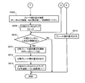
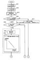
図12及び図13は、本発明の第4の実施形態に係る内燃機関の可変バルブタイミング制御装置におけるブレーキ操作量を算出する手順を示すフローチャートである。また、図14は、図12及び図13に示したフローチャートにおける各信号のタイミングチャートである。
本第4の実施形態は、前述した第2の実施形態の制御において、エンジン回転数RPMに応じてブレーキ操作量VDの分割係数を切り換えるものである。
図12及び図13は、本発明の第4の実施形態に係る内燃機関の可変バルブタイミング制御装置におけるブレーキ操作量を算出する手順を示すフローチャートである。また、図14は、図12及び図13に示したフローチャートにおける各信号のタイミングチャートである。
本第4の実施形態は、前述した第2の実施形態の制御において、エンジン回転数RPMに応じてブレーキ操作量VDの分割係数を切り換えるものである。
図12及び図13におけるステップS401~S405及びS408~S415は、第2の実施形態におけるステップS201~S211と同様であるので説明を省略し、異なる部分についてのみ述べる。
ステップS406では、エンジン回転数RPMを読み込む。
次のステップS407では、エンジン回転数RPMに応じたブレーキ操作量VDの分割係数Ck2を算出する。この分割係数Ck2は、エンジン回転数RPMの高速化に伴って増大させる。
具体的には、ローパスフィルタによりブレーキ操作量VDを複数に分割し、エンジン回転数RPMに応じてフィルタ係数を切り換えることで実現できる。
ステップS406では、エンジン回転数RPMを読み込む。
次のステップS407では、エンジン回転数RPMに応じたブレーキ操作量VDの分割係数Ck2を算出する。この分割係数Ck2は、エンジン回転数RPMの高速化に伴って増大させる。
具体的には、ローパスフィルタによりブレーキ操作量VDを複数に分割し、エンジン回転数RPMに応じてフィルタ係数を切り換えることで実現できる。
このように、エンジン回転数RPMから決まるVTC角度検出周期に応じて、分割係数Ck2を切り換えるのは、以下の理由で最適な分割係数が異なるためである。
第1の理由は、エンジン回転数RPMが低い程、VTC角度検出周期が長いため、偏差量の変化量が大きく、一度に演算されるブレーキ操作量VDが大きいからである。従って、分割後の操作量が飽和しないように、分割係数Ck2はエンジン回転数RPMが低い程、小さく設定すると良い。
第2の理由は、エンジン回転数RPMが低い程、VTC角度検出周期が長いため、ブレーキ操作量VDを分割できる期間を長く取れ、分割係数Ck2を小さくできるからである。
第1の理由は、エンジン回転数RPMが低い程、VTC角度検出周期が長いため、偏差量の変化量が大きく、一度に演算されるブレーキ操作量VDが大きいからである。従って、分割後の操作量が飽和しないように、分割係数Ck2はエンジン回転数RPMが低い程、小さく設定すると良い。
第2の理由は、エンジン回転数RPMが低い程、VTC角度検出周期が長いため、ブレーキ操作量VDを分割できる期間を長く取れ、分割係数Ck2を小さくできるからである。
上記のようにエンジン回転数RPMに応じて、分割係数Ck2を切り換えることで、エンジン回転数RPMから決まるVTC角度検出周期に応じて最適な分割係数に設定できる。
なお、分割係数の切換えパラメータは、第3の実施形態と同様に、エンジン回転数RPMに限られるものではなく、エンジン1における回転部の回転数、例えばクランク回転周期、あるいはVTC角度検出周期などを利用しても良い。
なお、分割係数の切換えパラメータは、第3の実施形態と同様に、エンジン回転数RPMに限られるものではなく、エンジン1における回転部の回転数、例えばクランク回転周期、あるいはVTC角度検出周期などを利用しても良い。
[第5の実施形態]
図15及び図16は、本発明の第5の実施形態に係る内燃機関の可変バルブタイミング制御装置におけるブレーキ操作量を算出する手順を示すフローチャートである。本第5の実施形態は、前述した第1の実施形態の制御に加えて電動VTCの環境温度Tに応じて分割方法を切り換えるものである。
環境温度Tが高い程、モータ耐熱限界が低くなるため、分割方法を実効電流が増大しない方向に切り換える。例えば、環境温度Tが高い程、分割数を増やす。または、ブレーキ操作量のピーク値を抑えるようにする。
図15及び図16は、本発明の第5の実施形態に係る内燃機関の可変バルブタイミング制御装置におけるブレーキ操作量を算出する手順を示すフローチャートである。本第5の実施形態は、前述した第1の実施形態の制御に加えて電動VTCの環境温度Tに応じて分割方法を切り換えるものである。
環境温度Tが高い程、モータ耐熱限界が低くなるため、分割方法を実効電流が増大しない方向に切り換える。例えば、環境温度Tが高い程、分割数を増やす。または、ブレーキ操作量のピーク値を抑えるようにする。
ステップS501~S505及びS508~S515は、第1の実施形態におけるステップS101~S11と同様であるので説明を省略し、異なる部分について述べる。
ステップS506では、温度センサ15で計測した環境温度Tを読み込む。ここで、環境温度Tは、油温、水温、外気温、吸気温度、及び電動VTC本体温度等、電動VTC本体と相関が取れる温度とする。
ステップS506では、温度センサ15で計測した環境温度Tを読み込む。ここで、環境温度Tは、油温、水温、外気温、吸気温度、及び電動VTC本体温度等、電動VTC本体と相関が取れる温度とする。
次のステップS507では、読み込んだ環境温度Tに応じたブレーキ操作量VDの分割数Ct2を算出する。この分割数Ct2は、環境温度Tの上昇に伴って増大させる。
上記のように環境温度Tに応じて、分割数Ct2を切り換えることで、モータ耐熱限界を超えないように、分割方法を実効電流が増大しない方向に切り換えることができる。
具体的には、環境温度Tが高温になったときに、ブレーキ操作量VDの分割数Ct2を増大させることで、モータへの実効電流を低減すると共に、ブレーキ操作量のピーク値を下げてモータの発熱を抑えることができる。
上記のように環境温度Tに応じて、分割数Ct2を切り換えることで、モータ耐熱限界を超えないように、分割方法を実効電流が増大しない方向に切り換えることができる。
具体的には、環境温度Tが高温になったときに、ブレーキ操作量VDの分割数Ct2を増大させることで、モータへの実効電流を低減すると共に、ブレーキ操作量のピーク値を下げてモータの発熱を抑えることができる。
[第6の実施形態]
図17及び図18は、本発明の第6の実施形態に係る内燃機関の可変バルブタイミング制御装置におけるブレーキ操作量を算出する手順を示すフローチャートである。本第6の実施形態は、前述した第2の実施形態の制御に加えて電動VTCの環境温度Tに応じて分割方法を切り換えるものである。
上述したように、環境温度Tが高い程、モータ耐熱限界が低くなるため、分割方法を実効電流が増大しない方向に切り換える。例えば、環境温度Tが高い程、分割係数を小さくする。または、ブレーキ操作量のピーク値を抑えるようにする。
図17及び図18は、本発明の第6の実施形態に係る内燃機関の可変バルブタイミング制御装置におけるブレーキ操作量を算出する手順を示すフローチャートである。本第6の実施形態は、前述した第2の実施形態の制御に加えて電動VTCの環境温度Tに応じて分割方法を切り換えるものである。
上述したように、環境温度Tが高い程、モータ耐熱限界が低くなるため、分割方法を実効電流が増大しない方向に切り換える。例えば、環境温度Tが高い程、分割係数を小さくする。または、ブレーキ操作量のピーク値を抑えるようにする。
ステップS601~S605及びS608~S615は、第2の実施形態におけるステップS201~S211と同様であるので説明を省略し、異なる部分について述べる。
ステップS606では、温度センサ15で計測した環境温度Tを読み込む。ここで、環境温度Tは、油温、水温、外気温、吸気温度、及び電動VTC本体温度等、電動VTC本体と相関が取れる温度とする。
ステップS606では、温度センサ15で計測した環境温度Tを読み込む。ここで、環境温度Tは、油温、水温、外気温、吸気温度、及び電動VTC本体温度等、電動VTC本体と相関が取れる温度とする。
次のステップS607では、読み込んだ環境温度Tに応じたブレーキ操作量VDの分割係数Ck2を算出する。この分割係数Ck2は、環境温度Tの上昇に伴って低下させる。
上記のように環境温度Tに応じて、分割係数Ck2を切り換えることで、モータ耐熱限界を超えないように、分割方法を実効電流が増大しない方向に切り換えることができる。
上記のように環境温度Tに応じて、分割係数Ck2を切り換えることで、モータ耐熱限界を超えないように、分割方法を実効電流が増大しない方向に切り換えることができる。
[第7の実施形態]
図19及び図20は、本発明の第7の実施形態に係る内燃機関の可変バルブタイミング制御装置におけるブレーキ操作量を算出する手順を示すフローチャートである。本第7の実施形態は、前述した第1の実施形態の制御に加えて電動VTCのモータを駆動する電源電圧VMOTに応じて分割方法を切り換えるものである。
電動VTCのモータを駆動する駆動電源電圧VMOTが低いとブレーキ操作量VDの飽和が発生しやすくなるため、駆動電源電圧VMOTが低い程、分割数Ck2を増やすようにしている。または、ブレーキ操作量VDのピーク値を抑えるようにする。
図19及び図20は、本発明の第7の実施形態に係る内燃機関の可変バルブタイミング制御装置におけるブレーキ操作量を算出する手順を示すフローチャートである。本第7の実施形態は、前述した第1の実施形態の制御に加えて電動VTCのモータを駆動する電源電圧VMOTに応じて分割方法を切り換えるものである。
電動VTCのモータを駆動する駆動電源電圧VMOTが低いとブレーキ操作量VDの飽和が発生しやすくなるため、駆動電源電圧VMOTが低い程、分割数Ck2を増やすようにしている。または、ブレーキ操作量VDのピーク値を抑えるようにする。
ステップS701~S705及びS708~S715は、第1の実施形態におけるステップS101~S111と同様であるので説明を省略し、異なる部分について述べる。
ステップS706では、電圧計16で測定した電動VTCの駆動電源電圧VMOTを読み込む。
次のステップS707では、読み込んだ駆動電源電圧VMOTに応じたブレーキ操作量VDの分割数Ct2を算出する。この分割数Ct2は、駆動電源電圧VMOTの上昇に伴って低下させる。
上記のように駆動電源電圧VMOTに応じて、分割数Ct2を切り換えることで、ブレーキ操作量VDの飽和を抑制することができる。
ステップS706では、電圧計16で測定した電動VTCの駆動電源電圧VMOTを読み込む。
次のステップS707では、読み込んだ駆動電源電圧VMOTに応じたブレーキ操作量VDの分割数Ct2を算出する。この分割数Ct2は、駆動電源電圧VMOTの上昇に伴って低下させる。
上記のように駆動電源電圧VMOTに応じて、分割数Ct2を切り換えることで、ブレーキ操作量VDの飽和を抑制することができる。
[第8の実施形態]
図21及び図22は、本発明の第8の実施形態に係る内燃機関の可変バルブタイミング制御装置におけるブレーキ操作量を算出する手順を示すフローチャートである。本第8の実施形態は、前述した第2の実施形態の制御に加えて電動VTCの駆動電源電圧VMOTに応じて分割方法を切り換えるものである。
電動VTCの駆動電源電圧VMOTが低いとブレーキ操作量VDの飽和が発生しやすくなるため、駆動電源電圧VMOTが低い程、分割係数Ck2を小さくするようにしている。または、ブレーキ操作量VDのピーク値を抑えるようにする。
図21及び図22は、本発明の第8の実施形態に係る内燃機関の可変バルブタイミング制御装置におけるブレーキ操作量を算出する手順を示すフローチャートである。本第8の実施形態は、前述した第2の実施形態の制御に加えて電動VTCの駆動電源電圧VMOTに応じて分割方法を切り換えるものである。
電動VTCの駆動電源電圧VMOTが低いとブレーキ操作量VDの飽和が発生しやすくなるため、駆動電源電圧VMOTが低い程、分割係数Ck2を小さくするようにしている。または、ブレーキ操作量VDのピーク値を抑えるようにする。
ステップS801~S805及びS808~S815は、第2の実施形態におけるステップS201~S211と同様であるので説明を省略し、異なる部分について述べる。
ステップS806では、電圧計16で計測した電動VTCの駆動電源電圧VMOTを読み込む。
次のステップS807では、読み込んだ駆動電源電圧VMOTに応じたブレーキ操作量VDの分割係数Ck2を算出する。この分割係数Ck2は、駆動電源電圧VMOTの上昇に伴って低下させる。
上記のように駆動電源電圧VMOTに応じて、分割係数Ck2を切り換えることで、ブレーキ操作量VDの飽和を抑制することができる。
ステップS806では、電圧計16で計測した電動VTCの駆動電源電圧VMOTを読み込む。
次のステップS807では、読み込んだ駆動電源電圧VMOTに応じたブレーキ操作量VDの分割係数Ck2を算出する。この分割係数Ck2は、駆動電源電圧VMOTの上昇に伴って低下させる。
上記のように駆動電源電圧VMOTに応じて、分割係数Ck2を切り換えることで、ブレーキ操作量VDの飽和を抑制することができる。
以上のように、電動VTCによるバルブタイミング制御において、始動時(クランキング時)やエンジン低回転時に、VTCデフォルト位置から、始動水温や油温などの環境温度あるいはバッテリー電圧などのエンジンの状況に応じた最適なバルブタイミングに制御できる。従って、吸気バルブの遅閉じによる燃費効果と始動品質を両立できる。
1…エンジン(内燃機関)、6…可変バルブタイミング機構(VTC)、9…クランク角センサ、12…カム角センサ、13…ECU(演算手段)、14…エアロフローメータ、15…温度センサ、16…電圧計、VD…ブレーキ操作量、VDS…分割ブレーキ操作量、Ct,Ct2…分割数、Ck,Ck2…分割係数
Claims (16)
- 内燃機関のバルブタイミングを変更する可変バルブタイミング機構を制御する制御装置において、
バルブタイミングを制御する操作量を演算する演算手段を備え、該演算手段により可変バルブタイミング機構の位置検出タイミングで演算された操作量を、次回の位置検出タイミングまでの間に分割して出力する、内燃機関の可変バルブタイミング制御装置。 - 前記操作量の分割の割合を、前記可変バルブタイミング機構の角度検出周期に応じて切り換える、請求項1記載の内燃機関の可変バルブタイミング制御装置。
- 前記操作量の分割の切り換えを、前記可変バルブタイミング機構の位置検出タイミングで行う、請求項2記載の内燃機関の可変バルブタイミング制御装置。
- 前記操作量の分割の割合を、前記内燃機関の回転数に応じて切り換える、請求項1記載の内燃機関の可変バルブタイミング制御装置。
- 前記操作量の分割の切り換えを、前記可変バルブタイミング機構の位置検出タイミングで行う、請求項4記載の内燃機関の可変バルブタイミング制御装置。
- 前記操作量の分割は、初期に大きくし、徐々に小さくする、請求項1記載の内燃機関の可変バルブタイミング制御装置。
- 前記操作量の分割は、環境温度に応じて切り換える、請求項1記載の内燃機関の可変バルブタイミング制御装置。
- 前記環境温度が高温になったときに、前記操作量の分割方法を実効電流が増大しない方向に切り換える、請求項7記載の内燃機関の可変バルブタイミング制御装置。
- 前記操作量は、収束制御のブレーキ操作量である、請求項1記載の内燃機関の可変バルブタイミング制御装置。
- 前記操作量の分割は、前記可変バルブタイミング機構を駆動するモータの駆動電源電圧に応じて切り換える、請求項1記載の内燃機関の可変バルブタイミング制御装置。
- 前記可変バルブタイミング機構を駆動するモータの駆動電源電圧が低いときに分割数を増やす、請求項10記載の内燃機関の可変バルブタイミング制御装置。
- 内燃機関のバルブタイミングを変更する可変バルブタイミング機構を制御する制御方法において、
バルブタイミングを制御する操作量を演算し、
可変バルブタイミング機構の位置検出タイミングで演算された操作量を分割し、
前記分割した操作量を、次回の位置検出タイミングまでの間に出力する、内燃機関の可変バルブタイミング制御方法。 - 前記バルブタイミングを制御する操作量を演算するステップが、以下のステップを含む請求項12記載の内燃機関の可変バルブタイミング制御方法、
目標バルブタイミングを演算すると共に、実バルブタイミングを検出し、
前記目標バルブタイミングと前記実バルブタイミングとの偏差に応じて、前記操作量を算出する。 - 前記可変バルブタイミング機構の位置検出タイミングで演算された操作量を分割するステップが、以下のステップを含む請求項12記載の内燃機関の可変バルブタイミング制御方法、
前記操作量をフィルタにより複数に分割し、
分割する割合をフィルタ係数により設定する。 - 前記フィルタにより操作量を複数に分割するステップが、以下のステップを含む請求項14記載の内燃機関の可変バルブタイミング制御方法、
環境温度に応じて分割方法を切り換える。 - 前記分割する割合をフィルタ係数により設定するステップの後に、以下のステップを更に含む請求項14記載の内燃機関の可変バルブタイミング制御方法、
前記内燃機関の回転数に応じてフィルタ係数を切り換える。
Priority Applications (3)
| Application Number | Priority Date | Filing Date | Title |
|---|---|---|---|
| US14/432,284 US9410488B2 (en) | 2013-06-06 | 2014-03-07 | Variable valve timing control device for internal combustion engine, and control method |
| CN201480002291.6A CN104603426B (zh) | 2013-06-06 | 2014-03-07 | 内燃机的可变气门正时控制装置及控制方法 |
| DE112014002734.0T DE112014002734T5 (de) | 2013-06-06 | 2014-03-07 | Variable Ventilsteuerungsvorrichtung für einen Verbrennungsmotor und Steuerungsverfahren |
Applications Claiming Priority (2)
| Application Number | Priority Date | Filing Date | Title |
|---|---|---|---|
| JP2013120036A JP6018019B2 (ja) | 2013-06-06 | 2013-06-06 | 内燃機関の可変バルブタイミング制御装置 |
| JP2013-120036 | 2013-06-06 |
Publications (1)
| Publication Number | Publication Date |
|---|---|
| WO2014196237A1 true WO2014196237A1 (ja) | 2014-12-11 |
Family
ID=52007893
Family Applications (1)
| Application Number | Title | Priority Date | Filing Date |
|---|---|---|---|
| PCT/JP2014/055933 Ceased WO2014196237A1 (ja) | 2013-06-06 | 2014-03-07 | 内燃機関の可変バルブタイミング制御装置及び制御方法 |
Country Status (5)
| Country | Link |
|---|---|
| US (1) | US9410488B2 (ja) |
| JP (1) | JP6018019B2 (ja) |
| CN (1) | CN104603426B (ja) |
| DE (1) | DE112014002734T5 (ja) |
| WO (1) | WO2014196237A1 (ja) |
Families Citing this family (1)
| Publication number | Priority date | Publication date | Assignee | Title |
|---|---|---|---|---|
| KR20240075002A (ko) * | 2022-11-16 | 2024-05-29 | 현대자동차주식회사 | 모터 발열 최소화 장치 및 최소화 방법 |
Citations (6)
| Publication number | Priority date | Publication date | Assignee | Title |
|---|---|---|---|---|
| JPH10318004A (ja) * | 1997-05-15 | 1998-12-02 | Unisia Jecs Corp | 内燃機関のバルブタイミング制御装置 |
| JP2005233153A (ja) * | 2004-02-23 | 2005-09-02 | Hitachi Ltd | 可変バルブタイミング機構の制御装置 |
| JP2007162479A (ja) * | 2005-12-09 | 2007-06-28 | Toyota Motor Corp | 内燃機関のバルブ特性制御装置 |
| JP2008190385A (ja) * | 2007-02-02 | 2008-08-21 | Mitsubishi Electric Corp | 内燃機関制御装置 |
| JP2009197591A (ja) * | 2008-02-19 | 2009-09-03 | Hitachi Ltd | 内燃機関のバルブタイミング制御装置 |
| JP2010180766A (ja) * | 2009-02-05 | 2010-08-19 | Hitachi Automotive Systems Ltd | エンジンの制御装置 |
Family Cites Families (2)
| Publication number | Priority date | Publication date | Assignee | Title |
|---|---|---|---|---|
| JP4123127B2 (ja) | 2002-10-25 | 2008-07-23 | 株式会社デンソー | 内燃機関の可変バルブタイミング制御装置 |
| US20070283925A1 (en) * | 2006-05-19 | 2007-12-13 | Denso Corporation | Controller for vane-type variable valve timing adjusting mechanism |
-
2013
- 2013-06-06 JP JP2013120036A patent/JP6018019B2/ja not_active Expired - Fee Related
-
2014
- 2014-03-07 DE DE112014002734.0T patent/DE112014002734T5/de not_active Withdrawn
- 2014-03-07 US US14/432,284 patent/US9410488B2/en not_active Expired - Fee Related
- 2014-03-07 CN CN201480002291.6A patent/CN104603426B/zh not_active Expired - Fee Related
- 2014-03-07 WO PCT/JP2014/055933 patent/WO2014196237A1/ja not_active Ceased
Patent Citations (6)
| Publication number | Priority date | Publication date | Assignee | Title |
|---|---|---|---|---|
| JPH10318004A (ja) * | 1997-05-15 | 1998-12-02 | Unisia Jecs Corp | 内燃機関のバルブタイミング制御装置 |
| JP2005233153A (ja) * | 2004-02-23 | 2005-09-02 | Hitachi Ltd | 可変バルブタイミング機構の制御装置 |
| JP2007162479A (ja) * | 2005-12-09 | 2007-06-28 | Toyota Motor Corp | 内燃機関のバルブ特性制御装置 |
| JP2008190385A (ja) * | 2007-02-02 | 2008-08-21 | Mitsubishi Electric Corp | 内燃機関制御装置 |
| JP2009197591A (ja) * | 2008-02-19 | 2009-09-03 | Hitachi Ltd | 内燃機関のバルブタイミング制御装置 |
| JP2010180766A (ja) * | 2009-02-05 | 2010-08-19 | Hitachi Automotive Systems Ltd | エンジンの制御装置 |
Also Published As
| Publication number | Publication date |
|---|---|
| US20150233306A1 (en) | 2015-08-20 |
| US9410488B2 (en) | 2016-08-09 |
| JP6018019B2 (ja) | 2016-11-02 |
| CN104603426B (zh) | 2017-03-15 |
| JP2014238026A (ja) | 2014-12-18 |
| DE112014002734T5 (de) | 2016-03-03 |
| CN104603426A (zh) | 2015-05-06 |
Similar Documents
| Publication | Publication Date | Title |
|---|---|---|
| RU2639826C2 (ru) | Способ управления регулятором давления наддува турбонагнетателя двигателя и способ управления турбонагнетателем двигателя | |
| JP4919945B2 (ja) | エンジンのスライディングモード制御による空燃比制御方法、及びその方法を備えた燃料制御装置 | |
| JP4989509B2 (ja) | 内燃機関のバルブタイミング制御装置 | |
| JP6018019B2 (ja) | 内燃機関の可変バルブタイミング制御装置 | |
| KR20130107222A (ko) | 가변 밸브 타이밍 기구의 제어 장치 및 가변 밸브 타이밍 기구의 제어 방법 | |
| RU2695238C2 (ru) | Способ для двигателя (варианты) | |
| JP6446081B2 (ja) | 内燃機関の制御装置 | |
| CN102859157A (zh) | 用于控制可变气门系统的方法和装置 | |
| JP5720855B2 (ja) | 内燃機関の制御装置 | |
| JP4852992B2 (ja) | 内燃機関の制御装置 | |
| JP4901677B2 (ja) | 可変動弁機構の制御装置 | |
| JP5015974B2 (ja) | 可変動弁機構の制御装置 | |
| JP4581984B2 (ja) | 内燃機関のバルブ特性制御装置 | |
| JP5229118B2 (ja) | 内燃機関トルク制御装置 | |
| JP6371040B2 (ja) | 内燃機関の制御装置および制御方法 | |
| JP4542000B2 (ja) | 内燃機関の可変バルブの制御装置および制御方法 | |
| JP2007218132A (ja) | 内燃機関の制御装置 | |
| JP6060812B2 (ja) | エンジン制御装置 | |
| JP4618039B2 (ja) | 内燃機関システム | |
| JP6689778B2 (ja) | 可変バルブタイミング装置の制御装置及び制御方法 | |
| JP5279759B2 (ja) | 内燃機関の制御装置 | |
| JP5983580B2 (ja) | 内燃機関の制御装置 | |
| JP5844170B2 (ja) | 内燃機関の制御装置 | |
| JP2007064022A (ja) | 制御装置 | |
| JP2010025046A (ja) | 内燃機関の制御システムおよび制御方法 |
Legal Events
| Date | Code | Title | Description |
|---|---|---|---|
| 121 | Ep: the epo has been informed by wipo that ep was designated in this application |
Ref document number: 14808238 Country of ref document: EP Kind code of ref document: A1 |
|
| WWE | Wipo information: entry into national phase |
Ref document number: 14432284 Country of ref document: US |
|
| WWE | Wipo information: entry into national phase |
Ref document number: 112014002734 Country of ref document: DE |
|
| 122 | Ep: pct application non-entry in european phase |
Ref document number: 14808238 Country of ref document: EP Kind code of ref document: A1 |