WO2014189070A1 - 医用情報配信システム - Google Patents
医用情報配信システム Download PDFInfo
- Publication number
- WO2014189070A1 WO2014189070A1 PCT/JP2014/063435 JP2014063435W WO2014189070A1 WO 2014189070 A1 WO2014189070 A1 WO 2014189070A1 JP 2014063435 W JP2014063435 W JP 2014063435W WO 2014189070 A1 WO2014189070 A1 WO 2014189070A1
- Authority
- WO
- WIPO (PCT)
- Prior art keywords
- information
- medical
- display
- medical information
- unit
- Prior art date
Links
Images


Classifications
-
- A—HUMAN NECESSITIES
- A61—MEDICAL OR VETERINARY SCIENCE; HYGIENE
- A61B—DIAGNOSIS; SURGERY; IDENTIFICATION
- A61B6/00—Apparatus for radiation diagnosis, e.g. combined with radiation therapy equipment
- A61B6/44—Constructional features of apparatus for radiation diagnosis
- A61B6/4429—Constructional features of apparatus for radiation diagnosis related to the mounting of source units and detector units
- A61B6/4435—Constructional features of apparatus for radiation diagnosis related to the mounting of source units and detector units the source unit and the detector unit being coupled by a rigid structure
- A61B6/4441—Constructional features of apparatus for radiation diagnosis related to the mounting of source units and detector units the source unit and the detector unit being coupled by a rigid structure the rigid structure being a C-arm or U-arm
-
- A—HUMAN NECESSITIES
- A61—MEDICAL OR VETERINARY SCIENCE; HYGIENE
- A61B—DIAGNOSIS; SURGERY; IDENTIFICATION
- A61B5/00—Measuring for diagnostic purposes; Identification of persons
- A61B5/74—Details of notification to user or communication with user or patient ; user input means
- A61B5/742—Details of notification to user or communication with user or patient ; user input means using visual displays
- A61B5/7445—Display arrangements, e.g. multiple display units
-
- A—HUMAN NECESSITIES
- A61—MEDICAL OR VETERINARY SCIENCE; HYGIENE
- A61B—DIAGNOSIS; SURGERY; IDENTIFICATION
- A61B6/00—Apparatus for radiation diagnosis, e.g. combined with radiation therapy equipment
- A61B6/44—Constructional features of apparatus for radiation diagnosis
- A61B6/4429—Constructional features of apparatus for radiation diagnosis related to the mounting of source units and detector units
- A61B6/4464—Constructional features of apparatus for radiation diagnosis related to the mounting of source units and detector units the source unit or the detector unit being mounted to ceiling
-
- A—HUMAN NECESSITIES
- A61—MEDICAL OR VETERINARY SCIENCE; HYGIENE
- A61B—DIAGNOSIS; SURGERY; IDENTIFICATION
- A61B6/00—Apparatus for radiation diagnosis, e.g. combined with radiation therapy equipment
- A61B6/46—Apparatus for radiation diagnosis, e.g. combined with radiation therapy equipment with special arrangements for interfacing with the operator or the patient
- A61B6/461—Displaying means of special interest
- A61B6/463—Displaying means of special interest characterised by displaying multiple images or images and diagnostic data on one display
-
- A—HUMAN NECESSITIES
- A61—MEDICAL OR VETERINARY SCIENCE; HYGIENE
- A61B—DIAGNOSIS; SURGERY; IDENTIFICATION
- A61B6/00—Apparatus for radiation diagnosis, e.g. combined with radiation therapy equipment
- A61B6/48—Diagnostic techniques
- A61B6/485—Diagnostic techniques involving fluorescence X-ray imaging
-
- G—PHYSICS
- G16—INFORMATION AND COMMUNICATION TECHNOLOGY [ICT] SPECIALLY ADAPTED FOR SPECIFIC APPLICATION FIELDS
- G16H—HEALTHCARE INFORMATICS, i.e. INFORMATION AND COMMUNICATION TECHNOLOGY [ICT] SPECIALLY ADAPTED FOR THE HANDLING OR PROCESSING OF MEDICAL OR HEALTHCARE DATA
- G16H30/00—ICT specially adapted for the handling or processing of medical images
- G16H30/20—ICT specially adapted for the handling or processing of medical images for handling medical images, e.g. DICOM, HL7 or PACS
-
- G—PHYSICS
- G16—INFORMATION AND COMMUNICATION TECHNOLOGY [ICT] SPECIALLY ADAPTED FOR SPECIFIC APPLICATION FIELDS
- G16H—HEALTHCARE INFORMATICS, i.e. INFORMATION AND COMMUNICATION TECHNOLOGY [ICT] SPECIALLY ADAPTED FOR THE HANDLING OR PROCESSING OF MEDICAL OR HEALTHCARE DATA
- G16H40/00—ICT specially adapted for the management or administration of healthcare resources or facilities; ICT specially adapted for the management or operation of medical equipment or devices
- G16H40/20—ICT specially adapted for the management or administration of healthcare resources or facilities; ICT specially adapted for the management or operation of medical equipment or devices for the management or administration of healthcare resources or facilities, e.g. managing hospital staff or surgery rooms
-
- G—PHYSICS
- G16—INFORMATION AND COMMUNICATION TECHNOLOGY [ICT] SPECIALLY ADAPTED FOR SPECIFIC APPLICATION FIELDS
- G16H—HEALTHCARE INFORMATICS, i.e. INFORMATION AND COMMUNICATION TECHNOLOGY [ICT] SPECIALLY ADAPTED FOR THE HANDLING OR PROCESSING OF MEDICAL OR HEALTHCARE DATA
- G16H40/00—ICT specially adapted for the management or administration of healthcare resources or facilities; ICT specially adapted for the management or operation of medical equipment or devices
- G16H40/60—ICT specially adapted for the management or administration of healthcare resources or facilities; ICT specially adapted for the management or operation of medical equipment or devices for the operation of medical equipment or devices
- G16H40/63—ICT specially adapted for the management or administration of healthcare resources or facilities; ICT specially adapted for the management or operation of medical equipment or devices for the operation of medical equipment or devices for local operation
-
- G—PHYSICS
- G16—INFORMATION AND COMMUNICATION TECHNOLOGY [ICT] SPECIALLY ADAPTED FOR SPECIFIC APPLICATION FIELDS
- G16H—HEALTHCARE INFORMATICS, i.e. INFORMATION AND COMMUNICATION TECHNOLOGY [ICT] SPECIALLY ADAPTED FOR THE HANDLING OR PROCESSING OF MEDICAL OR HEALTHCARE DATA
- G16H40/00—ICT specially adapted for the management or administration of healthcare resources or facilities; ICT specially adapted for the management or operation of medical equipment or devices
- G16H40/60—ICT specially adapted for the management or administration of healthcare resources or facilities; ICT specially adapted for the management or operation of medical equipment or devices for the operation of medical equipment or devices
- G16H40/67—ICT specially adapted for the management or administration of healthcare resources or facilities; ICT specially adapted for the management or operation of medical equipment or devices for the operation of medical equipment or devices for remote operation
-
- G—PHYSICS
- G16—INFORMATION AND COMMUNICATION TECHNOLOGY [ICT] SPECIALLY ADAPTED FOR SPECIFIC APPLICATION FIELDS
- G16Z—INFORMATION AND COMMUNICATION TECHNOLOGY [ICT] SPECIALLY ADAPTED FOR SPECIFIC APPLICATION FIELDS, NOT OTHERWISE PROVIDED FOR
- G16Z99/00—Subject matter not provided for in other main groups of this subclass
-
- A—HUMAN NECESSITIES
- A61—MEDICAL OR VETERINARY SCIENCE; HYGIENE
- A61B—DIAGNOSIS; SURGERY; IDENTIFICATION
- A61B5/00—Measuring for diagnostic purposes; Identification of persons
- A61B5/0059—Measuring for diagnostic purposes; Identification of persons using light, e.g. diagnosis by transillumination, diascopy, fluorescence
- A61B5/0077—Devices for viewing the surface of the body, e.g. camera, magnifying lens
-
- A—HUMAN NECESSITIES
- A61—MEDICAL OR VETERINARY SCIENCE; HYGIENE
- A61B—DIAGNOSIS; SURGERY; IDENTIFICATION
- A61B5/00—Measuring for diagnostic purposes; Identification of persons
- A61B5/08—Detecting, measuring or recording devices for evaluating the respiratory organs
-
- A—HUMAN NECESSITIES
- A61—MEDICAL OR VETERINARY SCIENCE; HYGIENE
- A61B—DIAGNOSIS; SURGERY; IDENTIFICATION
- A61B5/00—Measuring for diagnostic purposes; Identification of persons
- A61B5/24—Detecting, measuring or recording bioelectric or biomagnetic signals of the body or parts thereof
- A61B5/316—Modalities, i.e. specific diagnostic methods
- A61B5/318—Heart-related electrical modalities, e.g. electrocardiography [ECG]
-
- A—HUMAN NECESSITIES
- A61—MEDICAL OR VETERINARY SCIENCE; HYGIENE
- A61B—DIAGNOSIS; SURGERY; IDENTIFICATION
- A61B5/00—Measuring for diagnostic purposes; Identification of persons
- A61B5/24—Detecting, measuring or recording bioelectric or biomagnetic signals of the body or parts thereof
- A61B5/316—Modalities, i.e. specific diagnostic methods
- A61B5/369—Electroencephalography [EEG]
-
- A—HUMAN NECESSITIES
- A61—MEDICAL OR VETERINARY SCIENCE; HYGIENE
- A61B—DIAGNOSIS; SURGERY; IDENTIFICATION
- A61B5/00—Measuring for diagnostic purposes; Identification of persons
- A61B5/74—Details of notification to user or communication with user or patient ; user input means
- A61B5/742—Details of notification to user or communication with user or patient ; user input means using visual displays
- A61B5/7425—Displaying combinations of multiple images regardless of image source, e.g. displaying a reference anatomical image with a live image
-
- A—HUMAN NECESSITIES
- A61—MEDICAL OR VETERINARY SCIENCE; HYGIENE
- A61B—DIAGNOSIS; SURGERY; IDENTIFICATION
- A61B5/00—Measuring for diagnostic purposes; Identification of persons
- A61B5/74—Details of notification to user or communication with user or patient ; user input means
- A61B5/742—Details of notification to user or communication with user or patient ; user input means using visual displays
- A61B5/743—Displaying an image simultaneously with additional graphical information, e.g. symbols, charts, function plots
-
- A—HUMAN NECESSITIES
- A61—MEDICAL OR VETERINARY SCIENCE; HYGIENE
- A61B—DIAGNOSIS; SURGERY; IDENTIFICATION
- A61B6/00—Apparatus for radiation diagnosis, e.g. combined with radiation therapy equipment
- A61B6/12—Devices for detecting or locating foreign bodies
-
- A—HUMAN NECESSITIES
- A61—MEDICAL OR VETERINARY SCIENCE; HYGIENE
- A61B—DIAGNOSIS; SURGERY; IDENTIFICATION
- A61B6/00—Apparatus for radiation diagnosis, e.g. combined with radiation therapy equipment
- A61B6/48—Diagnostic techniques
- A61B6/486—Diagnostic techniques involving generating temporal series of image data
- A61B6/487—Diagnostic techniques involving generating temporal series of image data involving fluoroscopy
Definitions
- Embodiments of the present invention relate to a medical information distribution system.
- Hybrid Approach that performs a surgical operation in parallel with a normal catheter technique.
- a large display or a plurality of small displays divided into a plurality of screens are installed in an examination room or an operation room in which this Hybrid Approach is performed. These screens generate an X generated by an X-ray diagnostic apparatus.
- medical information desired to be displayed on a display for a certain medical worker may be different from desired medical information for another medical worker.
- a medical worker working away from the display may have difficulty in confirming the medical information displayed on the display while being blocked by another medical worker.
- the problem to be solved by the present invention is to make it possible to confirm appropriate medical information for each medical worker.
- a medical information distribution system includes a display control unit that displays a plurality of pieces of medical information from a medical device or a peripheral device on a plurality of devices having a display unit or a display unit of the medical device.
- a display content setting unit that sets display content based on identification information of the medical device and the plurality of devices among the plurality of medical information, and the display content of the set plurality of medical information is displayed.
- an information transmission unit for transmitting to the plurality of devices.
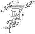
- FIG. 1 is a block diagram of an X-ray diagnostic apparatus and peripheral devices in an embodiment. It is the schematic of the X-ray diagnostic apparatus in embodiment. It is a flowchart in an embodiment. It is a schematic diagram of a screen displayed on a display in an embodiment. It is a key map of distribution contents information in an embodiment. It is a schematic diagram of a screen displayed on a display in an embodiment. It is a schematic diagram of a screen displayed on a display in an embodiment. It is the schematic of the test room and operation room in a modification.
- an X-ray diagnostic apparatus as a medical information distribution system will be described.
- FIG. 1 is a block diagram of the X-ray diagnostic apparatus and other peripheral devices in the present embodiment
- FIG. 2 is a schematic diagram of the X-ray diagnostic apparatus in the present embodiment.
- the configuration surrounded by dotted line A, dotted line B, and dotted line C in FIG. 1 indicates the configuration provided in the examination room, the operation room, and the machine room, respectively.
- the X-ray diagnostic apparatus 1 in this embodiment includes a system control unit 2, an X-ray control unit 3, an X-ray irradiation unit 4, a C arm 5, an X-ray detection unit 6, and image processing.
- X-ray irradiation unit 4 C-arm 5, X-ray detection unit 6, bed 10, operation unit 11a, rail 14a, rail 14b, rail 15a, rail 15b, base unit 16, column unit 17, and C-arm support unit 18 are Provided in the examination room. Further, the system control unit 2, the X-ray control unit 3, the image processing unit 7, the storage unit 8, the operation mechanism control unit 9, the medical information input / output unit 12, and the medical information distribution control unit 13 are provided in the machine room. Furthermore, the operation unit 11b is provided in the operation room.
- the system control unit 2 instructs the X-ray control unit 3 in accordance with an operator instruction via the operation unit 11a or the operation unit 11b.
- the system control unit 2 inputs the medical image stored in the storage unit 8 to the medical information input / output unit 12.
- the system control unit 2 generates a predetermined operation screen at a predetermined timing and inputs it to the medical information input / output unit 12.
- the system control unit 2 inputs X-ray irradiation information to the medical information input / output unit 12 when instructing X-ray irradiation to the X-ray control unit 3 in accordance with an instruction from the operator via the operation unit 11a or the operation unit 11b.
- the system control unit 2 instructs the X-ray control unit 3 to stop the X-ray irradiation in accordance with an instruction from the operator via the operation unit 11a or the operation unit 11b
- the medical information input / output is performed so as to stop the delivery of the X-ray irradiation information.
- the unit 12 is instructed.
- the system control unit 2 instructs the operation mechanism control unit 9 in accordance with an operator instruction via the operation unit 11a or the operation unit 11b.
- the X-ray control unit 3 includes a high voltage generation unit, and applies a voltage to the X-ray tube of the X-ray irradiation unit 4 in accordance with an instruction from the system control unit 2.
- the X-ray control unit 3 stops the voltage applied to the X-ray irradiation unit 4 according to the instruction from the system control unit 2.
- the X-ray irradiation unit 4 has an X-ray tube and an X-ray diaphragm.
- the X-ray tube emits X-rays when applied from the high voltage generation unit of the X-ray control unit 3.
- the X-ray diaphragm adjusts the irradiation range of X-rays emitted from the X-ray tube according to instructions from the operation mechanism control unit 9.
- the X-ray detection unit 6 detects X-rays transmitted from the patient P irradiated from the X-ray irradiation unit 4 and placed on the bed 10. The X-ray detection unit 6 generates a detection signal based on the detected X-ray and transmits the generated detection signal to the image processing unit 7.
- the image processing unit 7 generates medical image data based on the detection signal received from the X-ray detection unit 6.
- the medical image data is, for example, X-ray fluoroscopic image data or road map image data.
- the image processing unit 7 transmits the generated X-ray fluoroscopic image data and road map image data to the storage unit 8.
- the storage unit 8 stores medical image data received from the image processing unit 7.
- the storage unit 8 inputs the stored medical image data to the medical information input / output unit 12 in accordance with an instruction from the system control unit 2.
- the rail 14a and the rail 14b are supported, for example, on the ceiling of the examination room, and move the rail 15a and the rail 15b in the direction of arrow D in FIG. 2 in accordance with an instruction from the operation mechanism control unit 9.
- the rail 15a and the rail 15b move the base unit 16 in the direction of arrow E in FIG. 2 according to an instruction from the operation mechanism control unit 9.
- the base unit 16 rotates the support column 17 in the direction of arrow F in FIG. 2 in accordance with an instruction from the operation mechanism control unit 9.
- the column 17 rotates the C-arm support 18 in the direction of arrow G in FIG. 2 in accordance with an instruction from the operation mechanism controller 9.
- the C arm support unit 18 slides the C arm 5 in the direction of arrow H in FIG. 2 in accordance with an instruction from the operation mechanism control unit 9.
- the C-arm 5 holds the X-ray irradiation unit 4 and the X-ray detection unit 6 at the ends so that they face each other.
- the operation mechanism control unit 9 controls the operation of the aforementioned X-ray diaphragm in accordance with an instruction from the system control unit 2 and controls the X-ray irradiation range.
- the operation mechanism control unit 9 instructs the operations of the rail 14a, rail 14b, rail 15a, rail 15b, base unit 16, column 17 and C-arm support unit 18 in accordance with instructions from the system control unit 2, and X-ray
- the positions and angles of the irradiation unit 4 and the X-ray detection unit 6 are changed.
- the operation mechanism control unit 9 instructs the operation of the bed 10 according to the instruction from the system control unit 2 and moves the position of the patient P placed on the bed 10.
- the bed 10 places the patient P, and moves the position of the patient P in the directions of arrows I and J in FIG. 2, for example, in accordance with an instruction from the operation mechanism control unit 9.
- the operation unit 11a includes, for example, a lever and a switch, and the operator gives an X-ray irradiation instruction, an X-ray irradiation stop instruction, and an instruction to the operation mechanism control unit 9 to the system control unit 2 via the operation unit 11a.
- the operation unit 11b includes, for example, a lever, a switch, a mouse, and a keyboard. An operator instructs the X-ray irradiation, the X-ray irradiation stop, the operation mechanism control unit 9, and the operation room via the operation unit 11b.
- the system control unit 2 is instructed to a predetermined operation screen displayed on the display.
- the electroencephalograph 21 is a peripheral device and measures the electroencephalogram of the patient P.
- the electroencephalograph 21 inputs the measured electroencephalogram to the medical information input / output unit 12 as biological wave information.
- the ventilator 22 is a peripheral device and measures the respiratory wave of the patient P.
- the ventilator 22 inputs the measured respiratory wave to the medical information input / output unit 12 as biological wave information.
- the anesthesia machine 23 is a peripheral device.
- the anesthetic gas used for the patient P is input to the medical information input / output unit 12 as peripheral device information.
- the optical camera 24 is a peripheral device, and for example, captures the state of an incision in the operation of the patient P, and generates camera image data.
- the optical camera 24 inputs the generated camera image data to the medical information input / output unit 12.
- the neurological function testing device 25 is a peripheral device and measures the electrocardiogram waveform of the patient P.
- the neurological function testing device 25 inputs the measured electrocardiogram waveform to the medical information input / output unit 12 as biological wave information.
- the ultrasonic diagnostic apparatus 26 is a peripheral device, and generates ultrasonic diagnostic image data of the patient P.
- the ultrasonic diagnostic apparatus 26 inputs the generated ultrasonic diagnostic image data to the medical information input / output unit 12 as peripheral device information.
- the examination room display 31 is provided in the examination room as one of output destinations.
- the laboratory display 31 has display means and displays medical information output from the medical information input / output unit 12 and distributed.
- the operation room display 32 is provided in the operation room as one of output destinations.
- the operation room display 32 has display means and displays medical information output from the medical information input / output unit 12 and distributed.
- the biological wave information monitor 33 is provided in the examination room as one of output destinations.
- the biological wave information monitor 33 has display means and displays the medical information output from the medical information input / output unit 12 and distributed.
- the display device 34 is, for example, a tablet terminal that can communicate with the X-ray diagnostic apparatus wirelessly or by wire, and is a user interface having input means and display means.
- the display 34 is carried by a medical worker in an examination room or an operation room as one of output destinations. In the present embodiment, for example, a case where a medical worker who uses the display 34 is a nurse will be described below.
- the display device 34 registers role information according to the input of the medical staff through the input means.
- the display device 34 notifies the registered role information to the medical information distribution control unit 13.
- the display 34 displays the medical information output from the medical information input / output unit 12 and distributed. Details of the role information will be described later.
- the medical information input / output unit 12 receives medical information from the X-ray diagnostic apparatus 1 such as the system control unit 2 and the storage unit 8. Further, the medical information input / output unit 12 receives medical information from the outside of the X-ray diagnostic apparatus 1 such as an electroencephalograph 21, a ventilator 22, an anesthesia machine 23, an optical camera 24, a nerve function testing apparatus 25, and an ultrasonic diagnostic apparatus 26, for example. Is entered. Further, the medical information input / output unit 12, for example, with respect to the outside of the laboratory display 31, the operation room display 32, the biological wave information monitor 33, the display 34, etc., in accordance with an instruction from the medical information distribution control unit 13. The input medical information is output.
- the medical information distribution control unit 13 outputs medical information to be output to the examination room display 31, the operation room display 32, and the biological wave information monitor 33 based on preset information registered in advance as registration information.
- the input / output unit 12 is instructed.
- the preset information is information for determining medical information to be output to the medical information input / output unit 12 for the examination room display 31, the operation room display 32, and the biological wave information monitor 33.
- the medical information distribution control unit 13 receives X-ray irradiation information input from the system control unit 2, X-ray fluoroscopic image data and road map image data input from the storage unit 8, an electroencephalograph 21, an artificial brain
- the laboratory display 31 includes the biological wave information input from the respiratory device 22 and the nerve function testing device 25, the peripheral device information input from the anesthesia device 23 and the ultrasonic diagnostic device 26, and the camera image data input from the optical camera 24.
- the medical information distribution control unit 13 receives the X-ray irradiation information input from the system control unit 2, the road map image data input from the storage unit 8, and the camera image data input from the optical camera 24.
- the medical information input / output unit 12 is instructed to output to the operation room display 32.
- the medical information distribution control unit 13 is configured to output medical wave information input from, for example, the electroencephalograph 21, the ventilator 22, and the nerve function testing device 25 to the biological wave information monitor 33.
- the information input / output unit 12 is instructed.
- the medical information distribution control unit 13 registers the distribution content information based on the role information notified from the display device 34.
- the medical information distribution control unit 13 instructs the medical information input / output unit 12 on the medical information that the medical information input / output unit 12 outputs to the display device 34 based on the distribution content information registered as registration information. Details of the distribution content information will be described later.
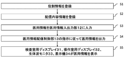
- FIG. 3 is a flowchart showing a flow of input / output of medical information to the medical information input / output unit 12 of the present embodiment. Steps S1 and S2 shown in FIG. 3 show the flow before the start of the inspection, and steps after step S3 show the flow after the start of the inspection.
- step S1 the nurse who uses the display device 34 activates the display device 34 and registers role information.
- FIG. 4 is a schematic diagram of a screen displayed on the display means of the display device 34 when the display device 34 is activated, for example.
- the screen of the display means of the display device 34 at this time includes a role information column 41.
- the role information column 41 includes, for example, a surgical assistant preparation staff, a surgical assistant technique staff, a surgical assistant direct support staff, an IVR (interventional radiology) assistant direct support staff, an IVR assistant technique staff, an IVR assistant staff staff, A plurality of role information such as an operation room assistant is provided.
- the preparation staff of the surgical assistant has a role of preparing a medical device such as a scalpel and a medicine to be used, for example.
- the surgical assistant is in charge of supporting the surgical operation using, for example, an anesthesia machine.
- the direct support charge of the surgical assistant is a role of handing a medical device such as a scalpel to a surgeon, for example.
- the direct support staff of the assistant IVR is a role of handing a medical device such as a catheter to a doctor in charge of the IVR, for example.
- the procedure for assistant IVR is a role of supporting the IVR procedure using, for example, an ultrasonic diagnostic apparatus.
- the IVR assistant preparation staff is responsible for preparing medical devices such as catheters and drugs to be used.
- the operation room assistant plays a role in supporting the entire surgical operation and IVR procedure in the operation room.
- the nurse who uses the display device 34 selects role information corresponding to his / her role via the input means of the display device 34.
- role information is selected by the nurse using the display device 34
- the display device 34 registers and registers the selected role information as role information corresponding to the role of the nurse using the display device 34.
- the role information is notified to the medical information distribution control unit 13.
- step S2 when the role information is notified, the medical information distribution control unit 13 registers the distribution content information.
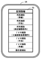
- FIG. 5 is a schematic diagram of a distribution content setting table 51 used for convenience to explain registration of distribution content information.
- the medical information distribution control unit 13 registers distribution content information corresponding to the display device 34 based on, for example, the distribution content setting table 51 and role information notified from the display device 34.
- the medical information distribution control unit 13 uses X-ray irradiation information, camera image data information, biological information as distribution content information corresponding to the display device 34.
- Register wave information This is because nurses who have the role of preparing surgical assistants need camera images that can check the progress of surgery for the preparation of surgical instruments such as scalpels, and prepare drugs that match the patient's condition. This is because the biological wave information is necessary to do so, and the X-ray irradiation information is necessary to avoid exposure by X-ray as much as possible.
- the delivery content includes information on the type, display size, and display position of medical information in addition to medical information such as X-ray irradiation information, camera image data information, and biological information, which will be described later.
- medical information such as X-ray irradiation information, camera image data information, and biological information, which will be described later.
- information regarding the type, display size, and display position of medical information may be set in advance according to role information (including operator information and operator position information).
- peripheral device information and biological wave information are registered as distribution content information corresponding to the display device 34. This is because nurses who have the role of surgical assistants need peripheral device information to know the state of peripheral devices they use, for example, and biowave information to know the state of patients during surgery Due to the need.
- X-ray irradiation information and biological wave information are registered as distribution content information corresponding to the display device 34. This is because nurses who are in charge of direct support for surgical assistants need X-ray irradiation information to avoid exposure to X-rays as much as possible, and bio wave information is necessary to know the patient's condition during surgery. Due to the fact that
- the role information notified from the display device 34 is the direct support charge of the assistant IVR
- X-ray irradiation information, camera image data, and road map image data are registered as distribution content information corresponding to the display device 34.
- nurses who are in charge of direct support of assistant IVR need X-ray irradiation information to avoid exposure by X-ray as much as possible, and camera image data is used to pass a catheter used for IVR to a doctor. This is due to the need for road map image data.
- X-ray irradiation information when the role information notified from the display device 34 is a person in charge of the assistant IVR procedure, X-ray irradiation information, X-ray fluoroscopic image data, peripheral device information, and biological wave information are distributed as distribution content information corresponding to the display device 34. sign up. This is because nurses with the role of assistant IVR procedures need X-ray irradiation information to avoid exposure to X-rays as much as possible, and X-ray fluoroscopic image data is necessary to observe the procedure. This is because the peripheral device information is necessary to know the state of the peripheral device used by the user, and the biological wave information is necessary to know the state of the patient during the operation.
- X-ray irradiation information X-ray fluoroscopic image data
- camera image data information are registered as distribution content information corresponding to the display device 34.
- nurses who are responsible for preparing IVR assistants need X-ray irradiation information in order to avoid X-ray exposure as much as possible, and prepare equipment and chemicals to be used as the procedure progresses.
- X-ray fluoroscopic image data capable of observing the state of the procedure is necessary, and since it is located away from the patient, camera image data that can confirm the progress of the surgical operation is necessary.
- X-ray irradiation information, camera image data, and road map image data are registered as distribution content information corresponding to the display device 34. This is because a nurse having the role of an operation room assistant needs, for example, X-ray irradiation information, camera image data, and road map image data in order to know a rough situation in the examination room. .
- step S3 when the examination is started, various medical information is input to the medical information input / output unit 12.
- step S4 the medical information distribution control unit 13 outputs the medical information output from the medical information input / output unit 12 to the display 34 based on the preset information registered in advance and the distribution content information registered in step S2. Information is instructed to the medical information input / output unit 12.
- the medical information input / output unit 12 performs X-ray irradiation input from the system control unit 2 in accordance with an instruction from the medical information distribution control unit 13.
- the information, the camera image data input from the optical camera 24, the electroencephalograph 21, the ventilator 22, and the biological wave information input from the nerve function testing device 25 are output to the display 34.
- the medical information input / output unit 12 is input from the anesthesia machine 23 and the ultrasonic diagnostic apparatus 26 in accordance with instructions from the medical information distribution control unit 13.
- the peripheral information, the electroencephalograph 21, the ventilator 22, and the biological wave information input from the nerve function testing device 25 are output to the display device 34.
- the medical information input / output unit 12 performs X-rays input from the system control unit 2 in accordance with instructions from the medical information distribution control unit 13.
- the irradiation information, the electroencephalogram 21, the ventilator 22, and the biological wave information input from the nerve function testing device 25 are output to the display 34.
- the medical information input / output unit 12 performs the X-ray irradiation input from the system control unit 2 in accordance with an instruction from the medical information distribution control unit 13.
- Information, road map image data input from the storage unit 8, and camera image data input from the optical camera 24 are output to the display 34.
- the medical information input / output unit 12 performs the X-ray irradiation input from the system control unit 2 in accordance with an instruction from the medical information distribution control unit 13.
- the medical information input / output unit 12 performs X-ray irradiation input from the system control unit 2 in accordance with an instruction from the medical information distribution control unit 13.
- Information, X-ray fluoroscopic image data input from the storage unit 8, and camera image data input from the optical camera 24 are output to the display 34.
- the medical information input / output unit 12 performs the X-ray irradiation information input from the system control unit 2 according to instructions from the medical information distribution control unit 13,
- the road map image data input from the storage unit 8 and the camera image data input from the optical camera 24 are output to the display 34.
- the medical information input / output unit 12 in accordance with an instruction from the medical information distribution control unit 13, X-ray irradiation information input from the system control unit 2, X-ray fluoroscopic image data input from the storage unit 8, and road map Image data, electroencephalograph 21, ventilator 22, biological wave information input from neurological function testing device 25, anesthesia device 23, peripheral device information input from ultrasonic diagnostic device 26, camera input from optical camera 24
- the image data is output to the examination room display 31.
- the medical information input / output unit 12 receives X-ray irradiation information input from the system control unit 2 according to an instruction from the medical information distribution control unit 13, road map image data input from the storage unit 8, and from the optical camera 24.
- the input camera image data is output to the operation room display 32.
- the medical information input / output unit 12 outputs the biological wave information input from the electroencephalograph 21, the ventilator 22, and the nerve function testing device 25 to the biological wave information monitor 33 in accordance with an instruction from the medical information distribution control unit 13. To do.
- step S5 the laboratory display 31, the operation room display 32, the biological wave information monitor 33, and the display 34 display the medical information output to each.
- 6A and 6B are schematic diagrams of screens displayed on the display means of the display device 34 when the medical information is output from the medical information input / output unit 12.
- the role of the nurse who uses the display device 34 is in charge of preparing a surgical assistant.
- FIG. 6A When medical information is output from the medical information input / output unit 12, a screen as shown in FIG. 6A is first displayed.
- the screen shown in FIG. 6A includes a medical information selection button 42 corresponding to the type of medical information output from the medical information input / output unit 12 to the display device 34.
- medical information selection buttons 42 respectively corresponding to X-ray irradiation information, camera image data, and biological wave information are displayed on the display means of the display 34.
- the nurse who uses the display device 34 selects the medical information selection button 42 displayed on the display means of the display device 34 via the input means of the display device 34.
- the screen of the display device 34 is changed to a screen as shown in FIG.
- the medical information input button corresponding to the medical information selection button 42 is displayed.
- the medical information output from the output unit 12 to the display device 34 is displayed in the medical information display field 43.
- the screen is switched to a screen as shown in FIG. 6A, and other medical information can be referred to.
- the X-ray diagnostic apparatus 1 collectively manages medical information generated by the X-ray diagnostic apparatus 1 itself and peripheral devices using the medical information input / output 12, and the medical information distribution control unit 13 Output to a predetermined output destination according to the instruction.
- the desired medical information is displayed on the display device 34.
- Information can be displayed and referenced. Further, for example, a medical worker using the display 34 is working away from the laboratory display 31, the operation room display 32, and the biological wave information monitor 33, and is blocked by another medical worker or medical device.
- the desired medical information displayed on the examination room display 31 When it is difficult to confirm the desired medical information displayed on the examination room display 31, the operation room display 32, and the biological wave information monitor 33, the desired medical information is displayed on the display 34 for reference. Can do. In general, even in a situation where a plurality of medical workers are mixed, appropriate medical information can be confirmed for each medical worker.
- role information corresponding to the roles of other medical workers such as a surgeon, surgeon support doctor, IVR doctor, and IVR support doctor may be added to the role information.
- medical image data such as an X-ray CT image or an MRI image stored in PACS (Picture Archiving and Communication System) may be acquired, and the medical image data may be added to the distribution content information.
- image supplementary information such as patient ID, name, date of birth, etc. may be acquired from HIS (Hospital Information System) or RIS (Radiology Information System), and the image supplementary information may be added to the delivery content information.
- the present embodiment a case has been described in which there is one display device 34 and is used by one medical worker, but there may be a plurality of display devices 34 which may be used by a plurality of medical workers.
- the display device 34 when all the medical personnel in the examination room or the operation room are allowed to use the display device 34, the information that overlaps the medical information displayed on the display device 34 is displayed in the examination room display 31, the operation room display 32, It is not always necessary to display on the biological wave information monitor 33, whereby the laboratory display 31, the operation room display 32, the biological wave information monitor 33, and the like can be reduced in size.
- the space vacated by downsizing such as the examination room display 31, the operation room display 32, and the biological wave information monitor 33 can be used for another purpose.
- the diagnostic device 1 may acquire and the role may be automatically set depending on the position of the display 34 in the examination room or the operation room. Thereby, a medical worker who uses the display device 34 can refer to medical information corresponding to the place.
- FIG. 7 is a schematic diagram of the examination room A and the operation room B.
- the examination room A1 (area surrounded by a dotted line A in FIG. 1) has an area D, an area E, an area F, an area G, an area H, and an area I surrounded by a dotted line.
- the operation room B1 (area surrounded by a dotted line B in FIG. 1) has an area J.
- the display device 34 when the display device 34 is located in the area D, the role of a medical worker who uses the display device 34 is set to a person in charge of preparing a surgical assistant.
- the display device 34 is located in the area E, the role of the medical worker who uses the display device 34 is set to the surgical assistant procedure.
- the role of the medical worker who uses the display device 34 is set to the direct support staff of the surgical assistant.
- the role of the medical worker who uses the display device 34 is set to the direct support staff of the assistant IVR.
- the role of the medical worker who uses the display device 34 is set to the procedure staff of the assistant IVR.
- the role of the medical worker who uses the display device 34 is set to the IVR assistant preparation staff.
- the display device 34 is located in the area J, the role of the medical worker who uses the display device 34 is set to the operation room assistant.
- a stand capable of installing the display device 34 is provided in each of the area D, the area E, the area F, the area G, the area H and the area I.
- the specification may be such that role information corresponding to the area is registered in the medical information distribution control unit 13 as role information of the display device 34.
- the delivery content information corresponding to the role information is fixed regardless of the progress status of the surgical operation or the IVR procedure has been described.
- the role information is automatically changed to the role information depending on the progress status of the surgical operation or the IVR procedure.
- the corresponding distribution content information may be changed (updated). Thereby, the medical information desired by the medical staff who uses the display device 34 can be distributed more.
- the distribution content information corresponding to the role information is automatically changed (updated) based on the state of the subject, and the display contents of the displays 31, 32, the monitor 33, the display device 34, etc. are changed (updated).
- the state of the subject refers to a biological state of the subject, for example, a heartbeat state, an oxygen concentration, a blood pressure state of the subject accompanying the start of blood transfusion, and a blood pressure state of the subject accompanying the start of heart-lung machine.
- the case where a medical worker using the display device 34 registers role information has been described.
- the operator of the X-ray diagnostic apparatus 1 registers role information via the operation unit 11b. May be.
- the correspondence relationship between the role information and the distribution content information may be registered.
- the distribution content setting table 51 is displayed on the operation room display, and the operator inputs the distribution content setting table 51 via the operation unit 11b.
- the role information and the distribution content information include, for example, the examination room display 31, the operation room display 32, the installation position of the biological wave information monitor 33, the examination room display 31, the operation room display 32, and the biological wave information monitor 33. Determined based on health care workers referring to.
- role information and distribution content information are registered through the operation unit 11b of the X-ray diagnostic apparatus 1 as described above.
- the display 34 displays the medical information one by one on the screen as shown in FIG. 6B
- the screen may be divided and a plurality of medical information may be displayed simultaneously.
- a medical worker who uses the display device 34 can refer to a plurality of pieces of medical information without operating the display device 34, and can save time and effort.
- the medical information from the peripheral device is directly input to the medical information input / output unit 12 .
- the medical information input / output unit 12 is indirectly stored via the storage in the storage unit 8. May be entered.
- the X-ray diagnostic apparatus 1 includes the medical information input / output unit 12 and the medical information distribution control unit 13 .
- the medical information input / output unit 12 and the medical information distribution control unit 13 are independent, An information distribution apparatus may be used.
- the medical information distribution apparatus by connecting the medical information distribution apparatus to an X-ray diagnosis apparatus that does not include the medical information input / output unit 12 and the medical information distribution control unit 13, the same effect as that of the X-ray diagnosis apparatus 1 described in the present embodiment. Can be fulfilled.
- the X-ray diagnostic apparatus 1 has been described as an example including the medical information input / output unit 12 and the medical information distribution control unit 13 constituting the medical information distribution system. It may be an ultrasonic diagnostic apparatus.
Abstract
医用従事者ごとに適切な医用情報を確認できるようにするために、実施形態の医用情報配信システムは、医用装置あるいは周辺機器からの複数の医用情報を、前記医用装置の表示部または表示手段を有する複数の装置へ表示する表示制御部と、前記複数の医用情報のうち、前記医用装置および前記複数の装置の有する識別情報に基づいて表示内容を設定する表示内容設定部と、設定された前記複数の医用情報の表示内容を前記表示部および前記複数の装置へ送信する情報送信部とを備える。
Description
本発明の実施形態は、医用情報配信システムに関する。
通常のカテーテル手技に加えて外科手術を並行して実施するHybrd Approachと呼ばれる手技体系がある。このHybrid Approachが実施される検査室や操作室には、例えば複数の画面に分割された大型ディスプレイや複数の小型ディスプレイが設置されており、これらの画面にはX線診断装置によって生成されるX線透視画像、造影剤によって血管が強調されたX線画像(ロードマップ画像)、切開部の様子を光学カメラで撮影したカメラ画像、心電図波形や呼吸波形、脳波形などの生体波情報、X線診断装置でX線が発生しているか否かを示すX線照射情報、X線診断装置の周辺に位置する超音波診断装置で生成された超音波画像や麻酔器などの動作を示す周辺機器情報、といった様々な医用情報が表示される。
一方、Hybrid Approachでは、例えばカテーテル手技担当者、外科手術担当者、麻酔担当者、生体波情報観察担当者、看護スタッフといった様々な医療従事者が検査室や操作室に混在し、各々の役割に沿った作業を行う。
上記のような場合、例えばある医療従事者にとってはディスプレイに表示させたい医用情報が、他の医療従事者にとっての所望の医用情報とは異なる可能性がある。あるいは、例えばディスプレイから離れて作業する医療従事者は、別の医療従事者に遮られてディスプレイに表示された医用情報を確認することが困難である可能性がある。
本発明が解決しようとする課題は、医用従事者ごとに適切な医用情報を確認できるようにすることである。
上記課題を解決するために、実施形態の医用情報配信システムは、医用装置あるいは周辺機器からの複数の医用情報を、前記医用装置の表示部または表示手段を有する複数の装置へ表示する表示制御部と、前記複数の医用情報のうち、前記医用装置および前記複数の装置の有する識別情報に基づいて表示内容を設定する表示内容設定部と、設定された前記複数の医用情報の表示内容を前記表示部および前記複数の装置へ送信する情報送信部とを備える。
以下、本発明の実施形態について図面を参照しながら説明する。
本実施形態は、医用情報配信システムとしてのX線診断装置について説明する。まず、図1と図2を用いて本実施形態におけるX線診断装置1とその他の周辺機器の構成および関係を説明する。
図1は、本実施形態におけるX線診断装置とその他の周辺機器のブロック図であり、図2は本実施形態におけるX線診断装置の概略図である。図1における点線A、点線B、点線Cで囲まれた構成は、それぞれ検査室、操作室、機械室に設けられる構成を示す。
図1又は図2に示すように、本実施形態におけるX線診断装置1は、システム制御部2、X線制御部3、X線照射部4、Cアーム5、X線検出部6、画像処理部7、記憶部8、動作機構制御部9、寝台10、操作部11a、操作部11b、医用情報入出力部12、医用情報配信制御部13、レール14a、レール14b、レール15a、レール15b、基台部16、支柱部17、Cアーム支持部18を備える。X線照射部4、Cアーム5、X線検出部6、寝台10、操作部11a、レール14a、レール14b、レール15a、レール15b、基台部16、支柱部17、Cアーム支持部18は検査室に設けられる。また、システム制御部2、X線制御部3、画像処理部7、記憶部8、動作機構制御部9、医用情報入出力部12、医用情報配信制御部13は機械室に設けられる。更に、操作部11bは操作室に設けられる。
システム制御部2は、操作部11aあるいは操作部11bを介したオペレータの指示に従って、X線制御部3に指示する。システム制御部2は、記憶部8に記憶された医用画像を医用情報入出力部12に入力する。システム制御部2は、所定のタイミングにおいて所定の操作画面を生成し、医用情報入出力部12に入力する。システム制御部2は、操作部11aあるいは操作部11bを介したオペレータの指示に従ってX線制御部3にX線照射を指示すると、X線照射情報を医用情報入出力部12に入力する。システム制御部2は、操作部11aあるいは操作部11bを介したオペレータの指示に従ってX線制御部3にX線照射の停止を指示すると、X線照射情報の配信を停止するように医用情報入出力部12に指示する。本実施形態において、システム制御部2は、操作部11aあるいは操作部11bを介したオペレータの指示に従って、動作機構制御部9に指示する。
X線制御部3は、高電圧発生部を備えており、システム制御部2からの指示に従って、X線照射部4が有するX線管に電圧を印加させる。X線制御部3は、システム制御部2からの指示に従って、X線照射部4に印加していた電圧を停止させる。
X線照射部4は、X線管とX線絞りを有する。X線管は、X線制御部3の高電圧発生部から印加されるとX線を照射する。X線絞りは、動作機構制御部9からの指示に従って、X線管から照射されたX線の照射範囲を調整する。
X線検出部6は、X線照射部4から照射され寝台10に載置された患者Pを透過したX線を検出する。X線検出部6は、検出したX線に基づく検出信号を生成し、生成した検出信号を画像処理部7に送信する。
画像処理部7は、X線検出部6から受信した検出信号に基づいて医用画像データを生成する。ここで医用画像データは、例えば、X線透視画像データやロードマップ画像データである。画像処理部7は、例えば、生成したX線透視画像データとロードマップ画像データを記憶部8に送信する。
記憶部8は、画像処理部7から受信した医用画像データを記憶する。記憶部8は、システム制御部2からの指示に従って、記憶した医用画像データを医用情報入出力部12に入力する。
レール14a、レール14bは、例えば検査室天井に支持されており、動作機構制御部9からの指示に従って、レール15a、レール15bを図2における矢印Dの方向に移動させる。レール15a、レール15bは、動作機構制御部9からの指示に従って、基台部16を図2における矢印Eの方向に移動させる。基台部16は、動作機構制御部9からの指示に従って、支柱部17を図2における矢印Fの方向に回動させる。支柱部17は、動作機構制御部9からの指示に従って、Cアーム支持部18を図2における矢印Gの方向に回動させる。Cアーム支持部18は、動作機構制御部9からの指示に従って、Cアーム5を図2における矢印Hの方向にスライドさせる。Cアーム5は、X線照射部4とX線検出部6が対向するようにそれぞれを端部に保持する。
動作機構制御部9は、システム制御部2からの指示に従って、前述のX線絞りの動作を制御し、X線の照射範囲を制御する。動作機構制御部9は、システム制御部2からの指示に従って、レール14a、レール14b、レール15a、レール15b、基台部16、支柱部17、Cアーム支持部18の動作を指示し、X線照射部4およびX線検出部6の位置や角度を変更させる。動作機構制御部9は、システム制御部2からの指示に従って、寝台10の動作を指示し、寝台10に載置された患者Pの位置を移動させる。
寝台10は、患者Pを載置させ、動作機構制御部9からの指示に従って、患者Pの位置を例えば図2における矢印I、Jの方向に移動させる。
操作部11aは、例えばレバーやスイッチを備え、オペレータは操作部11aを介して、X線の照射指示、X線の照射の停止指示、動作機構制御部9への指示、をシステム制御部2に対して行う。操作部11bは、例えばレバーやスイッチ、マウスやキーボードを備え、オペレータは操作部11bを介して、X線の照射指示、X線の照射の停止指示、動作機構制御部9への指示、操作室用ディスプレイに表示される所定の操作画面への指示をシステム制御部2に対して行う。
脳波計21は、周辺機器であり、患者Pの脳波を計測する。脳波計21は、計測した脳波を生体波情報として医用情報入出力部12に入力する。
人工呼吸器22は、周辺機器であり、患者Pの呼吸波を計測する。人工呼吸器22は、計測した呼吸波を生体波情報として医用情報入出力部12に入力する。
麻酔器23は、周辺機器であり、例えば患者Pに対して使用している麻酔ガスの使用量を周辺機器情報として医用情報入出力部12に入力する。
光学カメラ24は、周辺機器であり、例えば患者Pの手術における切開部の様子を撮影し、カメラ画像データを生成する。光学カメラ24は、生成したカメラ画像データを医用情報入出力部12に入力する。
神経機能検査装置25は、周辺機器であり、患者Pの心電図波形を計測する。神経機能検査装置25は、計測した心電図波形を生体波情報として医用情報入出力部12に入力する。
超音波診断装置26は、周辺機器であり、患者Pの超音波診断画像データを生成する。超音波診断装置26は、生成した超音波診断画像データを周辺機器情報として医用情報入出力部12に入力する。
検査室用ディスプレイ31は、出力先の一つとして検査室に設けられる。検査室用ディスプレイ31は、表示手段を有し、医用情報入出力部12から出力され配信された医用情報を表示する。
操作室用ディスプレイ32は、出力先の一つとして操作室に設けられる。操作室用ディスプレイ32は、表示手段を有し、医用情報入出力部12から出力され配信された医用情報を表示する。
生体波情報モニタ33は、出力先の一つとして検査室に設けられる。生体波情報モニタ33は、表示手段を有し、医用情報入出力部12から出力され配信された医用情報を表示する。
表示機34は、例えばX線診断装置と無線あるいは有線で通信可能なタブレット端末であり、入力手段と表示手段を有するユーザインターフェイスである。表示機34は、出力先の一つとして検査室あるいは操作室内の医療従事者によって持ち運びされる。本実施形態において、例えば表示機34を使用する医療従事者が看護師である場合を仮定し、以下説明する。表示機34は、当該入力手段を介した医療従事者の入力に従って、役割情報を登録する。表示機34は、登録された役割情報を医用情報配信制御部13に通知する。表示機34は、医用情報入出力部12から出力され配信された医用情報を表示する。なお、役割情報の詳細については後述する。
医用情報入出力部12は、例えばシステム制御部2、記憶部8といったX線診断装置1の内部から医用情報が入力される。また、医用情報入出力部12は、例えば脳波計21、人工呼吸器22、麻酔器23、光学カメラ24、神経機能検査装置25、超音波診断装置26といったX線診断装置1の外部から医用情報が入力される。更に、医用情報入出力部12は、医用情報配信制御部13からの指示に従って、例えば検査室用ディスプレイ31、操作室用ディスプレイ32、生体波情報モニタ33、表示機34などの外部に対して、入力された医用情報を出力する。
医用情報配信制御部13は、予め登録情報として登録されているプリセット情報に基づいて、検査室用ディスプレイ31、操作室用ディスプレイ32、生体波情報モニタ33に対して出力する医用情報を、医用情報入出力部12に指示する。プリセット情報は、検査室用ディスプレイ31、操作室用ディスプレイ32、生体波情報モニタ33に対して医用情報入出力部12に出力させる医用情報を決める情報である。医用情報配信制御部13は、プリセット情報に基づいて、システム制御部2から入力されたX線照射情報、記憶部8から入力されたX線透視画像データとロードマップ画像データ、脳波計21、人工呼吸器22、神経機能検査装置25から入力された生体波情報、麻酔器23、超音波診断装置26から入力された周辺機器情報、光学カメラ24から入力されたカメラ画像データを検査室用ディスプレイ31に出力するように、医用情報入出力部12に対して指示する。医用情報配信制御部13は、プリセット情報に基づいて、システム制御部2から入力されたX線照射情報、記憶部8から入力されたロードマップ画像データ、光学カメラ24から入力されたカメラ画像データを操作室用ディスプレイ32に出力するように、医用情報入出力部12に対して指示する。医用情報配信制御部13は、プリセット情報に基づいて、例えば、脳波計21、人工呼吸器22、神経機能検査装置25から入力された生体波情報を生体波情報モニタ33に出力するように、医用情報入出力部12に対して指示する。
また、医用情報配信制御部13は、表示機34から通知される役割情報に基づいて、配信内容情報を登録する。医用情報配信制御部13は、登録情報として登録された配信内容情報に基づいて、医用情報入出力部12が表示機34に対して出力する医用情報を、医用情報入出力部12に指示する。配信内容情報についての詳細は後述する。
次に、本実施形態の医用情報入出力部12への医用情報の入出力の流れを、図3乃至図6のいずれかを用いて説明する。
図3は、本実施形態の医用情報入出力部12への医用情報の入出力の流れを示すフロー図である。なお図3に示すステップS1およびステップS2は検査開始前の時点のフローを示し、ステップS3以降は検査開始後のフローを示す。
ステップS1において、表示機34を使用する看護師は、表示機34を起動させ、役割情報を登録する。
図4は、例えば表示機34の起動時において、表示機34の表示手段に表示される画面の概略図である。図4に示すように、このときの表示機34の表示手段の画面は、役割情報欄41を備える。役割情報欄41は、例えば、外科補佐の準備担当、外科補佐の手技担当、外科補佐の直接支援担当、IVR(Interventional Radiology)補佐の直接支援担当、IVR補佐の手技担当、IVR補佐の準備担当、操作室補佐、といったように複数の役割情報を備える。なお、外科補佐の準備担当は、例えば、メスなどの医療機器や使用する薬剤を準備する役割である。外科補佐の手技担当は、例えば麻酔器などを使用して外科手術を支援する役割である。外科補佐の直接支援担当は、例えば外科医師にメスなどの医療機器を手渡す役割である。IVR補佐の直接支援担当は、例えばIVR担当医師にカテーテルなどの医療機器を手渡す役割である。IVR補佐の手技担当は、例えば超音波診断装置などを使用してIVR手技を支援する役割である。IVR補佐の準備担当は、例えばカテーテルなどの医療機器や使用する薬剤を準備する役割である。操作室補佐は、操作室内で外科手術とIVR手技の全体を支援する役割である。
表示機34を使用する看護師は、図4に示すような画面が表示手段に表示されると、表示機34の入力手段を介して、自分に役割に該当する役割情報を選択する。表示機34を使用する看護師によって役割情報が選択されると、表示機34は、選択された役割情報を、表示機34を使用する看護師の役割に該当する役割情報として登録し、登録された役割情報を医用情報配信制御部13に通知する。
ステップS2において、役割情報が通知されると、医用情報配信制御部13は、配信内容情報を登録する。
図5は、配信内容情報の登録を説明するために便宜的に用いる配信内容設定テーブル51の概略図である。医用情報配信制御部13は、例えば配信内容設定テーブル51と、表示機34から通知された役割情報に基づいて、表示機34に対応する配信内容情報を登録する。
例えば、表示機34から通知された役割情報が外科補佐の準備担当である場合、医用情報配信制御部13は、表示機34に対応する配信内容情報としてX線照射情報、カメラ画像データ情報、生体波情報を登録する。これは、外科補佐の準備担当の役割を有する看護師は、例えばメスなどの手術機器の準備のために手術の進み具合を確認できるカメラ画像が必要であり、患者の状態に即した薬剤を準備するために生体波情報が必要であり、X線による被曝を極力避けるためにX線照射情報が必要であることに起因する。
ここで、配信内容は後述するX線照射情報、カメラ画像データ情報、生体情報等の医用情報の他に医用情報の種別、表示サイズ、表示位置に関する情報も含む。なお、役割情報(操作者情報、操作者位置情報を含む)に応じて医用情報の種別、表示サイズ、表示位置に関する情報を予め設定してもよい。
例えば、表示機34から通知された役割情報が外科補佐の手技担当である場合、表示機34に対応する配信内容情報として周辺機器情報、生体波情報を登録する。これは、外科補佐の手技担当の役割を有する看護師は、例えば自分の使用する周辺機器の状態を知るために周辺機器情報が必要であり、手術中の患者の状態を知るために生体波情報が必要であることに起因する。
例えば、表示機34から通知された役割情報が外科補佐の直接支援担当である場合、表示機34に対応する配信内容情報としてX線照射情報、生体波情報を登録する。これは、外科補佐の直接支援担当の役割を有する看護師は、X線による被曝を極力避けるためにX線照射情報が必要であり、手術中の患者の状態を知るために生体波情報が必要であることに起因する。
例えば、表示機34から通知された役割情報がIVR補佐の直接支援担当である場合、表示機34に対応する配信内容情報としてX線照射情報、カメラ画像データ、ロードマップ画像データを登録する。これは、IVR補佐の直接支援担当の役割を有する看護師は、X線による被曝を極力避けるためにX線照射情報が必要であり、IVRに使用するカテーテル等を医師に渡すためにカメラ画像データとロードマップ画像データが必要であることに起因する。
例えば、表示機34から通知された役割情報がIVR補佐の手技担当である場合、表示機34に対応する配信内容情報としてX線照射情報、X線透視画像データ、周辺機器情報、生体波情報を登録する。これは、IVR補佐の手技担当の役割を有する看護師は、X線による被曝を極力避けるためにX線照射情報が必要であり、手技の様子を観察するためにX線透視画像データが必要であり、自分の使用する周辺機器の状態を知るために周辺機器情報が必要であり、手術中の患者の状態を知るために生体波情報が必要であることに起因する。
例えば、表示機34から通知された役割情報がIVR補佐の準備担当である場合、表示機34に対応する配信内容情報としてX線照射情報、X線透視画像データ、カメラ画像データ情報、を登録する。これは、IVR補佐の準備担当の役割を有する看護師は、X線による被曝を極力避けるためにX線照射情報が必要であり、手技の進行に沿って使用する機器や薬液の準備をするために手技の様子を観察できるX線透視画像データが必要であり、患者から離れた位置にいるので外科手術の進行状況を確認できるカメラ画像データが必要であることに起因する。
例えば、表示機34から通知された役割情報が操作室補佐である場合、表示機34に対応する配信内容情報としてX線照射情報、カメラ画像データ、ロードマップ画像データを登録する。これは、操作室補佐の役割を有する看護師は、検査室内で行われている大まかな状況を知るのに、例えばX線照射情報、カメラ画像データ、ロードマップ画像データ必要であることに起因する。
ステップS3において、検査が開始されると、医用情報入出力部12には、様々な医用情報が入力される。
ステップS4において、医用情報配信制御部13は、予め登録されているプリセット情報と、ステップS2において登録された配信内容情報に基づいて、医用情報入出力部12が表示機34に対して出力する医用情報を、医用情報入出力部12に指示する。
例えば、表示機34を使用する看護師が外科補佐の準備担当である場合、医用情報入出力部12は、医用情報配信制御部13からの指示に従って、システム制御部2から入力されたX線照射情報、光学カメラ24から入力されたカメラ画像データ、脳波計21、人工呼吸器22、神経機能検査装置25から入力された生体波情報を、表示機34に対して出力する。
例えば、表示機34を使用する看護師が外科補佐の手技担当である場合、医用情報入出力部12は、医用情報配信制御部13からの指示に従って、麻酔器23、超音波診断装置26から入力された周辺機器情報、脳波計21、人工呼吸器22、神経機能検査装置25から入力された生体波情報を、表示機34に対して出力する。
例えば、表示機34を使用する看護師が外科補佐の直接支援担当である場合、医用情報入出力部12は、医用情報配信制御部13からの指示に従って、システム制御部2から入力されたX線照射情報、脳波計21、人工呼吸器22、神経機能検査装置25から入力された生体波情報を、表示機34に対して出力する。
例えば、表示機34を使用する看護師がIVR補佐の手技担当である場合、医用情報入出力部12は、医用情報配信制御部13からの指示に従って、システム制御部2から入力されたX線照射情報、記憶部8から入力されたロードマップ画像データ、光学カメラ24から入力されたカメラ画像データを、表示機34に対して出力する。
例えば、表示機34を使用する看護師がIVR補佐の手技担当である場合、医用情報入出力部12は、医用情報配信制御部13からの指示に従って、システム制御部2から入力されたX線照射情報、記憶部8から入力されたX線透視画像データ、超音波診断装置26から入力された周辺機器情報、脳波計21、人工呼吸器22、神経機能検査装置25から入力された生体波情報を、表示機34に対して出力する。
例えば、表示機34を使用する看護師がIVR補佐の準備担当である場合、医用情報入出力部12は、医用情報配信制御部13からの指示に従って、システム制御部2から入力されたX線照射情報、記憶部8から入力されたX線透視画像データ、光学カメラ24から入力されたカメラ画像データを、表示機34に対して出力する。
例えば、表示機34を使用する看護師が操作室補佐である場合、医用情報入出力部12は、医用情報配信制御部13からの指示に従って、システム制御部2から入力されたX線照射情報、記憶部8から入力されたロードマップ画像データ、光学カメラ24から入力されたカメラ画像データを、表示機34に対して出力する。
一方で、医用情報入出力部12は、医用情報配信制御部13からの指示に従って、システム制御部2から入力されたX線照射情報、記憶部8から入力されたX線透視画像データとロードマップ画像データ、脳波計21、人工呼吸器22、神経機能検査装置25から入力された生体波情報、麻酔器23、超音波診断装置26から入力された周辺機器情報、光学カメラ24から入力されたカメラ画像データを検査室用ディスプレイ31に出力する。また、医用情報入出力部12は、医用情報配信制御部13からの指示に従って、システム制御部2から入力されたX線照射情報、記憶部8から入力されたロードマップ画像データ、光学カメラ24から入力されたカメラ画像データを操作室用ディスプレイ32に出力する。更に、医用情報入出力部12は、医用情報配信制御部13からの指示に従って、脳波計21、人工呼吸器22、神経機能検査装置25から入力された生体波情報を生体波情報モニタ33に出力する。
ステップS5において、検査室用ディスプレイ31、操作室用ディスプレイ32、生体波情報モニタ33、表示機34は、各々に対して出力された医用情報を表示させる。
図6A及び図6Bは、医用情報入出力部12から医用情報が出力されたときに表示機34の表示手段に表示される画面の概略図である。ここでは、例えば表示機34を使用する看護師の役割が外科補佐の準備担当である場合を仮定し説明する。
医用情報入出力部12から医用情報が出力されると、まず図6Aに示すような画面が表示される。図6Aに示すような画面は、医用情報入出力部12から表示機34に対して出力された医用情報の種類に対応する医用情報選択ボタン42を備える。表示機34の表示手段には、図6Aに示すようにX線照射情報、カメラ画像データ、生体波情報にそれぞれ対応する医用情報選択ボタン42が表示される。表示機34を使用する看護師は、表示機34の表示手段に表示された医用情報選択ボタン42を、表示機34の入力手段を介して選択する。表示機34を使用する看護師によって一つの医用情報選択ボタン42が選択されると、表示機34の画面は図6Bに示すような画面に切り替わり、その医用情報選択ボタン42に対応する医用情報入出力部12から表示機34に対して出力された医用情報が医用情報表示欄43に表示される。なお、表示機34を使用する看護師が医用情報表示欄43の他に設けられた戻るボタン44を選択すると、図6Aに示すような画面に切り替わり、別の医用情報を参照可能になる。
以上説明したように、本実施形態におけるX線診断装置1は、X線診断装置1自身や周辺機器で生成された医用情報を医用情報入出力12で一括管理し、医用情報配信制御部13の指示に従って、所定の出力先に出力する。これによって、例えば、検査室用ディスプレイ31や操作室用ディスプレイ32に表示される医用情報が、表示機34を使用する医用従事者の所望する医用情報でない場合においても、表示機34に所望する医用情報を表示させ参照することができる。また、例えば表示機34を使用する医療従事者が、検査室用ディスプレイ31、操作室用ディスプレイ32、生体波情報モニタ33から離れて作業しており、別の医療従事者や医用機器に遮られて検査室用ディスプレイ31、操作室用ディスプレイ32、生体波情報モニタ33に表示された所望する医用情報を確認することが困難な場合において、表示機34に所望する医用情報を表示させ参照することができる。総じて、複数の医療従事者が混在するような状況においても、医用従事者ごとに適切な医用情報を確認できるようになる。
本実施形態では、役割情報と配信内容情報が図5に示すような内容である場合について説明したが、役割情報や配信内容情報をオペレータが任意に追加・変更できても良い。例えば、役割情報に外科担当医師、外科サポート担当医師、IVR担当医師、IVRサポート担当医師といった他の医療従事者の役割に対応する役割情報が追加されても良い。また、例えばPACS(Picture Archiving and Communication Sistem)に保存されたX線CT画像やMRI画像などの医用画像データを取得し、当該医用画像データを配信内容情報に追加しても良い。あるいは、HIS(Hospital Information System)やRIS(Radiology Information System)から患者のIDや氏名、生年月日などの画像付帯情報を取得し、当該画像付帯情報を配信内容情報に追加しても良い。
本実施形態では、表示機34が一つであり、一人の医療従事者によって使用される場合について説明したが、表示機34が複数あり、それぞれ複数の医療従事者によって使用されても良い。例えば検査室や操作室にいる全ての医療従事者に表示機34を使用させた場合、表示機34に表示される医用情報と重複するものを、検査室用ディスプレイ31、操作室用ディスプレイ32、生体波情報モニタ33に必ずしも表示させる必要は無くなり、これによって、検査室用ディスプレイ31、操作室用ディスプレイ32、生体波情報モニタ33などを小型化させることができる。また、検査室用ディスプレイ31、操作室用ディスプレイ32、生体波情報モニタ33などの小型化によって空いたスペースを別の用途に使用できる。
本実施形態では、表示機34で予め役割情報を登録し、登録した役割情報に対応する医用情報を医用情報入出力部12が配信する場合について説明したが、例えば表示機34の位置をX線診断装置1が取得し、検査室や操作室における表示機34の位置によって役割が自動的に設定されても良い。これによって、表示機34を使用する医療従事者は、その場所に応じた医用情報を参照することができる。
図7は、検査室Aと操作室Bの概略図である。図7に示すように、検査室A1(図1の点線Aで囲まれた領域)は、点線で囲まれたエリアD、エリアE、エリアF、エリアG、エリアH、エリアIを有する。また操作室B1(図1の点線Bで囲まれた領域)はエリアJを有する。例えば、エリアDに表示機34が位置する場合、表示機34を使用する医療従事者の役割は、外科補佐の準備担当に設定される。また、例えばエリアEに表示機34が位置する場合、表示機34を使用する医療従事者の役割は、外科補佐の手技担当に設定される。例えばエリアFに表示機34が位置する場合、表示機34を使用する医療従事者の役割は、外科補佐の直接支援担当に設定される。例えばエリアGに表示機34が位置する場合、表示機34を使用する医療従事者の役割は、IVR補佐の直接支援担当に設定される。例えばエリアHに表示機34が位置する場合、表示機34を使用する医療従事者の役割は、IVR補佐の手技担当に設定される。例えばエリアIに表示機34が位置する場合、表示機34を使用する医療従事者の役割は、IVR補佐の準備担当に設定される。例えばエリアJに表示機34が位置する場合、表示機34を使用する医療従事者の役割は、操作室補佐に設定される。
上記は、例えばエリアD、エリアE、エリアF、エリアG、エリアH、エリアIに表示機34を設置可能なスタンドがそれぞれ設けられており、各エリアのスタンドに表示機34を設置すると、各エリアに対応する役割情報が表示機34の役割情報として医用情報配信制御部13に登録されるような仕様であっても良い。
本実施形態では、役割情報に対応する配信内容情報が外科手術やIVR手技の進行状況によらず固定されている場合について説明したが、外科手術やIVR手技の進行状況によって自動的に役割情報に対応する配信内容情報を変化(更新)させても良い。これによって、より表示機34を使用する医療従事者の所望の医用情報を配信することができる。
また、被検体の状態に基づいて自動的に役割情報に対応する配信内容情報を変化(更新)させ、ディスプレイ31,32、モニタ33、表示機34等の表示内容を変化(更新)させても良い。ここで、被検体の状態とは、被検体の生体状況、例えば、心拍状況、酸素濃度、輸血開始に伴う被検体の血圧状況、人工心肺開始に伴う被検体の血圧状況のことである。
本実施形態では、表示機34を使用する医療従事者が、役割情報の登録を行う場合について説明したが、例えば、X線診断装置1のオペレータが操作部11bを介して役割情報の登録を行っても良い。また、このときに役割情報と配信内容情報の対応関係の登録を行っても良い。上記の場合、例えば操作室用ディスプレイには配信内容設定テーブル51が表示され、オペレータは操作部11bを介して配信内容設定テーブル51に入力する。
本実施形態では、検査室用ディスプレイ31、操作室用ディスプレイ32、生体波情報モニタ33に出力する医用情報が、予め登録情報として登録されているプリセット情報に基づいて決まる場合について説明したが、表示機34と同様に役割情報と配信内容情報に基づいて決定されても良い。この場合、役割情報と配信内容情報は、例えば検査室用ディスプレイ31、操作室用ディスプレイ32、生体波情報モニタ33の設置位置や検査室用ディスプレイ31、操作室用ディスプレイ32、生体波情報モニタ33を参照する医療従事者に基づいて決定される。また、この場合、例えば上記のようにX線診断装置1の操作部11bを介して役割情報と配信内容情報の登録が行われる。
本実施形態では、表示機34が図6Bに示すように、画面上に医用情報を一つずつ表示させる場合について説明したが、画面が分割され複数の医用情報を同時に表示させても良い。この場合、表示機34を使用する医用従事者は、表示機34を操作することなく複数の医用情報を参照することができ、操作の手間を省けるようになる。
本実施形態では、周辺機器からの医用情報が直接的に医用情報入出力部12に入力される場合について説明したが、記憶部8への記憶を介して、間接的に医用情報入出力部12に入力されても良い。
本実施形態では、X線診断装置1が医用情報入出力部12および医用情報配信制御部13を備える場合について説明したが、医用情報入出力部12および医用情報配信制御部13を独立させ、医用情報配信装置としても良い。この場合、医用情報入出力部12および医用情報配信制御部13を備えないX線診断装置に当該医用情報配信装置を接続させることで、本実施形態で説明したX線診断装置1と同様の効果を果たすことができる。
また、本実施形態では、医用情報配信システムを構成する医用情報入出力部12および医用情報配信制御部13を備えるものとしてX線診断装置1を例に挙げて説明したが、例えば、MRI装置や超音波診断装置であってもよい。
以上、本発明の実施形態を説明したが、これら実施形態は例として提示したものであり、発明の範囲を限定することは意図していない。これら新規な実施形態は、その他の様々な形態で実施されることが可能であり、発明の趣旨を逸脱しない範囲で、種々の省略、置き換え、変更を行うことができる。これら実施形態やその変形は、発明の範囲や要旨に含まれるとともに、特許請求の範囲に記載された発明とその均等の範囲に含まれる。
1・・・X線診断装置
2・・・システム制御部
3・・・X線制御部
4・・・X線照射部
5・・・Cアーム
6・・・X線検出部
7・・・画像処理部
8・・・記憶部
9・・・動作機構制御部
10・・・寝台
11a、11b・・・操作部
12・・・医用情報入出力部
13・・・医用情報配信制御部
14a、14b、15a、15b・・・レール
16・・・基台部
17・・・支柱部
18・・・Cアーム支持部
21・・・脳波計
22・・・人工呼吸器
23・・・麻酔器
24・・・光学カメラ
25・・・神経機能検査装置
26・・・超音波診断装置
31・・・検査室用ディスプレイ
32・・・操作室用ディスプレイ
33・・・生体情報モニタ
34・・・表示機
41・・・役割情報欄
51・・・配信内容設定テーブル
Claims (7)
- 医用装置あるいは周辺機器からの複数の医用情報を、前記医用装置の表示部または表示手段を有する複数の装置へ表示する表示制御部と、
前記複数の医用情報のうち、前記医用装置および前記複数の装置の有する識別情報に基づいて表示内容を設定する表示内容設定部と、
設定された前記複数の医用情報の表示内容を前記表示部および前記複数の装置へ送信する情報送信部と、
を備えた医用情報配信システム。 - 前記識別情報は、前記医用装置および前記表示手段を有する複数の装置を参照する医療従事者の役割に基づく情報であることを特徴とする請求項1に記載の医用情報配信システム。
- 前記識別情報は、前記医用装置および前記表示手段を有する複数の装置の配置に基づく情報であることを特徴とする請求項1に記載の医用情報配信システム。
- 前記表示内容設定部は、前記医用装置又は前記周辺機器からの情報に基づいて決まる検査の進行状況に応じて前記表示内容を更新することを特徴とする請求項1乃至3のうちいずれか一つに記載の医用情報配信システム。
- 前記表示内容設定部は、被検体の状態に基づいて前記表示内容を更新することを特徴とする請求項1乃至3のうちいずれか一つに記載の医用情報配信システム。
- 前記表示内容は、表示する医用情報の種別、表示サイズ、表示位置を設定した情報であることを特徴とする請求項1乃至5のうちいずれか一つに記載の医用情報配信システム。
- 前記医用情報は、X線照射情報、カメラ画像データ、生体波情報、周辺機器情報、ロードマップ画像データ、X線透視画像データのうちの少なくともいずれか一つである請求項1乃至6のうちいずれか一つに記載の医用情報配信システム。
Priority Applications (1)
| Application Number | Priority Date | Filing Date | Title |
|---|---|---|---|
| US14/938,510 US20160063183A1 (en) | 2013-05-21 | 2015-11-11 | Medical information distribution system |
Applications Claiming Priority (2)
| Application Number | Priority Date | Filing Date | Title |
|---|---|---|---|
| JP2013107293 | 2013-05-21 | ||
| JP2013-107293 | 2013-05-21 |
Related Child Applications (1)
| Application Number | Title | Priority Date | Filing Date |
|---|---|---|---|
| US14/938,510 Continuation US20160063183A1 (en) | 2013-05-21 | 2015-11-11 | Medical information distribution system |
Publications (1)
| Publication Number | Publication Date |
|---|---|
| WO2014189070A1 true WO2014189070A1 (ja) | 2014-11-27 |
Family
ID=51933623
Family Applications (1)
| Application Number | Title | Priority Date | Filing Date |
|---|---|---|---|
| PCT/JP2014/063435 WO2014189070A1 (ja) | 2013-05-21 | 2014-05-21 | 医用情報配信システム |
Country Status (3)
| Country | Link |
|---|---|
| US (1) | US20160063183A1 (ja) |
| JP (1) | JP2015002987A (ja) |
| WO (1) | WO2014189070A1 (ja) |
Cited By (6)
| Publication number | Priority date | Publication date | Assignee | Title |
|---|---|---|---|---|
| US10610624B2 (en) | 2013-03-14 | 2020-04-07 | Smith & Nephew, Inc. | Reduced pressure therapy blockage detection |
| US11315681B2 (en) | 2015-10-07 | 2022-04-26 | Smith & Nephew, Inc. | Reduced pressure therapy device operation and authorization monitoring |
| US11369730B2 (en) | 2016-09-29 | 2022-06-28 | Smith & Nephew, Inc. | Construction and protection of components in negative pressure wound therapy systems |
| US11602461B2 (en) | 2016-05-13 | 2023-03-14 | Smith & Nephew, Inc. | Automatic wound coupling detection in negative pressure wound therapy systems |
| US11712508B2 (en) | 2017-07-10 | 2023-08-01 | Smith & Nephew, Inc. | Systems and methods for directly interacting with communications module of wound therapy apparatus |
| US11793924B2 (en) | 2018-12-19 | 2023-10-24 | T.J.Smith And Nephew, Limited | Systems and methods for delivering prescribed wound therapy |
Families Citing this family (4)
| Publication number | Priority date | Publication date | Assignee | Title |
|---|---|---|---|---|
| JP6981757B2 (ja) * | 2017-02-16 | 2021-12-17 | キヤノンメディカルシステムズ株式会社 | 病院情報システム及び医用情報処理プログラム |
| CN109065146A (zh) * | 2018-09-06 | 2018-12-21 | 广州杜工智能健康科技发展有限公司 | 一种物联网医疗系统 |
| CN111276234A (zh) * | 2018-12-04 | 2020-06-12 | 熙牛医疗科技(浙江)有限公司 | 医疗信息显示方法及装置 |
| JP2021078824A (ja) * | 2019-11-20 | 2021-05-27 | キヤノンメディカルシステムズ株式会社 | X線診断装置 |
Citations (8)
| Publication number | Priority date | Publication date | Assignee | Title |
|---|---|---|---|---|
| JPS6417154A (en) * | 1987-07-10 | 1989-01-20 | Toshiba Corp | Medical picture storing/displaying device |
| JPH05285102A (ja) * | 1992-04-14 | 1993-11-02 | Olympus Optical Co Ltd | 内視鏡システム |
| JP2000262518A (ja) * | 1999-01-13 | 2000-09-26 | Toshiba Corp | X線コンピュータ断層撮影装置 |
| JP2004081569A (ja) * | 2002-08-27 | 2004-03-18 | Shimadzu Corp | 血管造影撮影装置 |
| WO2007099816A1 (ja) * | 2006-02-28 | 2007-09-07 | Konica Minolta Medical & Graphic, Inc. | 医用画像システム |
| JP2009139624A (ja) * | 2007-12-06 | 2009-06-25 | Toshiba Corp | 画像診断装置、及び画像表示装置 |
| JP2009199598A (ja) * | 2008-02-24 | 2009-09-03 | Karl Storz Endoscopy-America Inc | インテリジェントダッシュボード |
| JP2010012097A (ja) * | 2008-07-04 | 2010-01-21 | Toshiba Corp | 画像処理装置 |
Family Cites Families (1)
| Publication number | Priority date | Publication date | Assignee | Title |
|---|---|---|---|---|
| JP5134873B2 (ja) * | 2007-07-04 | 2013-01-30 | 株式会社日立メディコ | X線透視撮影装置 |
-
2014
- 2014-05-21 WO PCT/JP2014/063435 patent/WO2014189070A1/ja active Application Filing
- 2014-05-21 JP JP2014105240A patent/JP2015002987A/ja active Pending
-
2015
- 2015-11-11 US US14/938,510 patent/US20160063183A1/en not_active Abandoned
Patent Citations (8)
| Publication number | Priority date | Publication date | Assignee | Title |
|---|---|---|---|---|
| JPS6417154A (en) * | 1987-07-10 | 1989-01-20 | Toshiba Corp | Medical picture storing/displaying device |
| JPH05285102A (ja) * | 1992-04-14 | 1993-11-02 | Olympus Optical Co Ltd | 内視鏡システム |
| JP2000262518A (ja) * | 1999-01-13 | 2000-09-26 | Toshiba Corp | X線コンピュータ断層撮影装置 |
| JP2004081569A (ja) * | 2002-08-27 | 2004-03-18 | Shimadzu Corp | 血管造影撮影装置 |
| WO2007099816A1 (ja) * | 2006-02-28 | 2007-09-07 | Konica Minolta Medical & Graphic, Inc. | 医用画像システム |
| JP2009139624A (ja) * | 2007-12-06 | 2009-06-25 | Toshiba Corp | 画像診断装置、及び画像表示装置 |
| JP2009199598A (ja) * | 2008-02-24 | 2009-09-03 | Karl Storz Endoscopy-America Inc | インテリジェントダッシュボード |
| JP2010012097A (ja) * | 2008-07-04 | 2010-01-21 | Toshiba Corp | 画像処理装置 |
Cited By (9)
| Publication number | Priority date | Publication date | Assignee | Title |
|---|---|---|---|---|
| US10610624B2 (en) | 2013-03-14 | 2020-04-07 | Smith & Nephew, Inc. | Reduced pressure therapy blockage detection |
| US10905806B2 (en) | 2013-03-14 | 2021-02-02 | Smith & Nephew, Inc. | Reduced pressure wound therapy control and data communication |
| US11633533B2 (en) | 2013-03-14 | 2023-04-25 | Smith & Nephew, Inc. | Control architecture for reduced pressure wound therapy apparatus |
| US11315681B2 (en) | 2015-10-07 | 2022-04-26 | Smith & Nephew, Inc. | Reduced pressure therapy device operation and authorization monitoring |
| US11783943B2 (en) | 2015-10-07 | 2023-10-10 | Smith & Nephew, Inc. | Reduced pressure therapy device operation and authorization monitoring |
| US11602461B2 (en) | 2016-05-13 | 2023-03-14 | Smith & Nephew, Inc. | Automatic wound coupling detection in negative pressure wound therapy systems |
| US11369730B2 (en) | 2016-09-29 | 2022-06-28 | Smith & Nephew, Inc. | Construction and protection of components in negative pressure wound therapy systems |
| US11712508B2 (en) | 2017-07-10 | 2023-08-01 | Smith & Nephew, Inc. | Systems and methods for directly interacting with communications module of wound therapy apparatus |
| US11793924B2 (en) | 2018-12-19 | 2023-10-24 | T.J.Smith And Nephew, Limited | Systems and methods for delivering prescribed wound therapy |
Also Published As
| Publication number | Publication date |
|---|---|
| JP2015002987A (ja) | 2015-01-08 |
| US20160063183A1 (en) | 2016-03-03 |
Similar Documents
| Publication | Publication Date | Title |
|---|---|---|
| WO2014189070A1 (ja) | 医用情報配信システム | |
| JP4959996B2 (ja) | 読影レポート表示装置 | |
| JP6752959B2 (ja) | 医療システム | |
| JP2010194101A (ja) | 手術管理システム | |
| US11779423B2 (en) | Real-time adjustment of haptic feedback in surgical robots | |
| BR112022002396A2 (pt) | Sistema de display montado em instrumento cirúrgico | |
| WO2015151963A1 (ja) | ガイダンス情報配信装置、ガイダンス情報配信装置の制御方法、ガイダンス情報配信プログラム、及びガイダンス情報配信システム | |
| US7724873B2 (en) | X-ray diagnostic apparatus and X-ray diagnostic system | |
| US10159458B2 (en) | X-ray diagnostic apparatus | |
| US20070239012A1 (en) | Method and system for controlling an examination process that includes medical imaging | |
| CN112043295A (zh) | 动作指示装置以及具备该动作指示装置的x射线摄影装置 | |
| US20230329790A1 (en) | Apparatus, system, and method for implanting surgical material | |
| US11583361B1 (en) | Robotic surgical inventory management | |
| JPWO2019064652A1 (ja) | 被曝線量表示装置 | |
| US7899157B2 (en) | X-ray image diagnosis apparatus and control method therefor | |
| JP5378445B2 (ja) | 医用画像診断装置 | |
| US11894126B1 (en) | Systems and methods for tracking movement of a wearable device for advanced image stabilization | |
| US20230252635A1 (en) | Radiographic imaging apparatus, decision support method, and recording medium | |
| US11950851B1 (en) | Digital image analysis for device navigation in tissue | |
| JP2022021774A (ja) | 医用情報処理装置、x線診断装置、および医用情報処理プログラム | |
| WO2008030489A2 (en) | Medical display planning and management system and method | |
| Stephens | Missouri Hospital Invests in Carestream Mobile X-ray System | |
| JP2023116867A (ja) | 放射線撮影装置、判断支援方法及びプログラム | |
| JP2023081121A (ja) | X線診断装置及びx線診断装置の制御方法 | |
| JP2014223291A (ja) | 医用装置及び医用画像診断装置 |
Legal Events
| Date | Code | Title | Description |
|---|---|---|---|
| 121 | Ep: the epo has been informed by wipo that ep was designated in this application |
Ref document number: 14800368 Country of ref document: EP Kind code of ref document: A1 |
|
| NENP | Non-entry into the national phase |
Ref country code: DE |
|
| 122 | Ep: pct application non-entry in european phase |
Ref document number: 14800368 Country of ref document: EP Kind code of ref document: A1 |