WO2014174560A1 - 光源装置及び投写型映像表示装置 - Google Patents
光源装置及び投写型映像表示装置 Download PDFInfo
- Publication number
- WO2014174560A1 WO2014174560A1 PCT/JP2013/061714 JP2013061714W WO2014174560A1 WO 2014174560 A1 WO2014174560 A1 WO 2014174560A1 JP 2013061714 W JP2013061714 W JP 2013061714W WO 2014174560 A1 WO2014174560 A1 WO 2014174560A1
- Authority
- WO
- WIPO (PCT)
- Prior art keywords
- light
- excitation light
- light source
- phosphor
- excitation
- Prior art date
- Legal status (The legal status is an assumption and is not a legal conclusion. Google has not performed a legal analysis and makes no representation as to the accuracy of the status listed.)
- Ceased
Links
Images


Classifications
-
- H—ELECTRICITY
- H04—ELECTRIC COMMUNICATION TECHNIQUE
- H04N—PICTORIAL COMMUNICATION, e.g. TELEVISION
- H04N9/00—Details of colour television systems
- H04N9/12—Picture reproducers
- H04N9/31—Projection devices for colour picture display, e.g. using electronic spatial light modulators [ESLM]
- H04N9/3141—Constructional details thereof
- H04N9/315—Modulator illumination systems
- H04N9/3158—Modulator illumination systems for controlling the spectrum
-
- F—MECHANICAL ENGINEERING; LIGHTING; HEATING; WEAPONS; BLASTING
- F21—LIGHTING
- F21V—FUNCTIONAL FEATURES OR DETAILS OF LIGHTING DEVICES OR SYSTEMS THEREOF; STRUCTURAL COMBINATIONS OF LIGHTING DEVICES WITH OTHER ARTICLES, NOT OTHERWISE PROVIDED FOR
- F21V9/00—Elements for modifying spectral properties, polarisation or intensity of the light emitted, e.g. filters
- F21V9/08—Elements for modifying spectral properties, polarisation or intensity of the light emitted, e.g. filters for producing coloured light, e.g. monochromatic; for reducing intensity of light
-
- G—PHYSICS
- G02—OPTICS
- G02B—OPTICAL ELEMENTS, SYSTEMS OR APPARATUS
- G02B26/00—Optical devices or arrangements for the control of light using movable or deformable optical elements
- G02B26/007—Optical devices or arrangements for the control of light using movable or deformable optical elements the movable or deformable optical element controlling the colour, i.e. a spectral characteristic, of the light
-
- G—PHYSICS
- G02—OPTICS
- G02B—OPTICAL ELEMENTS, SYSTEMS OR APPARATUS
- G02B26/00—Optical devices or arrangements for the control of light using movable or deformable optical elements
- G02B26/007—Optical devices or arrangements for the control of light using movable or deformable optical elements the movable or deformable optical element controlling the colour, i.e. a spectral characteristic, of the light
- G02B26/008—Optical devices or arrangements for the control of light using movable or deformable optical elements the movable or deformable optical element controlling the colour, i.e. a spectral characteristic, of the light in the form of devices for effecting sequential colour changes, e.g. colour wheels
-
- G—PHYSICS
- G02—OPTICS
- G02B—OPTICAL ELEMENTS, SYSTEMS OR APPARATUS
- G02B27/00—Optical systems or apparatus not provided for by any of the groups G02B1/00 - G02B26/00, G02B30/00
- G02B27/10—Beam splitting or combining systems
- G02B27/1006—Beam splitting or combining systems for splitting or combining different wavelengths
-
- G—PHYSICS
- G02—OPTICS
- G02B—OPTICAL ELEMENTS, SYSTEMS OR APPARATUS
- G02B27/00—Optical systems or apparatus not provided for by any of the groups G02B1/00 - G02B26/00, G02B30/00
- G02B27/10—Beam splitting or combining systems
- G02B27/14—Beam splitting or combining systems operating by reflection only
- G02B27/141—Beam splitting or combining systems operating by reflection only using dichroic mirrors
-
- G—PHYSICS
- G03—PHOTOGRAPHY; CINEMATOGRAPHY; ANALOGOUS TECHNIQUES USING WAVES OTHER THAN OPTICAL WAVES; ELECTROGRAPHY; HOLOGRAPHY
- G03B—APPARATUS OR ARRANGEMENTS FOR TAKING PHOTOGRAPHS OR FOR PROJECTING OR VIEWING THEM; APPARATUS OR ARRANGEMENTS EMPLOYING ANALOGOUS TECHNIQUES USING WAVES OTHER THAN OPTICAL WAVES; ACCESSORIES THEREFOR
- G03B21/00—Projectors or projection-type viewers; Accessories therefor
- G03B21/14—Details
- G03B21/20—Lamp housings
- G03B21/2006—Lamp housings characterised by the light source
- G03B21/2033—LED or laser light sources
- G03B21/204—LED or laser light sources using secondary light emission, e.g. luminescence or fluorescence
-
- G—PHYSICS
- G03—PHOTOGRAPHY; CINEMATOGRAPHY; ANALOGOUS TECHNIQUES USING WAVES OTHER THAN OPTICAL WAVES; ELECTROGRAPHY; HOLOGRAPHY
- G03B—APPARATUS OR ARRANGEMENTS FOR TAKING PHOTOGRAPHS OR FOR PROJECTING OR VIEWING THEM; APPARATUS OR ARRANGEMENTS EMPLOYING ANALOGOUS TECHNIQUES USING WAVES OTHER THAN OPTICAL WAVES; ACCESSORIES THEREFOR
- G03B21/00—Projectors or projection-type viewers; Accessories therefor
- G03B21/14—Details
- G03B21/20—Lamp housings
- G03B21/2066—Reflectors in illumination beam
-
- G—PHYSICS
- G03—PHOTOGRAPHY; CINEMATOGRAPHY; ANALOGOUS TECHNIQUES USING WAVES OTHER THAN OPTICAL WAVES; ELECTROGRAPHY; HOLOGRAPHY
- G03B—APPARATUS OR ARRANGEMENTS FOR TAKING PHOTOGRAPHS OR FOR PROJECTING OR VIEWING THEM; APPARATUS OR ARRANGEMENTS EMPLOYING ANALOGOUS TECHNIQUES USING WAVES OTHER THAN OPTICAL WAVES; ACCESSORIES THEREFOR
- G03B33/00—Colour photography, other than mere exposure or projection of a colour film
-
- H—ELECTRICITY
- H04—ELECTRIC COMMUNICATION TECHNIQUE
- H04N—PICTORIAL COMMUNICATION, e.g. TELEVISION
- H04N9/00—Details of colour television systems
- H04N9/12—Picture reproducers
- H04N9/31—Projection devices for colour picture display, e.g. using electronic spatial light modulators [ESLM]
- H04N9/3141—Constructional details thereof
- H04N9/315—Modulator illumination systems
- H04N9/3161—Modulator illumination systems using laser light sources
-
- H—ELECTRICITY
- H04—ELECTRIC COMMUNICATION TECHNIQUE
- H04N—PICTORIAL COMMUNICATION, e.g. TELEVISION
- H04N9/00—Details of colour television systems
- H04N9/12—Picture reproducers
- H04N9/31—Projection devices for colour picture display, e.g. using electronic spatial light modulators [ESLM]
- H04N9/3141—Constructional details thereof
- H04N9/315—Modulator illumination systems
- H04N9/3164—Modulator illumination systems using multiple light sources
Definitions
- the present invention relates to a light source device and a projection type video display device.
- a light source device which converts excitation light emitted from a solid state light source into visible light by a phosphor and emits light efficiently.
- excitation light blue laser light
- a light source is irradiated to a disc (phosphor wheel) on which a phosphor is formed, and a plurality of fluorescent lights (red light and green light) are emitted.
- a configuration for use as illumination light is disclosed.
- Patent Document 1 the excitation light transmitted through the phosphor wheel and the fluorescent light generated by the phosphor wheel are emitted to the opposite sides of the phosphor wheel. Therefore, the number of optical components for combining these increases, and there is a problem that the light source device becomes larger. In addition, there is a problem that optical loss occurs due to a plurality of optical components disposed in the optical system, and the light use efficiency (illumination light intensity) decreases.
- the objective of this invention is providing the light source device which reduced the number of optical components, without reducing light utilization efficiency.
- the light source device includes an excitation light source generating blue laser light as excitation light, a phosphor wheel having a phosphor excited by excitation light from the excitation light source to generate yellow fluorescence light, and excitation light from the excitation light source And a mirror for transmitting fluorescence light from the phosphor wheel, wherein the mirror reflects the excitation light and diffuses the fluorescence light and the phosphor in a first region for transmitting the fluorescence light. It has the 2nd field which transmits reflected diffuse excitation light.
- the light source device which reduced the number of optical components can be provided, without reducing light utilization efficiency.
- FIG. 2 is a configuration diagram of a light source device in Embodiment 1. The figure which shows the example of the mirror 4.
- FIG. FIG. 6 is a view showing an example of the spectral characteristics of a mirror 4;
- FIG. 2 is a view showing a specific example of a phosphor wheel 1;
- FIG. 6 is a graph showing the degree of diffusion of light emitted from a phosphor wheel 1;
- FIG. 7 is a configuration diagram of a light source device in a second embodiment.
- FIG. 16 is a configuration diagram of an optical system of a projection type video display device in a fourth embodiment.
- FIG. 16 is a configuration diagram of an optical system of a projection type video display in a fifth embodiment.
- red, green, blue, yellow and white will be denoted as R, G, B, Y and W, respectively.
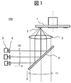
- FIG. 1 is a block diagram of the light source device in the first embodiment.
- the light source device 100 has an excitation light source 5, a mirror 4 and a phosphor wheel 1 as main components.
- the excitation light source 5 includes one or more solid light emitting elements such as a laser light emitting element, and emits B color laser light as excitation light.
- the excitation light 10 (shown by a solid line) emitted from the excitation light source 5 becomes substantially parallel light by the collimator lens 6 and enters the mirror 4.
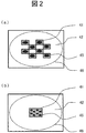
- FIG. 2 shows a specific example of the mirror 4 (here, two examples).
- the mirror 4 is composed of two areas.
- the first region is a dichroic coated region 41 (hatched portion) having a characteristic of reflecting the wavelength region of the excitation light (B) and transmitting the wavelength region (Y) of the fluorescent light.
- the second region is a wide wavelength transmission region 42 (white portion) transmitting both wavelength regions of excitation light and fluorescence light.
- the first region has a smaller area than the second region.
- the excitation light 10 is reflected by the dichroic coating region 41 of the mirror 4, condensed by the condensing lens 3, and is incident on the phosphor wheel 1. Then, substantially all of the fluorescence light emitted from the phosphor 2 on the phosphor wheel 1 and most of the diffused excitation light diffused as excitation light without being converted into fluorescence light become illumination light 11 as shown in FIG. 1) Emit downward.
- the dichroic coating area 41 is divided into a checkered pattern at the center of the incident surface of the mirror 4, and the other part is a wide wavelength transmission area 42.
- the number of divisions of the dichroic coating area 41 and the size and arrangement thereof are determined in accordance with the number, shape and position of the incident spots 45 (black) of the excitation light 10 from the excitation light source 5. Therefore, the excitation light 10 is reflected at the incident spot 45 and travels to the phosphor wheel 1 substantially all.
- the fluorescent light and the diffused excitation light generated by the fluorescent substance 2 on the fluorescent substance wheel 1 are expanded to be incident on the spot 46 (broken line) on the incident surface of the mirror 4. Among them, substantially all of the fluorescent light in the spot 46 passes through to become illumination light.
- the light incident on the dichroic coating region 41 can not be transmitted and becomes loss of illumination light, but most of the diffused excitation light incident on the large wavelength wide wavelength transmission region 42 is transmitted. It becomes illumination light.
- FIG. 2 (b) shows a form different from that of FIG. 2 (a).
- the difference from FIG. 2A is that a dichroic coating region 41 is provided in a rectangular (or square) shape at the center of the incident surface of the mirror 4.
- the incident spot 45 is small, all the spots 45 can be accommodated in one dichroic coated area 41.
- the area of the dichroic coating region 41 can be further reduced, the loss of the illumination light by the dichroic coating region 41 is further reduced.
- the loss of illumination light in the dichroic coat area 41 depends on the area of the dichroic coat area 41. According to the simulation, by reducing the area of the dichroic coating region 41 to, for example, 3% or less of the incident spot 46, it is possible to suppress the loss to the same as the case of Patent Document 1.
- the mirror 4 of the present embodiment selectively reflects the excitation light 10 from the excitation light source 5 by providing the dichroic coating region 41 in the wide wavelength transmission region 42, and the phosphor 4 on the phosphor wheel 1.
- the fluorescent light and the diffused excitation light from the phosphor 2 can be transmitted as illumination light 11 while being guided to the phosphor 2.
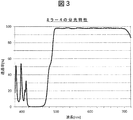
- FIG. 3 is a diagram showing an example of the spectral characteristics of the dichroic coating region 41 of the mirror 4.
- the horizontal axis represents the wavelength, and the vertical axis represents the transmittance.
- the dichroic coating region 41 does not transmit the wavelength band of B (about 420 to 470 nm), but transmits wavelength bands (R, Y, G) larger than that.
- Such spectral characteristics can be realized by using dielectric multilayer films (TiO 2 , SiO 2, etc.).
- FIG. 4 is a view showing a specific example of the phosphor wheel 1.
- the rotatable phosphor wheel 1 has a Y phosphor 2 that is excited by the excitation light to emit Y-color fluorescence light.
- the Y phosphor 2 receives the excitation light 10
- the Y phosphor 2 generates Y fluorescence light and diffuse excitation light which is diffused and reflected as it is without being converted into Y fluorescence light, and these Y fluorescence
- the light and the diffuse excitation light are mixed to form substantially white light, and the light is condensed into substantially parallel light by the condensing lens 3 and is incident on the mirror 4.
- the fluorescent light component of the white light incident on the mirror 4 is transmitted through both the dichroic coating region 41 and the wide wavelength transmission region 42.
- the diffused excitation light component incident on the mirror 4 is reflected by the dichroic coating region 41 but is transmitted by the wide wavelength transmission region 42.
- substantially all of the fluorescent light and most of the diffused excitation light become white illumination light 11 and are emitted downward in the drawing (FIG. 1).
- the phosphor In order to give the phosphor a diffusion function of excitation light, it is preferable to perform machining processing or chemical surface treatment for providing fine asperities on the phosphor surface 2a. Alternatively, a thin highly heat-resistant transmission diffusion plate may be attached to the phosphor surface 2a. Furthermore, in the case where the Y phosphor 2 to be applied is thin, it is preferable to apply mechanical processing or chemical surface treatment to provide fine asperities on the reflecting surface of the phosphor wheel 1 base before applying the Y phosphor 2. . As such, by diffusing the reflected excitation light, there is an effect of removing speckle noise in the laser light. Further, as the phosphor wheel 1 rotates, the effect of removing speckle noise is further enhanced.
- FIG. 5 is a view showing the degree of diffusion of the light emitted from the phosphor wheel 1.
- fluorescent light from the Y phosphor 2 of the phosphor wheel 1 emits light substantially uniformly in all directions, and is reflected by the mirror surface formed on the back surface of the phosphor, resulting in a hemispherical shape on the condenser lens 3 side. Emit at. Among them, the portion incident on the effective range of the condenser lens 3 reaches the mirror 4 and is used as the illumination light 11.
- the diffused excitation light diffused as excitation light without being converted into fluorescent light by the Y phosphor 2 is emitted hemispherically to the condensing lens 3 side, but the diffusion degree (diffusion angle ⁇ ) It can be adjusted by the processing etc. and the material of the diffusion plate. At that time, if the diffusion angle ⁇ of the diffused excitation light to be emitted is made too large, the light leaks out to the outside of the effective range of the condensing lens 3 and the light utilization efficiency is lowered. Conversely, if the diffusion angle ⁇ is too small, only the central portion of the effective range of the condenser lens 3 will pass.
- the ratio of the diffused excitation light incident on the dichroic coating region 41 of the mirror 4 becomes relatively large, and the loss as illumination light increases. Therefore, it is preferable to adjust the diffusion angle ⁇ so that the diffused excitation light from the Y phosphor 2 diffuses and enters approximately the size of the effective area of the condensing lens 3.
- both the fluorescent light generated by the phosphor 2 and the diffused excitation light are emitted from the phosphor wheel 1 to the same side, and most of the light passes through the mirror 4 to become white illumination light. Therefore, there is no need to provide an extra optical system for combining the two, and the apparatus can be miniaturized.
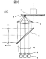
- FIG. 6 is a block diagram of the light source device in the second embodiment.
- the basic configuration of the light source device 100 ′ is the same as that of the first embodiment (FIG. 1), but the excitation light source 5 is disposed at the lower side in the drawing and the illumination light is used. It differs in that it emits in the left of the drawing. That is, although the mirror 4 'has the configuration shown in FIG.
- the dichroic coated region 41 has a characteristic of transmitting the wavelength range of the excitation light (B) and reflecting the wavelength range (R, Y, G) of the fluorescent light
- the wide wavelength reflection area 42 has a characteristic of reflecting the wavelength range of both the excitation light and the fluorescence light. Further, in the dichroic coating region 41, the vertical axis of the spectral characteristic shown in FIG. 3 is reversed, that is, the vertical axis is replaced with the transmittance from the reflectance.
- the excitation light 10 incident from the excitation light source 5 passes through the dichroic coating region 41 of the mirror 4 ′, is condensed by the condensing lens 3, and is incident on the phosphor wheel 1.
- fluorescent light of Y color and diffused excitation light of B color are generated from the phosphor 2 of the phosphor wheel 1.
- the fluorescent light and the diffusion excitation light become substantially parallel light by the condenser lens 3 and enter the mirror 4 '.
- the fluorescent light incident on the mirror 4 ' is reflected in any of the dichroic coated area 41 and the wide wavelength transmission area 42 in the mirror 4'.
- the diffused excitation light incident on the mirror 4 ′ is transmitted in the dichroic coating region 41 but is reflected in the wide wavelength reflection region 42.
- all of the fluorescent light and most of the diffused excitation light become illumination light 11 and are emitted leftward in the drawing (FIG. 6).
- both the fluorescent light and the diffused excitation light generated by the phosphor wheel 1 are emitted from the phosphor wheel 1 to the same side (the lower side in the drawing), and most of the light is reflected by the mirror 4 'to be illumination light. . Therefore, there is no need to provide an extra optical system for combining the two, and the apparatus can be miniaturized.
- the case where the phosphor wheel 1 of the light source device of the above embodiment is changed to a phosphor plate will be described.
- a fixed-type phosphor plate relative to the rotating phosphor wheel 1
- the heat generated when irradiating excitation light to the phosphor can not be cooled by the rotation operation, so a phosphor with high heat resistance is required .
- it is converted to a silicon-based organic binder used for holding and dispersing the phosphor with the conventional phosphor wheel 1, and an inorganic binder (binder for holding and dispersing the phosphor) Glass-based, ceramic-based) is used.
- the phosphor can be cooled by forming the substrate of the phosphor plate with a metal having high thermal conductivity.
- the area of the phosphor can be reduced, and further miniaturization of the device can be realized.
- the phosphor of the phosphor plate have a function of diffusing the excitation light, it is the same as the case of the phosphor wheel described in the first embodiment.
- optical axis adjustment in the first to third embodiments will be described.
- the light source device it is necessary to reflect or transmit the excitation light emitted from the excitation light source 5 at a specific area (dichroic coating area 41) of the mirror 4 and to condense it at a specific position (phosphor 2) of the phosphor wheel 1. There is. Therefore, a mechanism is provided to adjust the error with respect to the deviation between the emission position and the emission direction caused by the excitation light source 5.
- the excitation light source 5 and the collimator lens 6 have an integral structure
- the excitation light source 5 and the collimator lens 6 are integrally moved and adjusted in the direction perpendicular to the optical axis with respect to the deviation of the emission position and emission direction of the excitation light.
- the excitation light source 5 and the collimator lens 6 are separate structures, only the collimator lens 6 is moved in the direction perpendicular to the optical axis to adjust for the deviation of the emission position and the emission direction of the excitation light.
- the excitation light emitted from the excitation light source 5 can be reliably condensed on a specific position of the phosphor wheel 1 via the mirror 4, and the reduction of the illumination light intensity can be prevented.
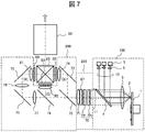
- FIG. 7 is a block diagram of an optical system of the projection type image display apparatus in the fourth embodiment, and shows an example using liquid crystal panels corresponding to three colors (R, G, B) as image display elements.
- the illumination light (fluorescent light and diffuse excitation light) 11 transmitted through the mirror 4 of the light source device 100 proceeds to the illumination optical system 200.
- the illumination optical system 200 includes an integrator optical system 70, a polarization conversion element 87, and a superimposing lens 71.
- the integrator optical system 70 includes a first fly's eye lens 70a and a second fly's eye lens 70b, each of which comprises a plurality of element lenses arranged in a matrix.
- the plurality of element lenses constituting the first fly's eye lens 70a divides the illumination light 11 and condenses it separately.
- the plurality of element lenses constituting the second fly's eye lens 70b emit the split light beams from the first fly's eye lens 70a at an appropriate divergence angle.
- the integrator optical system 70 makes the light intensity distribution of the illumination light 11 uniform.
- the polarization conversion element 87 is formed by an array having a PBS, a mirror, a retardation plate and the like as one set of elements, and the polarization direction of each partial beam split by the first fly eye lens 70a is linearly polarized in one direction. Align to.
- the superimposing lens 71 appropriately converges the illumination light having passed through the polarization conversion element 87 as a whole, and enables superimposing illumination to the illumination target area of the liquid crystal panels 82, 83, 84.
- the color separation optical system 300 separates the light from the illumination optical system 200 into R light, G light, and B light, and guides the light to the liquid crystal panels corresponding to them.
- the B light is reflected by the dichroic mirror 72 and enters the B light liquid crystal panel 82 via the reflection mirror 73 and the field lens 79.
- the G light and the R light are separated by the dichroic mirror 74 after being transmitted through the dichroic mirror 72.
- the G light is reflected by the dichroic mirror 74, transmitted through the field lens 80, and incident on the G light liquid crystal panel 83.
- the R light passes through the dichroic mirror 74 and enters the R light liquid crystal panel 84 via the relay lenses 77 and 78, the reflection mirrors 75 and 76, and the field lens 81.
- Each of the liquid crystal panels 82, 83, 84 modulates each color light incident thereon according to each video signal to form an optical image of each color light.
- the optical image of each color light is incident on the color combining prism 85.
- a dichroic film that reflects B light and a dichroic film that reflects R light are formed in a substantially X shape.
- the B light and R light incident from the liquid crystal panels 82 and 84 are respectively reflected by the dichroic film for B light and the dichroic film for R light.
- the G light incident from the liquid crystal panel 83 transmits each dichroic film.
- the combined light emitted from the color combining prism 85 enters the projection lens 86 and is projected on a screen (not shown).
- the example in which the light source device of the above embodiment is applied to a projection type image display device is not limited to the transmissive liquid crystal element, but may be a reflective liquid crystal element.
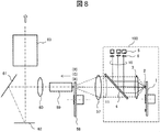
- the fifth embodiment is another example of the projection type video display apparatus, and is applied to a DMD (Digital Mirror Device) as a video display element.
- FIG. 8 is a block diagram of the optical system of the projection type video display in the fifth embodiment.
- the illumination light (fluorescent light and diffused excitation light) 11 transmitted through the mirror 4 of the light source device 100 is condensed by the condensing lens 57, passes through the color wheel 58, and is incident on the multiple reflection element 59.
- the color wheel 58 is configured such that color filters of three colors (R 1, G 2, and B) are arranged in a disk shape, and white light of the illumination light 11 emitted from the light source device 100 is transmitted through the respective color filters. It is separated into three-color light of a predetermined wavelength.
- the three-color light incident on the multiple reflection element 59 is reflected a plurality of times in the multiple reflection element 59, and becomes light having a uniform illuminance distribution.
- the three-color light emitted from the emission aperture surface of the multiple reflection element 59 is transmitted through the condenser lens 60, reflected by the reflection mirror 61, and then irradiated onto the image display element 62 with a uniform illuminance distribution.
- the color wheel 58 and the image display element 62 are synchronized, and the image display element 62 is irradiated with three-color light in a time division manner, whereby the light is modulated for each color light.
- Each color light reflected by the image display element 62 becomes image light, enters the projection lens 63, and is projected on a screen (not shown).
- the light source device 100 'of FIG. 5 may be used instead of the light source device 100, or the fluorescence wheel of the light source device 100/100' may be changed to a fluorescent plate. .
- the above-mentioned projection type video display device uses a compact light source device with a small illumination light loss and contributes to the miniaturization and high performance of the projection type video display device.
- Phosphor wheel 2 Fluorescent substance 3: Focusing lens 4: Mirror 5: Excitation light source 6: Collimation lens 10: Excitation light 11: Illumination light (fluorescent light and diffuse excitation light) 41 : Dichroic coat area (first area), 42: wide wavelength transmission area (second area), 100: light source device, 200: illumination optical system, 300: color separation optical system.
Landscapes
- Physics & Mathematics (AREA)
- General Physics & Mathematics (AREA)
- Engineering & Computer Science (AREA)
- Optics & Photonics (AREA)
- Multimedia (AREA)
- Signal Processing (AREA)
- Spectroscopy & Molecular Physics (AREA)
- Astronomy & Astrophysics (AREA)
- General Engineering & Computer Science (AREA)
- Projection Apparatus (AREA)
- Non-Portable Lighting Devices Or Systems Thereof (AREA)
- Video Image Reproduction Devices For Color Tv Systems (AREA)
Abstract
Description
Claims (10)
- 励起光として青色レーザー光を発生する励起光源と、
前記励起光源からの励起光に励起されて黄色の蛍光光を発生する蛍光体を有する蛍光体ホイールと、
前記励起光源からの励起光を前記蛍光体ホイールに導き、前記蛍光体ホイールからの蛍光光を透過するミラーとを備え、前記ミラーは、
前記励起光を反射し前記蛍光光を透過する第1の領域と、前記蛍光光及び前記蛍光体にて拡散反射した拡散励起光を透過する第2の領域を有する、光源装置。 - 前記ミラーを透過した前記黄色の蛍光光と前記拡散励起光は混色し、白色光を発生する、請求項1記載の光源装置。
- 励起光として青色レーザー光を発生する励起光源と、
前記励起光源からの励起光に励起されて黄色の蛍光光を発生する蛍光体を有する蛍光体ホイールと、
前記励起光源からの励起光を前記蛍光体ホイールに導き、前記蛍光体ホイールからの蛍光光を反射するミラーとを備え、前記ミラーは、
前記励起光を透過し前記蛍光光を反射する第1の領域と、前記蛍光光及び前記蛍光体にて拡散反射した拡散励起光を反射する第2の領域を有する、光源装置。 - 前記ミラーを反射した前記黄色の蛍光光と前記拡散励起光は混色し、白色光を発生する、請求項3記載の光源装置。
- 励起光として青色レーザー光を発生する励起光源と、
前記励起光源からの励起光に励起されて黄色の蛍光光を発生する蛍光体を有する蛍光体プレ-トと、
前記励起光源からの励起光を前記蛍光体プレ-トに導き、前記蛍光体プレ-トからの蛍光光を透過するミラーとを備え、前記ミラーは、
前記励起光を反射し前記蛍光光を透過する第1の領域と、前記蛍光光及び前記蛍光体にて拡散反射した拡散励起光を透過する第2の領域を有する、光源装置。 - 前記ミラーを透過した前記黄色の蛍光光と前記拡散励起光は混色し、白色光を発生する、請求項5記載の光源装置。
- 励起光として青色レーザー光を発生する励起光源と、
前記励起光源からの励起光に励起されて黄色の蛍光光を発生する蛍光体を有する蛍光体プレ-トと、
前記励起光源からの励起光を前記蛍光体プレ-トに導き、前記蛍光体プレ-トからの蛍光光を反射するミラーとを備え、前記ミラーは、
前記励起光を透過し前記蛍光光を反射する第1の領域と、前記蛍光光及び前記蛍光体にて拡散反射した拡散励起光を反射する第2の領域を有する、光源装置。 - 前記ミラーを反射した前記黄色の蛍光光と前記拡散励起光は混色し、白色光を発生する、請求項7記載の光源装置。
- 前記励起光源は複数の光源からなり、
前記第1の領域は、前記複数の光源からの各励起光が入射する各位置に対応し、複数の領域に分割して設けられる、請求項1乃至8何れか一に記載の光源装置。 - 請求項1乃至9何れか一に記載の光源装置と、
入力信号に応じて各色光を変調する映像表示素子と、
前記映像表示素子により変調された光を投写する投写手段と、を備える、投写型映像表示装置。
Priority Applications (4)
| Application Number | Priority Date | Filing Date | Title |
|---|---|---|---|
| JP2015513367A JP6085025B2 (ja) | 2013-04-22 | 2013-04-22 | 光源装置及び投写型映像表示装置 |
| PCT/JP2013/061714 WO2014174560A1 (ja) | 2013-04-22 | 2013-04-22 | 光源装置及び投写型映像表示装置 |
| US14/786,515 US9648291B2 (en) | 2013-04-22 | 2013-04-22 | Light source device and projection type image display device |
| CN201380075865.8A CN105190432B (zh) | 2013-04-22 | 2013-04-22 | 光源装置和投影型影像显示装置 |
Applications Claiming Priority (1)
| Application Number | Priority Date | Filing Date | Title |
|---|---|---|---|
| PCT/JP2013/061714 WO2014174560A1 (ja) | 2013-04-22 | 2013-04-22 | 光源装置及び投写型映像表示装置 |
Publications (1)
| Publication Number | Publication Date |
|---|---|
| WO2014174560A1 true WO2014174560A1 (ja) | 2014-10-30 |
Family
ID=51791171
Family Applications (1)
| Application Number | Title | Priority Date | Filing Date |
|---|---|---|---|
| PCT/JP2013/061714 Ceased WO2014174560A1 (ja) | 2013-04-22 | 2013-04-22 | 光源装置及び投写型映像表示装置 |
Country Status (4)
| Country | Link |
|---|---|
| US (1) | US9648291B2 (ja) |
| JP (1) | JP6085025B2 (ja) |
| CN (1) | CN105190432B (ja) |
| WO (1) | WO2014174560A1 (ja) |
Cited By (16)
| Publication number | Priority date | Publication date | Assignee | Title |
|---|---|---|---|---|
| CN104635411A (zh) * | 2015-01-27 | 2015-05-20 | 上海理工大学 | 投影显示系统 |
| WO2016072360A1 (ja) * | 2014-11-05 | 2016-05-12 | ウシオ電機株式会社 | 多波長光源および光源装置 |
| JP2016095486A (ja) * | 2014-11-05 | 2016-05-26 | ウシオ電機株式会社 | 多波長光源および光源装置 |
| WO2016121855A1 (ja) * | 2015-01-30 | 2016-08-04 | コニカミノルタ株式会社 | 投射型表示装置用カラーホイール及びその製造方法、並びにこれを含む投射型表示装置 |
| JP2017032762A (ja) * | 2015-07-31 | 2017-02-09 | キヤノン株式会社 | 光源光学系及びこれを用いた光源装置、投射型表示装置 |
| JP2017125947A (ja) * | 2016-01-14 | 2017-07-20 | 株式会社Jvcケンウッド | 投射型画像表示装置 |
| JP2017156403A (ja) * | 2016-02-29 | 2017-09-07 | ウシオ電機株式会社 | 蛍光光源装置 |
| JP2017167528A (ja) * | 2016-03-15 | 2017-09-21 | パナソニックIpマネジメント株式会社 | 光源装置及び投写型映像表示装置 |
| JP2017167309A (ja) * | 2016-03-16 | 2017-09-21 | キヤノン株式会社 | 光学素子、光源装置および画像投射装置 |
| JP2017194523A (ja) * | 2016-04-19 | 2017-10-26 | キヤノン株式会社 | 光源装置および画像投射装置 |
| JP2018036547A (ja) * | 2016-09-01 | 2018-03-08 | 株式会社Jvcケンウッド | 発光装置及び投射型画像表示装置 |
| JP2018084757A (ja) * | 2016-11-25 | 2018-05-31 | セイコーエプソン株式会社 | 照明装置及びプロジェクター |
| JP2018138941A (ja) * | 2017-02-24 | 2018-09-06 | セイコーエプソン株式会社 | 照明装置及びプロジェクター |
| US10317045B2 (en) | 2015-03-05 | 2019-06-11 | Signify Holding B.V. | Light emitting apparatus for emitting light of variable spectral composition using movable element |
| CN110955103A (zh) * | 2018-09-26 | 2020-04-03 | 中强光电股份有限公司 | 投影装置及其光源模块与波长转换轮及滤光轮同步方法 |
| US12578078B2 (en) * | 2021-04-01 | 2026-03-17 | Signify Holding B.V. | Phosphor converted superluminescent diode light source |
Families Citing this family (20)
| Publication number | Priority date | Publication date | Assignee | Title |
|---|---|---|---|---|
| JP6085025B2 (ja) * | 2013-04-22 | 2017-02-22 | 日立マクセル株式会社 | 光源装置及び投写型映像表示装置 |
| KR20150123064A (ko) * | 2014-04-24 | 2015-11-03 | 삼성전자주식회사 | 조명장치 및 이를 구비한 투사형 영상표시장치 |
| CN105467737A (zh) * | 2015-12-29 | 2016-04-06 | 海信集团有限公司 | 一种激光光源装置和激光投影设备 |
| CN105607400A (zh) * | 2015-12-29 | 2016-05-25 | 海信集团有限公司 | 一种激光光源装置和激光投影设备 |
| JP2018031995A (ja) * | 2016-08-26 | 2018-03-01 | 株式会社ライトショー・テクノロジー | 光源装置および投射型表示装置 |
| CN106406004B (zh) * | 2016-12-12 | 2018-02-09 | 广景视睿科技(深圳)有限公司 | 一种曲面波长转换系统 |
| JP6946651B2 (ja) * | 2017-02-01 | 2021-10-06 | セイコーエプソン株式会社 | 光源装置及びプロジェクター |
| JP6911391B2 (ja) * | 2017-03-06 | 2021-07-28 | セイコーエプソン株式会社 | 照明装置及びプロジェクター |
| CN106949439A (zh) * | 2017-03-22 | 2017-07-14 | 中国科学院苏州生物医学工程技术研究所 | 一种基于荧光激发的光源装置 |
| CN106979460A (zh) * | 2017-03-29 | 2017-07-25 | 中国科学院苏州生物医学工程技术研究所 | 一种荧光光源及荧光显微成像系统 |
| KR102488528B1 (ko) * | 2017-09-20 | 2023-01-17 | 마테리온 프레시젼 옵틱스 (상하이) 리미티드 | 무기질 바인더를 갖는 인광체 휠 |
| JP6511546B1 (ja) * | 2018-01-10 | 2019-05-15 | 株式会社ライトショー・テクノロジー | 光源装置および投射型表示装置 |
| JP2019133080A (ja) * | 2018-02-02 | 2019-08-08 | マクセル株式会社 | プロジェクタ |
| JP2020052236A (ja) * | 2018-09-27 | 2020-04-02 | キヤノン株式会社 | 光源装置およびそれを用いた画像投射装置 |
| WO2021009790A1 (ja) * | 2019-07-12 | 2021-01-21 | シャープNecディスプレイソリューションズ株式会社 | 光源装置、プロジェクター及び光強度分布均一化方法 |
| CN112213908B (zh) * | 2019-07-12 | 2022-12-02 | 深圳光峰科技股份有限公司 | 光源系统与显示设备 |
| JP2021124605A (ja) * | 2020-02-05 | 2021-08-30 | ソニーグループ株式会社 | 光学システム |
| WO2021259270A1 (zh) | 2020-06-22 | 2021-12-30 | 青岛海信激光显示股份有限公司 | 光源组件和投影设备 |
| US12429756B2 (en) | 2020-06-22 | 2025-09-30 | Hisense Laser Display Co., Ltd | Laser projection apparatus |
| JP2022146401A (ja) | 2021-03-22 | 2022-10-05 | セイコーエプソン株式会社 | 光源装置およびプロジェクター |
Citations (7)
| Publication number | Priority date | Publication date | Assignee | Title |
|---|---|---|---|---|
| JP2005316406A (ja) * | 2004-03-30 | 2005-11-10 | Sanyo Electric Co Ltd | 光学部材及び照明装置及び投写型映像表示装置 |
| JP2012004009A (ja) * | 2010-06-18 | 2012-01-05 | Sony Corp | 照明装置及び画像表示装置 |
| JP2012015001A (ja) * | 2010-07-02 | 2012-01-19 | Stanley Electric Co Ltd | 光源装置、色調整方法、照明装置 |
| JP2012027106A (ja) * | 2010-07-21 | 2012-02-09 | Hitachi Consumer Electronics Co Ltd | 投写型映像表示装置 |
| JP2012128297A (ja) * | 2010-12-17 | 2012-07-05 | Hitachi Consumer Electronics Co Ltd | 光源装置 |
| JP2012141495A (ja) * | 2011-01-05 | 2012-07-26 | Seiko Epson Corp | 光源装置及びプロジェクター |
| JP2012212129A (ja) * | 2011-03-23 | 2012-11-01 | Panasonic Corp | 光源装置及びそれを用いた画像表示装置 |
Family Cites Families (11)
| Publication number | Priority date | Publication date | Assignee | Title |
|---|---|---|---|---|
| JP4711154B2 (ja) | 2009-06-30 | 2011-06-29 | カシオ計算機株式会社 | 光源装置及びプロジェクタ |
| DE102010001942B4 (de) * | 2010-02-15 | 2012-03-29 | Osram Ag | Lichtquelleneinheit und Projektor mit einer derartigen Lichtquelleneinheit |
| JP5483505B2 (ja) * | 2010-05-21 | 2014-05-07 | Necディスプレイソリューションズ株式会社 | 照明光学系とこれを用いたプロジェクタ |
| JP2012014972A (ja) * | 2010-07-01 | 2012-01-19 | Seiko Epson Corp | 光源装置及びプロジェクター |
| EP2466375B1 (en) * | 2010-12-17 | 2019-12-25 | Maxell, Ltd. | Light Source Apparatus |
| JP5223941B2 (ja) * | 2011-03-28 | 2013-06-26 | カシオ計算機株式会社 | 投影装置 |
| CN102563410B (zh) | 2011-12-04 | 2014-08-06 | 深圳市光峰光电技术有限公司 | 发光装置、投影装置和照明装置 |
| CN104020633B (zh) * | 2013-02-28 | 2015-12-09 | 深圳市绎立锐光科技开发有限公司 | 发光装置及相关投影系统 |
| JP5997077B2 (ja) * | 2013-03-07 | 2016-09-21 | 日立マクセル株式会社 | 光源装置 |
| CN104111532B (zh) * | 2013-04-20 | 2017-08-29 | 深圳市绎立锐光科技开发有限公司 | 发光装置及相关光源系统 |
| JP6085025B2 (ja) * | 2013-04-22 | 2017-02-22 | 日立マクセル株式会社 | 光源装置及び投写型映像表示装置 |
-
2013
- 2013-04-22 JP JP2015513367A patent/JP6085025B2/ja active Active
- 2013-04-22 WO PCT/JP2013/061714 patent/WO2014174560A1/ja not_active Ceased
- 2013-04-22 CN CN201380075865.8A patent/CN105190432B/zh active Active
- 2013-04-22 US US14/786,515 patent/US9648291B2/en active Active
Patent Citations (7)
| Publication number | Priority date | Publication date | Assignee | Title |
|---|---|---|---|---|
| JP2005316406A (ja) * | 2004-03-30 | 2005-11-10 | Sanyo Electric Co Ltd | 光学部材及び照明装置及び投写型映像表示装置 |
| JP2012004009A (ja) * | 2010-06-18 | 2012-01-05 | Sony Corp | 照明装置及び画像表示装置 |
| JP2012015001A (ja) * | 2010-07-02 | 2012-01-19 | Stanley Electric Co Ltd | 光源装置、色調整方法、照明装置 |
| JP2012027106A (ja) * | 2010-07-21 | 2012-02-09 | Hitachi Consumer Electronics Co Ltd | 投写型映像表示装置 |
| JP2012128297A (ja) * | 2010-12-17 | 2012-07-05 | Hitachi Consumer Electronics Co Ltd | 光源装置 |
| JP2012141495A (ja) * | 2011-01-05 | 2012-07-26 | Seiko Epson Corp | 光源装置及びプロジェクター |
| JP2012212129A (ja) * | 2011-03-23 | 2012-11-01 | Panasonic Corp | 光源装置及びそれを用いた画像表示装置 |
Cited By (18)
| Publication number | Priority date | Publication date | Assignee | Title |
|---|---|---|---|---|
| WO2016072360A1 (ja) * | 2014-11-05 | 2016-05-12 | ウシオ電機株式会社 | 多波長光源および光源装置 |
| JP2016095486A (ja) * | 2014-11-05 | 2016-05-26 | ウシオ電機株式会社 | 多波長光源および光源装置 |
| CN104635411A (zh) * | 2015-01-27 | 2015-05-20 | 上海理工大学 | 投影显示系统 |
| WO2016121855A1 (ja) * | 2015-01-30 | 2016-08-04 | コニカミノルタ株式会社 | 投射型表示装置用カラーホイール及びその製造方法、並びにこれを含む投射型表示装置 |
| US10317045B2 (en) | 2015-03-05 | 2019-06-11 | Signify Holding B.V. | Light emitting apparatus for emitting light of variable spectral composition using movable element |
| JP2017032762A (ja) * | 2015-07-31 | 2017-02-09 | キヤノン株式会社 | 光源光学系及びこれを用いた光源装置、投射型表示装置 |
| US9835937B2 (en) | 2016-01-14 | 2017-12-05 | JVC Kenwood Corporation | Projection-type image display device |
| JP2017125947A (ja) * | 2016-01-14 | 2017-07-20 | 株式会社Jvcケンウッド | 投射型画像表示装置 |
| EP3203732A1 (en) * | 2016-01-14 | 2017-08-09 | JVC KENWOOD Corporation | Projection-type image display device |
| JP2017156403A (ja) * | 2016-02-29 | 2017-09-07 | ウシオ電機株式会社 | 蛍光光源装置 |
| JP2017167528A (ja) * | 2016-03-15 | 2017-09-21 | パナソニックIpマネジメント株式会社 | 光源装置及び投写型映像表示装置 |
| JP2017167309A (ja) * | 2016-03-16 | 2017-09-21 | キヤノン株式会社 | 光学素子、光源装置および画像投射装置 |
| JP2017194523A (ja) * | 2016-04-19 | 2017-10-26 | キヤノン株式会社 | 光源装置および画像投射装置 |
| JP2018036547A (ja) * | 2016-09-01 | 2018-03-08 | 株式会社Jvcケンウッド | 発光装置及び投射型画像表示装置 |
| JP2018084757A (ja) * | 2016-11-25 | 2018-05-31 | セイコーエプソン株式会社 | 照明装置及びプロジェクター |
| JP2018138941A (ja) * | 2017-02-24 | 2018-09-06 | セイコーエプソン株式会社 | 照明装置及びプロジェクター |
| CN110955103A (zh) * | 2018-09-26 | 2020-04-03 | 中强光电股份有限公司 | 投影装置及其光源模块与波长转换轮及滤光轮同步方法 |
| US12578078B2 (en) * | 2021-04-01 | 2026-03-17 | Signify Holding B.V. | Phosphor converted superluminescent diode light source |
Also Published As
| Publication number | Publication date |
|---|---|
| US20160088273A1 (en) | 2016-03-24 |
| US9648291B2 (en) | 2017-05-09 |
| JP6085025B2 (ja) | 2017-02-22 |
| CN105190432A (zh) | 2015-12-23 |
| JPWO2014174560A1 (ja) | 2017-02-23 |
| CN105190432B (zh) | 2017-07-28 |
Similar Documents
| Publication | Publication Date | Title |
|---|---|---|
| JP6085025B2 (ja) | 光源装置及び投写型映像表示装置 | |
| JP5997077B2 (ja) | 光源装置 | |
| US11726396B2 (en) | Light source device and projection-type display apparatus | |
| JP5743240B2 (ja) | 蛍光体を備えた照明光学系、プロジェクタ、および照射方法 | |
| US11215910B2 (en) | Light source device and projection display apparatus having a laser optical system, a fluorescence optical system, and a light combiner | |
| JP6039053B2 (ja) | 光源装置 | |
| JP5675320B2 (ja) | 光源装置、および、投写型映像表示装置 | |
| JP2017204357A (ja) | 光源装置及びプロジェクター | |
| CN107065410A (zh) | 投影型图像显示装置 | |
| US20200319541A1 (en) | Light source device and projection display apparatus | |
| US9891514B2 (en) | Light source apparatus and projection display apparatus | |
| WO2015111145A1 (ja) | 光源装置およびこれを用いた映像表示装置 | |
| WO2014174559A1 (ja) | 光源装置及び映像表示装置 | |
| WO2016021002A1 (ja) | 光源装置、プロジェクタおよび光源装置の制御方法 | |
| JP2020024318A (ja) | 光源装置およびプロジェクター | |
| JP7330787B2 (ja) | 光源装置およびこれを備える画像投射装置 | |
| JP7257599B2 (ja) | 光源装置及び投写型映像表示装置 | |
| JP5433561B2 (ja) | 光源装置 | |
| JP7507339B2 (ja) | 光源装置および投写型表示装置 | |
| JP2023024245A (ja) | 波長変換プレート、光源装置および画像投射装置 | |
| CN115280234A (zh) | 光源设备和投影仪 | |
| JP2021005060A (ja) | 光源装置およびこれを備える画像投射装置 | |
| US20220026789A1 (en) | Illumination device and projector | |
| JP2016194699A (ja) | 蛍光体を備えた照明光学系およびプロジェクタ | |
| JP2021086009A (ja) | 光源装置およびプロジェクター |
Legal Events
| Date | Code | Title | Description |
|---|---|---|---|
| WWE | Wipo information: entry into national phase |
Ref document number: 201380075865.8 Country of ref document: CN |
|
| 121 | Ep: the epo has been informed by wipo that ep was designated in this application |
Ref document number: 13883268 Country of ref document: EP Kind code of ref document: A1 |
|
| ENP | Entry into the national phase |
Ref document number: 2015513367 Country of ref document: JP Kind code of ref document: A |
|
| NENP | Non-entry into the national phase |
Ref country code: DE |
|
| WWE | Wipo information: entry into national phase |
Ref document number: 14786515 Country of ref document: US |
|
| 122 | Ep: pct application non-entry in european phase |
Ref document number: 13883268 Country of ref document: EP Kind code of ref document: A1 |