WO2014171251A1 - 撮像装置及び像ブレ補正方法 - Google Patents
撮像装置及び像ブレ補正方法 Download PDFInfo
- Publication number
- WO2014171251A1 WO2014171251A1 PCT/JP2014/057392 JP2014057392W WO2014171251A1 WO 2014171251 A1 WO2014171251 A1 WO 2014171251A1 JP 2014057392 W JP2014057392 W JP 2014057392W WO 2014171251 A1 WO2014171251 A1 WO 2014171251A1
- Authority
- WO
- WIPO (PCT)
- Prior art keywords
- angular velocity
- panning
- unit
- tilting
- angular
- Prior art date
- Legal status (The legal status is an assumption and is not a legal conclusion. Google has not performed a legal analysis and makes no representation as to the accuracy of the status listed.)
- Ceased
Links
Images


Classifications
-
- G—PHYSICS
- G03—PHOTOGRAPHY; CINEMATOGRAPHY; ANALOGOUS TECHNIQUES USING WAVES OTHER THAN OPTICAL WAVES; ELECTROGRAPHY; HOLOGRAPHY
- G03B—APPARATUS OR ARRANGEMENTS FOR TAKING PHOTOGRAPHS OR FOR PROJECTING OR VIEWING THEM; APPARATUS OR ARRANGEMENTS EMPLOYING ANALOGOUS TECHNIQUES USING WAVES OTHER THAN OPTICAL WAVES; ACCESSORIES THEREFOR
- G03B5/00—Adjustment of optical system relative to image or object surface other than for focusing
-
- H—ELECTRICITY
- H04—ELECTRIC COMMUNICATION TECHNIQUE
- H04N—PICTORIAL COMMUNICATION, e.g. TELEVISION
- H04N23/00—Cameras or camera modules comprising electronic image sensors; Control thereof
- H04N23/60—Control of cameras or camera modules
- H04N23/68—Control of cameras or camera modules for stable pick-up of the scene, e.g. compensating for camera body vibrations
- H04N23/681—Motion detection
- H04N23/6815—Motion detection by distinguishing pan or tilt from motion
-
- H—ELECTRICITY
- H04—ELECTRIC COMMUNICATION TECHNIQUE
- H04N—PICTORIAL COMMUNICATION, e.g. TELEVISION
- H04N23/00—Cameras or camera modules comprising electronic image sensors; Control thereof
- H04N23/60—Control of cameras or camera modules
- H04N23/68—Control of cameras or camera modules for stable pick-up of the scene, e.g. compensating for camera body vibrations
- H04N23/682—Vibration or motion blur correction
- H04N23/685—Vibration or motion blur correction performed by mechanical compensation
- H04N23/687—Vibration or motion blur correction performed by mechanical compensation by shifting the lens or sensor position
-
- G—PHYSICS
- G03—PHOTOGRAPHY; CINEMATOGRAPHY; ANALOGOUS TECHNIQUES USING WAVES OTHER THAN OPTICAL WAVES; ELECTROGRAPHY; HOLOGRAPHY
- G03B—APPARATUS OR ARRANGEMENTS FOR TAKING PHOTOGRAPHS OR FOR PROJECTING OR VIEWING THEM; APPARATUS OR ARRANGEMENTS EMPLOYING ANALOGOUS TECHNIQUES USING WAVES OTHER THAN OPTICAL WAVES; ACCESSORIES THEREFOR
- G03B2217/00—Details of cameras or camera bodies; Accessories therefor
- G03B2217/005—Blur detection
-
- H—ELECTRICITY
- H04—ELECTRIC COMMUNICATION TECHNIQUE
- H04N—PICTORIAL COMMUNICATION, e.g. TELEVISION
- H04N23/00—Cameras or camera modules comprising electronic image sensors; Control thereof
- H04N23/60—Control of cameras or camera modules
- H04N23/68—Control of cameras or camera modules for stable pick-up of the scene, e.g. compensating for camera body vibrations
- H04N23/681—Motion detection
- H04N23/6812—Motion detection based on additional sensors, e.g. acceleration sensors
Definitions
- the present invention relates to an imaging apparatus and an image blur correction method for correcting image quality deterioration due to image blur caused by camera shake.
- imaging devices such as cameras equipped with a camera shake correction function have become widespread. With such a camera, it has become possible to shoot a good photographic image that does not cause image blur due to camera shake without special attention to camera shake during hand-held shooting.
- a shooting technique called panning.
- the camera is shaken according to a moving subject, for example, while performing a panning operation in the horizontal direction and a tilting operation in the vertical direction.
- a moving subject is photographed without blurring, that is, the subject is photographed as if it has stopped, and the background of the moving subject flows in the direction of movement of the subject and blurs (image blurring), thereby making the subject stand out. You can shoot and express the movement of the subject.
- Patent Document 1 is a technique for dealing with such a problem.
- This Patent Document 1 drives a correction optical system based on a shake detection unit that detects a shake and outputs a shake detection signal, a correction optical system that corrects the shake, and a shake detection signal from the shake detection unit.
- a blur driving unit, and a panning determination unit that determines whether the shot is a panning based on the characteristics of the detection signal from which a high-frequency component of the blur detection signal from the blur detection unit is removed.
- a switching means is provided to block the shake detection signal when it is determined that the camera is shooting, and if it is determined that the panning is being performed, the camera shake correction of the camera shaker is automatically stopped and the panning operation is erroneously corrected. Disclose not to do so.
- the speed of shaking the camera (angular velocity) is not constant during panning.
- Image blur (shake) occurs in a direction perpendicular to the direction in which the camera is shaken.
- the speed of shaking the camera does not match the moving speed of the subject. It is difficult to correct a new image blur caused by. For this reason, in panning, an advanced operation of shaking the camera so as not to shake in accordance with a moving subject is required.
- the purpose of the present invention is that the speed at which the camera is shaken at the time of panning is not constant, even if the camera shakes in a direction orthogonal to the direction in which the camera is shaken, or the speed at which the camera is shaken does not match the moving speed of the subject.
- Another object of the present invention is to provide an image pickup apparatus and an image blur correction method that can correct image quality degradation due to image blur caused by camera shake.
- An imaging apparatus includes an optical system that forms an image of a subject, An image sensor that outputs an image signal of a subject image formed by the optical system; A first angular velocity detection unit that detects a first angular velocity when rotating in a first rotation direction with a vertical direction as a first axis with respect to the imaging plane of the imaging element; A second angular velocity detector that detects a second angular velocity when rotating in the second rotation direction with the second axis as the second axis on the imaging surface of the imaging element; A sink that detects whether or not a panning state is in effect based on the first angular velocity detected by the first angular velocity detector and the second angular velocity detected by the second angular velocity detector.
- a shooting detector An angular velocity calculation unit that calculates a panning angular velocity and a tilting angular velocity generated by the panning and corrects and calculates the first angular velocity and the second angular velocity when the panning detection unit detects the panning state.
- a panning control unit including A blur correction unit that calculates an image blur correction amount according to the first angular velocity and the second angular velocity corrected by the panning control unit; Based on the image blur correction amount calculated by the blur correction unit, one or both of the optical system and the image sensor are driven in a direction to cancel the image blur, and image blur generated on the imaging surface of the image sensor is detected.
- a blur driving unit to be corrected Comprising
- the panning control unit detects that the panning or tilting operation is in the panning state by the panning detection unit
- the angular velocity calculation unit calculates the first angular velocity and the second angular velocity.
- the rotation direction and the tilt angle which are the main directions of the panning shot, are determined based on the magnitude relationship between the absolute values of the first and second angles, and the first angular velocity based on one of the first and second angular velocities is determined based on the determination.
- the panning angular velocity and the tilting angular velocity which are reference angular velocities in the second direction, are respectively calculated based on the tilt angle immediately before exposure and a ratio between the first angular velocity and the second angular velocity.
- the blur correction unit calculates the image blur correction amount based on a difference between the first angular velocity and the panning angular velocity and a difference between the second angular velocity and the tilting angular velocity.
- An image blur correction method for an image pickup apparatus is an image pickup apparatus including an optical system that forms an image of an object and an image sensor that outputs an image signal from the image of the object formed by the optical system.
- An image blur correction method Detecting a first angular velocity when rotating in a first rotation direction with a vertical direction as a first axis with respect to an imaging plane of the image sensor; Detecting a second angular velocity when rotating in a second rotation direction with a direction orthogonal to the first axis on the imaging plane of the image sensor as a second axis; Based on the detected first angular velocity and the detected second angular velocity, it is detected whether the state is a panning shot, When it is detected that the panning state is detected, a panning angular velocity and a tilting angular velocity generated by the panning are calculated, and the first angular velocity and the second angular velocity are corrected and calculated.
- An image blur correction amount is calculated according to the first angular velocity and the second angular velocity that have been subjected to the correction calculation, Based on the calculated image blur correction amount, correct one or both of the optical system and the image sensor in a direction to cancel image blur and correct image blur generated on the imaging surface of the image sensor,
- the panning control when the panning or tilting operation is detected as the panning state, the panning is performed based on the magnitude relationship between the absolute values of the first angular velocity and the second angular velocity.
- the panning angular velocity and the tilting angular velocity that are reference angular velocities in the first or second direction based on either the first or the second angular velocity are set to the inclination angle immediately before the exposure.
- the image blur correction the image blur correction amount is calculated based on a difference between the first angular velocity and the panning angular velocity and a difference between the second angular velocity and the tilting angular velocity.
- the speed at which the camera is shaken at the time of panning is not constant, even if the camera shakes in a direction orthogonal to the direction in which the camera is shaken, or the speed at which the camera is shaken does not match the moving speed of the subject. It is possible to provide an imaging apparatus and an image blur correction method that can correct image quality degradation due to image blur caused by camera shake.
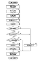
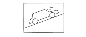
- FIG. 1 is an external configuration diagram showing a first embodiment of an imaging apparatus equipped with a panning detection function according to the present invention.
- FIG. 2 is a diagram showing a flow of panning operation in the apparatus.
- FIG. 3 is a diagram illustrating an example of a result of integrating the angular velocities ⁇ in the yaw direction and the pitch direction of the apparatus.
- FIG. 4 is a diagram for explaining a method of detecting the tilt of the camera body in the apparatus.
- FIG. 5 is a block diagram showing the overall configuration of the apparatus.
- FIG. 6 is a block diagram showing an internal configuration of a shake correction microcomputer in the apparatus.
- FIG. 7 is a specific block diagram showing a panning control unit in the apparatus.
- FIG. 8 is a specific block diagram showing a panning detection unit in the apparatus.
- FIG. 9 is a specific block diagram showing an offset detection unit in the apparatus.
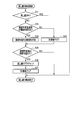
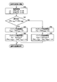
- FIG. 10 is a flowchart for starting the panning control of the apparatus.
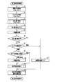
- FIG. 11 is a flow chart of the panning detection processing control in the apparatus.
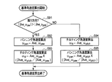
- FIG. 12 is a flowchart of starting calculation of the reference angular velocity in the apparatus.
- FIG. 13A is a live view image displayed on the EVF when the camera is shaken and chased with respect to a parallel moving object in the second embodiment of the imaging apparatus equipped with the panning detection function according to the present invention. It is a schematic diagram which shows the frame image.
- FIG. 13A is a live view image displayed on the EVF when the camera is shaken and chased with respect to a parallel moving object in the second embodiment of the imaging apparatus equipped with the panning detection function according to the present invention. It is a schematic diagram which shows the frame image.
- FIG. 13A is a live view image displayed
- FIG. 13B is a schematic diagram illustrating a frame image of a live view video displayed on the EVF in the same device.
- FIG. 13C is a diagram showing movement of a subject between frames in the apparatus.
- FIG. 13D is a diagram illustrating a state viewed from the back when the subject moving in parallel is imaged in the apparatus.
- FIG. 13E is a diagram showing a state in which the moving direction of the subject is converted into the horizontal direction when the apparatus is panned with the inclination in the angular velocity detection direction.
- FIG. 14 is a specific block diagram showing a panning control unit in the apparatus.
- FIG. 15 is a flowchart of starting calculation of the reference angular velocity in the apparatus.
- FIG. 16 is a flowchart for starting panning control in the apparatus.
- FIG. 1 is an external configuration diagram of an imaging apparatus such as a camera equipped with a panning detection function.
- an optical system 2 is provided on the front surface of the camera body 1 and a release switch (SW) 9 is provided on the upper surface.
- the movement that occurs in the camera body 1 is defined with reference to FIG.
- the left-right direction with respect to the camera body 1 is the X-axis direction
- the right direction toward the camera body 1 in the X-axis direction is the plus (+) direction
- the left direction is the minus ( ⁇ ) direction.
- the amount of movement in the right direction is set as the amount of movement in the + direction
- the amount of movement in the left direction is set as the amount of movement in the-direction.
- the vertical direction with respect to the camera body 1 is the Y-axis direction
- the upward direction toward the camera body 1 in the Y-axis direction is the plus (+) direction
- the downward direction is the minus ( ⁇ ) direction.
- the upward movement amount is defined as a positive movement amount
- the downward movement amount is defined as a negative movement amount.
- the direction of the optical axis L of the camera body 1 is the Z-axis direction
- the subject side is +
- the opposite direction is-.
- the X-axis, Y-axis, and Z-axis directions described above also correspond to the imaging surface of the imaging device 4.
- the rotation direction about the Y-axis direction is the yaw direction (first direction)
- the rotation direction about the X-axis direction is the pitch direction (second direction)
- the Z-axis direction The direction of rotation about the axis is the roll direction.
- each arrow direction shown in the figure is a + direction rotation
- the opposite direction is a-direction rotation.
- the positive / negative (+, ⁇ ) in each direction depends on the mounting direction of the angular velocity sensor 8 described later, and is not limited to the positive / negative in these directions.
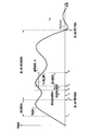
- FIG. 2 shows the flow of the panning operation in this apparatus. Specifically, the state of temporal transition of the rotational angular velocity component detected corresponding to the direction in which the camera is moved during panning is shown.
- the camera body 1 has an angular velocity ⁇ in the yaw direction.
- the angular velocity ⁇ is biased with respect to a stationary reference angular velocity ⁇ zero that is an angular velocity when the camera is stationary.
- an angular velocity that cannot be generated by camera shake during normal hand-held shooting is set as a threshold value TH, for example.
- the threshold value TH is a value used as a condition for determining that the panning is started when the angular velocity ⁇ generated in the camera body 1 exceeds the threshold value TH for a predetermined period.
- the angular velocity in the pitch direction detected in the tilting operation in which the camera is rotated in the vertical direction is not limited to this.
- deviation occurs with respect to the reference angular velocity in the pitch direction.
- the detection period A from the time t1 when the angular velocity ⁇ generated in the camera body 1 exceeds the threshold value TH in FIG. It is determined that the panning has been started from the time t2. Thereafter, when the angular velocity ⁇ generated in the camera body 1 falls below the stationary reference angular velocity ⁇ zero, this state is defined as a zero-crossing state. It is detected that the panning has been completed at time t7 when the zero crossing occurs. Thus, the panning detection period B is from the period t2 to t7.
- the angular velocity ⁇ in the angle detection period F that goes back from the exposure start time t5 to a predetermined time, for example, from the time t5 to the time t3, is time-integrated to perform yaw and pitch directions.
- the movement angle is acquired.
- the tilt angle of the camera body 1 is detected from the movement angles in the yaw direction and the pitch direction.
- the tilt of the camera body 1 is the difference between the actual swing direction of the camera body 1 and the direction in which the camera body 1 detects the angular velocity ⁇ . For example, when the camera body 1 is shaken in the left-right direction (X-axis direction), how many times it is deviated from the yaw direction.
- the average value of the angular velocity ⁇ is calculated in the velocity detection period H from the exposure start time t5 to a time point t4 that is a predetermined period backward. Panning used for correction during exposure from the angular velocity ⁇ detected in the angle detection period F from time t3 to time t5 and the average value of angular velocity ⁇ detected in the speed detection period H from time t4 to time t5 Angular velocity ⁇ pan or tilting angular velocity ⁇ til is calculated.
- a case where the camera is panned in the panning direction will be described as an example.
- the exposure period P is from the exposure start time t5 to the time point t6.
- the exposure start time t5 is when the release switch 9 is pressed.
- the panning angular velocity ⁇ pan is maintained, and the difference between the panning angular velocity ⁇ pan and the angular velocity ⁇ detected by the angular velocity sensor 8 is integrated, and the blurring during panning shown in FIG.
- a correction amount G is calculated.
- the area of the shaded area corresponds to the shake correction amount G at the time of panning.
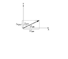
- FIG. 3 shows an example of a change in time with respect to the result of time integration of the angular velocity ⁇ in the yaw direction and pitch direction of the camera body 1.
- the horizontal axis is time
- the vertical axis is the amount of movement.
- ⁇ yaw indicates the time integration result for the angular velocity ⁇ yaw in the yaw direction.
- the value of the time integration result corresponds to an angle (defined as a panning angle) moved in the yaw direction at the time of panning shooting.
- ⁇ pitch on the other side indicates the result of time integration of the angular velocity ⁇ pitch in the pitch direction. This result corresponds to an angle (defined as a tilting angle) that is moved in the pitch direction during panning shooting.
- angular velocities ⁇ yaw and ⁇ pitch are generated in both the yaw direction and the pitch direction, respectively.
- the angles ⁇ yaw and ⁇ pitch corresponding to the deviation of the detected direction of the angular velocity ⁇ from the detected direction of the angular velocity ⁇ and the direction in which the camera body 1 is actually shaken are obtained by the ratio of the results of time integration of the angular velocities ⁇ yaw and ⁇ pitch.
- ⁇ pitch ⁇ pitch / ⁇ yaw ⁇ ⁇ yaw (3)
- angular velocity ⁇ yaw in the yaw direction from the angular velocity in the pitch direction can be obtained by the following relational expression (4).
- ⁇ yaw ⁇ yaw / ⁇ pitch ⁇ ⁇ pitch (4)
- the angular velocity ⁇ in the direction in which the camera body 1 is vibrated strongly and the angular deviation caused by the ratio of the integral values of the angular velocities in the yaw direction and the pitch direction are the same direction.
- the angular velocity ⁇ of the orthogonal direction component is calculated.
- the angular velocity ⁇ in the direction in which the camera body 1 is strongly shaken is greatly influenced by the swing due to the panning operation, and the influence of camera shake is small.
- the angular velocity ⁇ due to the swing of the panning operation that occurs in the orthogonal direction is obtained.
- the direction in which the camera body 1 is shaken is accurately obtained.
- FIG. 5 shows a block diagram of the overall configuration of the apparatus.
- the camera body 1 includes an optical system 2, a focal plane shutter 3, an image sensor 4, a drive unit 5, a system controller (control unit) 6, and a shake correction microcomputer (hereinafter abbreviated as a shake correction microcomputer) 7. And an angular velocity sensor 8, a release SW 9, an electronic viewfinder (EVF) 11, and a memory card 12 as a storage medium.
- a shake correction microcomputer hereinafter abbreviated as a shake correction microcomputer
- the optical system 2 forms an external light beam incident from a direction along the optical axis L on the image plane of the image sensor 4 as a subject image.
- the focal plane shutter 3 is disposed in front of the image pickup device 4 and opens and closes the image pickup device 4 by opening and closing.
- the imaging device 4 converts the subject image formed on the imaging surface into an electrical signal based on an instruction from the system controller 6 and reads out the converted electrical signal as a video signal.
- the system controller 6 performs various controls related to the functions of the entire camera. As a basic function of the camera, the system controller 6 reads a video signal from the image sensor 4, converts the read video signal into an image signal that can be displayed on the EVF 11, displays the image on the EVF 11, and detects from the release SW 9. Based on the above, the video signal read out at the time of photographing is recorded in the memory card 12 as a photographed image. The system controller 6 communicates with the shake correction microcomputer 7. The system controller 6 has various other functions, but only control relevant to the present invention will be described here.
- the EVF 11 includes a liquid crystal panel.
- the EVF 11 displays the image on the liquid crystal panel so that the user can visually recognize the video signal output from the system controller 6.
- the release switch SW9 detects each release operation of half-press (1st release) and full-press (2nd release), which is an operation when the user performs a shooting operation, and outputs a detection signal of these release operations to the system controller 6.
- the memory card 12 is a non-volatile memory for recording captured images. The memory card 12 is detachable from the camera body 1.
- the driving unit 5 supports the image sensor 4 and moves and drives the image sensor 4 in the X-axis direction and the Y-axis direction based on an instruction issued from the shake correction microcomputer 7.
- the angular velocity sensor 8 detects, for example, each rotational motion in the yaw direction and the pitch direction.
- the angular velocity sensor 8 includes, for example, a yaw angular velocity sensor (first angular velocity detection unit) 8a and a pitch angular velocity sensor (second angular velocity detection unit) 8b provided in different mounting directions.
- the yaw angular velocity sensor 8a detects the first angular velocity when rotating in the yaw direction with the first vertical direction as the first axis with respect to the direction of the optical axis L of the optical system 2.
- the yaw angular velocity sensor 8 a detects the angular change in the yaw direction as the angular velocity ⁇ yaw, and outputs an analog angular velocity detection signal to the blur correction microcomputer 7.
- the pitch angular velocity sensor 8b detects a second angular velocity when rotating in the pitch direction with a direction orthogonal to both the optical axis L and the first axis as a second axis.
- the pitch angular velocity sensor 8 b detects an angular change in the pitch direction as an angular velocity ⁇ pitch, and outputs an analog angular velocity detection signal to the shake correction microcomputer 7.
- a roll angular velocity sensor that detects an angular change in the roll direction as an angular velocity ⁇ roll may be provided.
- the shake correction microcomputer 7 calculates the shake amount generated on the imaging surface from the angular velocity detection signals output from the angular velocity sensor 8 in the yaw direction and the pitch direction, and cancels these shake amounts.
- a drive instruction for moving in the direction that is, a drive instruction corresponding to the shake correction amount G shown in FIG. Therefore, since the drive unit 5 drives the image sensor 4 in a direction that cancels out the blur on the image plane, the blur that occurs in the captured image is prevented.
- the drive unit 5 drives the image sensor 4 in a direction to cancel out the blur, but may drive the optical system 2.
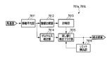
- FIG. 6 shows a block diagram of the internal configuration of the blur correction microcomputer 7.
- the blur correction microcomputer 7 includes a CPU 70, two ADCs 71a and 71b, an SIO 72, and two drivers 73a and 73b.
- the CPU 70 includes, as processing functions of a control program for performing shake correction control therein, reference calculation units 74a and 74b, two subtraction units 75a and 75b, a panning control unit 76, a shake correction unit 77, and a communication unit. 78.
- the two ADCs 71a and 71b each convert an analog angular velocity detection signal output from the angular velocity sensor 8 into a digital signal.
- the ADC 71a converts the angular velocity detection signal output from the yaw angular velocity sensor 8a into a digital signal.
- the ADC 71b converts the angular velocity detection signal output from the pitch angular velocity sensor 8b into a digital signal.
- Each of the ADCs 71a and 71b converts, for example, an analog angular velocity detection signal into a digital signal at a sampling rate of 1 kHz and at an interval of 1 ms.
- the sampling rate is not particularly limited to the rate value, and more accurate detection can be performed by increasing the rate.
- the sampling rate may be set to an optimum rate according to the system performance.
- the SIO 72 forms a serial interface between the CPU 70 and an external device.
- the SIO 72 performs communication between the CPU 70 and an external device, for example, exchanges commands between the CPU 70 and the system controller 6.
- the two drivers 73a and 73b output drive signals for driving the drive unit 5 based on the respective shake correction amounts G (Gy, Gp) calculated by the CPU 70, for example, in the yaw direction and the pitch direction, respectively.
- the driver 73a outputs a drive signal based on the shake correction amount G (Gy) in the yaw direction.
- the driver 73b outputs a drive signal based on the shake correction amount G (Gp) in the pitch direction.
- the CPU 70 executes a blur correction amount calculation program, takes in each angular velocity detection signal output from each angular velocity sensor 8a, 8b, and outputs the angular velocity detection signals in the yaw direction and the pitch direction, and generates the yaw direction generated on the imaging surface of the image sensor 4. And a shake correction amount G for moving and driving in the direction opposite to the shake amount is calculated.
- a program for calculating a shake correction amount is transmitted in the yaw direction to a CPU 70 of an imaging apparatus including an optical system 2 that forms an image of a subject and an imaging device 4 that outputs an image signal from an optical image formed by the optical system 2.
- the reference calculation unit 74a takes in the angular velocity detection signal output from the angular velocity sensor 8a in the yaw direction, and obtains the value of the angular velocity ⁇ yaw in a state where the rotational motion in the yaw direction is stopped as a reference value.
- the reference calculation unit 74b takes in the angular velocity detection signal output from the angular velocity sensor 8b in the pitch direction, and obtains the value of the angular velocity ⁇ pitch when the rotational motion in the pitch direction is stopped as a reference value.
- the purpose of calculating the reference values (stationary angular velocity reference values) of the angular velocities ⁇ yaw and ⁇ pitch at rest is as follows.
- the output of angular velocity detection detected by the stationary angular velocity sensor is essentially zero, but actually, the sensor output may include a DC component offset component. Accordingly, in order to detect the correct angular velocity, the compensation is performed by subtracting the stationary angular velocity reference value corresponding to the offset component from the actually detected angular velocity value.
- the stationary angular velocity reference value in both the yaw direction and the pitch direction can be calculated by taking an average value for a sufficiently long period (about several seconds), but is not limited to this, and may be obtained by various methods. For example, the same effect can be obtained by LPF (Low Pass Filter) processing that extracts only the low frequency component of the angular velocity signal. A similar effect can be obtained by removing the DC component from the angular velocity detection signal by HPF (High Pass Filter) processing that extracts only the AC signal component including the subtractors 75a and 75b.
- LPF Low Pass Filter
- HPF High Pass Filter
- the two subtraction units 75a and 75b subtract the reference values calculated by the reference calculation units 74a and 74b from the angular velocity detection signals output from the angular velocity sensors 8a and 8b, respectively.
- the subtraction unit 75a subtracts the reference value in the yaw direction calculated by the reference calculation unit 74a from the angular velocity detection signal (angular velocity ⁇ yaw) output from the angular velocity sensor 8a in the yaw direction.
- the subtracting unit 75b subtracts the reference value in the pitch direction calculated by the reference calculating unit 74b from the angular velocity detection signal (angular velocity ⁇ pitch) output from the angular velocity sensor 8b in the pitch direction.
- the angular velocities ⁇ yaw and ⁇ pitch become angular velocities having signs (+, ⁇ ), respectively.
- the sign (+, ⁇ ) can be handled as the rotation direction of the detected angular velocities ⁇ yaw and ⁇ pitch.
- the panning control unit 76 determines whether or not the camera is in the panning state based on the angular velocity ⁇ yaw in the yaw direction detected by the yaw angular velocity sensor 8a and the angular velocity ⁇ pitch in the pitch direction detected by the pitch angular velocity sensor 8b. .
- the panning control unit 76 outputs the subtraction signal in the yaw direction output from the subtraction unit 75a, that is, the angular velocity ⁇ yaw having the sign (+, ⁇ ), and the subtraction signal in the pitch direction output from the subtraction unit 75b, that is, the sign ( The angular velocity ⁇ pitch having +, ⁇ ) is taken in, and it is determined that the panning is started based on these angular velocities ⁇ yaw and ⁇ pitch.
- the panning control unit 76 when shooting is started during the panning detection, corrects angular velocities obtained by removing the panning angular velocity ⁇ pan and tilting angular velocity ⁇ til related to panning from the angular velocities ⁇ yaw and ⁇ pitch. Outputs ⁇ stabyaw and ⁇ stabpitch.
- the shake correction unit 77 integrates the corrected angular velocities ⁇ stabyaw and ⁇ stabpitch output from the panning control unit 76 to obtain respective angle changes, and the imaging surface of the image sensor 4 from these angle changes and the focal length of the optical system 2. Is calculated. Then, the shake correction unit 77 obtains a shake correction amount G (Gy, Gp) between the yaw direction and the pitch direction for canceling out the shake amount, and issues a drive instruction corresponding to these shake correction amounts G (Gy, Gp). The signals are emitted to the drive unit 5 via the drivers 73a and 73b, respectively. Since there are various calculation methods for calculating the shake correction amount G (Gy, Gp), any one of the calculation methods may be used.
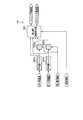
- FIG. 7 shows a specific block diagram of the panning control unit 76.
- the panning control unit 76 includes two panning detections 761a and 761b, a panning angular velocity calculation unit 762, and two subtraction units 763a and 763b.
- the panning detection unit 761a receives the angular velocity ⁇ yaw in the yaw direction having the sign (+, ⁇ ) output from the subtraction unit 75a, and detects the angular velocity ⁇ yaw based on the angular velocity ⁇ yaw as shown in FIG. It is confirmed whether or not the threshold value TH has been exceeded for the period A, and it is detected whether a panning operation is being performed.
- the panning detection unit 761b receives the angular velocity ⁇ pitch in the pitch direction having the sign (+, ⁇ ) output from the subtraction unit 75b, and detects the angular velocity ⁇ pitch based on the angular velocity ⁇ pitch, as shown in FIG. It is confirmed whether or not the threshold value TH has been exceeded for the period A, and it is detected whether a panning operation is being performed.
- the panning angular velocity calculation unit 762 is based on the angular velocities ⁇ yaw and ⁇ pitch of a predetermined period immediately before the shooting.
- a panning angular velocity ⁇ pan in the yaw direction and a tilting angular velocity ⁇ til in the pitch direction generated by the panning are calculated.
- the subtraction unit 763a receives the angular velocity ⁇ yaw in the yaw direction having the sign (+, ⁇ ) output from the subtraction unit 75a, and the panning angular velocity calculated by the panning angular velocity calculation unit 762 from the angular velocity ⁇ yaw in the yaw direction.
- the angular velocity to be corrected that is, the corrected angular velocity ⁇ stabyaw in the yaw direction is calculated by subtracting ⁇ pan.
- the subtracting unit 763b receives the angular velocity ⁇ pitch in the pitch direction having the sign (+, ⁇ ) output from the subtracting unit 75b, and the panning angular velocity calculated by the panning angular velocity calculating unit 762 from the angular velocity ⁇ pitch in the pitch direction.
- the angular velocity to be corrected that is, the corrected angular velocity ⁇ stabpitch is calculated by subtracting ⁇ til.
- each panning detection unit 761a and 761b has the same configuration, and is a moving average unit 7611, a threshold comparison unit 7612, a timing unit 7613, a zero cross detection unit 7614, a panning detection detection flag unit 7615, and a limit. And a detection unit 7616.
- the moving average unit 7611 sequentially inputs the angular velocity ⁇ yaw in the yaw direction having the sign (+, ⁇ ) output from the subtracting unit 75a, and in the yaw direction based on a plurality of sampling values immediately before each angular velocity ⁇ yaw.
- the moving average value Ave ⁇ yaw of the angular velocity ⁇ yaw is calculated.
- the moving average unit 7611 sequentially inputs the angular velocity ⁇ pitch in the pitch direction having the sign (+, ⁇ ) output from the subtracting unit 75b, and in the pitch direction based on a plurality of sampling values immediately before each angular velocity ⁇ pitch.
- the moving average value Ave ⁇ pitch of the angular velocity ⁇ pitch is calculated.
- the moving average unit 7611 may not be provided, but even if noise due to various external factors such as an impact during the operation of the shutter occurs, the moving average unit 7611 is provided to stably detect the panning. can do.
- the threshold comparison unit 7612 compares the moving average value Ave ⁇ yaw of the angular velocity ⁇ yaw in the yaw direction calculated by the moving average unit 7611 with the threshold TH in the yaw direction, and the moving average value Ave ⁇ yaw of the angular velocity ⁇ yaw in the yaw direction is the threshold in the yaw direction. It is determined whether or not TH is exceeded.
- the threshold comparison unit 7612 compares the moving average value Ave ⁇ pitch of the angular velocity ⁇ pitch in the pitch direction calculated by the moving average unit 7611 with the threshold TH of the pitch direction, and the moving average value Ave ⁇ pitch of the angular velocity ⁇ pitch in the pitch direction is the threshold in the pitch direction.
- Each threshold value TH in the yaw direction and the pitch direction is set to an angular velocity ⁇ that does not occur in normal hand-held shooting of, for example, about 10 deg / s, but this angular velocity ⁇ may be a fixed value or the optical system 2. By changing the focal length or the like, detection suitable for the shooting angle of view can be performed.
- the time measuring unit 7613 determines that the moving average value Ave ⁇ yaw of the angular velocity ⁇ yaw in the yaw direction or the moving average value Ave ⁇ pitch of the angular velocity ⁇ pitch in the pitch direction exceeds the threshold values TH in the yaw direction and the pitch direction, respectively, based on the comparison result by the threshold value comparing unit 7612. Measure the determined period. Then, the time measuring unit 7613 determines whether or not the measurement period exceeds a predetermined detection period A. When the measurement period exceeds the detection period A, it is determined that the panning has started from the time when the measurement period exceeds the detection period A. To detect.
- the zero-cross detection unit 7614 receives the moving average value Ave ⁇ yaw of the angular velocity ⁇ yaw in the yaw direction or the moving average value Ave ⁇ pitch of the angular velocity ⁇ pitch in the pitch direction calculated by the moving average unit 7611 and receives the average value Ave ⁇ yaw or the pitch of the angular velocity ⁇ yaw in the yaw direction. It is determined whether or not the moving average value Ave ⁇ pitch of the angular velocity ⁇ pitch in the direction has crossed zero. In the determination of zero cross, the zero average is determined by either the sign (+, ⁇ ) of the moving average values Ave ⁇ yaw and Ave ⁇ pitch of the angular velocity being inverted or the value “0”.
- the panning detection flag unit 7615 sets a flag (a panning detection flag) at the time of detection when the timer 7613 detects the start of the panning, and detects the zero cross when the zero cross detection unit 7614 detects the zero cross. Sometimes clear the panning flag. That is, the panning detection period B is from when the panning flag is set to when it is cleared, and during the period B, the panning operation is being performed.
- the limit detection unit 7616 performs a time counting operation during the panning detection period B in which the panning flag is set, and clears the panning detection flag when the timed period of the time counting operation exceeds a predetermined period. Accordingly, for example, even when an incorrect reference is calculated in the reference calculation units 74a and 74b, it is possible to prevent the state that is erroneously detected as panning from being continued.
- the reference velocity calculation unit 762 includes two average value buffers 7621a and 7621b, two integration units 7622a and 7622b, and a panning angular velocity calculation 7623.
- the average value buffer 7621a receives the angular velocity ⁇ yaw in the yaw direction having the sign (+, ⁇ ) output from the subtractor 75a, and holds a plurality of average values for a predetermined period of the angular velocity ⁇ yaw. For example, the average value buffer 7621a holds 8 data of an average value of 8 periods every 8 periods from the latest.
- the moving average unit 7621b receives the angular velocity ⁇ pitch in the pitch direction having the sign (+, ⁇ ) output from the subtracting unit 75b, and holds a plurality of average values for a predetermined period of the angular velocity ⁇ pitch.
- Each of the average value buffers 7621a and 7621b holds 8 data of an average value of 8 periods every 8 periods from the latest, but is not limited to this, and other data numbers may be used.
- the integration unit 7622a sequentially acquires and integrates eight data of average values calculated and held by the average value buffer 7621a.
- the integration unit 7622b sequentially acquires and integrates eight data of average values calculated and held by the average value buffer 7621b.
- the average values Ave ⁇ yaw and Ave ⁇ pitch of the angular velocities ⁇ yaw and ⁇ pitch in the yaw direction and the pitch direction are the average values of the latest eight data of the angular velocities ⁇ yaw and ⁇ pitch.
- the latest 16 data can be obtained by using data every 8 cycles, and the ratio of the integral values of the angular velocities ⁇ yaw and ⁇ pitch in the yaw direction over a long period can be obtained with a small number of data.
- the period for obtaining the ratio is for obtaining the ratio between the yaw direction angular velocity ⁇ yaw and the pitch direction angular velocity ⁇ pitch by removing the influence of camera shake, and may be any period in which the camera shake component can be removed.
- the panning angular velocity calculation 7623 calculates the relationship between the ratio between the integral value of the angular velocity ⁇ yaw in the yaw direction calculated by the integrating unit 7622a and the integrated value of the angular velocity ⁇ pitch in the pitch direction calculated by the integrating unit 7622b and the absolute value.
- the panning angular velocity in the yaw direction and the tilting angular velocity in the pitch direction are calculated.
- the integral value of the angular velocity ⁇ yaw in the yaw direction is compared with the integral value of the angular velocity ⁇ pitch in the pitch direction, and the direction corresponding to the integral value having a large absolute value among these integral values. That is, the other angular velocity is calculated based on the angular velocity in the direction in which the camera body 1 is strongly shaken in the yaw direction or the pitch direction. In this way, the angular velocities ⁇ pan and ⁇ til due to panning or tilting without the influence of camera shake can be accurately calculated.
- the panning angular velocity calculation unit 7623 pans the latest average value of the angular velocity ⁇ yaw in the yaw direction output from the average value buffer 7621a in the yaw direction. Output as angular velocity ⁇ pan.
- the panning angular velocity calculation unit 7623 calculates the latest average value of the angular velocity ⁇ yaw in the yaw direction output from the average value buffer 7621a, the integrated value of the angular velocity ⁇ yaw in the yaw direction, and the integrated value of the angular velocity ⁇ pitch in the pitch direction. From the above, the tilting angular velocity ⁇ til in the pitch direction is calculated based on the above equation (3).
- the panning angular velocity calculation unit 7623 uses the latest average value of the angular velocity ⁇ pitch in the pitch direction output from the average value buffer 7621b as it is in the pitch direction. Used as angular velocity ⁇ til. Regarding the yaw direction, the panning angular velocity calculation unit 7623 calculates the latest average value of the angular velocity ⁇ pitch in the pitch direction output from the average value buffer 7621b, the integrated value of the angular velocity ⁇ yaw in the yaw direction, and the integrated value of the angular velocity ⁇ pitch in the pitch direction. From the above, the panning angular velocity ⁇ pan in the yaw direction is calculated based on the above equation (4).
- FIG. 10 is a flowchart showing a control flow of the panning control unit.
- the moving average unit 7611 of the panning detection unit 761a sequentially inputs the angular velocities ⁇ yaw in the yaw direction having the signs (+, ⁇ ) output from the subtracting unit 75a, and a plurality of moving averages 7611a immediately before the respective angular velocities ⁇ yaw are input.
- the average value Ave ⁇ yaw of the angular velocity ⁇ yaw in the yaw direction is calculated based on the sampling values of the times.
- step S1 the moving average unit 7611 sequentially inputs the angular velocity ⁇ pitch in the pitch direction having the sign (+, ⁇ ) output from the subtracting unit 75b, and the sampling value immediately before each angular velocity ⁇ pitch is input. Based on this, the average value Ave ⁇ pitch of the angular velocity ⁇ pitch in the pitch direction is calculated.
- step S2 the zero cross detection unit 7614 receives the average value Ave ⁇ yaw of the angular velocity ⁇ yaw in the yaw direction calculated by the moving average unit 7611, and determines whether or not the average value Ave ⁇ yaw of the angular velocity ⁇ yaw in the yaw direction has zero-crossed.
- step S2 the zero cross detection unit 7614 receives the average value Ave ⁇ pitch of the angular velocity ⁇ pitch in the pitch direction calculated by the moving average unit 7611, and whether or not the average value Ave ⁇ pitch of the angular velocity ⁇ pitch in the pitch direction has zero-crossed. Determine.
- the zero cross is determined by either the sign (+, ⁇ ) of the angular velocities ⁇ yaw and ⁇ pitch being inverted or the “0” value.
- the sign (+, ⁇ ) of the average value Ave ⁇ yaw of the angular velocity ⁇ yaw in the yaw direction calculated last time and the average value Ave ⁇ yaw of the angular velocity ⁇ yaw in the yaw direction calculated this time are different, or the yaw calculated this time is related to the yaw direction.
- a zero cross flag is set on the assumption that a zero cross has occurred.
- the zero cross is the sign (+, ⁇ ) of the average value Ave ⁇ pitch of the angular velocity ⁇ pitch in the pitch direction calculated last time and the average value Ave ⁇ pitch of the angular velocity ⁇ pitch in the pitch direction calculated this time, or calculated this time.
- the average value Ave ⁇ pitch of the angular velocity ⁇ pitch in the pitch direction is “0”, a zero cross flag is set on the assumption that a zero cross has occurred.
- step S3 the panning detection unit 761a inputs the angular velocity ⁇ yaw in the yaw direction having the sign (+, ⁇ ) output from the subtraction unit 75a, and the panning operation is performed based on the angular velocity ⁇ yaw. Detect whether or not When the start of the panning is detected, the panning detection unit 761a sets a panning flag.
- step S3 the panning detection unit 761b inputs the angular velocity ⁇ pitch in the pitch direction having the sign (+, ⁇ ) output from the subtraction unit 75b, and the panning operation is performed based on the angular velocity ⁇ pitch. Detect whether or not When the start of the panning is detected, the panning detection unit 761b sets a panning flag. Details of the operations of the panning detection units 761a and 761b will be described later.
- the panning detectors 761a and 761b clear the panning flag if a factor for clearing the panning flag has occurred in step S4.
- the cause of clearing the panning flag is when the zero cross flag is set or when the panning detection flag is continuously set for a predetermined time or more.
- the predetermined time is, for example, 10 seconds, and is set to a time longer than the time for continuously performing normal panning.
- step S5 the average value of the angular velocity ⁇ yaw in the yaw direction calculated by the average value buffer 7621a of the panning angular velocity calculation unit 762 and the average value of the angular velocity ⁇ pitch in the pitch direction calculated by the average value buffer 7621b are average values.
- a predetermined number is held for each predetermined period in a buffer memory or the like included in the buffers 7621a and 7621b. For example, here, 8 data of average values every 8 cycles are held.
- step S6 the panning detectors 761a and 761b determine whether the panning flag is set or not, and determine whether it is the panning detection period B shown in FIG. If the result of this determination is the panning detection period B, the process moves to step S7 to determine whether or not the state of the apparatus (camera) is the exposure state. If it is not the panning detection period B, the process proceeds to step S11. Then, the panning angular velocity ⁇ pan in the pitch direction and the tilting angular velocity ⁇ til in the yaw direction are each cleared to “0”.
- step S8 determines in step S8 whether the state of the apparatus (camera) is the first correction start or is being corrected. Determine. As a result of this determination, if the correction process is the first correction process, the system controller 6 causes each of the integration units 7622a and 7622b to perform an integration operation in step S9.
- the integrating unit 7622a integrates the average value for 8 data held in the average value buffer 7621a.
- the integration unit 7622b integrates the average value for 8 data held in the average value buffer 7621b.
- the panning angular velocity calculating unit 7623 calculates the absolute value of the ratio between the integrated value of the angular velocity ⁇ yaw in the yaw direction calculated by the integrating unit 7622a and the integrated value of the angular velocity ⁇ pitch in the pitch direction calculated by the integrating unit 7622b. Find the magnitude relationship between values.
- the panning angular velocity calculation unit 7623 calculates a panning angular velocity ⁇ pan in the yaw direction, which is an angular velocity associated with panning in the yaw direction and the pitch direction, and a panning angular velocity ⁇ pitch in the tilting direction.
- step S12 the subtracting unit 763a inputs the angular velocity ⁇ yaw in the yaw direction having the sign (+, ⁇ ) output from the subtracting unit 75a, and is calculated by the angular velocity ⁇ yaw in the yaw direction and the panning angular velocity calculating unit 762.
- the yaw correction angular velocity to be corrected is calculated by subtracting it from the panning angular velocity ⁇ pan in the yaw direction.
- step S12 the subtraction unit 763b receives the angular velocity ⁇ pitch in the pitch direction having the sign (+, ⁇ ) output from the subtraction unit 75b, and the angular velocity ⁇ pitch in the pitch direction and the panning angular velocity calculation unit 762 A pitch correction angular velocity to be corrected is calculated by subtracting the calculated tilting angular velocity ⁇ til in the pitch direction.
- the blur correction unit 77 calculates a correction amount by integrating the obtained yaw correction angular velocity and pitch correction angular velocity, and corrects and drives the drive unit 5 according to these correction amounts, thereby removing the angular velocity associated with panning. Only the amount of camera shake is corrected. When no panning is detected, the panning angular velocity ⁇ pan and the tilting angular velocity ⁇ til are both 0, so the system controller 6 functions as normal camera shake correction.
- step S3 the panning detectors 761a and 761b determine whether or not the panning is being performed by determining whether or not the panning flag is set.
- the panning flag is set by the panning detection flag unit 7615.
- the panning detection units 761a and 761b pass through the main panning detection process.
- the threshold comparison unit 7612 calculates the average value of the angular velocity ⁇ yaw in the yaw direction calculated by the moving average unit 7611 and the threshold value TH in the yaw direction in step S32 as shown in FIG. To determine whether the average value Ave ⁇ yaw of the angular velocity ⁇ yaw in the yaw direction exceeds the threshold value TH in the yaw direction.
- step S33 the time measuring unit 7613 calculates the average value Ave ⁇ yaw of the angular velocity ⁇ yaw in the yaw direction or the angular velocity ⁇ pitch in the pitch direction.
- a counter for measuring the determined period t1-t2 is counted up. The timer unit 7613 counts up the counter and measures the detection period A shown in FIG.
- the time measuring unit 7613 clears the measured value of the counter in the corresponding direction to “0” in step S34.
- step S35 the time measuring unit 7613 determines whether or not the counted up measurement period t1-t2 has exceeded a predetermined detection period A. As a result of this determination, when the measurement period t1-t2 exceeds the predetermined detection period A, the panning detection flag unit 7615 at time t2 when the measurement period exceeds the predetermined detection period A in step S36. Raise the panning detection flag.
- step S37 the limit detection unit 7616 clears the panning detection flag when the time period measured by the time measuring operation of the time measuring unit 7613 exceeds a predetermined period.
- the limit detection unit 7616 clears the panning flag at the time t7 when the zero cross is detected.
- the panning detection period B is from the time t2 when the panning flag is set to the time t7 when it is cleared. In the panning detection period B, the panning operation is being performed.
- the specific operation of the panning angular velocity calculation process (step S10) will be described with reference to the block diagram of the panning angular velocity calculation unit 762 shown in FIG.
- step S91 the panning angular velocity calculation unit 7623 obtains absolute values
- the panning angular velocity calculation unit 7623 is assumed to be panning while the camera body 1 is shaken predominantly in the yaw direction.
- the average value Ave ⁇ yaw of the angular velocity ⁇ yaw in the yaw direction is set as the panning angular velocity ⁇ pan in the yaw direction.
- step S93 the panning angular velocity calculation unit 7623 calculates the tilting angular velocity ⁇ til in the pitch direction based on the average value Ave ⁇ yaw of the angular velocity ⁇ yaw in the yaw direction and the angular velocity ⁇ pitch in the pitch direction shown in the above equation (3). That is, the panning angular velocity calculating unit 7623 calculates the following equation (6) to calculate the tilting angular velocity ⁇ til in the pitch direction.
- ⁇ til Ave ⁇ yaw ⁇ ( ⁇ Ave_ ⁇ pitch / ⁇ Ave_ ⁇ yaw)... (6)
- the average value Ave ⁇ pitch of the angular velocity ⁇ pitch in the pitch direction is set as the tilting angular velocity ⁇ til in the pitch direction.
- step S95 the panning angular velocity calculation unit 7623 calculates the panning angular velocity ⁇ pan in the yaw direction based on the average value Ave ⁇ pitch of the angular velocity ⁇ pitch in the pitch direction and the angular velocity ⁇ yaw in the yaw direction shown in the above equation (4). That is, the panning angular velocity calculation unit 7623 calculates the following angular expression (7) to calculate the reference angular velocity ⁇ pan in the yaw direction.
- ⁇ pan Ave ⁇ pitch ⁇ ( ⁇ Ave_ ⁇ yaw / ⁇ Ave_ ⁇ pitch)... (7)
- the subtractor 763a subtracts the angular velocity ⁇ yaw in the yaw direction output from the subtractor 75a and the panning angular velocity ⁇ pan in the yaw direction calculated from the above, and the angular velocity to be corrected, that is, the yaw correction Calculate angular velocity.
- the subtracting unit 763b subtracts the angular velocity ⁇ pitch in the pitch direction output from the subtracting unit 75b and the tilting angular velocity ⁇ til in the pitch direction calculated from the above to calculate the angular velocity to be corrected, that is, the pitch corrected angular velocity. .
- the blur correction unit 77 integrates the yaw correction angular velocity and the pitch correction angular velocity output from the panning control unit 76 to obtain respective angle changes, and takes an image of the image sensor 4 from these angle changes and the focal length of the optical system 2. Calculate the amount of blurring on the surface.
- the shake correction unit 77 obtains each shake correction amount G (Gy, Gp) in the yaw direction and the pitch direction for canceling out the shake amount, and issues a drive instruction corresponding to the shake correction amount G (Gy, Gp).
- the signals are emitted to the drive unit 5 via the drivers 73a and 73b, respectively.
- the drive unit 5 moves and drives the image sensor 4 in the X-axis direction and the Y-axis direction based on the drive instruction corresponding to each blur correction amount G (Gy, Gp) in the yaw direction and the pitch direction. Blur that occurs on the imaging surface of the imaging element 4 is corrected.
- the panning angular velocity ⁇ pan of the angular velocity ⁇ yaw in the yaw direction is calculated based on the output signal from the angular velocity sensor 8a, and the yaw direction is calculated.
- the panning angular velocity ⁇ pan in the direction and the angular velocity ⁇ yaw in the yaw direction are subtracted to calculate the blur correction amount G (Gy) in the yaw direction.
- the angular velocity in the pitch direction is also calculated in the pitch direction based on the output signal from the angular velocity sensor 8b.
- the tilting angular velocity ⁇ til of ⁇ pitch is calculated, the tilting angular velocity ⁇ til in the pitch direction and the angular velocity ⁇ pitch in the pitch direction are subtracted, and the blur correction amount G (Gp) in the pitch direction is calculated, and these yaw direction and pitch direction
- the image sensor 4 is moved and driven in the X-axis direction and the Y-axis direction by issuing a drive instruction corresponding to the shake correction amount G (Gy, Gp).
- the average value ⁇ Ave_ ⁇ yaw of the average value of the angular velocity ⁇ yaw in the yaw direction and the integral value ⁇ Ave_ ⁇ pitch of the average value of the angular velocity ⁇ pitch in the pitch direction
- the panning angular velocity ⁇ pan in the yaw direction is the average value Ave ⁇ yaw of the angular velocity ⁇ yaw in the yaw direction
- the tilting angular velocity ⁇ til in the pitch direction is Calculation is performed by calculating equation (6).
- the tilting angular velocity ⁇ til in the pitch direction is the average value of the angular velocity ⁇ pitch in the pitch direction
- the reference angular velocity ⁇ til in the yaw direction is the above formula (7) Is calculated.
- the panning angular velocity ⁇ pan and the tilting angular velocity ⁇ til between the yaw direction and the pitch direction are calculated based on the angular velocity ⁇ immediately before imaging, and the image plane of the image sensor 4 is exposed during the exposure period P.
- the generated movement amount of the subject is corrected so that the movement amount is based on the panning angular velocity ⁇ pan and the tilting ⁇ til between the yaw direction and the pitch direction.
- the camera body 1 is not affected by variations in the swing speed of the camera body 1, and the camera body 1 can be tilted even if the detection direction of the angular velocity ⁇ and the swing direction of the camera body 1 are tilted. Since the blurring in the direction perpendicular to the swing direction can also be corrected, the probability of successful panning can be improved.
- the amount of movement of the subject image generated on the image plane of the image sensor 4 is constant even when the camera shake speed is not constant at the time of panning shooting by an imaging device such as a camera. Furthermore, even when the camera shake direction is inclined with respect to either the pitch direction or the yaw direction, that is, when the camera is shaken in a two-dimensional direction, the shake in the direction orthogonal to the swing direction can be prevented. It is possible to relax, improve the success rate of panning, and reduce the technical difficulty of panning.
- FIGS. 13A and 13B show live images displayed on the EVF 11 in a state in which the camera body 1 is chased.
- a continuous frame picture of a view picture is shown.
- the live view video is read by the system controller 6 in real time and subjected to image processing by photoelectrically converting the subject image formed on the image sensor 4 while the camera is in a shooting standby state and the focal plane shutter 3 is opened. Is displayed on the EVF 11.
- FIG. 13C shows the movement of the subject 100 between frames.
- the vectors ⁇ x and ⁇ y are detected from the amount of movement between frames.
- the vector ⁇ X indicates the amount of movement in the X-axis direction on the imaging surface of the imaging element 4.
- the vector ⁇ y indicates the amount of movement in the Y-axis direction on the imaging surface of the imaging element 4.
- the angle ⁇ yaw in the yaw direction and the angle ⁇ pitch in the pitch direction are changes in the angle between frames detected by the angular velocity sensor 8 (yaw angular velocity sensor 8a, pitch angular velocity sensor 8b).
- a state where the camera body 1 is swung in the direction of the angle ⁇ pan is shown by the angle ⁇ yaw in the yaw direction and the angle ⁇ pitch in the pitch direction.
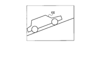
- FIG. 13D shows a state in which the camera body 1 is viewed from the back when the subject 100 such as the vehicle body that moves in parallel shown in FIGS. 13A and 13B is imaged.
- the panning operation is performed with the camera body 1 tilted in the detection direction of the angular velocity ⁇ .
- FIG. 13E is a schematic diagram in which the moving direction of the subject 100 when the camera body 1 is panned with the inclination in the detection direction of the angular velocity ⁇ as shown in FIG. 13A is converted into the horizontal direction. The figure is shown.
- a vector ⁇ target shown in FIG. 13E is a value obtained by converting the moving direction of the subject 100 and the speed of the subject 100 into an angle change of the camera body 1. If the speed at which the camera body 1 is shaken and the speed of the subject 100 do not correspond to each other as shown in FIG. 13C, the image captured by the image sensor 4 appears as a moving amount of blurring of the image of the subject 100.
- the focal length f at the time of shooting can be converted into an angle change by the following equations (8) and (9).
- ⁇ D f ⁇ tan ⁇ (8)
- ⁇ atan ( ⁇ D / f) (9)
- ⁇ D Movement amount f: Focal length
- T T is a time period between frames determined by the frame rate
- the angular velocity ⁇ c can be obtained by the following equation (10).
- ⁇ c ⁇ / T (10)
- the difference between the calculated angular velocities ⁇ x and ⁇ y and the detected angular velocities ⁇ yaw and ⁇ pitch is taken to correct the panning angular velocities ⁇ pan and tilting angular velocities ⁇ til so that the speed of shaking the camera body 1 is changed.
- the angular velocities ⁇ x and ⁇ y calculated between the frames of the subject 100 are used, and the deviation of the subject image on the imaging surface of the image sensor 4 is corrected by correcting the deviation with respect to the panning angular velocity ⁇ pan and the tilting angular velocity ⁇ til. Can be eliminated.
- FIG. 5 to FIG. 9 are used, and the same reference numerals are given to the same portions as those of the first embodiment. The detailed explanation will be omitted, and the differences will be explained.
- the system controller 6 While displaying the live view video, the system controller 6 detects the subject 100 near the center within the shooting angle of view, and calculates the amount of movement of the subject 100 between frames. There are already various methods for calculating the amount of movement, and either method may be used.
- the system controller 6 calculates the amount of movement of the subject 100 in the X-axis direction and the amount of movement in the Y-axis direction with respect to the imaging surface of the image sensor 4, and blur correction of each movement amount in the X-axis and Y-axis directions by serial communication. Notify the microcomputer 7 for each frame.
- the blur correction microcomputer 7 receives the movement amounts in the X-axis and Y-axis directions by the communication unit 78 via the SIO 72.
- FIG. 14 shows a specific block diagram of the panning control unit 76.
- the angle conversion unit 764a calculates the angular velocity ⁇ x converted into the yaw direction by calculating the above equations (9) and (10) based on the movement amount in the X-axis direction.
- the angle conversion unit 764b calculates the angular velocity ⁇ y converted into the pitch direction by calculating the above formulas (9) and (10) based on the movement amount in the Y-axis direction.
- the subtractor 763c subtracts the angular velocity ⁇ x converted in the yaw direction from the panning angular velocity ⁇ pan in the yaw direction calculated by the offset detector 762.
- the subtracting unit 763d subtracts the angular velocity ⁇ y converted in the pitch direction from the tilting angular velocity ⁇ til in the pitch direction calculated by the reference velocity calculating unit 762.
- FIG. 15 shows a reference angular velocity calculation start flowchart.
- the angle conversion unit 764a calculates the angular velocity ⁇ x converted into the yaw direction by calculating the above equations (6) and (7) based on the movement amount in the X-axis direction.
- the angle conversion unit 764a calculates the angular velocity ⁇ x using ⁇ X and ⁇ Y as the movement amounts between frames notified from the system controller 6, but in this embodiment, the frame rate of the live view is 60 fps (frame per second).
- the calculated angular change is multiplied by 60, which is 60 fps, to obtain the angular velocity ⁇ x.
- ⁇ x atan ( ⁇ X / f) ⁇ 60 (11)
- the angle conversion unit 764b calculates the angular velocity ⁇ y converted into the pitch direction by calculating the above formulas (6) and (7) based on the movement amount in the Y-axis direction. Also in the calculation of the angular velocity ⁇ y, since the frame rate of the live view is set to 60 fps, the calculated angular change is multiplied by 60, which is 60 fps, to obtain the angular velocity ⁇ y.
- step S93 the panning angular velocity calculation unit 7623 performs tilting in the pitch direction based on the average value of the angular velocity ⁇ yaw in the yaw direction, the angular velocity ⁇ pitch in the pitch direction shown in the above equation (3), and the angular velocity ⁇ y.
- the angular velocity ⁇ til is calculated. That is, the reference angular velocity calculation unit 7623 calculates the reference angular velocity ⁇ til in the pitch direction by calculating the following equation (13).
- ⁇ til Ave ⁇ yaw ⁇ ( ⁇ Ave_ ⁇ pitch / ⁇ Ave_ ⁇ yaw) ⁇ y (13)
- the panning angular velocity calculation unit 7623 determines the average value Ave ⁇ pitch of the angular velocity ⁇ pitch in the pitch direction and the yaw direction shown in the above equation (4).
- the panning angular velocity ⁇ pan in the yaw direction is calculated based on the angular velocity ⁇ yaw and the angular velocity ⁇ x.
- the panning angular velocity calculation unit 7623 calculates the following equation (14) to calculate the panning angular velocity ⁇ pan in the yaw direction.
- ⁇ Ave ⁇ pitch ⁇ ( ⁇ Ave ⁇ yaw / ⁇ Ave ⁇ pitch) ⁇ x (14)
- the angular velocity ⁇ x converted into the yaw direction is calculated based on the movement amount in the X-axis direction and the pitch direction is calculated based on the movement amount in the Y-axis direction before the start of photographing.
- the angular velocity ⁇ y converted into ⁇ is calculated, and the panning angular velocity and the tilting angular velocity are corrected with the converted angular velocities ⁇ x and ⁇ y during exposure. Therefore, in addition to the effects of the first embodiment, the camera body 1 is shaken. Even if the speed does not match the movement of the subject, the subject image can be kept in a state of not moving on the imaging surface of the image sensor 4. Thereby, the panning angular velocity and the tilting angular velocity can coincide with the subject velocity.
- FIG. 16 shows a flowchart for starting panning control.
- the flow control start flowchart of the panning control is different from the step position where the panning angular velocity calculation (step S10) of the panning control start flowchart shown in FIG. 10 is executed.
- the panning angular velocity calculation unit 7623 after the integration units 7622a and 7622b integrate the eight data of the latest average values in step S9, the panning angular velocity in the yaw direction and the pitch direction.
- ⁇ pan and tilting angular velocity ⁇ til are calculated
- the panning angular velocity between the yaw direction and the pitch direction is calculated.
- ⁇ pan and tilting angular velocity ⁇ til are calculated.
- the panning angular velocity ⁇ pan and the tilting angular velocity ⁇ til between the yaw direction and the pitch direction are calculated while the state of the present apparatus (camera) is being corrected.
- the panning angular velocity ⁇ pan and the tilting angular velocity ⁇ til with respect to the pitch direction can be calculated repeatedly.
- the panning angular velocity ⁇ pan and tilting angular velocity ⁇ til during exposure are updated every time while maintaining the ratio of the yaw direction angular velocity and the pitch direction angular velocity at the start of photographing, so that the speed at which the camera body 1 is shaken greatly changes.
- the blur component in the direction orthogonal to the direction in which the camera body 1 is shaken can be corrected.
- the blur component in the direction orthogonal to the direction in which the camera body 1 is shaken can be corrected without any problem even when the subject has a large acceleration, such as the rise of a corner of a race car.
- the present invention is not limited to the above embodiments, and may be modified as follows.
- the image pickup device 4 is moved in the X-axis direction and the Y-axis direction by the drive unit 5 to correct the blur component.
- the present invention is not limited to this, and the optical system 2 is moved in the X-axis direction and the Y-axis direction.
- the blur component may be corrected.
Landscapes
- Engineering & Computer Science (AREA)
- Multimedia (AREA)
- Signal Processing (AREA)
- Physics & Mathematics (AREA)
- General Physics & Mathematics (AREA)
- Adjustment Of Camera Lenses (AREA)
- Studio Devices (AREA)
Priority Applications (3)
| Application Number | Priority Date | Filing Date | Title |
|---|---|---|---|
| CN201480021733.1A CN105122131B (zh) | 2013-04-18 | 2014-03-18 | 摄像装置以及图像抖动校正方法 |
| EP14785892.2A EP2988169B1 (en) | 2013-04-18 | 2014-03-18 | Imaging device and image shake correction method |
| US14/874,239 US9525822B2 (en) | 2013-04-18 | 2015-10-02 | Imaging apparatus and image blur correction method |
Applications Claiming Priority (2)
| Application Number | Priority Date | Filing Date | Title |
|---|---|---|---|
| JP2013-087689 | 2013-04-18 | ||
| JP2013087689A JP6045430B2 (ja) | 2013-04-18 | 2013-04-18 | 撮像装置及びその像ブレ補正方法 |
Related Child Applications (1)
| Application Number | Title | Priority Date | Filing Date |
|---|---|---|---|
| US14/874,239 Continuation US9525822B2 (en) | 2013-04-18 | 2015-10-02 | Imaging apparatus and image blur correction method |
Publications (1)
| Publication Number | Publication Date |
|---|---|
| WO2014171251A1 true WO2014171251A1 (ja) | 2014-10-23 |
Family
ID=51731208
Family Applications (1)
| Application Number | Title | Priority Date | Filing Date |
|---|---|---|---|
| PCT/JP2014/057392 Ceased WO2014171251A1 (ja) | 2013-04-18 | 2014-03-18 | 撮像装置及び像ブレ補正方法 |
Country Status (5)
| Country | Link |
|---|---|
| US (1) | US9525822B2 (enExample) |
| EP (1) | EP2988169B1 (enExample) |
| JP (1) | JP6045430B2 (enExample) |
| CN (1) | CN105122131B (enExample) |
| WO (1) | WO2014171251A1 (enExample) |
Cited By (1)
| Publication number | Priority date | Publication date | Assignee | Title |
|---|---|---|---|---|
| WO2017066927A1 (en) * | 2015-10-20 | 2017-04-27 | SZ DJI Technology Co., Ltd. | Systems, methods, and devices for setting camera parameters |
Families Citing this family (20)
| Publication number | Priority date | Publication date | Assignee | Title |
|---|---|---|---|---|
| JP6486087B2 (ja) * | 2014-12-03 | 2019-03-20 | キヤノン株式会社 | 像ブレ補正装置、撮像装置および制御方法 |
| US9900513B2 (en) * | 2015-01-16 | 2018-02-20 | Canon Kabushiki Kaisha | Control apparatus, optical apparatus, and lens apparatus |
| JP6525724B2 (ja) * | 2015-05-20 | 2019-06-05 | キヤノン株式会社 | パンニング情報表示装置、パンニング情報の表示処理を実行する方法およびパンニング情報表示プログラム |
| JP6613619B2 (ja) * | 2015-05-20 | 2019-12-04 | リコーイメージング株式会社 | 撮像装置および撮像装置の制御方法 |
| JP6598537B2 (ja) * | 2015-07-01 | 2019-10-30 | キヤノン株式会社 | 画像処理装置、撮像装置および画像処理プログラム |
| FR3041136A1 (fr) * | 2015-09-14 | 2017-03-17 | Parrot | Procede de determination d'une duree d'exposition d'une camera embarque sur un drone, et drone associe. |
| JP6600232B2 (ja) | 2015-11-05 | 2019-10-30 | キヤノン株式会社 | 像ブレ補正装置及び方法 |
| JP6592335B2 (ja) | 2015-11-05 | 2019-10-16 | キヤノン株式会社 | 像ブレ補正装置及び方法 |
| JP2017116840A (ja) | 2015-12-25 | 2017-06-29 | オリンパス株式会社 | 撮像装置 |
| JP6655401B2 (ja) * | 2016-01-21 | 2020-02-26 | オリンパス株式会社 | 撮像装置、像ブレ補正方法 |
| JP6700874B2 (ja) * | 2016-03-08 | 2020-05-27 | キヤノン株式会社 | 像ブレ補正装置及びその制御方法、プログラム、記憶媒体 |
| WO2017199582A1 (ja) * | 2016-05-16 | 2017-11-23 | ソニー株式会社 | 撮像装置、像振れ補正方法 |
| JP6821358B2 (ja) * | 2016-08-31 | 2021-01-27 | キヤノン株式会社 | 制御装置、撮像装置、レンズ装置、制御方法、プログラム、および、記憶媒体 |
| JP6873716B2 (ja) * | 2017-01-31 | 2021-05-19 | キヤノン株式会社 | 像ブレ補正装置およびその制御方法、撮像装置、レンズ装置 |
| JP2018146663A (ja) * | 2017-03-02 | 2018-09-20 | キヤノン株式会社 | 像ブレ補正装置およびその制御方法、撮像装置、レンズ装置 |
| WO2019026389A1 (ja) * | 2017-08-02 | 2019-02-07 | ソニー株式会社 | 情報処理装置、情報処理方法、及び記録媒体 |
| US10534837B2 (en) * | 2017-11-13 | 2020-01-14 | Samsung Electronics Co., Ltd | Apparatus and method of low complexity optimization solver for path smoothing with constraint variation |
| JP7086591B2 (ja) * | 2017-12-20 | 2022-06-20 | キヤノン株式会社 | 撮像装置およびその制御方法 |
| CN114339051B (zh) * | 2021-12-30 | 2025-07-25 | 维沃移动通信有限公司 | 拍摄方法、装置、电子设备和可读存储介质 |
| JP2023180547A (ja) * | 2022-06-09 | 2023-12-21 | キヤノン株式会社 | 撮像装置およびその制御方法 |
Citations (3)
| Publication number | Priority date | Publication date | Assignee | Title |
|---|---|---|---|---|
| JPH05216104A (ja) | 1992-02-06 | 1993-08-27 | Nikon Corp | 流し撮り装置 |
| JP2006171654A (ja) * | 2004-12-20 | 2006-06-29 | Olympus Corp | 撮影装置 |
| JP2012163852A (ja) * | 2011-02-08 | 2012-08-30 | Nikon Corp | ブレ補正装置及び光学機器 |
Family Cites Families (10)
| Publication number | Priority date | Publication date | Assignee | Title |
|---|---|---|---|---|
| DE69324620T2 (de) * | 1992-02-06 | 1999-12-02 | Nikon Corp., Tokio/Tokyo | Photoapparat mit Detektor für panoramische Aufnahme |
| JP3899584B2 (ja) * | 1997-04-02 | 2007-03-28 | ソニー株式会社 | 画像振れ補正装置および方法 |
| JP3466895B2 (ja) * | 1997-12-12 | 2003-11-17 | キヤノン株式会社 | 振れ補正装置、撮像装置、撮像システム、カメラユニット、及びレンズユニット |
| JP4438099B2 (ja) * | 2007-11-22 | 2010-03-24 | カシオ計算機株式会社 | 撮像装置及びそのプログラム |
| JP5439734B2 (ja) * | 2008-03-31 | 2014-03-12 | リコーイメージング株式会社 | 撮像装置 |
| JP5111306B2 (ja) * | 2008-08-29 | 2013-01-09 | キヤノン株式会社 | 像ブレ補正機能を有する光学機器及びその制御方法 |
| JP5268546B2 (ja) * | 2008-10-06 | 2013-08-21 | キヤノン株式会社 | 光学機器及びその制御方法 |
| JP2011137996A (ja) * | 2009-12-28 | 2011-07-14 | Canon Inc | レンズ装置 |
| JP5600516B2 (ja) * | 2010-08-09 | 2014-10-01 | キヤノン株式会社 | 撮像装置 |
| JP2012058545A (ja) * | 2010-09-09 | 2012-03-22 | Canon Inc | 撮像装置 |
-
2013
- 2013-04-18 JP JP2013087689A patent/JP6045430B2/ja active Active
-
2014
- 2014-03-18 EP EP14785892.2A patent/EP2988169B1/en not_active Not-in-force
- 2014-03-18 CN CN201480021733.1A patent/CN105122131B/zh not_active Expired - Fee Related
- 2014-03-18 WO PCT/JP2014/057392 patent/WO2014171251A1/ja not_active Ceased
-
2015
- 2015-10-02 US US14/874,239 patent/US9525822B2/en not_active Expired - Fee Related
Patent Citations (3)
| Publication number | Priority date | Publication date | Assignee | Title |
|---|---|---|---|---|
| JPH05216104A (ja) | 1992-02-06 | 1993-08-27 | Nikon Corp | 流し撮り装置 |
| JP2006171654A (ja) * | 2004-12-20 | 2006-06-29 | Olympus Corp | 撮影装置 |
| JP2012163852A (ja) * | 2011-02-08 | 2012-08-30 | Nikon Corp | ブレ補正装置及び光学機器 |
Non-Patent Citations (1)
| Title |
|---|
| See also references of EP2988169A4 |
Cited By (2)
| Publication number | Priority date | Publication date | Assignee | Title |
|---|---|---|---|---|
| WO2017066927A1 (en) * | 2015-10-20 | 2017-04-27 | SZ DJI Technology Co., Ltd. | Systems, methods, and devices for setting camera parameters |
| US10447912B2 (en) | 2015-10-20 | 2019-10-15 | SZ DJI Technology Co., Ltd. | Systems, methods, and devices for setting camera parameters |
Also Published As
| Publication number | Publication date |
|---|---|
| EP2988169A4 (en) | 2016-09-28 |
| EP2988169B1 (en) | 2018-01-17 |
| CN105122131B (zh) | 2018-04-20 |
| US20160028958A1 (en) | 2016-01-28 |
| US9525822B2 (en) | 2016-12-20 |
| JP6045430B2 (ja) | 2016-12-14 |
| CN105122131A (zh) | 2015-12-02 |
| EP2988169A1 (en) | 2016-02-24 |
| JP2014211531A (ja) | 2014-11-13 |
Similar Documents
| Publication | Publication Date | Title |
|---|---|---|
| JP6045430B2 (ja) | 撮像装置及びその像ブレ補正方法 | |
| CN103718097B (zh) | 抖动量检测装置、拍摄装置和抖动量检测方法 | |
| CN107615159A (zh) | 抖动校正装置、摄像设备和抖动校正方法 | |
| WO2018099435A1 (zh) | 一种摄像机的防抖方法及摄像机 | |
| US10250808B2 (en) | Imaging apparatus and control method therefor | |
| JP2012039481A (ja) | 撮像装置及びその制御方法 | |
| CN204859339U (zh) | 一种前置自动对焦摄像头及电子设备 | |
| US10419674B2 (en) | Image blur correction device, control method thereof, and imaging device | |
| JP2012128356A (ja) | ブレ補正装置及び光学機器 | |
| JP2015219462A (ja) | 撮像装置、撮像装置の制御方法、及び、プログラム | |
| CN113396578B (zh) | 摄像装置、固态摄像元件、相机模块、驱动控制单元和摄像方法 | |
| JP5393877B2 (ja) | 撮像装置および集積回路 | |
| JP6024031B2 (ja) | ブレ補正装置及び光学機器 | |
| JP2022516481A (ja) | 撮像デバイス、手ぶれ補正デバイス、撮像方法及び手ぶれ補正方法 | |
| JP2011041186A (ja) | 電子カメラ | |
| JP6477275B2 (ja) | 撮像装置 | |
| JP6268981B2 (ja) | ブレ補正装置、交換レンズ及びカメラ | |
| JP2014191017A (ja) | 撮像装置及びその制御方法 | |
| US11838658B2 (en) | Imaging device controlling correction of subject blur and control method for imaging device | |
| JP2014202793A (ja) | 撮像装置及び撮像装置の像ブレ補正方法 | |
| JP2020012899A (ja) | 交換レンズ、カメラボディ及びカメラシステム | |
| JP6296824B2 (ja) | 撮像装置及びその制御方法 | |
| CN104704804B (zh) | 摄像装置、检测装置 | |
| US12439022B2 (en) | Evaluation method of image blur correction capability of image capturing apparatus, image capturing apparatus, and recording medium | |
| JP6873841B2 (ja) | 像ブレ補正装置、撮像装置、撮像システム、制御方法、プログラムおよび記憶媒体 |
Legal Events
| Date | Code | Title | Description |
|---|---|---|---|
| WWE | Wipo information: entry into national phase |
Ref document number: 201480021733.1 Country of ref document: CN |
|
| 121 | Ep: the epo has been informed by wipo that ep was designated in this application |
Ref document number: 14785892 Country of ref document: EP Kind code of ref document: A1 |
|
| NENP | Non-entry into the national phase |
Ref country code: DE |
|
| WWE | Wipo information: entry into national phase |
Ref document number: 2014785892 Country of ref document: EP |