EP2988169B1 - Imaging device and image shake correction method - Google Patents
Imaging device and image shake correction method Download PDFInfo
- Publication number
- EP2988169B1 EP2988169B1 EP14785892.2A EP14785892A EP2988169B1 EP 2988169 B1 EP2988169 B1 EP 2988169B1 EP 14785892 A EP14785892 A EP 14785892A EP 2988169 B1 EP2988169 B1 EP 2988169B1
- Authority
- EP
- European Patent Office
- Prior art keywords
- angular velocity
- follow shot
- unit
- basis
- angular
- Prior art date
- Legal status (The legal status is an assumption and is not a legal conclusion. Google has not performed a legal analysis and makes no representation as to the accuracy of the status listed.)
- Not-in-force
Links
- 238000012937 correction Methods 0.000 title claims description 101
- 238000003384 imaging method Methods 0.000 title claims description 50
- 238000000034 method Methods 0.000 title claims description 17
- 238000001514 detection method Methods 0.000 claims description 133
- 238000004364 calculation method Methods 0.000 claims description 81
- 238000004091 panning Methods 0.000 claims description 74
- 230000010354 integration Effects 0.000 claims description 53
- 230000003287 optical effect Effects 0.000 claims description 32
- 238000006243 chemical reaction Methods 0.000 claims description 10
- 230000014509 gene expression Effects 0.000 description 23
- 238000010586 diagram Methods 0.000 description 22
- 230000006870 function Effects 0.000 description 19
- 239000000872 buffer Substances 0.000 description 18
- 238000012545 processing Methods 0.000 description 11
- 230000008859 change Effects 0.000 description 9
- 238000005070 sampling Methods 0.000 description 7
- 238000004891 communication Methods 0.000 description 5
- 230000000694 effects Effects 0.000 description 5
- 238000005259 measurement Methods 0.000 description 4
- 239000013598 vector Substances 0.000 description 4
- 230000006866 deterioration Effects 0.000 description 3
- 230000004044 response Effects 0.000 description 3
- 239000004973 liquid crystal related substance Substances 0.000 description 2
- 230000015654 memory Effects 0.000 description 2
- 230000004048 modification Effects 0.000 description 2
- 238000012986 modification Methods 0.000 description 2
- 230000002123 temporal effect Effects 0.000 description 2
- 230000001133 acceleration Effects 0.000 description 1
- 230000002411 adverse Effects 0.000 description 1
- 230000004907 flux Effects 0.000 description 1
- 238000006467 substitution reaction Methods 0.000 description 1
- 230000007704 transition Effects 0.000 description 1
Images


Classifications
-
- H—ELECTRICITY
- H04—ELECTRIC COMMUNICATION TECHNIQUE
- H04N—PICTORIAL COMMUNICATION, e.g. TELEVISION
- H04N23/00—Cameras or camera modules comprising electronic image sensors; Control thereof
- H04N23/60—Control of cameras or camera modules
- H04N23/68—Control of cameras or camera modules for stable pick-up of the scene, e.g. compensating for camera body vibrations
- H04N23/682—Vibration or motion blur correction
- H04N23/685—Vibration or motion blur correction performed by mechanical compensation
- H04N23/687—Vibration or motion blur correction performed by mechanical compensation by shifting the lens or sensor position
-
- G—PHYSICS
- G03—PHOTOGRAPHY; CINEMATOGRAPHY; ANALOGOUS TECHNIQUES USING WAVES OTHER THAN OPTICAL WAVES; ELECTROGRAPHY; HOLOGRAPHY
- G03B—APPARATUS OR ARRANGEMENTS FOR TAKING PHOTOGRAPHS OR FOR PROJECTING OR VIEWING THEM; APPARATUS OR ARRANGEMENTS EMPLOYING ANALOGOUS TECHNIQUES USING WAVES OTHER THAN OPTICAL WAVES; ACCESSORIES THEREFOR
- G03B5/00—Adjustment of optical system relative to image or object surface other than for focusing
-
- H—ELECTRICITY
- H04—ELECTRIC COMMUNICATION TECHNIQUE
- H04N—PICTORIAL COMMUNICATION, e.g. TELEVISION
- H04N23/00—Cameras or camera modules comprising electronic image sensors; Control thereof
- H04N23/60—Control of cameras or camera modules
- H04N23/68—Control of cameras or camera modules for stable pick-up of the scene, e.g. compensating for camera body vibrations
- H04N23/681—Motion detection
- H04N23/6815—Motion detection by distinguishing pan or tilt from motion
-
- G—PHYSICS
- G03—PHOTOGRAPHY; CINEMATOGRAPHY; ANALOGOUS TECHNIQUES USING WAVES OTHER THAN OPTICAL WAVES; ELECTROGRAPHY; HOLOGRAPHY
- G03B—APPARATUS OR ARRANGEMENTS FOR TAKING PHOTOGRAPHS OR FOR PROJECTING OR VIEWING THEM; APPARATUS OR ARRANGEMENTS EMPLOYING ANALOGOUS TECHNIQUES USING WAVES OTHER THAN OPTICAL WAVES; ACCESSORIES THEREFOR
- G03B2217/00—Details of cameras or camera bodies; Accessories therefor
- G03B2217/005—Blur detection
-
- H—ELECTRICITY
- H04—ELECTRIC COMMUNICATION TECHNIQUE
- H04N—PICTORIAL COMMUNICATION, e.g. TELEVISION
- H04N23/00—Cameras or camera modules comprising electronic image sensors; Control thereof
- H04N23/60—Control of cameras or camera modules
- H04N23/68—Control of cameras or camera modules for stable pick-up of the scene, e.g. compensating for camera body vibrations
- H04N23/681—Motion detection
- H04N23/6812—Motion detection based on additional sensors, e.g. acceleration sensors
Definitions
- this camera erroneously detects that the operation of moving the camera by the panning operation and the tilting operation is the occurrence of camera shake, and makes a camera shake correction in response to the camera shake detection.
- Patent Literature 1 Jpn. Pat. Appln. KOKAI Publication No. 5-216104
- the camera equipped with the camera shake correction function can prevent the operation of moving the camera from being erroneously determined as camera shake during the follow shot and prevent the camera shake correction for correcting the camera shake from having an adverse effect.
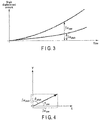
- an angular velocity which cannot be produced by camera shake during normal hand-held photography is set as, for example, a threshold TH.
- the threshold TH is a value for a condition to determine that the follow shot is started when the angular velocity ⁇ that occurs in the camera body 1 exceeds the threshold TH for a predetermined period.
- the angular velocity in the pitch direction to be detected is also deflected from a reference angular velocity in the pitch direction in a tilting operation in which the camera is vertically shaken and thus rotated and moved.
- this state is defined as a zero crossing state. It is detected that the follow shot is finished at a zero crossing time t7. Thus, the period from t2 to t7 is a follow shot detection period B.
- An angular velocity ⁇ pan of panning or an angular velocity ⁇ til of tilting, used for a correction during exposure, is calculated from the angular velocity ⁇ detected in the angle detection period F from the time t3 to the time t5, and from the average value of the angular velocities ⁇ detected in the velocity detection period H from the time t4 to the time t5.
- the camera performs a follow shot in the panning direction.
- An exposure period P extends from the exposure start time t5 to the time t6.
- the exposure start time t5 is the time at which the release switch 9 is pressed.
- the angular velocity ⁇ pan of panning is held, and the difference between the angular velocity ⁇ pan of panning and the angular velocity ⁇ detected by the angular velocity sensor 8 is integrated, so that a blur correction amount G during the panning indicated by the shaded part in FIG. 2 is calculated.
- the area of the shaded part corresponds to the blur correction amount G during the panning.
- ⁇ yaw ⁇ ⁇ yaw / ⁇ ⁇ pitch ⁇ ⁇ pitch
- an angular velocity ⁇ that intersects at right angles with the larger angular velocity is calculated.
- the higher angular velocity is more affected by the moving attributed to the panning operation and is less affected by camera shake. Therefore, on the basis of the higher angular velocity, the angular velocity ⁇ that intersects at right angles is obtained. As a result, the direction in which the camera body 1 is moved is accurately obtained.
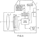
- the optical system 2 forms a subject image, based on an external light flux entering from the direction along the optical axis L, on an imaging plane of the image pickup device 4.
- the focal plane shutter 3 is disposed in front of the image pickup device 4 and opens or closes to bring the image pickup device 4 into an exposure state or a light-shielding state.
- the image pickup device 4 converts the subject image formed on the imaging plane into an electric signal on the basis of an instruction from the system controller 6, and reads this converted electric signal as a video signal.
- the release SW 9 detects each of release operations: a half press (1st release) and a full press (2nd release) which are actions taken by the user to perform a photographic operation, and the release SW 9 outputs detection signals of these release operations to the system controller 6.
- the memory card 12 is a nonvolatile memory to record photographic images.
- the memory card 12 is attachable to and detachable from the camera body 1.
- the drive unit 5 supports the image pickup device 4, and drives the image pickup device 4 to move in the X-axis direction and the Y-axis direction on the basis of an instruction issued from the blur correction microcomputer 7.
- the angular velocity sensor 8 detects, for example, each of the rotational movements in the yaw direction and the pitch direction.
- the angular velocity sensor 8 includes, for example, a yaw angular velocity sensor (first angular velocity detection unit) 8a and a pitch angular velocity sensor (second angular velocity detection unit) 8b that are provided in different mounting directions.
- the pitch angular velocity sensor 8b detects a second angular velocity for rotation in the pitch direction around a direction that intersects at right angles with both the optical axis L and the first axis as a second axis.
- the pitch angular velocity sensor 8b detects an angular change in the pitch direction as the angular velocity ⁇ pitch, and outputs an analog angular velocity detection signal to the blur correction microcomputer 7.
- a roll angular velocity sensor which detects an angular change in the roll direction as the angular velocity ⁇ roll may be provided.
- the blur correction microcomputer 7 calculates blur amounts generated in the imaging plane from the angular velocity detection signals in the yaw direction and the pitch direction output from the angular velocity sensor 8 on the basis of an instruction issued from the system controller 6.
- the blur correction microcomputer 7 issues, to the drive unit 5, a drive instruction to move in a direction to counteract the blur amounts, that is, a drive instruction corresponding to the blur correction amount G shown in FIG. 2 . Therefore, the drive unit 5 drives the image pickup device 4 in a direction to counteract the blur in the imaging plane, so that blurring in the photographic image is prevented.
- the drive unit 5 may drive the optical system 2.
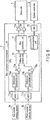
- the two ADCs 71a and 71b respectively convert the analog angular velocity detection signals output from the angular velocity sensor 8 into digital signals.
- the ADC 71a converts the angular velocity detection signal output from the yaw angular velocity sensor 8a into a digital signal.
- the ADC 71b converts the angular velocity detection signal output from the pitch angular velocity sensor 8b into a digital signal.
- Each of the ADCs 71a and 71b converts the analog angular velocity detection signal into a digital signal at intervals of 1 msec, for example, at a sampling rate of 1 kHz.
- the sampling rate is not particularly limited to this rate value, and a higher rate enables more accurate detection.
- the sampling rate has only to be set to an optimum rate in accordance with the performance of a system.
- the CPU 70 executes a program for blur correction amount calculation, acquires each of the angular velocity detection signals in the yaw direction and the pitch direction respectively output from the angular velocity sensors 8a and 8b, calculates each of blur amounts in the yaw direction and the pitch direction generated in the imaging plane of the image pickup device 4, and calculates the blur correction amount G for moving in directions opposite to the blur amounts.
- the program for blur correction amount calculation enables the following functions to be achieved by the CPU 70 of the imaging apparatus including the optical system 2 which images the subject and the image pickup device 4 which outputs an image signal from an optical image formed by the optical system 2: a function to detect the angular velocity ⁇ yaw for rotation in the yaw direction; a function to detect the angular velocity ⁇ pitch for rotation in the pitch direction; a function to judge whether the state is a follow shot state on the basis of the angular velocity ⁇ yaw in the yaw direction and the angular velocity ⁇ pitch in the pitch direction; a function to drive one or both of the optical system 2 and the image pickup device 4 to make a correction for eliminating an image blur caused during the follow shot; a function to calculate a panning angular velocity ⁇ pan in the yaw direction and a tilting angular velocity ⁇ til in the pitch direction associated with the camera operation of the follow shot on the basis of the ratio between the angular velocity ⁇ of strong shaking immediately before
- the reference values (stationary angular velocity reference values) of the angular velocities ⁇ yaw and ⁇ pitch at a stationary time are calculated for the following purposes.
- the output of angular velocity detection detected by the angular velocity sensor at the stationary time is originally zero, but may actually include an offset component of a direct-current component in a sensor output. Therefore, to detect the correct angular velocity, the stationary angular velocity reference values corresponding to the offset component are subtracted from the value of the actually detected angular velocity to perform compensation.
- Both the stationary angular velocity reference values in the yaw direction and the pitch direction can be calculated by taking average values of sufficiently long periods (about several seconds), but are not exclusively found in this manner and may be found by various methods.
- LPF low pass filter
- HPF high pass filter
- Each of the two subtraction units 75a and 75b subtracts each of the reference values respectively calculated by the reference calculation units 74a and 74b from the angular velocity detection signals respectively output from the angular velocity sensors 8a and 8b.
- the subtraction unit 75a subtracts the reference value in the yaw direction calculated by the reference calculation unit 74a from the angular velocity detection signal (angular velocity ⁇ yaw) output from the angular velocity sensor 8a in the yaw direction.
- the subtraction unit 75b subtracts the reference value in the pitch direction calculated by the reference calculation unit 74b from the angular velocity detection signal (angular velocity ⁇ pitch) output from the angular velocity sensor 8b in the pitch direction.
- Each of the reference values is thus subtracted from each of the angular velocities ⁇ yaw and ⁇ pitch so that each of the angular velocities ⁇ yaw and ⁇ pitch will be an angular velocity having a sign (+, -).
- the signs (+, -) can be treated as the rotational directions of the detected angular velocities ⁇ yaw and ⁇ pitch.
- the follow shot control unit 76 determines whether the state is a follow shot state on the basis of the angular velocity ⁇ yaw in the yaw direction detected by the angular velocity sensor 8a and the angular velocity ⁇ pitch in the pitch direction detected by the angular velocity sensor 8b.
- the follow shot control unit 76 loads the subtraction signal in the yaw direction output from the subtraction unit 75a, that is, the angular velocity ⁇ yaw having the sign (+, -) and the subtraction signal in the pitch direction output from the subtraction unit 75b, that is, the angular velocity ⁇ pitch having the sign (+, -), and determines by the angular velocities ⁇ yaw and ⁇ pitch that the follow shot is started.
- the follow shot control unit 76 When it is determined that photography is started during the follow shot, the follow shot control unit 76 outputs each of corrected angular velocities ⁇ stabyaw and ⁇ stabpitch in which the panning angular velocity ⁇ pan and the tilting angular velocity ⁇ til related to the follow shot are respectively removed from the angular velocities ⁇ yaw and ⁇ pitch.
- the blur correction unit 77 integrates each of the corrected angular velocities ⁇ stabyaw and ⁇ stabpitch output from the follow shot control unit 76 to obtain each angular change, and calculates blur amounts generated in the imaging plane of the image pickup device 4 from the angular changes and the focal distance of the optical system 2.
- the blur correction unit 77 then obtains the blur correction amounts G (Gy, Gp) in the yaw direction and the pitch direction to offset the blur amounts, and issues a drive instruction corresponding to the blur correction amounts G (Gy, Gp) to the drive unit 5 the drivers 73a and 73b, respectively.
- There are various methods of calculating the blur correction amounts G (Gy, Gp) thus the blur correction amounts G (Gy, Gp) have only to be calculated by one of the calculation methods.
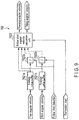
- FIG. 7 shows a specific block configuration diagram of the follow shot control unit 76.
- the follow shot control unit 76 includes two follow shot detection units 761a and 761b, a follow shot angular velocity calculation unit 762, and two subtraction units 763a and 763b.
- the follow shot detection unit 761a inputs the angular velocity ⁇ yaw in the yaw direction having the sign (+, -) output from the subtraction unit 75a, checks whether the angular velocity ⁇ yaw has continuously exceeded the threshold TH for the detection period A on the basis of the angular velocity ⁇ yaw as shown in FIG. 2 , and detects whether the follow shot operation is being performed.
- the follow shot detection unit 761b inputs the angular velocity ⁇ pitch in the pitch direction having the sign (+, -) output from the subtraction unit 75b, checks whether the angular velocity ⁇ pitch has continuously exceeded the threshold TH for the detection period A on the basis of the angular velocity ⁇ pitch as shown in FIG. 2 , and detects whether the follow shot operation is being performed.
- the follow shot angular velocity calculation unit 762 calculates the panning angular velocity ⁇ pan in the yaw direction and the tilting angular velocity ⁇ til in the pitch direction on the basis of the angular velocities ⁇ yaw and ⁇ pitch for a predetermined period immediately before photography.
- the panning angular velocity ⁇ pan and the tilting angular velocity ⁇ til occur due to the follow shot.
- the subtraction unit 763a receives the angular velocity ⁇ yaw in the yaw direction having the sign (+, -) output from the subtraction unit 75a, subtracts the panning angular velocity ⁇ pan calculated by the follow shot angular velocity calculation unit 762 from the angular velocity ⁇ yaw in the yaw direction, and calculate an angular velocity to be corrected, that is, the correction angular velocity ⁇ stabyaw in the yaw direction.
- the subtraction unit 763b receives the angular velocity ⁇ pitch in the pitch direction having the sign (+, -) output from the subtraction unit 75b, subtracts the tilting angular velocity ⁇ til calculated by the follow shot angular velocity calculation unit 762 from the angular velocity ⁇ pitch in the pitch direction, and calculate an angular velocity to be corrected, that is, the correction angular velocity ⁇ stabpitch.
- each of the follow shot detection units 761a and 761b is described with reference to a block configuration diagram shown in FIG. 8 .
- Each of the follow shot detection units 761a and 761b has the same configuration, and includes a moving average calculation unit 7611, a threshold comparison unit 7612, a clocking unit 7613, a zero crossing detection unit 7614, a follow shot detection flag unit 7615, and a limit detection unit 7616.
- the moving average calculation unit 7611 sequentially receives the angular velocities ⁇ yaw in the yaw direction having the sign (+, -) output from the subtraction unit 75a, and calculates a moving average value Ave ⁇ yaw of the angular velocities ⁇ yaw in the yaw direction on the basis of sampling values immediately before each of the angular velocities ⁇ yaw.
- the moving average calculation unit 7611 sequentially receives the angular velocities ⁇ pitch in the pitch direction having the sign (+, -) output from the subtraction unit 75b, and calculates a moving average value Ave ⁇ pitch of the angular velocities ⁇ pitch in the pitch direction on the basis of sampling values immediately before each of the angular velocities ⁇ pitch.
- No moving average calculation unit 7611 may be provided. However, the provision of the moving average calculation unit 7611 enables the follow shot to be stably detected even if noise resulting from various external factors such as an impact during the operation of the shutter is generated.
- the threshold comparison unit 7612 compares the moving average value Ave ⁇ yaw of the angular velocities ⁇ yaw in the yaw direction calculated by the moving average calculation unit 7611 with the threshold TH in the yaw direction, and determines whether the moving average value Ave ⁇ yaw of the angular velocities ⁇ yaw in the yaw direction has exceeded the threshold TH in the yaw direction.
- the threshold comparison unit 7612 compares the moving average value Ave ⁇ pitch of the angular velocities ⁇ pitch in the pitch direction calculated by the moving average calculation unit 7611 with the threshold TH in the pitch direction, and determines whether the moving average value Ave ⁇ pitch of the angular velocities ⁇ pitch in the pitch direction has exceeded the threshold TH in the pitch direction.
- Each of the thresholds TH in the yaw direction and the pitch direction is set to an angular velocity ⁇ of, for example, about 10 deg/s which does not occur in normal hand-held photography.
- This angular velocity ⁇ may be a fixed value or may be changed in accordance with, for example, the focal distance of the optical system 2 and thereby enables detection suited to a photographic field angle.
- the clocking unit 7613 measures the period in which the moving average value Ave ⁇ yaw of the angular velocities ⁇ yaw in the yaw direction or the moving average value Ave ⁇ pitch of the angular velocities ⁇ pitch in the pitch direction is determined to have exceeded each of the thresholds TH in the yaw direction and the pitch direction from the result of the comparison by the threshold comparison unit 7612.
- the clocking unit 7613 determines whether the measured period has exceeded the predetermined detection period A. If the measured period exceeds the detection period A, the clocking unit 7613 detects that the follow shot is started from the point of the excess.
- the zero crossing detection unit 7614 receives the moving average value Ave ⁇ yaw of the angular velocities ⁇ yaw in the yaw direction or the moving average value Ave ⁇ pitch of the angular velocities ⁇ pitch in the pitch direction calculated by the moving average unit 7611, and determines whether the moving average value Ave ⁇ yaw of the angular velocities ⁇ yaw in the yaw direction or the moving average value Ave ⁇ pitch of the angular velocities ⁇ pitch in the pitch direction has crossed zero. The zero crossing is determined by whether the sign (+, -) of the moving average value Ave ⁇ yaw or Ave ⁇ pitch of the angular velocity has been inverted or has become the value "0".
- the follow shot detection flag unit 7615 sets a flag (follow shot flag) at the time of the detection. If the zero crossing is detected by the zero crossing detection unit 7614, the follow shot detection flag unit 7615 clears the follow shot flag at the detection of the zero crossing. That is, the period from the setting of the follow shot flag to its clearance is the follow shot detection period B, and the follow shot operation is performed in this period B.
- the limit detection unit 7616 performs a clocking operation in the follow shot detection period B in which the follow shot flag is set, and clears the follow shot flag if the period clocked by the clocking operation exceeds a preset given period.
- the follow shot angular velocity calculation unit 762 includes two average value buffers 7621a and 7621b, two integration units 7622a and 7622b, and a follow shot angular velocity calculation unit 7623.
- the average value buffer 7621a receives the angular velocities ⁇ yaw in the yaw direction having the sign (+, -) output from the subtraction unit 75a, and holds the average values of the angular velocities ⁇ yaw in a given period.
- the average value buffer 7621a holds, for example, 8 pieces of data regarding 8-period average values every 8 periods from the latest.
- the average value buffer 7621b receives the angular velocities ⁇ pitch in the pitch direction having the sign (+, -) output from the subtraction unit 75b, and holds the average values of the angular velocities ⁇ pitch in a given period.
- Each of the average value buffers 7621a and 7621b holds, but not exclusively, 8 pieces of data regarding 8-period average values every 8 periods from the latest, and may hold other data quantities.
- the integration unit 7622a sequentially acquires and integrates 8 pieces of data regarding the average values calculated and held by the average value buffer 7621a.
- the integration unit 7622b sequentially acquires and integrates 8 pieces of data regarding the average values calculated and held by the average value buffer 7621b.
- Each of the average values Avecoyaw and Ave ⁇ pitch of the angular velocities ⁇ yaw and ⁇ pitch in the yaw direction and the pitch direction is the average value of the latest 8 pieces of data on each of the angular velocities ⁇ yaw and ⁇ pitch.
- the latest 16 pieces of data data of every 8 cycles are used, so that the ratio of the integration values of the angular velocities ⁇ yaw and ⁇ pitch in the yaw direction for a long period can be obtained with a smaller quantity of data.
- the period for obtaining this ratio serves to remove the influence of the camera shake to obtain the ratio between the angular velocity ⁇ yaw in the yaw direction and the angular velocity ⁇ pitch in the pitch direction, and has only to be a period in which the camera shake component can be removed.
- the follow shot angular velocity calculation unit 7623 obtains the ratio between the integration value of the angular velocity ⁇ yaw in the yaw direction calculated by the integration unit 7622a and the integration value of the angular velocity ⁇ pitch in the pitch direction calculated by the integration unit 7622b, and the magnitude correlation of absolute values between the integration value of the angular velocity ⁇ yaw and the integration value of the angular velocity ⁇ pit to calculate a panning angular velocity in the yaw direction and a tilting angular velocity in the pitch direction.
- the integration value of the angular velocity ⁇ yaw in the yaw direction is compared with the integration value of the angular velocity ⁇ pitch in the pitch direction.
- the other angular velocity is calculated.
- the follow shot angular velocity calculation unit 7623 outputs, as the panning angular velocity ⁇ pan in the yaw direction without modification, the latest average value of the angular velocities ⁇ yaw in the yaw direction output from the average value buffer 7621a.
- the follow shot angular velocity calculation unit 7623 calculates the tilting angular velocity ⁇ til in the pitch direction on the basis of the above expression (3) from the latest average value of the angular velocities ⁇ yaw in the yaw direction output from the average value buffer 7621a, the integration value of the angular velocity ⁇ yaw in the yaw direction, and the angular velocity ⁇ pitch in the pitch direction.
- the follow shot angular velocity calculation unit 7623 uses, as the tilting angular velocity ⁇ til in the pitch direction without modification, the latest average value of the angular velocities ⁇ pitch in the pitch direction output from the average value buffer 7621b.
- the follow shot angular velocity calculation unit 7623 calculates the panning angular velocity ⁇ pan in the yaw direction on the basis of the above expression (4) from the latest average value of the angular velocities ⁇ pitch in the pitch direction output from the average value buffer 7621b, the integration value of the angular velocity ⁇ yaw in the yaw direction, and the integration value of the angular velocity ⁇ pitch in the pitch direction.
- FIG. 10 is a flowchart showing the flow of the control of the follow shot control unit.
- step S1 the moving average calculation unit 7611 of the follow shot detection unit 761a sequentially receives the angular velocities ⁇ yaw in the yaw direction having the sign (+, -) output from the subtraction unit 75a, and calculates a moving average value Ave ⁇ yaw of the angular velocities ⁇ yaw in the yaw direction on the basis of sampling values immediately before each of the angular velocities ⁇ yaw.
- the moving average calculation unit 7611 sequentially receives the angular velocities ⁇ pitch in the pitch direction having the sign (+, -) output from the subtraction unit 75b, and calculates a moving average value Ave ⁇ pitch of the angular velocities ⁇ pitch in the pitch direction on the basis of sampling values immediately before each of the angular velocities ⁇ pitch.
- step S2 the zero crossing detection unit 7614 receives the average value Ave ⁇ yaw of the angular velocities ⁇ yaw in the yaw direction calculated by the moving average calculation unit 7611, and determines whether the average value Ave ⁇ yaw of the angular velocities ⁇ yaw in the yaw direction has crossed zero.
- the zero crossing detection unit 7614 also receives the average value Ave ⁇ pitch of the angular velocities ⁇ pitch in the pitch direction calculated by the moving average calculation unit 7611, and determines whether the average value Ave ⁇ pitch of the angular velocities ⁇ pitch in the pitch direction has crossed zero.
- the zero crossing is determined by whether the sign (+, -) of the angular velocity ⁇ yaw or ⁇ pitch has been inverted or has become the value "0".
- the zero crossing is considered to have occurred and a zero crossing flag is set when the sign (+, -) of the previously calculated average value Ave ⁇ yaw of the angular velocities ⁇ yaw in the yaw direction is different from the sign (+, -) of the currently calculated average value Ave ⁇ yaw of the angular velocities ⁇ yaw in the yaw direction or when the currently calculated average value Ave ⁇ yaw of the angular velocities ⁇ yaw in the yaw direction is "0".
- the zero crossing is considered to have occurred and a zero crossing flag is set when the sign (+, -) of the previously calculated average value Ave ⁇ pitch of the angular velocities ⁇ pitch in the pitch direction is different from the sign (+, -) of the currently calculated average value Ave ⁇ pitch of the angular velocities ⁇ pitch in the pitch direction or when the currently calculated average value Ave ⁇ pitch of the angular velocities ⁇ pitch in the pitch direction is "0".
- step S3 the follow shot detection unit 761a receives the angular velocity ⁇ yaw in the yaw direction having the sign (+, -) output from the subtraction unit 75a, and detects on the basis of the angular velocity ⁇ yaw whether the follow shot operation is performed. If the start of the follow shot is detected, the follow shot detection unit 761a sets a follow shot flag.
- the follow shot detection unit 761b inputs the angular velocity ⁇ pitch in the pitch direction having the sign (+, -) output from the subtraction unit 75b, and detects on the basis of the angular velocity ⁇ pitch whether the follow shot operation is performed. If the start of the follow shot is detected, the follow shot detection unit 761b sets a follow shot flag.
- each of the follow shot detection units 761a and 761b clears the follow shot flag if there is any cause for clearing the follow shot flag.
- the cause for clearing the follow shot flag is the setting of the zero crossing flag or the continuous setting of the follow shot flag for a predetermined time or more.
- the predetermined time is, for example, 10 seconds, and is set to a time longer than the time in which the follow shot is normally continued.
- step S5 the predetermined number of average values of the angular velocities ⁇ yaw in the yaw direction calculated by the average value buffer 7621a of the follow shot angular velocity calculation unit 762 and the predetermined number of average values of the angular velocities ⁇ pitch in the pitch direction calculated by the average value buffer 7621b are held in, for example, buffer memories included in the average value buffers 7621a and 7621b every predetermined period. For example, 8 pieces of data regarding average values in every 8 periods are held here.
- step S6 the follow shot detection units 761a and 761b determines whether or not the follow shot flag is set, and determines whether or not the period is the follow shot detection period B shown in FIG. 2 .
- step S7 If it is determined that the period is the follow shot detection period B, the procedure moves to step S7, and then whether or not the state of the present apparatus (camera) is the exposure state is determined. If the period is not the follow shot detection period B, the procedure moves to step S11, and the panning angular velocity ⁇ pan in the pitch direction and the tilting angular velocity ⁇ til in the yaw direction are each cleared to "0".
- step S8 determines in step S8 whether the present apparatus (camera) is performing the first correction processing after the start of correction or is performing a correction.
- the system controller 6 causes each of the integration units 7622a and 7622b to perform an integral operation in step S9.
- the integration unit 7622a integrates 8 pieces of data regarding the average values held by the average value buffer 7621a.
- the integration unit 7622b integrates 8 pieces of data regarding the average values held by the average value buffer 7621b.
- the follow shot angular velocity calculation unit 7623 obtains the ratio between the integration value of the angular velocity ⁇ yaw in the yaw direction calculated by the integration unit 7622a and the integration value of the angular velocity ⁇ pitch in the pitch direction calculated by the integration unit 7622b, and the magnitude correlation of absolute values between the integration value of the angular velocity ⁇ yaw and the integration value of the angular velocity ⁇ pit.
- the follow shot angular velocity calculation unit 7623 then calculates the panning angular velocity ⁇ pan in the yaw direction and the follow shot angular velocity ⁇ pitch in the pitch direction which are angular velocities associated with the follow shots in the yaw direction and the pitch direction.
- step S12 the subtraction unit 763a receives the angular velocity ⁇ yaw in the yaw direction having the sign (+, -) output from the subtraction unit 75a, subtracts the panning angular velocity ⁇ pan in the yaw direction calculated by the follow shot angular velocity calculation unit 762 from the angular velocity ⁇ yaw in the yaw direction, and calculates a yaw correction angular velocity to be corrected.
- step S12 the subtraction unit 763b receives the angular velocity ⁇ pitch in the pitch direction having the sign (+, -) output from the subtraction unit 75b, subtracts the tilting angular velocity ⁇ til in the pitch direction calculated by the follow shot angular velocity calculation unit 762 from the angular velocity ⁇ pitch in the pitch direction, and calculates a pitch correction angular velocity to be corrected.
- the blur correction unit 77 integrates the yaw correction angular velocity and pitch correction angular velocity to calculate correction amounts, and performs corrected driving of the drive unit 5 in accordance with the correction amounts so that the blur amounts associated with the camera shake other than the angular velocity associated with the follow shot are only corrected.
- both the panning angular velocity ⁇ pan and the tilting angular velocity ⁇ til are 0, so that the system controller 6 functions for normal camera shake correction.
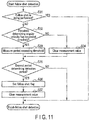
- step S3 the specific operation of the follow shot detection processing (step S3) is described with reference to a block configuration diagram of the follow shot detection unit shown in FIG. 8 and a follow shot detection processing control flowchart shown in FIG. 11 .
- each of the follow shot detection units 761a and 761b determines whether or not the follow shot flag is set, and thereby determines whether the follow shot is being performed.
- the follow shot flag is set by the follow shot detection flag unit 7615. If it is determined that the follow shot is already started and the follow shot flag is set, the follow shot detection units 761a and 761b bypass the present follow shot detection processing.
- the threshold comparison unit 7612 compares the average value of the angular velocities ⁇ yaw in the yaw direction calculated by the moving average calculation unit 7611 with the threshold TH in the yaw direction as shown in FIG. 2 , and determines whether the average value Ave ⁇ yaw of the angular velocities ⁇ yaw in the yaw direction has exceeded the threshold TH in the yaw direction, in step S32.
- the clocking unit 7613 counts up a counter for measuring the determined periods t1 to t2 when it is determined in step S33 that the average value Ave ⁇ yaw of the angular velocities ⁇ yaw in the yaw direction and the average value Ave ⁇ pitch of the angular velocities ⁇ pitch in the pitch direction have respectively exceeded the thresholds TH in the yaw direction and the pitch direction.
- the clocking unit 7613 counts up the counter and then measures the detection period A shown in FIG. 2 .
- the clocking unit 7613 clears the measurement value in the counter in each of the corresponding directions to "0" in step S34.
- step S35 the clocking unit 7613 determines whether the measurement period t1 to t2 in which the counter is counted up has exceeded the predetermined detection period A.
- the follow shot detection flag unit 7615 sets the follow shot flag at the time t2 when the measurement period has exceeded the predetermined detection period A, in step S36.
- step S37 the limit detection unit 7616 clears the follow shot detection flag at the point where the period clocked by the clocking operation in the clocking unit 7613 has exceeded the preset detection period. If the zero crossing is detected by the zero crossing detection unit 7614, the limit detection unit 7616 clears the follow shot flag at the zero crossing detection time t7. As a result, the period from the time t2 at which the follow shot flag is set to the time t7 at which the follow shot flag is cleared is the follow shot detection period B. The follow shot operation is being performed in the follow shot detection period B.
- step S10 The specific operation of the follow shot angular velocity calculation processing (step S10) is described with reference to a block configuration diagram of the follow shot angular velocity calculation unit 762 shown in FIG. 9 and a flowchart of the control regarding the follow shot angular velocity calculation shown in FIG. 12 .
- the follow shot angular velocity calculation unit 7623 receives an integration value ⁇ Ave_ ⁇ yaw by the integration unit 7622a and an integration value ⁇ Ave_ ⁇ pitch by the integration unit 7622b that are calculated at the first period to start a blur correction.
- step S91 the follow shot angular velocity calculation unit 7623 obtains each of absolute values
- the follow shot angular velocity calculation unit 7623 determines that the camera body 1 is preferentially shaken in the yaw direction to perform the follow shot, and determines the average value Ave ⁇ yaw of the angular velocities ⁇ yaw in the yaw direction as the panning angular velocity ⁇ pan in the yaw direction in step S92.
- step S93 the follow shot angular velocity calculation unit 7623 calculates the tilting angular velocity ⁇ til in the pitch direction on the basis of the average value Ave ⁇ yaw of the angular velocities ⁇ yaw in the yaw direction and the angular velocity ⁇ pitch in the pitch direction shown in the above expression (3). That is, the follow shot angular velocity calculation unit 7623 calculates the following expression (6) to figure out the tilting angular velocity ⁇ til in the pitch direction.
- ⁇ til Ave ⁇ yaw ⁇ ⁇ Ave _ ⁇ pitch / ⁇ Ave _ ⁇ yaw
- the follow shot angular velocity calculation unit 7623 determines that the camera body 1 is preferentially shaken in the pitch direction to perform the follow shot, and determines the average value Ave ⁇ pitch of the angular velocities ⁇ pitch in the pitch direction as the tilting angular velocity ⁇ til in the pitch direction in step S94.
- step S95 the follow shot angular velocity calculation unit 7623 calculates the panning angular velocity ⁇ pan in the yaw direction on the basis of the average value Ave ⁇ pitch of the angular velocities ⁇ pitch in the pitch direction and the angular velocity ⁇ yaw in the yaw direction shown in the above expression (4). That is, the follow shot angular velocity calculation unit 7623 calculates the following expression (7) to figure out the reference angular velocity ⁇ pan in the yaw direction.
- ⁇ pan Ave ⁇ pitch ⁇ ⁇ Ave _ ⁇ yaw / ⁇ Ave _ ⁇ pitch
- the subtraction unit 763a then subtracts the angular velocity ⁇ yaw in the yaw direction output from the subtraction unit 75a and the panning angular velocity ⁇ pan in the yaw direction calculated in the above manner, and calculates an angular velocity to be corrected, that is, a yaw correction angular velocity.
- the subtraction unit 763b then subtracts the angular velocity ⁇ pitch in the pitch direction output from the subtraction unit 75b and the tilting angular velocity ⁇ til in the pitch direction calculated in the above manner, and calculates an angular velocity to be corrected, that is, a pitch correction angular velocity.
- the blur correction unit 77 integrates the yaw correction angular velocity and the pitch correction angular velocity output from the follow shot control unit 76, and calculates blur amounts generated in the imaging plane of the image pickup device 4 from the angular changes and the focal distance of the optical system 2.
- the blur correction unit 77 obtains each of the blur correction amounts G (Gy, Gp) in the yaw direction and the pitch direction to offset the blur amounts, and issues a drive instruction corresponding to the blur correction amounts G (Gy, Gp) to the drive unit 5 the drivers 73a and 73b, respectively.
- the drive unit 5 drives the image pickup device 4 to move in the X-axis direction and the Y-axis direction on the basis of the drive instruction corresponding to each of the blur correction amounts G (Gy, Gp) in the yaw direction and the pitch direction, so that the blur generated in the imaging plane of the image pickup device 4 is corrected.
- the panning angular velocity ⁇ pan of the angular velocity ⁇ yaw in the yaw direction is calculated on the basis of the output signal from the angular velocity sensor 8a, the panning angular velocity ⁇ pan in the yaw direction and the angular velocity ⁇ yaw in the yaw direction are subtracted, and the blur correction amount G (Gy) in the yaw direction is calculated.
- the tilting angular velocity ⁇ til of the angular velocity ⁇ pitch in the pitch direction is calculated on the basis of the output signal from the angular velocity sensor 8b, the tilting angular velocity ⁇ til in the pitch direction and the angular velocity ⁇ pitch in the pitch direction are subtracted, and the blur correction amount G (Gp) in the pitch direction is calculated.
- the drive instructions corresponding to the blur correction amounts G (Gy, Gp) in the yaw direction and the pitch direction are issued to drive the image pickup device 4 to move in the X-axis direction and the Y-axis direction.
- the integration value ⁇ Ave_ ⁇ yaw of the average value of the angular velocities ⁇ yaw in the yaw direction and the integration value ⁇ Ave_ ⁇ pitch of the average value of the angular velocities ⁇ pitch in the pitch direction are obtained, and which of the absolute values
- the panning angular velocity ⁇ pan in the yaw direction is determined as the average value Ave ⁇ yaw of the angular velocities ⁇ yaw in the yaw direction, and the above expression (6) is calculated to figure out the tilting angular velocity ⁇ til in the pitch direction.
- the tilting angular velocity ⁇ til in the pitch direction is determined as the average value of the angular velocities ⁇ pitch in the pitch direction, and the above expression (7) is calculated to figure out the reference angular velocity in the yaw direction.
- the panning angular velocity ⁇ pan and the tilting angular velocity ⁇ til in the yaw direction and the pitch direction are calculated on the basis of the angular velocities ⁇ immediately before photography, and during the exposure period P, the movement amount of the subject generated in the imaging plane of the image pickup device 4 is corrected so that the movement amount may be a movement amount based on the panning angular velocity ⁇ pan and the tilting angular velocity ⁇ til in the yaw direction and the pitch direction.
- the variation of the moving velocity of the camera body 1 has no influence, and a blur in a direction that intersects at right angles with the shaking direction of the camera body 1 can be corrected even if the detection direction of the angular velocity ⁇ and the moving direction of the camera body 1 are inclined, so that the probability of a successful follow shot can be improved.
- the moving velocity of the camera is not constant during follow shot photography in an imaging apparatus such as a camera
- a constant movement amount of the subject image generated on the imaging plane of the image pickup device 4 can be maintained.
- the moving direction of the camera is inclined relative to either the pitch direction or the yaw direction, that is, even when the camera is moved in a two-dimensional direction, a blur in a direction that intersects at right angles with the shaking direction can be lessened, the success rate of a follow shot is improved, and the degree of technical difficulty of the follow shot can be reduced.
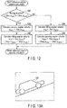
- FIG. 13A to FIG. 13E show how the camera body 1 is moved to follow a subject 100 which moves in parallel.
- FIG. 13A and FIG. 13B show sequential frame images of a live-view displayed on the EVF 11 when the camera body 1 is moved to follow the subject.
- the live-view is displayed on the EVF 11 after the following: the focal plane shutter 3 is opened while the camera is waiting for photography, and an image obtained by the photoelectric conversion of the subject image formed on the image pickup device 4 is read by the system controller 6 in real time and subjected to image processing.
- FIG. 13C shows the movement of the subject 100 between frames.
- Vectors ⁇ x and ⁇ y are detected from the movement amount between frames.
- the vector ⁇ X indicates a movement amount in the X-axis direction on the imaging plane of the image pickup device 4.
- the vector ⁇ y indicates a movement amount in the Y-axis direction on the imaging plane of the image pickup device 4.
- the angle ⁇ yaw in the yaw direction and the angle ⁇ pitch in the pitch direction are angular changes between frames detected by the angular velocity sensor 8 (the yaw angular velocity sensor 8a and the pitch angular velocity sensor 8b). How the camera body 1 is moved in the direction of the angle ⁇ pan is shown by the angle ⁇ yaw in the yaw direction and the angle ⁇ pitch in the pitch direction.
- FIG. 13D shows the camera body 1 seen from the rear surface when the subject 100, for example, a vehicle which moves in parallel shown in FIG. 13A and FIG. 13B is imaged.
- the panning operation is performed while the camera body 1 is inclined in the detection direction of the angular velocity ⁇ .
- FIG. 13E shows a schematic diagram in which the movement direction of the subject 100 is converted into a horizontal direction when the panning operation is performed while the camera body 1 is inclined in the detection direction of the angular velocity ⁇ as shown in FIG. 13A .
- a vector ⁇ target shown in FIG. 13E is a value obtained by converting the movement direction of the subject 100 and the velocity of the subject 100 into an angular change of the camera body 1.
- a movement amount of the blur of the image of the subject 100 appears in the image photographed by the image pickup device 4 when the moving velocity of the camera body 1 does not correspond to the velocity of the subject 100 as shown in FIG. 13C .
- a focal distance f during photography can be converted into an angular change by the following expressions (8) and (9) on the basis of a movement amount ⁇ D of the blur of the image of the subject 100.
- T is a time period determined by a frame rate
- Angular velocities ⁇ x and ⁇ y that have been converted into the yaw direction and the pitch direction can be obtained by the calculation of the angular velocity ⁇ c.
- Each of the difference between the calculated angular velocity ⁇ x and the detected angular velocity ⁇ yaw and the difference between the calculated angular velocity ⁇ y and the detected angular velocity ⁇ pitch is obtained to correct the panning angular velocity ⁇ pan and the tilting angular velocity ⁇ til so that the moving velocity of the camera body 1 can be adjusted to the moving velocity of the subject 100.
- deviations from the panning angular velocity ⁇ pan and the tilting angular velocity ⁇ til are corrected, so that the deviation of the subject image on the imaging plane of the image pickup device 4 can be eliminated.
- FIG. 5 to FIG. 9 are used, and the same parts as those in the first embodiment described above are provided with the same reference signs and are thus not described in detail. The differences are described.
- the system controller 6 detects the subject 100 in the vicinity of the center of the photographic field angle, and calculates an inter-frame movement amount of the subject 100, during the display of the live-view. There have already been various methods of calculating the movement amount, and any one of the calculation methods may be used.
- the system controller 6 calculates movement amounts of the subject 100 in the X-axis direction and the Y-axis direction relative to the imaging plane of the image pickup device 4, and reports each of the movement amounts in the X-axis direction and the Y-axis direction to the blur correction microcomputer 7 by serial communication frame by frame.
- the blur correction microcomputer 7 receives each of the movement amounts in the X-axis direction and the Y-axis direction by the communication unit 78 via the SIO 72.
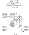
- FIG. 14 shows a specific block configuration diagram of the follow shot control unit 76.
- Two angle conversion units 764a and 764b and two subtraction units 763c and 763d are added to the follow shot control unit 76 as compared to the follow shot control unit 76 according to the first embodiment described above.
- the angle conversion unit 764a calculates the above expressions (9) and (10) on the basis of the movement amount in the X-axis direction to figure out the angular velocity ⁇ x converted into the yaw direction.
- the angle conversion unit 764b calculates the above expressions (9) and (10) on the basis of the movement amount in the Y-axis direction to figure out the angular velocity ⁇ y converted into the pitch direction.
- the subtraction unit 763c subtracts the angular velocity ⁇ x converted into the yaw direction from the panning angular velocity ⁇ pan in the yaw direction calculated by the offset detection unit 762.
- the subtraction unit 763d subtracts the angular velocity ⁇ y converted into the pitch direction from the tilting angular velocity ⁇ til in the pitch direction calculated by the offset detection unit 762.
- FIG. 15 shows a reference angular velocity calculation start flowchart.
- step S90 the angle conversion unit 764a calculates the above expressions (6) and (7) on the basis of the movement amount in the X-axis direction to figure out the angular velocity ⁇ x converted into the yaw direction.
- the angle conversion unit 764b calculates the above expressions (6) and (7) on the basis of the movement amount in the Y-axis direction to figure out the angular velocity ⁇ y converted into the pitch direction.
- the live-view frame rate is 60 fps, so that the calculated angular change is multiplied by 60 which forms the above rate of 60 fps, leading to the angular velocity ⁇ y.
- ⁇ y atan ⁇ X / f ⁇ 60
- step S93 the follow shot angular velocity calculation unit 7623 then calculates the tilting angular velocity ⁇ til in the pitch direction on the basis of the average value of the angular velocities ⁇ yaw in the yaw direction, the angular velocity ⁇ pitch in the pitch direction shown in the above expression (3), and the angular velocity ⁇ y. That is, the follow shot angular velocity calculation unit 7623 calculates the following expression (13) to figure out the reference angular velocity ⁇ til in the pitch direction.
- ⁇ til Ave ⁇ yaw ⁇ ⁇ Ave _ ⁇ pitch / ⁇ Ave _ ⁇ yaw ⁇ ⁇ y
- the angular velocity ⁇ x converted into the yaw direction is calculated on the basis of the movement amount in the X-axis direction
- the angular velocity ⁇ y converted into the pitch direction is calculated on the basis of the movement amount in the Y-axis direction.
- the panning angular velocity and the tilting angular velocity are corrected by the converted angular velocities ⁇ x and ⁇ y. Therefore, in addition to the advantageous effects according to the first embodiment described above, the subject image can be held from moving on the imaging plane of the image pickup device 4 even if the velocity of moving the camera body 1 is not the same as the movement of the subject. Consequently, the panning angular velocity and the tilting angular velocity can be the same as the subject velocity.
- FIG. 5 to FIG. 9 are used, and the same parts as those in the first embodiment described above are provided with the same reference signs and are thus not described in detail. The differences are described.
- FIG. 16 shows a follow shot control start flowchart.
- the difference between this follow shot control start flowchart and the above-described follow shot control start flowchart shown in FIG. 10 is the step position to perform the follow shot angular velocity calculation (step S10).
Landscapes
- Engineering & Computer Science (AREA)
- Multimedia (AREA)
- Signal Processing (AREA)
- Physics & Mathematics (AREA)
- General Physics & Mathematics (AREA)
- Adjustment Of Camera Lenses (AREA)
- Studio Devices (AREA)
Applications Claiming Priority (2)
| Application Number | Priority Date | Filing Date | Title |
|---|---|---|---|
| JP2013087689A JP6045430B2 (ja) | 2013-04-18 | 2013-04-18 | 撮像装置及びその像ブレ補正方法 |
| PCT/JP2014/057392 WO2014171251A1 (ja) | 2013-04-18 | 2014-03-18 | 撮像装置及び像ブレ補正方法 |
Publications (3)
| Publication Number | Publication Date |
|---|---|
| EP2988169A1 EP2988169A1 (en) | 2016-02-24 |
| EP2988169A4 EP2988169A4 (en) | 2016-09-28 |
| EP2988169B1 true EP2988169B1 (en) | 2018-01-17 |
Family
ID=51731208
Family Applications (1)
| Application Number | Title | Priority Date | Filing Date |
|---|---|---|---|
| EP14785892.2A Not-in-force EP2988169B1 (en) | 2013-04-18 | 2014-03-18 | Imaging device and image shake correction method |
Country Status (5)
| Country | Link |
|---|---|
| US (1) | US9525822B2 (enExample) |
| EP (1) | EP2988169B1 (enExample) |
| JP (1) | JP6045430B2 (enExample) |
| CN (1) | CN105122131B (enExample) |
| WO (1) | WO2014171251A1 (enExample) |
Families Citing this family (21)
| Publication number | Priority date | Publication date | Assignee | Title |
|---|---|---|---|---|
| JP6486087B2 (ja) * | 2014-12-03 | 2019-03-20 | キヤノン株式会社 | 像ブレ補正装置、撮像装置および制御方法 |
| US9900513B2 (en) * | 2015-01-16 | 2018-02-20 | Canon Kabushiki Kaisha | Control apparatus, optical apparatus, and lens apparatus |
| JP6613619B2 (ja) * | 2015-05-20 | 2019-12-04 | リコーイメージング株式会社 | 撮像装置および撮像装置の制御方法 |
| JP6525724B2 (ja) * | 2015-05-20 | 2019-06-05 | キヤノン株式会社 | パンニング情報表示装置、パンニング情報の表示処理を実行する方法およびパンニング情報表示プログラム |
| JP6598537B2 (ja) * | 2015-07-01 | 2019-10-30 | キヤノン株式会社 | 画像処理装置、撮像装置および画像処理プログラム |
| FR3041136A1 (fr) * | 2015-09-14 | 2017-03-17 | Parrot | Procede de determination d'une duree d'exposition d'une camera embarque sur un drone, et drone associe. |
| JP6596745B2 (ja) | 2015-10-20 | 2019-10-30 | エスゼット ディージェイアイ テクノロジー カンパニー リミテッド | 対象物体を撮像するシステム |
| JP6592335B2 (ja) | 2015-11-05 | 2019-10-16 | キヤノン株式会社 | 像ブレ補正装置及び方法 |
| JP6600232B2 (ja) | 2015-11-05 | 2019-10-30 | キヤノン株式会社 | 像ブレ補正装置及び方法 |
| JP2017116840A (ja) * | 2015-12-25 | 2017-06-29 | オリンパス株式会社 | 撮像装置 |
| JP6655401B2 (ja) * | 2016-01-21 | 2020-02-26 | オリンパス株式会社 | 撮像装置、像ブレ補正方法 |
| JP6700874B2 (ja) * | 2016-03-08 | 2020-05-27 | キヤノン株式会社 | 像ブレ補正装置及びその制御方法、プログラム、記憶媒体 |
| EP3460568B1 (en) * | 2016-05-16 | 2021-09-15 | Sony Group Corporation | Imaging device and image blur correction method |
| JP6821358B2 (ja) * | 2016-08-31 | 2021-01-27 | キヤノン株式会社 | 制御装置、撮像装置、レンズ装置、制御方法、プログラム、および、記憶媒体 |
| JP6873716B2 (ja) * | 2017-01-31 | 2021-05-19 | キヤノン株式会社 | 像ブレ補正装置およびその制御方法、撮像装置、レンズ装置 |
| JP2018146663A (ja) * | 2017-03-02 | 2018-09-20 | キヤノン株式会社 | 像ブレ補正装置およびその制御方法、撮像装置、レンズ装置 |
| US11232581B2 (en) * | 2017-08-02 | 2022-01-25 | Sony Group Corporation | Information processing apparatus, information processing method, and recording medium |
| US10740431B2 (en) * | 2017-11-13 | 2020-08-11 | Samsung Electronics Co., Ltd | Apparatus and method of five dimensional (5D) video stabilization with camera and gyroscope fusion |
| JP7086591B2 (ja) * | 2017-12-20 | 2022-06-20 | キヤノン株式会社 | 撮像装置およびその制御方法 |
| CN114339051B (zh) * | 2021-12-30 | 2025-07-25 | 维沃移动通信有限公司 | 拍摄方法、装置、电子设备和可读存储介质 |
| JP2023180547A (ja) * | 2022-06-09 | 2023-12-21 | キヤノン株式会社 | 撮像装置およびその制御方法 |
Family Cites Families (13)
| Publication number | Priority date | Publication date | Assignee | Title |
|---|---|---|---|---|
| EP0556666B1 (en) * | 1992-02-06 | 1999-04-28 | Nikon Corporation | Camera with pan shot detecting device |
| JPH05216104A (ja) | 1992-02-06 | 1993-08-27 | Nikon Corp | 流し撮り装置 |
| JP3899584B2 (ja) * | 1997-04-02 | 2007-03-28 | ソニー株式会社 | 画像振れ補正装置および方法 |
| JP3466895B2 (ja) * | 1997-12-12 | 2003-11-17 | キヤノン株式会社 | 振れ補正装置、撮像装置、撮像システム、カメラユニット、及びレンズユニット |
| JP2006171654A (ja) * | 2004-12-20 | 2006-06-29 | Olympus Corp | 撮影装置 |
| JP4438099B2 (ja) * | 2007-11-22 | 2010-03-24 | カシオ計算機株式会社 | 撮像装置及びそのプログラム |
| JP5439734B2 (ja) * | 2008-03-31 | 2014-03-12 | リコーイメージング株式会社 | 撮像装置 |
| JP5111306B2 (ja) * | 2008-08-29 | 2013-01-09 | キヤノン株式会社 | 像ブレ補正機能を有する光学機器及びその制御方法 |
| JP5268546B2 (ja) * | 2008-10-06 | 2013-08-21 | キヤノン株式会社 | 光学機器及びその制御方法 |
| JP2011137996A (ja) * | 2009-12-28 | 2011-07-14 | Canon Inc | レンズ装置 |
| JP5600516B2 (ja) * | 2010-08-09 | 2014-10-01 | キヤノン株式会社 | 撮像装置 |
| JP2012058545A (ja) * | 2010-09-09 | 2012-03-22 | Canon Inc | 撮像装置 |
| JP2012163852A (ja) * | 2011-02-08 | 2012-08-30 | Nikon Corp | ブレ補正装置及び光学機器 |
-
2013
- 2013-04-18 JP JP2013087689A patent/JP6045430B2/ja active Active
-
2014
- 2014-03-18 WO PCT/JP2014/057392 patent/WO2014171251A1/ja not_active Ceased
- 2014-03-18 CN CN201480021733.1A patent/CN105122131B/zh not_active Expired - Fee Related
- 2014-03-18 EP EP14785892.2A patent/EP2988169B1/en not_active Not-in-force
-
2015
- 2015-10-02 US US14/874,239 patent/US9525822B2/en not_active Expired - Fee Related
Non-Patent Citations (1)
| Title |
|---|
| None * |
Also Published As
| Publication number | Publication date |
|---|---|
| WO2014171251A1 (ja) | 2014-10-23 |
| JP6045430B2 (ja) | 2016-12-14 |
| EP2988169A1 (en) | 2016-02-24 |
| CN105122131B (zh) | 2018-04-20 |
| EP2988169A4 (en) | 2016-09-28 |
| JP2014211531A (ja) | 2014-11-13 |
| US20160028958A1 (en) | 2016-01-28 |
| CN105122131A (zh) | 2015-12-02 |
| US9525822B2 (en) | 2016-12-20 |
Similar Documents
| Publication | Publication Date | Title |
|---|---|---|
| EP2988169B1 (en) | Imaging device and image shake correction method | |
| US9131156B2 (en) | Amount-of-shake sensing apparatus, imaging apparatus, and method for detecting the amount of shake | |
| EP2360638B1 (en) | Method, system and computer program product for obtaining a point spread function using motion information | |
| US9525820B2 (en) | Shake amount detection device and imaging device | |
| JP5572031B2 (ja) | 撮像装置及びその制御方法 | |
| US20080252736A1 (en) | Image stabilization method and apparatus | |
| US8964046B2 (en) | Amount-of-shake sensing apparatus, imaging apparatus, and method of detecting the amount of shake | |
| US11431907B2 (en) | Imaging device capable of correcting image blur of a captured image and control method therefor | |
| JP2013148717A (ja) | ブレ量検出装置、撮像装置、ブレ量検出方法 | |
| CN109391755A (zh) | 摄像设备及其中执行的方法 | |
| JP6525724B2 (ja) | パンニング情報表示装置、パンニング情報の表示処理を実行する方法およびパンニング情報表示プログラム | |
| JP2012128356A (ja) | ブレ補正装置及び光学機器 | |
| CN111953891B (zh) | 控制设备、镜头设备、摄像设备、控制方法和存储介质 | |
| JP6024031B2 (ja) | ブレ補正装置及び光学機器 | |
| JP2005318568A (ja) | 画像補正装置、および画像補正方法 | |
| CN116437207A (zh) | 光学防抖方法和装置、电子设备、计算机可读存储介质 | |
| CN113497893A (zh) | 摄像装置和摄像装置的控制方法 | |
| JP2023062881A (ja) | 撮像装置およびその制御方法 | |
| US20200120280A1 (en) | Image blur correction device, control method thereof, and imaging apparatus | |
| WO2016157666A1 (ja) | カメラ姿勢推定装置、運転支援装置、及び、カメラ姿勢推定方法 | |
| JP5959315B2 (ja) | ブレ量検出装置、撮像装置、ブレ量検出方法 | |
| US20230417575A1 (en) | Orientation calculation apparatus, orientation calculation method, imaging apparatus including orientation calculation apparatus, and method for controlling same | |
| CN104704804A (zh) | 摄像装置、检测装置 | |
| KR20260058380A (ko) | 영상의 흔들림을 보정하는 영상 처리 장치 및 그 흔들림 보정 방법 | |
| JP2013250414A (ja) | ブレ補正装置および光学機器 |
Legal Events
| Date | Code | Title | Description |
|---|---|---|---|
| PUAI | Public reference made under article 153(3) epc to a published international application that has entered the european phase |
Free format text: ORIGINAL CODE: 0009012 |
|
| 17P | Request for examination filed |
Effective date: 20151029 |
|
| AK | Designated contracting states |
Kind code of ref document: A1 Designated state(s): AL AT BE BG CH CY CZ DE DK EE ES FI FR GB GR HR HU IE IS IT LI LT LU LV MC MK MT NL NO PL PT RO RS SE SI SK SM TR |
|
| AX | Request for extension of the european patent |
Extension state: BA ME |
|
| DAX | Request for extension of the european patent (deleted) | ||
| A4 | Supplementary search report drawn up and despatched |
Effective date: 20160826 |
|
| RIC1 | Information provided on ipc code assigned before grant |
Ipc: H04N 5/232 20060101ALI20160822BHEP Ipc: G03B 5/00 20060101AFI20160822BHEP |
|
| RAP1 | Party data changed (applicant data changed or rights of an application transferred) |
Owner name: OLYMPUS CORPORATION |
|
| RIN1 | Information on inventor provided before grant (corrected) |
Inventor name: TSUCHIYA, HITOSHI Inventor name: OSANAI, YOJI |
|
| GRAP | Despatch of communication of intention to grant a patent |
Free format text: ORIGINAL CODE: EPIDOSNIGR1 |
|
| STAA | Information on the status of an ep patent application or granted ep patent |
Free format text: STATUS: GRANT OF PATENT IS INTENDED |
|
| INTG | Intention to grant announced |
Effective date: 20170814 |
|
| GRAS | Grant fee paid |
Free format text: ORIGINAL CODE: EPIDOSNIGR3 |
|
| GRAA | (expected) grant |
Free format text: ORIGINAL CODE: 0009210 |
|
| STAA | Information on the status of an ep patent application or granted ep patent |
Free format text: STATUS: THE PATENT HAS BEEN GRANTED |
|
| AK | Designated contracting states |
Kind code of ref document: B1 Designated state(s): AL AT BE BG CH CY CZ DE DK EE ES FI FR GB GR HR HU IE IS IT LI LT LU LV MC MK MT NL NO PL PT RO RS SE SI SK SM TR |
|
| REG | Reference to a national code |
Ref country code: GB Ref legal event code: FG4D |
|
| REG | Reference to a national code |
Ref country code: CH Ref legal event code: EP |
|
| REG | Reference to a national code |
Ref country code: IE Ref legal event code: FG4D |
|
| REG | Reference to a national code |
Ref country code: DE Ref legal event code: R096 Ref document number: 602014020132 Country of ref document: DE Ref country code: AT Ref legal event code: REF Ref document number: 964808 Country of ref document: AT Kind code of ref document: T Effective date: 20180215 |
|
| REG | Reference to a national code |
Ref country code: FR Ref legal event code: PLFP Year of fee payment: 5 |
|
| REG | Reference to a national code |
Ref country code: NL Ref legal event code: MP Effective date: 20180117 |
|
| REG | Reference to a national code |
Ref country code: LT Ref legal event code: MG4D |
|
| REG | Reference to a national code |
Ref country code: AT Ref legal event code: MK05 Ref document number: 964808 Country of ref document: AT Kind code of ref document: T Effective date: 20180117 |
|
| PG25 | Lapsed in a contracting state [announced via postgrant information from national office to epo] |
Ref country code: NL Free format text: LAPSE BECAUSE OF FAILURE TO SUBMIT A TRANSLATION OF THE DESCRIPTION OR TO PAY THE FEE WITHIN THE PRESCRIBED TIME-LIMIT Effective date: 20180117 |
|
| PG25 | Lapsed in a contracting state [announced via postgrant information from national office to epo] |
Ref country code: FI Free format text: LAPSE BECAUSE OF FAILURE TO SUBMIT A TRANSLATION OF THE DESCRIPTION OR TO PAY THE FEE WITHIN THE PRESCRIBED TIME-LIMIT Effective date: 20180117 Ref country code: NO Free format text: LAPSE BECAUSE OF FAILURE TO SUBMIT A TRANSLATION OF THE DESCRIPTION OR TO PAY THE FEE WITHIN THE PRESCRIBED TIME-LIMIT Effective date: 20180417 Ref country code: ES Free format text: LAPSE BECAUSE OF FAILURE TO SUBMIT A TRANSLATION OF THE DESCRIPTION OR TO PAY THE FEE WITHIN THE PRESCRIBED TIME-LIMIT Effective date: 20180117 Ref country code: LT Free format text: LAPSE BECAUSE OF FAILURE TO SUBMIT A TRANSLATION OF THE DESCRIPTION OR TO PAY THE FEE WITHIN THE PRESCRIBED TIME-LIMIT Effective date: 20180117 Ref country code: HR Free format text: LAPSE BECAUSE OF FAILURE TO SUBMIT A TRANSLATION OF THE DESCRIPTION OR TO PAY THE FEE WITHIN THE PRESCRIBED TIME-LIMIT Effective date: 20180117 Ref country code: CY Free format text: LAPSE BECAUSE OF FAILURE TO SUBMIT A TRANSLATION OF THE DESCRIPTION OR TO PAY THE FEE WITHIN THE PRESCRIBED TIME-LIMIT Effective date: 20180117 |
|
| PG25 | Lapsed in a contracting state [announced via postgrant information from national office to epo] |
Ref country code: BG Free format text: LAPSE BECAUSE OF FAILURE TO SUBMIT A TRANSLATION OF THE DESCRIPTION OR TO PAY THE FEE WITHIN THE PRESCRIBED TIME-LIMIT Effective date: 20180417 Ref country code: GR Free format text: LAPSE BECAUSE OF FAILURE TO SUBMIT A TRANSLATION OF THE DESCRIPTION OR TO PAY THE FEE WITHIN THE PRESCRIBED TIME-LIMIT Effective date: 20180418 Ref country code: IS Free format text: LAPSE BECAUSE OF FAILURE TO SUBMIT A TRANSLATION OF THE DESCRIPTION OR TO PAY THE FEE WITHIN THE PRESCRIBED TIME-LIMIT Effective date: 20180517 Ref country code: PL Free format text: LAPSE BECAUSE OF FAILURE TO SUBMIT A TRANSLATION OF THE DESCRIPTION OR TO PAY THE FEE WITHIN THE PRESCRIBED TIME-LIMIT Effective date: 20180117 Ref country code: SE Free format text: LAPSE BECAUSE OF FAILURE TO SUBMIT A TRANSLATION OF THE DESCRIPTION OR TO PAY THE FEE WITHIN THE PRESCRIBED TIME-LIMIT Effective date: 20180117 Ref country code: LV Free format text: LAPSE BECAUSE OF FAILURE TO SUBMIT A TRANSLATION OF THE DESCRIPTION OR TO PAY THE FEE WITHIN THE PRESCRIBED TIME-LIMIT Effective date: 20180117 Ref country code: RS Free format text: LAPSE BECAUSE OF FAILURE TO SUBMIT A TRANSLATION OF THE DESCRIPTION OR TO PAY THE FEE WITHIN THE PRESCRIBED TIME-LIMIT Effective date: 20180117 Ref country code: AT Free format text: LAPSE BECAUSE OF FAILURE TO SUBMIT A TRANSLATION OF THE DESCRIPTION OR TO PAY THE FEE WITHIN THE PRESCRIBED TIME-LIMIT Effective date: 20180117 |
|
| REG | Reference to a national code |
Ref country code: DE Ref legal event code: R097 Ref document number: 602014020132 Country of ref document: DE |
|
| PG25 | Lapsed in a contracting state [announced via postgrant information from national office to epo] |
Ref country code: EE Free format text: LAPSE BECAUSE OF FAILURE TO SUBMIT A TRANSLATION OF THE DESCRIPTION OR TO PAY THE FEE WITHIN THE PRESCRIBED TIME-LIMIT Effective date: 20180117 Ref country code: AL Free format text: LAPSE BECAUSE OF FAILURE TO SUBMIT A TRANSLATION OF THE DESCRIPTION OR TO PAY THE FEE WITHIN THE PRESCRIBED TIME-LIMIT Effective date: 20180117 Ref country code: IT Free format text: LAPSE BECAUSE OF FAILURE TO SUBMIT A TRANSLATION OF THE DESCRIPTION OR TO PAY THE FEE WITHIN THE PRESCRIBED TIME-LIMIT Effective date: 20180117 Ref country code: RO Free format text: LAPSE BECAUSE OF FAILURE TO SUBMIT A TRANSLATION OF THE DESCRIPTION OR TO PAY THE FEE WITHIN THE PRESCRIBED TIME-LIMIT Effective date: 20180117 |
|
| REG | Reference to a national code |
Ref country code: CH Ref legal event code: PL |
|
| PLBE | No opposition filed within time limit |
Free format text: ORIGINAL CODE: 0009261 |
|
| STAA | Information on the status of an ep patent application or granted ep patent |
Free format text: STATUS: NO OPPOSITION FILED WITHIN TIME LIMIT |
|
| PG25 | Lapsed in a contracting state [announced via postgrant information from national office to epo] |
Ref country code: MC Free format text: LAPSE BECAUSE OF FAILURE TO SUBMIT A TRANSLATION OF THE DESCRIPTION OR TO PAY THE FEE WITHIN THE PRESCRIBED TIME-LIMIT Effective date: 20180117 Ref country code: CZ Free format text: LAPSE BECAUSE OF FAILURE TO SUBMIT A TRANSLATION OF THE DESCRIPTION OR TO PAY THE FEE WITHIN THE PRESCRIBED TIME-LIMIT Effective date: 20180117 Ref country code: SM Free format text: LAPSE BECAUSE OF FAILURE TO SUBMIT A TRANSLATION OF THE DESCRIPTION OR TO PAY THE FEE WITHIN THE PRESCRIBED TIME-LIMIT Effective date: 20180117 Ref country code: DK Free format text: LAPSE BECAUSE OF FAILURE TO SUBMIT A TRANSLATION OF THE DESCRIPTION OR TO PAY THE FEE WITHIN THE PRESCRIBED TIME-LIMIT Effective date: 20180117 Ref country code: SK Free format text: LAPSE BECAUSE OF FAILURE TO SUBMIT A TRANSLATION OF THE DESCRIPTION OR TO PAY THE FEE WITHIN THE PRESCRIBED TIME-LIMIT Effective date: 20180117 |
|
| REG | Reference to a national code |
Ref country code: BE Ref legal event code: MM Effective date: 20180331 |
|
| 26N | No opposition filed |
Effective date: 20181018 |
|
| REG | Reference to a national code |
Ref country code: IE Ref legal event code: MM4A |
|
| PG25 | Lapsed in a contracting state [announced via postgrant information from national office to epo] |
Ref country code: LU Free format text: LAPSE BECAUSE OF NON-PAYMENT OF DUE FEES Effective date: 20180318 |
|
| PG25 | Lapsed in a contracting state [announced via postgrant information from national office to epo] |
Ref country code: IE Free format text: LAPSE BECAUSE OF NON-PAYMENT OF DUE FEES Effective date: 20180318 |
|
| PG25 | Lapsed in a contracting state [announced via postgrant information from national office to epo] |
Ref country code: LI Free format text: LAPSE BECAUSE OF NON-PAYMENT OF DUE FEES Effective date: 20180331 Ref country code: BE Free format text: LAPSE BECAUSE OF NON-PAYMENT OF DUE FEES Effective date: 20180331 Ref country code: CH Free format text: LAPSE BECAUSE OF NON-PAYMENT OF DUE FEES Effective date: 20180331 Ref country code: SI Free format text: LAPSE BECAUSE OF FAILURE TO SUBMIT A TRANSLATION OF THE DESCRIPTION OR TO PAY THE FEE WITHIN THE PRESCRIBED TIME-LIMIT Effective date: 20180117 |
|
| PG25 | Lapsed in a contracting state [announced via postgrant information from national office to epo] |
Ref country code: MT Free format text: LAPSE BECAUSE OF NON-PAYMENT OF DUE FEES Effective date: 20180318 |
|
| PG25 | Lapsed in a contracting state [announced via postgrant information from national office to epo] |
Ref country code: TR Free format text: LAPSE BECAUSE OF FAILURE TO SUBMIT A TRANSLATION OF THE DESCRIPTION OR TO PAY THE FEE WITHIN THE PRESCRIBED TIME-LIMIT Effective date: 20180117 |
|
| PG25 | Lapsed in a contracting state [announced via postgrant information from national office to epo] |
Ref country code: PT Free format text: LAPSE BECAUSE OF FAILURE TO SUBMIT A TRANSLATION OF THE DESCRIPTION OR TO PAY THE FEE WITHIN THE PRESCRIBED TIME-LIMIT Effective date: 20180117 |
|
| PG25 | Lapsed in a contracting state [announced via postgrant information from national office to epo] |
Ref country code: HU Free format text: LAPSE BECAUSE OF FAILURE TO SUBMIT A TRANSLATION OF THE DESCRIPTION OR TO PAY THE FEE WITHIN THE PRESCRIBED TIME-LIMIT; INVALID AB INITIO Effective date: 20140318 Ref country code: MK Free format text: LAPSE BECAUSE OF NON-PAYMENT OF DUE FEES Effective date: 20180117 |
|
| REG | Reference to a national code |
Ref country code: DE Ref legal event code: R081 Ref document number: 602014020132 Country of ref document: DE Owner name: OM DIGITAL SOLUTIONS CORPORATION, JP Free format text: FORMER OWNER: OLYMPUS CORPORATION, HACHIOJI-SHI, TOKYO, JP |
|
| REG | Reference to a national code |
Ref country code: GB Ref legal event code: 732E Free format text: REGISTERED BETWEEN 20211202 AND 20211209 |
|
| PGFP | Annual fee paid to national office [announced via postgrant information from national office to epo] |
Ref country code: GB Payment date: 20220321 Year of fee payment: 9 |
|
| PGFP | Annual fee paid to national office [announced via postgrant information from national office to epo] |
Ref country code: FR Payment date: 20220322 Year of fee payment: 9 |
|
| PGFP | Annual fee paid to national office [announced via postgrant information from national office to epo] |
Ref country code: DE Payment date: 20220620 Year of fee payment: 10 |
|
| GBPC | Gb: european patent ceased through non-payment of renewal fee |
Effective date: 20230318 |
|
| PG25 | Lapsed in a contracting state [announced via postgrant information from national office to epo] |
Ref country code: GB Free format text: LAPSE BECAUSE OF NON-PAYMENT OF DUE FEES Effective date: 20230318 |
|
| PG25 | Lapsed in a contracting state [announced via postgrant information from national office to epo] |
Ref country code: GB Free format text: LAPSE BECAUSE OF NON-PAYMENT OF DUE FEES Effective date: 20230318 Ref country code: FR Free format text: LAPSE BECAUSE OF NON-PAYMENT OF DUE FEES Effective date: 20230331 |
|
| REG | Reference to a national code |
Ref country code: DE Ref legal event code: R119 Ref document number: 602014020132 Country of ref document: DE |
|
| PG25 | Lapsed in a contracting state [announced via postgrant information from national office to epo] |
Ref country code: DE Free format text: LAPSE BECAUSE OF NON-PAYMENT OF DUE FEES Effective date: 20241001 |
|
| PG25 | Lapsed in a contracting state [announced via postgrant information from national office to epo] |
Ref country code: DE Free format text: LAPSE BECAUSE OF NON-PAYMENT OF DUE FEES Effective date: 20241001 |