WO2014168209A1 - Dispositif d'alimentation en feuilles et dispositif de formation d'image - Google Patents
Dispositif d'alimentation en feuilles et dispositif de formation d'image Download PDFInfo
- Publication number
- WO2014168209A1 WO2014168209A1 PCT/JP2014/060412 JP2014060412W WO2014168209A1 WO 2014168209 A1 WO2014168209 A1 WO 2014168209A1 JP 2014060412 W JP2014060412 W JP 2014060412W WO 2014168209 A1 WO2014168209 A1 WO 2014168209A1
- Authority
- WO
- WIPO (PCT)
- Prior art keywords
- sheet
- rotating body
- suction
- suction member
- power source
- Prior art date
Links
Images


Classifications
-
- B—PERFORMING OPERATIONS; TRANSPORTING
- B65—CONVEYING; PACKING; STORING; HANDLING THIN OR FILAMENTARY MATERIAL
- B65H—HANDLING THIN OR FILAMENTARY MATERIAL, e.g. SHEETS, WEBS, CABLES
- B65H3/00—Separating articles from piles
- B65H3/18—Separating articles from piles using electrostatic force
-
- B—PERFORMING OPERATIONS; TRANSPORTING
- B65—CONVEYING; PACKING; STORING; HANDLING THIN OR FILAMENTARY MATERIAL
- B65H—HANDLING THIN OR FILAMENTARY MATERIAL, e.g. SHEETS, WEBS, CABLES
- B65H3/00—Separating articles from piles
- B65H3/02—Separating articles from piles using friction forces between articles and separator
- B65H3/04—Endless-belt separators
- B65H3/047—Endless-belt separators separating from the top of a pile
-
- B—PERFORMING OPERATIONS; TRANSPORTING
- B65—CONVEYING; PACKING; STORING; HANDLING THIN OR FILAMENTARY MATERIAL
- B65H—HANDLING THIN OR FILAMENTARY MATERIAL, e.g. SHEETS, WEBS, CABLES
- B65H5/00—Feeding articles separated from piles; Feeding articles to machines
- B65H5/06—Feeding articles separated from piles; Feeding articles to machines by rollers or balls, e.g. between rollers
- B65H5/062—Feeding articles separated from piles; Feeding articles to machines by rollers or balls, e.g. between rollers between rollers or balls
-
- B—PERFORMING OPERATIONS; TRANSPORTING
- B65—CONVEYING; PACKING; STORING; HANDLING THIN OR FILAMENTARY MATERIAL
- B65H—HANDLING THIN OR FILAMENTARY MATERIAL, e.g. SHEETS, WEBS, CABLES
- B65H7/00—Controlling article feeding, separating, pile-advancing, or associated apparatus, to take account of incorrect feeding, absence of articles, or presence of faulty articles
-
- B—PERFORMING OPERATIONS; TRANSPORTING
- B65—CONVEYING; PACKING; STORING; HANDLING THIN OR FILAMENTARY MATERIAL
- B65H—HANDLING THIN OR FILAMENTARY MATERIAL, e.g. SHEETS, WEBS, CABLES
- B65H2301/00—Handling processes for sheets or webs
- B65H2301/40—Type of handling process
- B65H2301/44—Moving, forwarding, guiding material
- B65H2301/443—Moving, forwarding, guiding material by acting on surface of handled material
- B65H2301/4433—Moving, forwarding, guiding material by acting on surface of handled material by means holding the material
- B65H2301/44334—Moving, forwarding, guiding material by acting on surface of handled material by means holding the material using electrostatic forces
-
- B—PERFORMING OPERATIONS; TRANSPORTING
- B65—CONVEYING; PACKING; STORING; HANDLING THIN OR FILAMENTARY MATERIAL
- B65H—HANDLING THIN OR FILAMENTARY MATERIAL, e.g. SHEETS, WEBS, CABLES
- B65H2404/00—Parts for transporting or guiding the handled material
- B65H2404/20—Belts
- B65H2404/27—Belts material used
-
- B—PERFORMING OPERATIONS; TRANSPORTING
- B65—CONVEYING; PACKING; STORING; HANDLING THIN OR FILAMENTARY MATERIAL
- B65H—HANDLING THIN OR FILAMENTARY MATERIAL, e.g. SHEETS, WEBS, CABLES
- B65H2404/00—Parts for transporting or guiding the handled material
- B65H2404/20—Belts
- B65H2404/28—Other properties of belts
- B65H2404/283—Other properties of belts magnetic
-
- B—PERFORMING OPERATIONS; TRANSPORTING
- B65—CONVEYING; PACKING; STORING; HANDLING THIN OR FILAMENTARY MATERIAL
- B65H—HANDLING THIN OR FILAMENTARY MATERIAL, e.g. SHEETS, WEBS, CABLES
- B65H2555/00—Actuating means
- B65H2555/41—Actuating means using electrostatic forces or magnets
-
- B—PERFORMING OPERATIONS; TRANSPORTING
- B65—CONVEYING; PACKING; STORING; HANDLING THIN OR FILAMENTARY MATERIAL
- B65H—HANDLING THIN OR FILAMENTARY MATERIAL, e.g. SHEETS, WEBS, CABLES
- B65H2601/00—Problem to be solved or advantage achieved
- B65H2601/50—Diminishing, minimizing or reducing
- B65H2601/52—Diminishing, minimizing or reducing entities relating to handling machine
- B65H2601/521—Noise
Definitions
- the present invention relates to a sheet feeding apparatus and an image forming apparatus, and more particularly to a sheet feeding apparatus using electrostatic attraction force.
- Conventional image forming apparatuses such as copiers and printers are provided with a sheet feeding device for feeding sheets.
- a sheet feeding device for feeding sheets.
- the uppermost sheet is removed from a cassette on which a bundle of sheets is stacked with a rubber roller.
- There is a friction feeding type that separates and feeds using a frictional force.
- the sheet feeding device of this friction feeding type the uppermost sheet is fed out by rotating the rubber sheet while pressing the rubber roller against the sheet bundle.
- a plurality of sheets are conveyed by friction between the sheets, so-called double feeding of the sheets may occur.
- only the uppermost sheet is fed to the image forming unit by applying a conveyance resistance to the sheet other than the uppermost sheet by a separation pad or a retard roller.
- a sheet feeding apparatus that uses an electrostatic attraction force, specifically, separates and feeds a sheet while adsorbing the sheet by an electric field formed on the belt surface (patent) References 12 and 3).
- the uppermost sheet can be conveyed so as to be peeled off from the sheet bundle, so that noise in the feeding portion can be greatly reduced.
- Patent Document 1 can generate a sufficient electrostatic attraction force on the sheet. Occasionally, operating noise is generated because the frame carrying the suction belt is raised and lowered. Further, a collision sound with the seat is also generated. Furthermore, even when the sheet is curled, when the sheet is adsorbed, the sheet can be surely adsorbed, that is, the follow-up to the sheet curl when adsorbing the sheet of the adsorption belt can be secured.
- the belt distance is weakened by shortening the distance between the shafts. However, if the belt tension is weakened and the sheet is adsorbed, it is necessary to increase the tension during the separation operation. If the tension is increased in this way, string vibration occurs in the belt, and the vibration also causes sudden sound.
- the suction belt is used. However, the suction belt is not moved up and down with the frame, but the carrying roller is moved eccentrically, so that the sheet separation operation is performed. The sound is reduced. However, when the suction belt is surely brought into contact with the sheet bundle, a collision sound in which the roller collides with the sheet bundle via the suction belt is still generated. If an attempt is made to avoid the collision between the roller and the sheet bundle, the belt and the sheet bundle are separated from each other, and the suction of the sheet by the suction belt becomes unstable, resulting in poor feeding. In the configuration of Patent Document 3, there is a limit to increasing the amount of belt slack, and thus a mechanism for separating the adsorbed sheets has to be provided.
- the present invention has been made in view of such a current situation, and has a simple configuration, low noise, and a sheet feeding apparatus and an image that can stably perform sheet feeding by electrostatic attraction.
- An object of the present invention is to provide a forming apparatus.
- the present invention includes a stacking unit on which sheets are stacked, a first rotating body disposed above the stacking unit, and a second provided downstream of the first rotating body in the sheet feeding direction.
- a rotating member an inner surface supported in a slack state by the first rotating member and the second rotating member, and an adsorbing member for electrically adsorbing sheets stacked on the stacking unit,
- a first holding member that holds the suction member together with the rotating body; a second holding member that holds the suction member together with the second rotating body; the first rotating body and the first holding member;
- Drive means for rotating the second rotating body and the second clamping member, and control means for controlling the drive means, wherein the control means increases the amount of slackening of the adsorption member downward. In this way, the sheets stacked on the stacking means are sucked into the suction member.
- the a sheet feeding apparatus characterized by feeding the sheet adsorbed to the adsorbing member while the loosening amount is reduced to lower the su
- the present invention since the first holding member and the second holding member that hold the suction member supported on the inner surface in a state of being loosened by the first rotating body and the second rotating body are provided, a simple configuration is provided.
- the sheet can be stably fed by electrostatic attraction with low noise.
- the amount of looseness of the adsorption member can be increased, and the sheet adsorbed by the adsorption member 200 can be greatly deformed. Separation from the next sheet is possible.
- FIG. 1 is a diagram illustrating a schematic configuration of an image forming apparatus including a sheet feeding device according to a first embodiment of the present invention.
- suction separation feeding part. 4 is a timing chart at the time of sheet separation and feeding by the sheet suction separation and feeding unit.
- FIG. 6 is a diagram illustrating a configuration of a sheet feeding device according to a third embodiment of the present invention.
- suction separation feeding part. 4 is a timing chart at the time of sheet separation and feeding by the sheet suction separation and feeding unit.
- the figure explaining the structure of the sheet feeding apparatus which concerns on the 4th Embodiment of this invention.
- the figure explaining the structure of the sheet feeding apparatus which concerns on the 5th Embodiment of this invention.
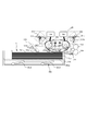
- FIG. 1 is a diagram illustrating a schematic configuration of an image forming apparatus including a sheet feeding device according to a first embodiment of the present invention.
- reference numeral 100 denotes an image forming apparatus
- 100A denotes an image forming apparatus main body (hereinafter referred to as an apparatus main body).
- An image reading unit 41 having an image sensor or the like that irradiates light on a document placed on a platen glass as a document placement table and converts reflected light into a digital signal is provided on the upper part of the apparatus main body 100A.
- a document for reading an image is conveyed onto the platen glass by the automatic document feeder 41a.
- the apparatus main body 100A includes an image forming unit 55, sheet feeding devices 51 and 52 that feed the sheet S to the image forming unit 55, and a sheet reversing unit that reverses the sheet S and conveys it to the image forming unit 55. 59 is provided.
- the image forming unit 55 includes the exposure unit 42 and four process cartridges 43 (43y, 43m, 43) that form toner images of four colors of yellow (Y), magenta (M), cyan (C), and black (Bk). 43c, 43k).
- the image forming unit 55 includes an intermediate transfer unit 44, a secondary transfer unit 56, and a fixing unit 57 disposed above the process cartridge 43.
- the process cartridge 43 includes the photosensitive drum 21 (21y, 21m, 21c, 21k), the charging roller 22 (22y, 22m, 22c, 22k), and the developing roller 23 (23y, 23m, 23c, 23k). I have.
- the process cartridge 43 includes a drum cleaning blade 24 (24y, 24m, 24c, 24k).
- the intermediate transfer unit 44 includes a belt driving roller 26, an intermediate transfer belt 25 stretched around the secondary transfer inner roller 56a, and the like, and a primary transfer roller that contacts the intermediate transfer belt 25 at a position facing the photosensitive drum 21. 27 (27y, 27m, 27c, 27k). Then, as will be described later, a positive transfer bias is applied to the intermediate transfer belt 25 by the primary transfer roller 27 so that toner images having a negative polarity on the photosensitive drum 21 are sequentially transferred to the intermediate transfer belt 25 in a multiple transfer manner. Is done. As a result, a full color image is formed on the intermediate transfer belt 25.
- the secondary transfer unit 56 includes a secondary transfer inner roller 56a, and a secondary transfer outer roller 56b that is in contact with the secondary transfer inner roller 56a via the intermediate transfer belt 25. Then, as described later, a full-color image formed on the intermediate transfer belt 25 is transferred to the sheet S by applying a positive secondary transfer bias to the secondary transfer outer roller 56b.
- the fixing unit 57 includes a fixing roller 57a and a fixing backup roller 57b. Then, the sheet S is nipped and conveyed between the fixing roller 57a and the fixing backup roller 57b, whereby the toner image on the sheet S is pressurized and heated to be fixed to the sheet S.
- the sheet feeding devices 51 and 52 feed cassettes 51a and 52a, which are storage means (stacking means) for storing the sheets S, and the sheets S stored in the cassettes 51a and 52a one by one while being adsorbed by static electricity.
- the sheet adsorption separation feeding parts 51b and 52b which have a function are provided.
- reference numeral 103 denotes a pre-secondary transfer conveyance path for conveying the sheet S fed from the cassettes 51 a and 52 a to the secondary transfer unit 56
- reference numeral 104 denotes two sheets S conveyed to the secondary transfer unit 56.
- This is a pre-fixing transport path for transporting from the next transfer unit 56 to the fixing unit 57
- Reference numeral 105 denotes a post-fixing conveyance path for conveying the sheet S conveyed to the fixing unit 57 from the fixing unit 57 to the switching member 61
- reference numeral 106 denotes a sheet S conveyed to the switching member 61 from the switching member 61 to the paper discharge unit 58. This is a paper discharge path.
- Reference numeral 107 denotes a re-conveying path for conveying the sheet S reversed by the sheet reversing unit 59 to the image forming unit 55 in order to form an image on the back surface of the sheet S on which an image is formed on one side by the image forming unit 55.
- the exposure unit 42 irradiates the surface of the photosensitive drum 21 with laser light based on image information from a personal computer (not shown). At this time, the surface of the photosensitive drum 21 is uniformly charged to a predetermined polarity / potential by the charging roller 22, and when the laser beam is irradiated, the charge of the portion irradiated with the laser beam is attenuated, thereby exposing the photosensitive drum 21. An electrostatic latent image is formed on the surface of the body drum.
- the electrostatic latent image is developed with yellow (Y), magenta (M), cyan (C), and black (Bk) toners respectively supplied from the developing roller 23, and the electrostatic latent image is developed as a toner image.
- Y yellow
- M magenta
- C cyan
- Bk black
- Each color toner image is sequentially transferred to the intermediate transfer belt 25 by the primary transfer bias applied to the primary transfer roller 27, whereby a full color toner image is formed on the intermediate transfer belt 25.
- the sheet feeding devices 51 and 52 separate and feed only one sheet S from the cassettes 51a and 52a by the sheet suction separation feeding units 51b and 52b. Thereafter, the sheet S is detected by the sheet leading edge detection sensors 51c and 52c, and reaches the drawing roller pair 51d and 51e. Further, the sheet S sandwiched between the drawing roller pairs 51d and 51e is sent to the conveyance path 103, and the position of the leading edge is adjusted by coming into contact with the stopped registration roller pairs 62a and 62b.
- the registration roller pair 62a and 62b are driven at a timing at which the full-color toner image on the intermediate transfer belt and the position of the sheet S coincide with each other.
- the sheet S is conveyed to the secondary transfer unit 56, and the full-color toner image is transferred onto the sheet S by the secondary transfer unit 56 by the secondary transfer bias applied to the secondary transfer outer roller 56b. Is done.
- the sheet S on which the full-color toner image has been transferred is conveyed to the fixing unit 57 where the toner of each color is melted and mixed by receiving heat and pressure, and is fixed on the sheet S as a full-color image. Thereafter, the sheet S on which the image is fixed is discharged by a paper discharge unit 58 provided downstream of the fixing unit 57.
- the conveyance direction of the sheet S is reversed by the sheet reversing unit 59 and the sheet S is conveyed to the image forming unit 55 again.
- the sheet feeding apparatus 51 includes the cassette 51a and the sheet suction separation feeding unit 51b that feeds the sheets S stored in the cassette 51a one by one while being sucked by static electricity.
- the sheet feeding device 51 is provided so as to be movable up and down in the cassette 51a.
- the sheet feeding device 51 lifts and lowers the middle plate 301a on which the sheet S is stacked, and the sheet S fed by the sheet suction separation feeding unit 51b.
- a sheet leading edge detection sensor 51c that detects passage is provided.
- the lifting / lowering means 301 includes a lifter 301b rotatably provided below the middle plate 301a, and the middle plate 301a and the uppermost sheet Sa stacked on the middle plate 301a according to the rotation angle of the lifter 301b. Change the position.
- the sheet leading edge detection sensor 51c is disposed in the sheet conveyance path between the sheet suction separation feeding unit 51b and the drawing roller pair 51d and 51e. The success or failure of sheet feeding is detected based on whether or not the sheet leading edge detection sensor 51c detects the sheet S at a predetermined timing.
- the sheet leading edge detection sensor 51c is a non-contact reflective photosensor, which irradiates a detection target with spot light and measures the amount of reflected light to detect the presence or absence of the detection target.
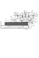
- the sheet adsorbing / separating / feeding unit 51b is flexible to be nipped and conveyed by the first nipping and conveying roller pair 201, the second nipping and conveying roller pair 202, the first nipping and conveying roller pair 201, and the second nipping and conveying roller pair 202. And an endless adsorbing member 200.
- the sheet suction separation and feeding unit 52b provided in the sheet feeding device 52 has the same configuration as the sheet suction separation and feeding unit 51b of the sheet feeding device 51, and thus description thereof is omitted.
- 302 is a paper surface height detecting means for detecting the upper surface position of the sheets S stacked on the intermediate plate 301a.
- the paper surface height detection means 302 is disposed above the intermediate plate 301a and is constituted by a sensor flag 302a and a photosensor 302b.
- the sensor flag 302a is rotatably supported by a support unit (not shown), and one end is disposed at a position where it can come into contact with the upper surface of the uppermost sheet Sa and the other end is disposed at a position where the photosensor 302b can be shielded.
- the control unit 70 shown in FIG. 4 described later detects the upper surface position of the uppermost sheet Sa by detecting the light shielding state of the photosensor 302b. Then, the control unit 70 controls the operation of the elevating unit 301 so that the upper surface of the uppermost sheet Sa is always detected by the paper surface height detecting unit 302, and the position of the middle plate 301a is set to the upper surface height of the uppermost sheet Sa. Is kept at a substantially constant position.
- the gap Lr between the first nipping and conveying roller pair 201 and the second nipping and conveying roller pair 202 and the upper surface of the uppermost sheet Sa is also kept substantially constant.
- the gap between the first nipping and conveying roller pair 201 and the upper surface position of the sheet S and the gap between the second nipping and conveying roller pair 202 and the upper surface position of the sheet S are set equal to Lr.
- the gaps need not necessarily be equal.
- the first nipping / conveying roller pair 201 is disposed downstream of the second nipping / conveying roller pair 202 in the sheet feeding direction, and the first nipping / conveying inner roller (first rotating body) 201a and the first nipping / conveying outside (First clamping member)
- the roller 201b is used.
- the first nipping and conveying inner roller 201a is disposed inside the suction member 200 and is rotatably supported by a shaft support member (not shown) whose arrangement position is fixed, and the first nipping and conveying inner roller 201a is first supported by the first nipping and conveying inner roller 201a.
- the drive from the drive unit 203 is transmitted through a drive transmission unit (not shown).
- the first nipping / conveying outer roller 201b which is a driven rotating member, is disposed outside the first nipping / conveying inner roller 201a with the endless belt-shaped suction member 200 interposed therebetween, and is rotatably supported by a shaft support member (not shown).
- a first pressing spring 201c is connected to a shaft support member (not shown), and the first nipping / conveying outer roller 201b is attached in the axial center direction of the first nipping / conveying inner roller 201a by the first pressing spring 201c.
- the sheet S is clamped together with the first nipping and conveying inner roller 201a.
- the second nipping and conveying roller pair 202 includes a second nipping and conveying inner roller (second rotating body) 202a and a second nipping and conveying outer roller (second nipping member) 202b.
- the second nipping and conveying inner roller 202a is disposed inside the adsorption member 200 similarly to the first nipping and conveying inner roller 201a, and is rotatably supported by a shaft support member (not shown) whose arrangement position is fixed. Further, a driving force is transmitted from the second driving unit 204 to the second nipping and conveying inner roller 202a via a driving transmission unit (not shown).
- the second nipping and conveying outer roller 202b which is a driven rotation member, is disposed outside the second nipping and conveying inner roller 202a with the suction member 200 interposed therebetween, and is supported by a shaft support member (not shown). It is pivotally supported.
- a second pressing spring 202c is connected to a shaft support member (not shown), and the second nipping and conveying outer roller 202b is urged by the second pressing spring 202c in the axial center direction of the second nipping and conveying inner roller 202a.
- the sheet S is clamped together with the second clamping conveyance inner roller 202a.
- a plurality of endless suction members 200 are directed along the sheet feeding direction.
- two endless suction inner rollers 201a and second sandwiching inner rollers which are two rotating members are provided.
- 202a is supported.
- the adsorbing member 200 is more than [double the distance between the rotation centers of the first nipping and conveying inner roller 201a and the second nipping and conveying inner roller 202a + half the length of the circumferential surface of each of the rollers 201a and 202a]. Has a long length.
- the adsorbing member 200 can be bent downward while being rotated (moved) by the rotation of the first nipping and conveying inner roller 201a and the second nipping and conveying inner roller 202a.
- the adsorbing member 200 is It becomes possible to contact the uppermost sheet Sa.
- the suction member 200 when the sheet is sucked and conveyed to the suction member 200, the suction member 200 is elastically deformed after the sheet is sucked to the suction member 200 by static electricity so that the sheets do not rub against each other. It is trying to pull it upwards. Then, the sheet is separated from other sheets by pulling upward while elastically deforming the suction member 200 in this way.
- the length of the adsorbing member 200 is determined so as to ensure the sheet contact area Mn that provides the sheet adsorbing force necessary for the adsorbing separation.
- the suction member 200 is electrically connected to a positive voltage supply unit 205a to which a positive voltage is supplied and a negative voltage supply unit 205b to which a negative voltage is supplied. Then, the electrostatic attraction force that attracts the sheet S to the attraction member 200 by the positive and negative voltages supplied from the positive voltage supply means 205a that is the first power supply and the negative voltage supply means 205b that is the second power supply. appear.
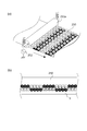
- FIG. 3A is a view showing the surface of the adsorbing member
- FIG. 3B is a perspective view of the adsorbing member 200
- FIG. 3C is a view showing a cross section of the feeding portion of the adsorbing member 200
- FIG. (D) is a diagram showing a concept of electrostatic attraction force acting between the attraction member 200 and the sheet S.
- the adsorbing member 200 includes a base layer 200c, a positive electrode 200a that is a first electrode, and a negative electrode 200b that is a second electrode.
- the positive electrode 200a and the negative electrode 200b each have a comb shape and are alternately arranged inside the base layer 200c.
- the base layer 200c is a polyimide which is a dielectric having a volume resistance of 108 ⁇ cm or more, and the layer thickness is about 100 ⁇ m.
- the positive electrode 200a and the negative electrode 200b are conductors having a volume resistance of 106 ⁇ cm or less, and copper having a layer thickness of about 10 ⁇ m is used.
- the material and thickness of the suction member 200 are adjusted so that the suction member 200 bends downward to form a barrel shape.
- Exposed areas 200d and 200e where the positive electrode 200a and the negative electrode 200b are exposed are provided on the inner peripheral surface of the adsorption member 200 facing the first nipping and conveying inner roller 201a and the second nipping and conveying inner roller 202a.
- the exposed area 200d of the positive electrode 200a has a positive contact 206a connected to the positive voltage supply means 205a
- the exposed area 200e of the negative electrode 200b has a negative contact 206b connected to the negative voltage supply means 205b. In contact.
- a positive voltage of about +1 kV is applied to the positive electrode 200a
- a negative voltage of about -1 kV is applied to the negative electrode 200b.
- Each of the positive contact 206a and the negative contact 206b has a structure in which a carbon brush is caulked on the tip of an elastic metal plate, and the carbon brush contacts the exposed regions 200d and 200e of the positive electrode 200a and the negative electrode 200b. ing.
- the positive contact 206a and the negative contact 206b have elasticity, the positive contact 206a and the negative contact 206b can follow the adsorbing member 200 whose cross-sectional shape changes every moment, and can stably supply power.
- FIG. 4 is a control block diagram of the sheet feeding apparatus 51 according to the present embodiment.
- reference numeral 70 denotes a control unit.
- the control unit 70 includes a first drive means 203, a second drive means 204, a positive voltage supply means 205a, a negative voltage supply means 205b, a timer. 71 etc. are connected.
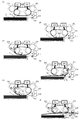
- FIG. 5 is a schematic diagram representing the operation of feeding the sheet S by the sheet adsorption separation feeding unit 51b in time series.
- the sheet S feeding operation is composed of the six steps of the initial operation, the approaching operation, the contact area increasing operation, the suction operation, the separating operation, and the conveying operation shown in FIGS. 5A to 5F in time series order. ing. Hereinafter, these will be described in order.
- the positive voltage supply means 205a and the negative voltage supply means 205b are connected to the suction member 200 in each of the above operation steps, and the suction force is always generated.
- the suction member 200 by increasing the amount of slack downward of the suction member 200, after the stacked sheets are attracted to the suction member 200, the suction member 200 is decreased while decreasing the amount of slack downward of the suction member 200.
- the sheet adsorbed on the sheet is fed. Details will be described below.
- the initial operation shown in FIG. 5A is an operation of disposing the suction member 200 at the initial position of the feeding operation.
- the control unit 70 causes the suction member 200 to be separated from the uppermost sheet Sa by a predetermined gap Lb, and stops the first driving unit 203 and the second driving unit 204. .
- the suction member 200 is bent downward (moving the bent portion downward) to be deformed into a barrel shape, and the suction surface side of the suction member 200 is placed at the uppermost position.
- the controller 70 causes the second driving means 204 to rotate the second nipping and conveying roller pair 202 in the direction of arrow F, and conveys the suction member 200 in the direction of arrow Ad.
- the control unit 70 stops the first nipping and conveying roller pair 201 or rotates the first nipping and conveying roller pair 201 later than the second nipping and conveying roller pair 202 by the first driving unit 203.
- the adsorption member 200 is deformed into a barrel shape. And when the adsorption
- the contact area increasing operation shown in FIG. 5C is a contact between the surface of the suction member 200 that has moved to the position (suction position) for sucking the sheet and the uppermost sheet Sa by continuing such an approaching operation. This is an operation for increasing the area Mc.
- the controller 70 causes the second driving means 204 to rotate the second nipping and conveying roller pair 202 in the direction of arrow F and convey the suction member 200 in the direction of arrow Ad as in the approaching operation.
- the contact area Mc is increased by stopping the first nipping and conveying roller pair 201 or rotating the first nipping and conveying roller pair 201 later than the second nipping and conveying roller pair 202 by the first driving unit 203.
- the contact area increasing operation is continued until the contact area Mc becomes equal to the predetermined contact area.
- a detecting unit that directly detects the size of the contact area Mc may be provided.
- the first and second nipping and conveying roller pairs based on the time measured by the timer 71 for the size of the contact area Mc.
- the detection is performed based on the difference in the conveyance amount between 201 and 202.
- the adsorbing operation shown in FIG. 5D is an operation for adsorbing the uppermost sheet Sa to the adsorbing member 200 after the upper surface of the uppermost sheet Sa and the surface of the adsorbing member 200 are in surface contact with a predetermined contact area Mn. is there.
- the suction member 200 is applied.
- An electrostatic attraction force acts between the sheet S and the sheet S.
- the suction member 200 comes into surface contact with the uppermost sheet Sa with a predetermined contact area Mn, the uppermost sheet Sa is sucked by the suction member 200.
- the controller 70 stops the first driving unit 203 and the second driving unit 204 when the uppermost sheet Sa is adsorbed to the adsorbing member 200.
- the separation operation shown in FIG. 5 (e) is performed by deforming the adsorption member 200 from a barrel shape to a substantially linear shape, thereby elastically deforming the uppermost sheet Sa adsorbed by the adsorption member 200 upward.
- This is an operation of separating from the sheet Sb.
- the control unit 70 causes the first driving unit 203 to rotate the first nipping and conveying roller pair 201 in the direction of arrow F and rotate the suction member 200 in the direction of arrow Au.
- the control unit 70 eliminates the bending by stopping the second nipping and conveying roller pair 202 or rotating the second nipping and conveying roller pair 202 later than the first nipping and conveying roller pair 201 by the second driving unit 204.
- the shape of the adsorption member 200 is deformed into a substantially linear shape. That is, by this separation operation, the suction member 200 moves to a position (separation position) where the uppermost sheet Sa is separated from the lower sheet Sb.
- the suction member 200 deformed into a substantially linear shape is conveyed, whereby the suctioned uppermost sheet Sa is pulled out by a pair of drawing rollers 51d as sheet conveying means downstream of the sheet feeding. , 51e.
- the control unit 70 causes the suction member 200 that has sucked the sheet Sa to be close to the suction surface side by substantially matching the rotation speeds of the first sandwiching and transporting roller pair 201 and the second sandwiching and transporting roller pair 202. Transport while maintaining a linear shape.
- the uppermost sheet Sa while being adsorbed by the adsorbing member 200 is conveyed in the direction of arrow A while maintaining the state where at least the leading end portion separated from the adsorbing member 200 is separated from the lower sheet Sb due to the rigidity of the sheet Sa. Is done. Thereafter, when the leading edge of the uppermost sheet Sa reaches the vicinity of the curved portion of the suction member 200 formed by the first nipping and conveying inner roller 201a, the leading edge of the uppermost sheet Sa peels from the suction member 200. This peeling occurs because the bending reaction force of the sheet Sa is larger than the electrostatic adsorption force generated in the adsorption member 200.
- the magnitude of the electrostatic attraction force generated on the attraction member 200 is set such that the sheet is adsorbed with a force smaller than the bending reaction force of the sheet Sa. That is, the suction member 200 is moved to a position where the uppermost sheet Sa is separated (separated position) by this conveying operation.
- the control unit 70 determines that an error has occurred in the sheet Sa feeding operation, and starts the feeding operation again from the approaching operation. .
- only one uppermost sheet Sa is fed from the plurality of sheets S stacked on the cassette 51a. By repeating these six steps, the sheets S can be continuously fed one by one.
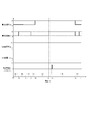
- FIG. 6 is a timing chart of the initial operation, approaching operation, contact area increasing operation, suction operation, separation operation, and transport operation shown in FIG.
- u1 is the conveying speed of the first nipping and conveying roller pair 201
- u2 is the conveying speed of the second nipping and conveying roller pair 202.
- vp is a positive voltage supplied from the positive voltage supply means 205a
- vn is a negative voltage supplied from the negative voltage supply means 205b
- ps is a detection pulse of the sheet leading edge detection sensor 51c.
- the section from time T0 to T1 shown in (a) is the initial operation section.
- the transport speed u1 and transport speed u2 are set to 0, the supply voltage vp is set to + V, and the supply voltage vn is set to ⁇ V. ing.
- the supply voltage vp and the supply voltage vn are + V and ⁇ V in all feeding operations of the sheet S, and do not change.
- the section from time T1 to T2 shown in (b) is an approaching operation section, the transport speed u1 is set to 0, and the transport speed u2 is set to U.
- the section from time T2 to T3 shown in (c) is the contact area increasing operation section, and the transport speed u1 is set to 0 and the transport speed u2 is set to the speed U continuously from time T1.
- the section from time T3 to T4 shown in (d) is an adsorption operation section, and the transport speed u1 and the transport speed u2 are set to zero.
- the section from time T4 to T5 shown in (e) is a separation operation section, the transport speed u1 is set to U, and the transport speed u2 is set to 0.
- the section from time T5 to T6 shown in (f) is a transport operation section, and the transport speed u1 and the transport speed u2 are set to U.
- a tip detection pulse ps is output at time Tp immediately after time T5. Then, the control unit 70 determines the feeding retry depending on whether or not the time Tp is within a predetermined value range. From time T6 to T7 shown in (a) is the initial operation section again, and it is prepared for feeding the next sheet S. Thereafter, continuous sheet feeding is performed by repeating the above operation.
- the suction position where the suction member 200 is brought into surface contact with the sheet and the sheet is sucked, the separation position where the sucked sheet is separated from the lower sheet while the deflection is eliminated, and the sucked sheet Can be moved to a separated position. Then, the adsorption member 200 is rotated to adsorb the sheet, and after the adsorbed sheet is delivered to the pair of drawing rollers 51d and 51e, the adsorption member 200 is stopped at a position away from the sheet (standby position). . As a result, the sheets can be separated and fed without moving the frame carrying the suction member 200, the driving means, the rollers, and the like.
- the configuration of the present embodiment includes a first nipping and conveying outer roller 201b and a first nipping and conveying outer roller 201b that nipping the suction member 200 supported by the first nipping and conveying inner roller 202a and the second nipping and conveying inner roller 201b. 2 nipping and conveying outer roller 202b. Therefore, according to the configuration of the present embodiment, the amount of slack of the adsorption member 200 can be increased (the amount of deformation of the adsorption member 200 can be increased).
- the sheet adsorbed by the adsorbing member 200 can be greatly deformed, so that the adsorbed sheet and the next sheet are separated by the stiffness (rigidity) of the sheet. Can do. Further, in this embodiment, since the amount of slack of the adsorption member 200 is large, the apparent rigidity of the adsorption member 200 can be reduced, so that the sound at the time of contact between the adsorption member 200 and the sheet can be reduced. Moreover, in this embodiment, since the adsorption member 200 is clamped and rotated, the adsorption member 200 can be rotated without slipping. Therefore, even if the sheet is heavy and has a large basis weight, the sheet can be stably adsorbed to the adsorbing member 200.
- the first drive unit 203 and the second drive unit 204 are stopped, but both are driven at a constant speed, and the suction member 200 is moved to a predetermined level with respect to the sheet S. It may be separated by a gap.
- the suction member 200 is moved closer to the sheet S due to the difference in the conveyance speed between the second nipping and conveying roller pair 202 and the first nipping and conveying roller pair 201 to increase the contact area.
- the contact area may be increased by causing the first driving unit 203 to rotate in the opposite direction and stopping the second driving unit 204 to bring the suction member 200 closer to the sheet S.
- control unit 70 rotates the first nipping / conveying roller pair 201 in the direction opposite to the rotation direction of the second nipping / conveying roller pair 202 to increase the amount of slackening of the attracting member 200 to the stacking unit.
- the sheet S loaded on the suction member 200 is sucked by the suction member 200. Thereafter, the sheet S is fed by rotating the first nipping and conveying roller pair 201 in the same direction as the rotation direction of the second nipping and conveying roller pair 202.
- the first drive unit 203 and the second drive unit 204 are stopped. If the uppermost sheet and the suction member 200 are in surface contact with a predetermined contact area Mn, the first drive unit is stopped. 203 and the second driving means 204 may be operating.
- the positive voltage supply means 205a and the negative voltage supply means 205b are connected to the suction member 200 in each of the above-described operation steps, and the suction force is always generated.
- the suction force may be generated by connecting the positive voltage supply unit 205a and the negative voltage supply unit 205b only in the three steps of the suction operation, the separation operation, and the transport operation.
- an electrostatic attracting force is generated between the attracting member 200 and the sheet S with the configuration described above, but the present embodiment is not limited to this.
- the positive electrode 200a and the negative electrode 200b do not need to have a comb-teeth shape, and may have a shape like a uniform electrode in which an electric field is formed between the positive electrode 200a and the negative electrode 200b.
- FIG. 7 is a diagram illustrating the configuration of the sheet feeding apparatus according to the present embodiment.
- the same reference numerals as those in FIG. 2 described above indicate the same or corresponding parts.
- reference numeral 250 denotes a suction member
- reference numeral 251a denotes a charging roller that is provided above the suction member 250 and presses the suction member 250 from above.
- the charging roller 251 a is rotatably supported by a shaft support member (not shown) whose arrangement position is fixed, and is driven to rotate as the suction member 250 moves.
- An AC power source 252 is connected to the charging roller 251a that is the voltage application member. Thereby, a charge is applied to the surface of the suction member 250 by contact charging by the charging roller 251a, and an electrostatic suction force that attracts the sheet S by the applied charge is generated.
- 251b is a backup roller that is provided at a position corresponding to the charging roller 251a on the inner peripheral surface of the suction member 250 and presses the suction member 250 from below in order to stably contact the charging roller 251a and the suction member 250. is there.
- FIG. 8A is a perspective view of the suction member 250
- FIG. 8B shows a cross section of the suction member 250.
- the adsorption member 250 is a resin member having a single-layer structure, and is a dielectric having a volume resistance of 108 ⁇ cm or more.
- An alternating voltage is applied from the charging roller 251 a pressed against the surface of the suction member 250 simultaneously with the transport operation of the suction member 250 by the second sandwiching transport roller pair 202.
- the surface of the adsorption member 250 has a positively charged region at intervals according to the frequency of the AC power supply 252 and the surface movement speed of the adsorption member 250.
- a negatively charged region is formed in a striped pattern.
- An unequal electric field is formed in the vicinity of the surface of the adsorbing member 250 due to the positive and negative charged regions formed in alternating stripes.
- the sheet adsorbing force can be obtained by charging the surface of the adsorbing member from the outside by the charging roller 251a.
- the adsorption member 250 can be charged without disposing an electrode inside the adsorption member, so that the configuration of the adsorption member 250 can be simplified and the cost can be reduced.
- a DC power source may be connected to the charging roller 251a so that a charging region having the same polarity on the entire surface may be formed on the suction member 250 without forming a positive and negative alternating charging region. In this case, although the electrostatic attraction force per unit area becomes small, the electrostatic attraction force can be generated more easily.
- FIG. 9 is a diagram illustrating the configuration of the sheet feeding apparatus according to the present embodiment.
- the same reference numerals as those in FIG. 2 described above indicate the same or corresponding parts.
- 260 is a flexible belt-like adsorbing member
- 261 is a winding roller (first rotating body)
- 262 is a winding roller (second rotating body).
- the winding roller 261 and the unwinding roller 262 are arranged with a predetermined gap Lr from the upper surface of the uppermost sheet Sa stacked on the cassette 51a.
- the take-up roller 261 is disposed downstream of the unwind roller 262 in the sheet feeding direction.
- the suction member 260 has one end fixed to the unwinding roller 262 and the other end fixed to the winding roller 261.
- the gap between the winding roller 261 and the upper surface of the uppermost sheet Sa stacked on the cassette 51a, and the gap between the unwinding roller 262 and the upper surface of the uppermost sheet stacked on the cassette 51a. are equally Lr, but need not be equal.
- the suction member 260 is supported by the two rollers 261 and 262.
- the unwinding roller is the most sheet feeding device. It becomes the first rotating member on the upstream side in the direction.
- the take-up roller is the second rotating member that is the most downstream in the sheet feeding direction.
- the winding roller 261 is rotatably supported by a shaft support member (not shown) whose arrangement position is fixed, and the winding roller 261 is driven by a driving force from the first driving means 203 via a driving transmission means (not shown). Is transmitted.
- the unwinding roller 262 is rotatably supported by a shaft support member (not shown) whose arrangement position is fixed, and the unwinding roller 262 is driven by a driving force from the second driving unit 204 via a driving transmission unit (not illustrated). Is transmitted.
- the first driving means 203 and the second driving means 204 can be rotated in the forward and reverse directions, whereby the winding roller 261 and the unwinding roller 262 can be driven in reverse. become.
- the adsorption member 260 has one end joined to the take-up roller 261 and the other end joined to the take-up roller 262, and is reciprocated by the take-up / rewind operation of the take-up roller 261 and the unwind / rewind operation of the take-up roller 262. Moving. Furthermore, the suction member 260 is located on the side facing the upper surface of the uppermost sheet Sa so as to be in contact with the upper surface of the uppermost sheet Sa.
- the length of the adsorbing member 260 can secure a sheet contact area that provides a sheet adsorbing force necessary for adsorbing separation, and conveys the sheet S to the drawing roller pairs 51d and 51e downstream of the sheet conveyance.
- the length is set to be able to.
- a positive voltage supply unit 205 a and a negative voltage supply unit 205 b are connected to the suction member 260 via a winding roller 261.
- An electrostatic attracting force that attracts the sheet S is generated on the attracting member 260 by the positive and negative voltages applied from the positive voltage supplying unit 205a and the negative voltage supplying unit 205b.
- FIG. 10 is a schematic view of the vicinity of the connection between the adsorption member 260 and the positive voltage supply means 205a and the negative voltage supply means 205b.
- 260c is the base layer of the adsorption member 260, and the base layer 260c has a positive electrode.
- 260a and a negative electrode 260b are arranged.
- Reference numerals 263a and 263b denote joints that are provided at one end in the moving direction of the suction member 260 and are joined to the take-up roller 261.
- Electrode exposed regions 260d and 260e where the positive electrode 260a and the negative electrode 260b are exposed are provided in the vicinity of the ends in the width direction orthogonal to the moving direction of the joints 263a and 263b.
- the winding roller 261 includes an insulating shaft member 261a and conductive power supply rings 261b and 261c that are conductive portions fixed to the outer peripheral surfaces of both ends of the shaft member 261a.
- An electrode exposed region 260d of the attracting member 260 and a power feeding ring 261b of the take-up roller 261 are disposed inside the region of the one joint portion 263a.
- an electrode exposed region 260e and a feeding ring 261c are disposed inside the region of the other joint portion 263b.
- leaf springs 206a and 206b are in contact with the power supply rings 261b and 261c, respectively, and positive and negative voltages are supplied to the leaf springs 206a and 206b from the positive voltage supply means 205a and the negative voltage supply means 205b, respectively. Supplied. And in one junction part 263a, when the positive electrode 260a of the adsorption
- FIG. 11 is a schematic diagram representing the operation of feeding the sheet S by the sheet adsorption separation feeding unit 51b in time series.
- the initial operation shown in FIG. 11A is an operation of placing the suction member 260 at the initial position of the feeding operation.
- the control unit 70 shown in FIG. 4 described above moves the suction member 260 on the sheet S in a predetermined state while the suction member 260 is wound on the unwinding roller 262 side.
- the first driving means 203 and the second driving means 204 are stopped by separating them with the gap Lb.
- the contact operation shown in FIG. 11B is an operation in which the suction surface of the suction member 260 is brought closer to the uppermost sheet Sa by bending the suction member 260 downward.
- the controller 70 causes the second driving unit 204 to rotate the unwind roller 262 in the direction of arrow F to unwind the suction member 260 in the direction of arrow Ad.
- the take-up roller 261 is stopped, or the suction member 260 is bent downward by the first drive means 203 taking up slower than the take-up speed of the take-up roller 262. Then, the surface of the suction member 260 and the uppermost sheet Sa come into contact with each other by bending the suction member 260 downward in this way.
- the contact area increasing operation shown in FIG. 11C is an operation of increasing the contact area Mc between the surface of the adsorption member 260 and the uppermost sheet Sa by continuing such an approaching operation.
- the controller 70 causes the second driving means 204 to rotate the unwind roller 262 in the direction of arrow F and convey the suction member 260 in the direction of arrow Ad, as in the approaching operation.
- the contact area Mc is increased by stopping the winding roller 261 or rotating the winding roller 261 later than the winding roller 262 by the first driving means 203.
- the contact area increasing operation is continued until the contact area Mc becomes equal to a predetermined contact area.
- the size of the contact area Mc is not directly detected, but is instead detected based on the difference in the conveyance amount between the unwinding roller 262 and the winding roller 261.
- 11 (d) is an operation for adsorbing the uppermost sheet Sa in a state where the upper surface of the uppermost sheet Sa and the surface of the adsorbing member 260 are in surface contact with each other with a predetermined contact area Mn.
- the control unit 70 stops the first drive unit 203 and the second drive unit 204 for a predetermined time in a state where the uppermost sheet Sa is adsorbed with a predetermined contact area Mn.
- the uppermost sheet Sa adsorbed by the adsorbing member 260 is changed to the lower sheet Sb by deforming the adsorbing member 260 from a state bent downward to a substantially linear shape. It is the operation to separate from.
- the control unit 70 rotates the winding roller 261 by the first driving unit 203 and winds the suction member 260 in the arrow Au direction.
- the second driving means 204 stops the unwinding roller 262 or unwinds it slower than the winding speed of the winding roller 261, thereby eliminating the bending and deforming the attracting member 260 into a substantially linear shape.
- 11 (f) is an operation of feeding the suctioned uppermost sheet Sa to the drawing roller pairs 51d and 51e by transporting the suction member 260 deformed into a substantially linear shape.
- the control unit 70 sets the suction member 260 that has attracted the uppermost sheet Sa by setting the winding speed of the winding roller 261 and the winding speed of the unwinding roller 262 to be substantially constant. , While the suction surface side is maintained in a substantially linear shape. As a result, the uppermost sheet Sa is conveyed in the direction of arrow A while maintaining a state separated from the lower sheet Sb.
- the leading edge of the uppermost sheet Sa reaches the vicinity of the curved portion of the suction member 260 formed by the winding roller 261
- the leading edge of the sheet Sa is peeled off from the suction member 260.
- This separation occurs because the bending reaction force of the sheet Sa becomes larger than the electrostatic adsorption force generated in the adsorption member 260.
- the sheet Sa is peeled from the front end, but the rear end region is sucked by the suction member 260.
- the sheet is continuously conveyed by the suction member 260, and is transferred to the drawing roller pair 51d and 51e through the leading edge detection by the sheet leading edge detection sensor 51c.
- the control unit 70 determines that an error has occurred in the sheet Sa feeding operation, and starts the feeding operation again from the approaching operation. .
- the sheet Sa is delivered to the pair of drawing rollers 51d and 51e by the conveying operation, and then the first driving unit 203 and the second driving unit 204 are rotated reversely. This is an operation of rewinding the member 260. Then, the suction member 260 is rewound in the direction of a predetermined length arrow B by the take-up roller 261 and the unwind roller 262, whereby the suction member 260 is moved to the standby position that is the initial operation position shown in FIG. Return.
- the suction member 260 is moved to the standby position that is the initial operation position shown in FIG. Return.
- FIG. 12 is a timing chart of the initial operation, approaching operation, contact area increasing operation, adsorption operation, separation operation, transport operation and rewinding operation shown in FIG.
- the section from time T0 to T1 shown in (a) is the initial operation section.
- the transport speed u1 and transport speed u2 are set to 0, the supply voltage vp is set to + V, and the supply voltage vn is set to ⁇ V.
- the section from time T1 to T2 shown in (b) is an approaching operation section, the transport speed u1 is set to 0, and the transport speed u2 is set to U.
- the section from time T2 to T3 shown in (c) is the contact area increasing operation section, and the transport speed u1 is set to 0 and the transport speed u2 is set to the speed U continuously from time T1.
- the section from time T3 to T4 shown in (d) is an adsorption operation section, and the transport speed u1 and the transport speed u2 are set to zero.
- the section from time T4 to T5 shown in (e) is a separation operation section, the transport speed u1 is set to U, and the transport speed u2 is set to 0.
- the section from time T5 to T6 shown in (f) is a transport operation section, and the transport speed u1 and the transport speed u2 are set to U.
- a tip detection pulse ps is output at time Tp immediately after time T5. Then, the control unit 70 determines the feeding retry depending on whether or not the time Tp is within a predetermined value range.
- the section from time T6 to T7 shown in (g) is the rewinding operation section, and the transport speed u1 and the transport speed u2 are set to -Ub.
- the section from time T7 to T8 shown in (a) is an initial operation section, and is prepared for the next sheet S feeding. Thereafter, if the above is repeated, continuous sheet feeding is performed.
- the configuration of the adsorbing member 260 can be further simplified by reducing the shape of the adsorbing member 260 to the end shape instead of the endless shape as in the present embodiment. Can be achieved.
- the adsorbing member 260 in the approaching operation and the contact area increasing operation, the adsorbing member 260 is brought close to the sheet S by the difference between the winding speed of the winding roller 261 and the unwinding speed of the unwinding roller 262, and the contact is made. The area is increased.
- the contact area may be increased by bringing the suction member 260 closer to the sheet S by rotating the first driving unit 203 in the reverse rotation and stopping the second driving unit.
- the first drive unit 203 and the second drive unit 204 are stopped. If the upper surface of the uppermost sheet and the surface of the suction member 260 are in contact with each other with a predetermined area, the first drive is performed.
- the means 203 and the second driving means 204 may be operating.
- the suction member 200 is connected to the positive voltage supply means 205a and the negative voltage supply means 205b and always generates the suction force.
- the present invention is limited to this. is not.
- the adsorbing force may be generated in the adsorbing member 200 by connecting the positive voltage supply means 205a and the negative voltage supply means 205b only in the three steps of the adsorption operation, the separation operation, and the transport operation.
- FIG. 13 is a diagram illustrating the configuration of the sheet feeding apparatus according to the present embodiment. 13, the same reference numerals as those in FIG. 2 described above indicate the same or corresponding parts.
- the sheet suction separation feeding unit 51 b provides a gap Lr ⁇ b> 1 between the uppermost sheet Sa stacked on the cassette 51 a and the second nipping and conveying roller pair 202, and the uppermost sheet Sa and the first sheet Sa1 are separated from each other.
- a gap Lr2 is provided between the pair of nipping and conveying rollers 201. That is, the uppermost sheet Sa and the sheet adsorption separation feeding unit 51b are arranged with an angle of ⁇ .
- the adsorbing member 200 provided in the sheet adsorbing / separating / feeding section 51b has a length capable of adsorbing and separating the uppermost sheet while being sandwiched between the first nipping and conveying roller pair 201 and the second nipping and conveying roller pair 202. Is installed.
- FIG. 14 is a schematic diagram expressing the sheet separation operation.
- the uppermost sheet Sa adsorbed by the adsorbing member 200 is turned up in the direction of the arrow Au along with the separation operation, and is bent and deformed at an angle of approximately ⁇ .
- the drawing roller pairs 51d and 51e that sandwich the sheet Sa after the separation and conveyance operations of the sheet Sa are disposed on an extension line in which the sheet Sa is bent at an angle of approximately ⁇ .
- FIG. 15 is a diagram illustrating the configuration of the sheet feeding apparatus according to the present embodiment. 15, the same reference numerals as those in FIG. 13 described above indicate the same or corresponding parts.
- reference numeral 601 denotes a first nipping / conveying roller pair.
- the first nipping / conveying roller pair 601 is pressed against the first nipping / conveying inner roller 601a by a first nipping / conveying inner roller 601a and a first pressing spring 601c.
- the first nipping / conveying inner roller 601a is disposed inside the adsorption member 200, like the second nipping / conveying inner roller 202a, and is rotatably supported by a shaft support member (not shown) whose arrangement position is fixed.
- the driving from the first driving unit 203 is transmitted to the first nipping and conveying inner roller 601a through a driving transmission unit (not shown).
- the first nipping and conveying roller pair 601 has a function of nipping and conveying the suction member 200 and nipping and conveying the uppermost sheet Sa separated by suction.
- the 651 is a pair of sheet conveyance rollers constituted by two sheet conveyance rollers 651d and 651e, and this sheet conveyance roller pair 651 is provided above the exit of the first nipping conveyance roller pair 601.
- the uppermost sheet Sa nipped and conveyed by the first nipping and conveying roller pair 601 is subsequently nipped and conveyed by the sheet conveying roller pair 651 and is sent to a conveyance path before secondary transfer (not shown).
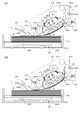
- FIGS. 16A and 16B are schematic views showing before and after the uppermost sheet Sa is nipped by the first nipping and conveying roller pair 601 in the conveying operation.
- the uppermost sheet Sa after the separation operation is the vicinity of the first nipping and conveying roller pair 601 together with the suction member 201 conveyed by the first nipping and conveying roller pair 601 and the second nipping and conveying roller pair 202. Is sucked and conveyed.
- the nip portion of the first nipping and conveying roller pair 601 is disposed on an extension line in the conveying direction of the sheet Sa.
- the sheet Sa in the vicinity of the first nipping / conveying roller pair 601 reaches the nip portion of the first nipping / conveying roller pair 601 and is nipped and conveyed together with the suction member 201 before being separated as it is.
- the sheet Sa nipped and conveyed by the first nipping and conveying roller pair 601 is transferred to the sheet conveying roller pair 651 disposed above the first nipping and conveying roller pair 601 to convey the sheet Sa. The operation is complete.
- the sheet Sa is fed directly above the sheet attraction / separation feeding unit 51b by providing the first nipping and conveying roller pair 601 of the adsorbing member 201 also with the nipping and conveying function of the sheet Sa. It becomes possible to send. As a result, it is not necessary to form a sheet conveyance path on the right side surface of the image forming apparatus main body 100A. Therefore, space saving of the image forming apparatus main body 100A and the number of parts can be reduced.
- the sheet S is attracted to the attracting member by the electrostatic attracting force, but the present invention is not limited to this.
- a fine fiber structure of submicron order may be formed on the adsorbing member and adsorbed by an intermolecular attractive force acting between the sheet S.
Abstract
La présente invention concerne un dispositif d'alimentation en feuilles permettant d'alimenter des feuilles au moyen d'une configuration simple par adsorption électrostatique et avec un bruit faible, et un dispositif de formation d'image. Le dispositif d'alimentation en feuilles comprend un premier rouleau extérieur de maintien et d'acheminement (201b) et un second rouleau extérieur de maintien et d'acheminement (202b) qui maintient un élément d'adsorption (200) supporté par un premier rouleau intérieur de maintien et d'acheminement (202a) et un second rouleau intérieur de maintien et d'acheminement (201a) dans un état dans lequel la surface intérieure s'affaisse.
Priority Applications (3)
| Application Number | Priority Date | Filing Date | Title |
|---|---|---|---|
| CN201480020817.3A CN105121317B (zh) | 2013-04-12 | 2014-04-10 | 片材给送装置和成像装置 |
| US14/776,942 US9561922B2 (en) | 2013-04-12 | 2014-04-10 | Sheet feeding device and image forming apparatus |
| EP14783215.8A EP2985248A4 (fr) | 2013-04-12 | 2014-04-10 | Dispositif d'alimentation en feuilles et dispositif de formation d'image |
Applications Claiming Priority (2)
| Application Number | Priority Date | Filing Date | Title |
|---|---|---|---|
| JP2013-083584 | 2013-04-12 | ||
| JP2013083584 | 2013-04-12 |
Publications (1)
| Publication Number | Publication Date |
|---|---|
| WO2014168209A1 true WO2014168209A1 (fr) | 2014-10-16 |
Family
ID=51689613
Family Applications (1)
| Application Number | Title | Priority Date | Filing Date |
|---|---|---|---|
| PCT/JP2014/060412 WO2014168209A1 (fr) | 2013-04-12 | 2014-04-10 | Dispositif d'alimentation en feuilles et dispositif de formation d'image |
Country Status (5)
| Country | Link |
|---|---|
| US (1) | US9561922B2 (fr) |
| EP (1) | EP2985248A4 (fr) |
| JP (1) | JP6347634B2 (fr) |
| CN (1) | CN105121317B (fr) |
| WO (1) | WO2014168209A1 (fr) |
Cited By (2)
| Publication number | Priority date | Publication date | Assignee | Title |
|---|---|---|---|---|
| WO2016185723A1 (fr) * | 2015-05-20 | 2016-11-24 | Canon Kabushiki Kaisha | Appareil d'alimentation en feuilles et appareil de formation d'image |
| US20170045853A1 (en) * | 2014-06-24 | 2017-02-16 | Canon Kabushiki Kaisha | Sheet feeding apparatus and image forming apparatus |
Families Citing this family (2)
| Publication number | Priority date | Publication date | Assignee | Title |
|---|---|---|---|---|
| JP2016044028A (ja) * | 2014-08-22 | 2016-04-04 | キヤノン株式会社 | シート給送装置及び画像形成装置 |
| JP6584380B2 (ja) * | 2016-10-27 | 2019-10-02 | キヤノン株式会社 | 給送ユニット、給送ユニットを備える給紙装置及び給送装置を備える画像形成装置 |
Citations (6)
| Publication number | Priority date | Publication date | Assignee | Title |
|---|---|---|---|---|
| JPS58202230A (ja) * | 1982-05-18 | 1983-11-25 | Fuji Xerox Co Ltd | 給紙装置 |
| JPS59112839U (ja) * | 1983-01-19 | 1984-07-30 | 富士ゼロックス株式会社 | 用紙送出装置 |
| JPH05139548A (ja) | 1991-11-15 | 1993-06-08 | Ricoh Co Ltd | 給紙装置およびその装置を用いる給紙方法 |
| JPH06255823A (ja) * | 1993-02-26 | 1994-09-13 | Nec Corp | 搬送装置 |
| JP2011168396A (ja) | 2010-02-22 | 2011-09-01 | Ricoh Co Ltd | シート搬送装置および画像形成装置 |
| JP2012140224A (ja) | 2011-01-05 | 2012-07-26 | Ricoh Co Ltd | シート材給送装置、及び画像形成装置 |
Family Cites Families (15)
| Publication number | Priority date | Publication date | Assignee | Title |
|---|---|---|---|---|
| US5305995A (en) | 1989-12-18 | 1994-04-26 | Canon Kabushiki Kaisha | Sheet feeding apparatus for re-feeding a sheet without smearing |
| US5478066A (en) | 1992-11-02 | 1995-12-26 | Canon Kabushiki Kaisha | Sheet supply apparatus |
| US5645274A (en) | 1993-09-22 | 1997-07-08 | Canon Kabushiki Kaisha | Sheet supply apparatus |
| US5722652A (en) | 1993-10-28 | 1998-03-03 | Canon Kabushiki Kaisha | Sheet feeding apparatus with sheet absorb means and a conveyor controlled for forward and reverse conveying directions |
| US5681036A (en) | 1994-10-07 | 1997-10-28 | Canon Kabushiki Kaisha | Sheet feeding device with control of skew-correction |
| JP3862577B2 (ja) * | 2002-02-12 | 2006-12-27 | キヤノン株式会社 | シート給送装置及び画像形成装置 |
| JP4124153B2 (ja) | 2004-03-31 | 2008-07-23 | ブラザー工業株式会社 | プロセスカートリッジおよび画像形成装置 |
| JP4591579B2 (ja) * | 2008-08-29 | 2010-12-01 | ブラザー工業株式会社 | シート案内装置 |
| JP5303250B2 (ja) | 2008-11-28 | 2013-10-02 | 筑波精工株式会社 | 積層対象物の繰出装置と積層対象物の繰出方法 |
| JP5375327B2 (ja) * | 2009-05-20 | 2013-12-25 | 株式会社リコー | シート分離給紙装置および画像形成装置 |
| CN101891069A (zh) * | 2009-05-20 | 2010-11-24 | 株式会社理光 | 片材供送设备及图像形成设备 |
| JP2011042428A (ja) * | 2009-08-19 | 2011-03-03 | Ricoh Co Ltd | シート材分離給送装置および画像形成装置 |
| JP5532392B2 (ja) * | 2009-09-14 | 2014-06-25 | 株式会社リコー | シート材給送装置及びこれを備えた画像形成装置 |
| JP5441757B2 (ja) | 2010-02-23 | 2014-03-12 | キヤノン株式会社 | 画像形成装置 |
| US8523107B2 (en) | 2010-03-12 | 2013-09-03 | The Boeing Company | Fuselage mounted landing gear |
-
2014
- 2014-03-19 JP JP2014056023A patent/JP6347634B2/ja not_active Expired - Fee Related
- 2014-04-10 WO PCT/JP2014/060412 patent/WO2014168209A1/fr active Application Filing
- 2014-04-10 US US14/776,942 patent/US9561922B2/en active Active
- 2014-04-10 EP EP14783215.8A patent/EP2985248A4/fr not_active Withdrawn
- 2014-04-10 CN CN201480020817.3A patent/CN105121317B/zh not_active Expired - Fee Related
Patent Citations (6)
| Publication number | Priority date | Publication date | Assignee | Title |
|---|---|---|---|---|
| JPS58202230A (ja) * | 1982-05-18 | 1983-11-25 | Fuji Xerox Co Ltd | 給紙装置 |
| JPS59112839U (ja) * | 1983-01-19 | 1984-07-30 | 富士ゼロックス株式会社 | 用紙送出装置 |
| JPH05139548A (ja) | 1991-11-15 | 1993-06-08 | Ricoh Co Ltd | 給紙装置およびその装置を用いる給紙方法 |
| JPH06255823A (ja) * | 1993-02-26 | 1994-09-13 | Nec Corp | 搬送装置 |
| JP2011168396A (ja) | 2010-02-22 | 2011-09-01 | Ricoh Co Ltd | シート搬送装置および画像形成装置 |
| JP2012140224A (ja) | 2011-01-05 | 2012-07-26 | Ricoh Co Ltd | シート材給送装置、及び画像形成装置 |
Non-Patent Citations (1)
| Title |
|---|
| See also references of EP2985248A4 |
Cited By (2)
| Publication number | Priority date | Publication date | Assignee | Title |
|---|---|---|---|---|
| US20170045853A1 (en) * | 2014-06-24 | 2017-02-16 | Canon Kabushiki Kaisha | Sheet feeding apparatus and image forming apparatus |
| WO2016185723A1 (fr) * | 2015-05-20 | 2016-11-24 | Canon Kabushiki Kaisha | Appareil d'alimentation en feuilles et appareil de formation d'image |
Also Published As
| Publication number | Publication date |
|---|---|
| CN105121317B (zh) | 2017-04-12 |
| CN105121317A (zh) | 2015-12-02 |
| JP6347634B2 (ja) | 2018-06-27 |
| EP2985248A1 (fr) | 2016-02-17 |
| EP2985248A4 (fr) | 2017-07-12 |
| US9561922B2 (en) | 2017-02-07 |
| US20160031662A1 (en) | 2016-02-04 |
| JP2014218370A (ja) | 2014-11-20 |
Similar Documents
| Publication | Publication Date | Title |
|---|---|---|
| JP5605678B2 (ja) | シート搬送装置および画像形成装置 | |
| US20160289022A1 (en) | Sheet feeding device and image forming apparatus | |
| JP6347634B2 (ja) | シート給送装置及び画像形成装置 | |
| KR101214406B1 (ko) | 화상 형성 장치 | |
| JP2009075356A (ja) | 画像形成装置 | |
| WO2014168207A1 (fr) | Dispositif d'alimentation de feuille et dispositif de formation d'image | |
| WO2014168208A1 (fr) | Dispositif d'alimentation de feuille et dispositif de formation d'image | |
| US8942605B2 (en) | Image forming apparatus | |
| JP2016124705A (ja) | シート給送装置及び画像形成装置 | |
| US8774689B2 (en) | Electrophotographic image forming apparatus | |
| JP2016044028A (ja) | シート給送装置及び画像形成装置 | |
| JP2019104608A (ja) | 静電吸着ベルト、シート給送装置及び画像形成装置 | |
| JP2016008102A (ja) | シート給送装置及び画像形成装置 | |
| JP6478803B2 (ja) | シート給送装置及び画像形成装置 | |
| JP5429634B2 (ja) | シート搬送装置および画像形成装置 | |
| JP2016013878A (ja) | シート給送装置及び画像形成装置 | |
| JP2018177413A (ja) | シート給送装置及び画像形成装置 | |
| JP2009145391A (ja) | 画像形成装置 | |
| JP2017019650A (ja) | シート給送装置及び画像形成装置。 | |
| JP2018177414A (ja) | シート給送装置及び画像形成装置 | |
| JP3295750B2 (ja) | 画像記録装置 | |
| JP2011042428A (ja) | シート材分離給送装置および画像形成装置 | |
| JP2016034868A (ja) | シート給送装置及び画像形成装置 | |
| JP2010037028A (ja) | 用紙分離装置、用紙搬送装置及び画像形成装置 | |
| JP2018116125A (ja) | 転写装置および画像形成装置 |
Legal Events
| Date | Code | Title | Description |
|---|---|---|---|
| 121 | Ep: the epo has been informed by wipo that ep was designated in this application |
Ref document number: 14783215 Country of ref document: EP Kind code of ref document: A1 |
|
| WWE | Wipo information: entry into national phase |
Ref document number: 14776942 Country of ref document: US |
|
| WWE | Wipo information: entry into national phase |
Ref document number: 2014783215 Country of ref document: EP |
|
| NENP | Non-entry into the national phase |
Ref country code: DE |