WO2014168002A1 - 物標検出装置及び車両制御システム - Google Patents
物標検出装置及び車両制御システム Download PDFInfo
- Publication number
- WO2014168002A1 WO2014168002A1 PCT/JP2014/058479 JP2014058479W WO2014168002A1 WO 2014168002 A1 WO2014168002 A1 WO 2014168002A1 JP 2014058479 W JP2014058479 W JP 2014058479W WO 2014168002 A1 WO2014168002 A1 WO 2014168002A1
- Authority
- WO
- WIPO (PCT)
- Prior art keywords
- target
- reflection point
- pair
- vehicle
- information
- Prior art date
- Legal status (The legal status is an assumption and is not a legal conclusion. Google has not performed a legal analysis and makes no representation as to the accuracy of the status listed.)
- Ceased
Links
Images


Classifications
-
- G—PHYSICS
- G01—MEASURING; TESTING
- G01S—RADIO DIRECTION-FINDING; RADIO NAVIGATION; DETERMINING DISTANCE OR VELOCITY BY USE OF RADIO WAVES; LOCATING OR PRESENCE-DETECTING BY USE OF THE REFLECTION OR RERADIATION OF RADIO WAVES; ANALOGOUS ARRANGEMENTS USING OTHER WAVES
- G01S7/00—Details of systems according to groups G01S13/00, G01S15/00, G01S17/00
- G01S7/02—Details of systems according to groups G01S13/00, G01S15/00, G01S17/00 of systems according to group G01S13/00
- G01S7/41—Details of systems according to groups G01S13/00, G01S15/00, G01S17/00 of systems according to group G01S13/00 using analysis of echo signal for target characterisation; Target signature; Target cross-section
-
- B—PERFORMING OPERATIONS; TRANSPORTING
- B60—VEHICLES IN GENERAL
- B60K—ARRANGEMENT OR MOUNTING OF PROPULSION UNITS OR OF TRANSMISSIONS IN VEHICLES; ARRANGEMENT OR MOUNTING OF PLURAL DIVERSE PRIME-MOVERS IN VEHICLES; AUXILIARY DRIVES FOR VEHICLES; INSTRUMENTATION OR DASHBOARDS FOR VEHICLES; ARRANGEMENTS IN CONNECTION WITH COOLING, AIR INTAKE, GAS EXHAUST OR FUEL SUPPLY OF PROPULSION UNITS IN VEHICLES
- B60K35/00—Instruments specially adapted for vehicles; Arrangement of instruments in or on vehicles
- B60K35/20—Output arrangements, i.e. from vehicle to user, associated with vehicle functions or specially adapted therefor
- B60K35/21—Output arrangements, i.e. from vehicle to user, associated with vehicle functions or specially adapted therefor using visual output, e.g. blinking lights or matrix displays
- B60K35/22—Display screens
-
- B—PERFORMING OPERATIONS; TRANSPORTING
- B60—VEHICLES IN GENERAL
- B60K—ARRANGEMENT OR MOUNTING OF PROPULSION UNITS OR OF TRANSMISSIONS IN VEHICLES; ARRANGEMENT OR MOUNTING OF PLURAL DIVERSE PRIME-MOVERS IN VEHICLES; AUXILIARY DRIVES FOR VEHICLES; INSTRUMENTATION OR DASHBOARDS FOR VEHICLES; ARRANGEMENTS IN CONNECTION WITH COOLING, AIR INTAKE, GAS EXHAUST OR FUEL SUPPLY OF PROPULSION UNITS IN VEHICLES
- B60K35/00—Instruments specially adapted for vehicles; Arrangement of instruments in or on vehicles
- B60K35/20—Output arrangements, i.e. from vehicle to user, associated with vehicle functions or specially adapted therefor
- B60K35/28—Output arrangements, i.e. from vehicle to user, associated with vehicle functions or specially adapted therefor characterised by the type of the output information, e.g. video entertainment or vehicle dynamics information; characterised by the purpose of the output information, e.g. for attracting the attention of the driver
-
- B—PERFORMING OPERATIONS; TRANSPORTING
- B60—VEHICLES IN GENERAL
- B60K—ARRANGEMENT OR MOUNTING OF PROPULSION UNITS OR OF TRANSMISSIONS IN VEHICLES; ARRANGEMENT OR MOUNTING OF PLURAL DIVERSE PRIME-MOVERS IN VEHICLES; AUXILIARY DRIVES FOR VEHICLES; INSTRUMENTATION OR DASHBOARDS FOR VEHICLES; ARRANGEMENTS IN CONNECTION WITH COOLING, AIR INTAKE, GAS EXHAUST OR FUEL SUPPLY OF PROPULSION UNITS IN VEHICLES
- B60K35/00—Instruments specially adapted for vehicles; Arrangement of instruments in or on vehicles
- B60K35/20—Output arrangements, i.e. from vehicle to user, associated with vehicle functions or specially adapted therefor
- B60K35/29—Instruments characterised by the way in which information is handled, e.g. showing information on plural displays or prioritising information according to driving conditions
-
- B—PERFORMING OPERATIONS; TRANSPORTING
- B60—VEHICLES IN GENERAL
- B60K—ARRANGEMENT OR MOUNTING OF PROPULSION UNITS OR OF TRANSMISSIONS IN VEHICLES; ARRANGEMENT OR MOUNTING OF PLURAL DIVERSE PRIME-MOVERS IN VEHICLES; AUXILIARY DRIVES FOR VEHICLES; INSTRUMENTATION OR DASHBOARDS FOR VEHICLES; ARRANGEMENTS IN CONNECTION WITH COOLING, AIR INTAKE, GAS EXHAUST OR FUEL SUPPLY OF PROPULSION UNITS IN VEHICLES
- B60K35/00—Instruments specially adapted for vehicles; Arrangement of instruments in or on vehicles
- B60K35/80—Arrangements for controlling instruments
-
- B—PERFORMING OPERATIONS; TRANSPORTING
- B60—VEHICLES IN GENERAL
- B60W—CONJOINT CONTROL OF VEHICLE SUB-UNITS OF DIFFERENT TYPE OR DIFFERENT FUNCTION; CONTROL SYSTEMS SPECIALLY ADAPTED FOR HYBRID VEHICLES; ROAD VEHICLE DRIVE CONTROL SYSTEMS FOR PURPOSES NOT RELATED TO THE CONTROL OF A PARTICULAR SUB-UNIT
- B60W30/00—Purposes of road vehicle drive control systems not related to the control of a particular sub-unit, e.g. of systems using conjoint control of vehicle sub-units
- B60W30/14—Adaptive cruise control
- B60W30/16—Control of distance between vehicles, e.g. keeping a distance to preceding vehicle
-
- G—PHYSICS
- G01—MEASURING; TESTING
- G01S—RADIO DIRECTION-FINDING; RADIO NAVIGATION; DETERMINING DISTANCE OR VELOCITY BY USE OF RADIO WAVES; LOCATING OR PRESENCE-DETECTING BY USE OF THE REFLECTION OR RERADIATION OF RADIO WAVES; ANALOGOUS ARRANGEMENTS USING OTHER WAVES
- G01S13/00—Systems using the reflection or reradiation of radio waves, e.g. radar systems; Analogous systems using reflection or reradiation of waves whose nature or wavelength is irrelevant or unspecified
- G01S13/02—Systems using reflection of radio waves, e.g. primary radar systems; Analogous systems
- G01S13/04—Systems determining presence of a target
-
- G—PHYSICS
- G01—MEASURING; TESTING
- G01S—RADIO DIRECTION-FINDING; RADIO NAVIGATION; DETERMINING DISTANCE OR VELOCITY BY USE OF RADIO WAVES; LOCATING OR PRESENCE-DETECTING BY USE OF THE REFLECTION OR RERADIATION OF RADIO WAVES; ANALOGOUS ARRANGEMENTS USING OTHER WAVES
- G01S13/00—Systems using the reflection or reradiation of radio waves, e.g. radar systems; Analogous systems using reflection or reradiation of waves whose nature or wavelength is irrelevant or unspecified
- G01S13/02—Systems using reflection of radio waves, e.g. primary radar systems; Analogous systems
- G01S13/06—Systems determining position data of a target
- G01S13/08—Systems for measuring distance only
- G01S13/32—Systems for measuring distance only using transmission of continuous waves, whether amplitude-, frequency-, or phase-modulated, or unmodulated
- G01S13/34—Systems for measuring distance only using transmission of continuous waves, whether amplitude-, frequency-, or phase-modulated, or unmodulated using transmission of continuous, frequency-modulated waves while heterodyning the received signal, or a signal derived therefrom, with a locally-generated signal related to the contemporaneously transmitted signal
- G01S13/345—Systems for measuring distance only using transmission of continuous waves, whether amplitude-, frequency-, or phase-modulated, or unmodulated using transmission of continuous, frequency-modulated waves while heterodyning the received signal, or a signal derived therefrom, with a locally-generated signal related to the contemporaneously transmitted signal using triangular modulation
-
- G—PHYSICS
- G01—MEASURING; TESTING
- G01S—RADIO DIRECTION-FINDING; RADIO NAVIGATION; DETERMINING DISTANCE OR VELOCITY BY USE OF RADIO WAVES; LOCATING OR PRESENCE-DETECTING BY USE OF THE REFLECTION OR RERADIATION OF RADIO WAVES; ANALOGOUS ARRANGEMENTS USING OTHER WAVES
- G01S13/00—Systems using the reflection or reradiation of radio waves, e.g. radar systems; Analogous systems using reflection or reradiation of waves whose nature or wavelength is irrelevant or unspecified
- G01S13/02—Systems using reflection of radio waves, e.g. primary radar systems; Analogous systems
- G01S13/50—Systems of measurement based on relative movement of target
- G01S13/58—Velocity or trajectory determination systems; Sense-of-movement determination systems
- G01S13/583—Velocity or trajectory determination systems; Sense-of-movement determination systems using transmission of continuous unmodulated waves, amplitude-, frequency-, or phase-modulated waves and based upon the Doppler effect resulting from movement of targets
- G01S13/584—Velocity or trajectory determination systems; Sense-of-movement determination systems using transmission of continuous unmodulated waves, amplitude-, frequency-, or phase-modulated waves and based upon the Doppler effect resulting from movement of targets adapted for simultaneous range and velocity measurements
-
- G—PHYSICS
- G01—MEASURING; TESTING
- G01S—RADIO DIRECTION-FINDING; RADIO NAVIGATION; DETERMINING DISTANCE OR VELOCITY BY USE OF RADIO WAVES; LOCATING OR PRESENCE-DETECTING BY USE OF THE REFLECTION OR RERADIATION OF RADIO WAVES; ANALOGOUS ARRANGEMENTS USING OTHER WAVES
- G01S13/00—Systems using the reflection or reradiation of radio waves, e.g. radar systems; Analogous systems using reflection or reradiation of waves whose nature or wavelength is irrelevant or unspecified
- G01S13/66—Radar-tracking systems; Analogous systems
- G01S13/72—Radar-tracking systems; Analogous systems for two-dimensional [2D] tracking, e.g. combination of angle and range tracking, track-while-scan radar
-
- G—PHYSICS
- G01—MEASURING; TESTING
- G01S—RADIO DIRECTION-FINDING; RADIO NAVIGATION; DETERMINING DISTANCE OR VELOCITY BY USE OF RADIO WAVES; LOCATING OR PRESENCE-DETECTING BY USE OF THE REFLECTION OR RERADIATION OF RADIO WAVES; ANALOGOUS ARRANGEMENTS USING OTHER WAVES
- G01S13/00—Systems using the reflection or reradiation of radio waves, e.g. radar systems; Analogous systems using reflection or reradiation of waves whose nature or wavelength is irrelevant or unspecified
- G01S13/88—Radar or analogous systems specially adapted for specific applications
- G01S13/93—Radar or analogous systems specially adapted for specific applications for anti-collision purposes
- G01S13/931—Radar or analogous systems specially adapted for specific applications for anti-collision purposes of land vehicles
-
- G—PHYSICS
- G08—SIGNALLING
- G08G—TRAFFIC CONTROL SYSTEMS
- G08G1/00—Traffic control systems for road vehicles
- G08G1/16—Anti-collision systems
-
- G—PHYSICS
- G08—SIGNALLING
- G08G—TRAFFIC CONTROL SYSTEMS
- G08G1/00—Traffic control systems for road vehicles
- G08G1/16—Anti-collision systems
- G08G1/165—Anti-collision systems for passive traffic, e.g. including static obstacles, trees
-
- G—PHYSICS
- G08—SIGNALLING
- G08G—TRAFFIC CONTROL SYSTEMS
- G08G1/00—Traffic control systems for road vehicles
- G08G1/16—Anti-collision systems
- G08G1/166—Anti-collision systems for active traffic, e.g. moving vehicles, pedestrians, bikes
-
- B—PERFORMING OPERATIONS; TRANSPORTING
- B60—VEHICLES IN GENERAL
- B60W—CONJOINT CONTROL OF VEHICLE SUB-UNITS OF DIFFERENT TYPE OR DIFFERENT FUNCTION; CONTROL SYSTEMS SPECIALLY ADAPTED FOR HYBRID VEHICLES; ROAD VEHICLE DRIVE CONTROL SYSTEMS FOR PURPOSES NOT RELATED TO THE CONTROL OF A PARTICULAR SUB-UNIT
- B60W2554/00—Input parameters relating to objects
-
- B—PERFORMING OPERATIONS; TRANSPORTING
- B60—VEHICLES IN GENERAL
- B60W—CONJOINT CONTROL OF VEHICLE SUB-UNITS OF DIFFERENT TYPE OR DIFFERENT FUNCTION; CONTROL SYSTEMS SPECIALLY ADAPTED FOR HYBRID VEHICLES; ROAD VEHICLE DRIVE CONTROL SYSTEMS FOR PURPOSES NOT RELATED TO THE CONTROL OF A PARTICULAR SUB-UNIT
- B60W2554/00—Input parameters relating to objects
- B60W2554/80—Spatial relation or speed relative to objects
-
- B—PERFORMING OPERATIONS; TRANSPORTING
- B60—VEHICLES IN GENERAL
- B60W—CONJOINT CONTROL OF VEHICLE SUB-UNITS OF DIFFERENT TYPE OR DIFFERENT FUNCTION; CONTROL SYSTEMS SPECIALLY ADAPTED FOR HYBRID VEHICLES; ROAD VEHICLE DRIVE CONTROL SYSTEMS FOR PURPOSES NOT RELATED TO THE CONTROL OF A PARTICULAR SUB-UNIT
- B60W2554/00—Input parameters relating to objects
- B60W2554/80—Spatial relation or speed relative to objects
- B60W2554/801—Lateral distance
-
- G—PHYSICS
- G01—MEASURING; TESTING
- G01S—RADIO DIRECTION-FINDING; RADIO NAVIGATION; DETERMINING DISTANCE OR VELOCITY BY USE OF RADIO WAVES; LOCATING OR PRESENCE-DETECTING BY USE OF THE REFLECTION OR RERADIATION OF RADIO WAVES; ANALOGOUS ARRANGEMENTS USING OTHER WAVES
- G01S13/00—Systems using the reflection or reradiation of radio waves, e.g. radar systems; Analogous systems using reflection or reradiation of waves whose nature or wavelength is irrelevant or unspecified
- G01S13/88—Radar or analogous systems specially adapted for specific applications
- G01S13/93—Radar or analogous systems specially adapted for specific applications for anti-collision purposes
- G01S13/931—Radar or analogous systems specially adapted for specific applications for anti-collision purposes of land vehicles
- G01S2013/9321—Velocity regulation, e.g. cruise control
-
- G—PHYSICS
- G01—MEASURING; TESTING
- G01S—RADIO DIRECTION-FINDING; RADIO NAVIGATION; DETERMINING DISTANCE OR VELOCITY BY USE OF RADIO WAVES; LOCATING OR PRESENCE-DETECTING BY USE OF THE REFLECTION OR RERADIATION OF RADIO WAVES; ANALOGOUS ARRANGEMENTS USING OTHER WAVES
- G01S13/00—Systems using the reflection or reradiation of radio waves, e.g. radar systems; Analogous systems using reflection or reradiation of waves whose nature or wavelength is irrelevant or unspecified
- G01S13/88—Radar or analogous systems specially adapted for specific applications
- G01S13/93—Radar or analogous systems specially adapted for specific applications for anti-collision purposes
- G01S13/931—Radar or analogous systems specially adapted for specific applications for anti-collision purposes of land vehicles
- G01S2013/9325—Radar or analogous systems specially adapted for specific applications for anti-collision purposes of land vehicles for inter-vehicle distance regulation, e.g. navigating in platoons
Definitions
- the present invention relates to a target detection device that generates information about a target existing around a vehicle, and a vehicle control system that uses information generated by the target detection device.
- a radar wave laser wave, millimeter wave, etc.
- a reflected wave is received.
- This type of target detection apparatus is applied to a system that performs vehicle control such as so-called auto cruise control (ACC).
- Auto cruise control detects a vehicle (preceding vehicle) traveling in the same lane as the host vehicle in front of the traveling direction of the host vehicle, and controls the vehicle speed so that the distance between the preceding vehicle and the preceding vehicle is kept constant. The vehicle speed is controlled so that the vehicle travels at a predetermined constant speed when the vehicle does not exist (see, for example, Patent Document 1).
- the radar wave is strongly reflected at two points near both ends in the vehicle width direction, such as a two-floor type carrier car in a state where a vehicle that is a load is not loaded, and the two reflection points are Consider a case where a large vehicle that is more than the width of a normal passenger car is a preceding vehicle.
- these two reflection points are based on different targets (for example, two vehicles running in parallel on both adjacent lanes adjacent to the own lane).
- targets for example, two vehicles running in parallel on both adjacent lanes adjacent to the own lane.
- the ACC may perform control by determining that it can pass between both targets.
- an object of the present invention is to suppress erroneous detection of a large target having a plurality of reflection points that strongly reflect radar waves.
- the target detection apparatus of the present invention is mounted on a vehicle and receives information on a radar wave reflected toward the outside of the vehicle, thereby generating information related to the target reflecting the radar wave.
- Point position detection means, target information generation means, counting means, parallel running pair extraction means, and determination means are provided.
- the target information generating means transmits and receives radar waves and detects the position of the reflection point that reflects the radar waves. For each reflection point detected by the reflection point position detection means, there is a possibility that there is a reflection point caused by the same target set with the target reflection point as a reference, with the target reflection point as the target reflection point. The number of reflection points that are present in the target range and have a speed difference from the target reflection point that is equal to or less than a preset same speed determination threshold value is counted.
- the extraction means extracts a parallel running pair that is a pair of reflection points that satisfy a preset parallel running condition.
- the target information generating unit When the count value at least one of the two reflection points constituting the parallel pair extracted by the parallel pair extraction means is equal to or larger than a preset size determination threshold, It is determined that the two reflection points constituting the parallel running pair are caused by the same target.
- the target information generating unit generates target information (information on the target reflecting the radar wave) reflecting the determination result of the determination unit according to the detection result of the reflection point position detection unit.
- the larger the size of the target that causes the target reflection point the more the number of reflection points (possibly due to the same target) that have the same speed as the target reflection point detected around the target reflection point.
- the target that caused the reflection point to be counted may be a large target (for example, a large vehicle) having a larger vehicle width than the own vehicle. High nature. Therefore, when the count value of at least one of the reflection points constituting the parallel running pair exceeds the size determination threshold, it can be determined that the parallel running pair is likely to be caused by the same target.
- the present invention also provides a program for causing a computer to function as each means constituting the target detection device, a target detection method, in addition to the above-described target detection device and vehicle control system including the target detection device as components. It can be realized in various forms such as a vehicle control method.
- a vehicle control system to which the present invention is applied is mounted on a vehicle and, as shown in FIG. 1, an inter-vehicle control electronic control device (hereinafter referred to as “inter-vehicle control ECU”) 30, an engine electronic control device (hereinafter referred to as “engine ECU”). And a brake electronic control device (hereinafter referred to as “brake ECU”) 34.
- inter-vehicle control ECU an inter-vehicle control electronic control device
- engine ECU engine electronic control device
- brake ECU brake electronic control device
- the inter-vehicle control ECU 30 is connected to a radar sensor 1 in addition to an alarm buzzer (not shown), an indicator such as a meter, a cruise control switch, a target inter-vehicle setting switch, and the like.
- the radar sensor 1 is configured as a so-called “millimeter wave radar” of FMCW (Frequency Modulated Continuous Wave) system, and reflects radar waves by transmitting and receiving radar waves in a millimeter wave band that is frequency-modulated.
- the position of the reflected point is detected, and a target such as a vehicle or roadside object is recognized according to the detection result, and target information that is information related to the recognized target is generated and transmitted to the inter-vehicle control ECU 30. .
- FMCW Frequency Modulated Continuous Wave
- the target information whether the target is a large target having a larger width than a normal passenger car (passenger car of a predetermined width) in addition to the distance to the target, the relative speed, the direction in which the target is located A large flag indicating whether or not is included.
- the brake ECU 34 determines a brake pedal state determined based on information from an unillustrated M / C (master cylinder) pressure sensor in addition to detection information (steering angle, yaw rate) from an unillustrated steering sensor and yaw rate sensor. Send to.
- the brake ECU 34 receives a target acceleration, a brake request, and the like from the inter-vehicle control ECU 30, and opens and closes a pressure increase control valve and a pressure reduction control valve provided in the brake hydraulic circuit according to the received information and the determined brake state.
- the brake force is controlled by driving the actuator.
- the engine ECU 32 transmits detection information (vehicle speed, engine control state, accelerator operation state) from a vehicle speed sensor, a throttle opening sensor, and an accelerator pedal opening sensor (not shown) to the inter-vehicle control ECU 30.
- the engine ECU 32 receives a target acceleration, a fuel cut request, and the like from the inter-vehicle control ECU 30, and responds to a throttle actuator that adjusts the throttle opening of the internal combustion engine in accordance with the operating state specified from the received information. Output a drive command.
- the inter-vehicle control ECU 30 receives a vehicle speed and an engine control state from the engine ECU 32 and a steering angle, a yaw rate, a brake control state, and the like from the brake ECU 34. Further, the inter-vehicle control ECU 30 is a control for adjusting the inter-vehicle distance to the preceding vehicle to an appropriate distance based on the set value by the cruise control switch, the target inter-vehicle setting switch, and the target information received from the radar sensor 1. As a command, a target acceleration, a fuel cut request, and the like are transmitted to the engine ECU 32, and a target acceleration, a brake request, and the like are transmitted to the brake ECU 34.
- the inter-vehicle control ECU 30 determines whether or not an alarm has occurred, and sounds an alarm buzzer when an alarm is required. Further, the inter-vehicle control ECU 30 displays an icon or mark indicating that the target as the preceding vehicle is a large target having a larger width than a normal passenger car (passenger car with a predetermined width) on the notification display as necessary. Display.
- the radar sensor 1 includes an oscillator 10, an amplifier 12, a distributor 14, a transmission antenna 16, and a reception antenna unit 20.
- the oscillator 10 generates a high-frequency signal in the millimeter wave band that is modulated so as to have an upstream section in which the frequency increases linearly with time and a downstream section in which the frequency decreases linearly.
- the amplifier 12 amplifies the high frequency signal generated by the oscillator 10.
- the distributor 14 distributes the output of the amplifier 12 to the transmission signal Ss and the local signal L.
- the reception antenna unit 20 includes a distributor 14, a transmission antenna 16 that radiates a radar wave corresponding to the transmission signal Ss, and n reception antennas that receive the radar wave.
- the radar sensor 1 includes a reception switch 21, an amplifier 22, a mixer 23, a filter 24, an A / D (Analog-to-Digital) converter 25, and a signal processing unit 26.
- the reception switch 21 sequentially selects one of the antennas constituting the reception antenna unit 20, and supplies the reception signal Sr from the selected antenna to the subsequent stage.
- the amplifier 22 amplifies the reception signal Sr supplied from the reception switch 21.
- the mixer 23 mixes the reception signal Sr amplified by the amplifier 22 and the local signal L to generate a beat signal BT.
- the filter 24 removes unnecessary signal components from the beat signal BT generated by the mixer 23.
- the A / D converter 25 samples the output of the filter 24 and converts it into digital data.
- the signal processing unit 26 performs processing for controlling the start / stop of the oscillator 10 and the sampling of the beat signal BT via the A / D converter 25 and the A / D converter 25. Further, the signal processing unit 26 performs signal processing using the sampling data and communication with the inter-vehicle control ECU 30, information necessary for signal processing (vehicle speed information), and information obtained as a result of the signal processing (target Information etc.) is also sent and received.
- each antenna constituting the receiving antenna unit 20 is set so that the beam width thereof includes the entire beam width of the transmitting antenna 16.
- Each antenna is assigned to CH1 to CHn.
- the signal processing unit 26 is configured around a known microcomputer, and further, an arithmetic processing device for executing a fast Fourier transform (FFT) process or the like on the data taken in via the A / D converter 25.
- FFT fast Fourier transform
- a DSP Digital Signal Processor
- the distributor 14 when the oscillator 10 is started in accordance with a command from the signal processing unit 26, the distributor 14 generates a high-frequency signal generated by the oscillator 10 and amplified by the amplifier 12, and the distributor 14 uses power. By distributing, the transmission signal Ss and the local signal L are generated, and the transmission signal Ss is transmitted as a radar wave through the transmission antenna 16.
- the reception switch 21 is switched so that all the channels CH1 to CHn are selected a predetermined number of times (for example, 512 times) during one modulation period of the radar wave.
- the A / D converter 25 performs sampling in synchronization with the switching timing. That is, during one modulation period of the radar wave, sampling data is accumulated for each channel CH1 to CHn and for each up / down section of the radar wave.
- This process is started repeatedly with one modulation period of the radar wave as the measurement cycle.
- step S110 frequency analysis processing (in this case, FFT processing) is performed on sampling data for one modulation period accumulated during the previous measurement cycle, and each of the channels CH1 to CHn and the radar wave is detected.
- the power spectrum of the beat signal BT is calculated for each up / down interval.
- step S120 a peak search is performed to extract a frequency component that is a peak on the power spectrum obtained in step S110 (hereinafter referred to as “peak frequency component”).
- peak frequency component a frequency component that is a peak on the power spectrum obtained in step S110
- the peak frequency components extracted by this peak search include those that match a predicted value in step S180, which will be described later, and others. Further, if there is no peak frequency component that matches the predicted value, it is assumed that the peak frequency component is buried in noise or other peak frequency components, and extrapolation of the peak frequency component is performed. Note that “matching” means matching within a preset allowable range. The signal level of the extrapolated peak frequency component is set to zero or the noise level.
- step S130 for each peak frequency component extracted in step S120 (excluding the extrapolated one) and for each modulation section, an azimuth calculation process for obtaining the arrival direction of the reflected wave that generated the peak frequency is executed.
- frequency analysis processing here, FFT processing or super resolution method such as MUSIC (Multiple Signal Classification) method
- MUSIC Multiple Signal Classification
- step S140 pair matching processing for setting a combination of the peak frequency component during uplink modulation and the peak frequency component during downlink modulation extracted in step S120 is executed. Specifically, the signal levels of the peak frequency components extracted in step S120 and the arrival directions calculated in step S130 are substantially matched (the difference between the two is equal to or less than a preset match determination threshold). Further, for each set combination, the distance and relative speed are calculated using a well-known method in the FMCW radar, and only those whose calculated distance and the calculated speed are smaller than the preset upper limit distance and upper limit speed are formalized. Register as a pair. In addition, since the position indicated by the registered pair is the position of the reflection point existing on the target that reflects the radar wave, the registered pair is also referred to as a reflection point in the following.
- each pair (reflection point) registered in step S140 exists within the target range set with reference to the target reflection point that is the target reflection point, and the velocity with the target reflection point.
- the number of reflection points whose difference is equal to or less than a preset same speed determination threshold value (for example, 5 km / s) is counted.
- this count value is referred to as a reflection point count value.
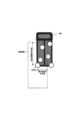
- the target range is equal to or less than the vertical position selection determination value (5 m in the present embodiment) in which the vertical position difference from the target reflection point is set in advance, and the horizontal position difference from the target reflection point is set in advance.
- a rectangular range that is equal to or less than the horizontal position selection determination value (1 m in this embodiment) is used (see FIG. 3).
- the vertical position selection determination value and the horizontal position selection determination value are set so as to cover a range in which a reflection point caused by the same target as the target reflection point may be detected.
- step S160 for each pair registered in S140 of the current measurement cycle (hereinafter referred to as “current cycle pair”), these current cycle pairs are registered in step S140 of the previous measurement cycle (hereinafter referred to as “current cycle pair”).
- a history tracking process is executed to determine whether or not it represents the same target as “previous cycle pair” (whether there is a history connection).
- the predicted position and predicted speed of the current cycle pair corresponding to the previous cycle pair are calculated based on the information of the previous cycle pair.
- the difference (position difference, speed difference) between the predicted position and predicted speed and the detected position and detected speed obtained from the current cycle pair is smaller than the preset upper limit values (upper limit position difference and upper limit speed difference)
- the preset upper limit values upper limit position difference and upper limit speed difference
- step S170 the target recognized in step S160 of the current cycle is the current cycle target, and the target recognized in step S160 of the previous cycle is the previous cycle target. If there is a target, an extrapolation pair is created based on the predicted value for the previous cycle target, and a target extrapolation process is performed to add the extrapolated pair to the current cycle target.
- an extrapolation flag indicating the presence or absence of extrapolation and an extrapolation counter indicating the number of times of extrapolation are set for each current cycle target. If the current cycle target is an actual pair actually detected, the extrapolation flag and extrapolation counter are cleared to zero. If the current cycle target is an extrapolation pair, the extrapolation flag is set to 1 and the extrapolation counter is incremented. When the count value of the extrapolation counter reaches a preset discard threshold, the target is discarded as lost.
- step S180 for each of the current cycle targets registered in steps S160 and S170, the next cycle target prediction process for obtaining the peak frequency to be detected in the next cycle and the azimuth angle to be detected is executed.
- step S190 among the current cycle targets registered in steps S160 and S170, there exists a pair of targets (that is, reflection points) that satisfy a preset parallel running condition (hereinafter referred to as “parallel running pair”). Determine whether or not.
- the parallel pair of interest is within an interval determination threshold (3 m in the present embodiment) in which the mutual interval is set in advance, and the distance difference from the own vehicle to each reflection point of the parallel pair Is equal to or less than the preset parallel running determination threshold (1 m in the present embodiment), the parallel running condition is satisfied.
- the interval determination threshold value is set to be at least larger than the lateral position selection determination value and about the size of a standard lane width.
- step S190 When there is a parallel running pair (step S190: YES), the process proceeds to step S200, and at least one of the reflection point count values of the two current cycle targets constituting the parallel running pair has a preset size. It is determined whether or not a determination threshold value (for example, 6) or more. Note that the size determination threshold is set in advance to a value that can determine whether or not the target is a large target having a width larger than the vehicle width of the host vehicle based on experimental results and the like. The size determination threshold value may be 1. That is, it may be determined that the target is a large target when one or more reflected waves satisfying the predetermined condition shown in step S150 are present (counted).
- a determination threshold value for example, 6
- step S200 When at least one of the reflection point count values is equal to or larger than the size determination threshold value (step S200: YES), the process proceeds to step S210, and both of the two current cycle targets constituting the parallel running pair are attributed to the same target. The size information indicating that the other current cycle target is a large target is added, and the process returns to step S190. On the other hand, if any of the reflection point count values is less than the threshold value (step S200: NO), step S210 is skipped and the process returns to step S190. Note that the processing in steps S190 to S210 is repeatedly executed for all parallel running pairs.
- step S190 If the parallel running pair does not originally exist or the processing of steps S190 to S210 is completed for all the parallel running pairs (step S190: NO), the process proceeds to step S220, and the target is based on the current cycle target. Information is generated, the generated target information is transmitted to the inter-vehicle distance control ECU 30, and the present process is terminated.
- the two current cycle targets are combined into one target, and the middle of both is the target's Target information is generated with the position as the position and the distance between the two as the width of the target.
- the inter-vehicle control ECU 30 generates a plurality of current cycle targets based on reflected waves from a plurality of reflection points on the same large vehicle, and the distance between the two is so far as to pass through by the own vehicle. Even if it is, it is possible to improve the safety and reliability of the auto-cruise control because it is possible to suppress erroneous detection as two targets running in parallel.
- the reflection point count (step S150) is executed after the pair match (step S140), but after the history tracking / target recognition (step S160) and before the step S190. It may be configured to execute.
- the history tracking reduces the number of reflection points from which the number of reflection points should be counted, so the processing load can be reduced.
- the target information is generated using the parallel pair to which the size information is added as one target, but each of the current cycle targets (reflection points) constituting the parallel pair. May be configured to generate target information with size information.
- the inter-vehicle control ECU 30 that receives the provision of the target information may determine whether or not the vehicle can pass between the parallel running pairs based on the size information, and execute auto-cruise control according to the determination result.
Landscapes
- Engineering & Computer Science (AREA)
- Remote Sensing (AREA)
- Radar, Positioning & Navigation (AREA)
- Physics & Mathematics (AREA)
- General Physics & Mathematics (AREA)
- Computer Networks & Wireless Communication (AREA)
- Mechanical Engineering (AREA)
- Transportation (AREA)
- Chemical & Material Sciences (AREA)
- Combustion & Propulsion (AREA)
- Automation & Control Theory (AREA)
- Electromagnetism (AREA)
- Signal Processing (AREA)
- Radar Systems Or Details Thereof (AREA)
- Traffic Control Systems (AREA)
- Control Of Driving Devices And Active Controlling Of Vehicle (AREA)
Abstract
Description
本発明が適用された車両制御システムは、車両に搭載され、図1に示すように、車間制御電子制御装置(以下「車間制御ECU」と称す。)30、エンジン電子制御装置(以下「エンジンECU」と称す。)32、ブレーキ電子制御装置(以下「ブレーキECU」と称す。)34を備える。これらはLAN(Local Area Network)通信バスを介して互いに接続されている。また、各ECU30、32、34は、いずれも周知のマイクロコンピュータを中心に構成され、少なくともLAN通信バスを介して行うためのバスコントローラを備えている。
ここで、レーダセンサ1の詳細について説明する。
このように構成された本実施形態のレーダセンサ1では、信号処理部26からの指令に従って発振器10が起動すると、その発振器10が生成し、増幅器12が増幅した高周波信号を、分配器14が電力分配することにより、送信信号Ss及びローカル信号Lを生成し、このうち送信信号Ssは、送信アンテナ16を介してレーダ波として送出される。
次に、信号処理部26が実行する物標検出処理を、図2に示すフローチャートに沿って説明する。なお、信号処理部26を構成するROM(Read Only Memory)には、本処理のプログラムが少なくとも記憶されている。
以上説明したように、レーダセンサ1では、並走ペアが検出された場合に、反射点数カウント値から、並走ペアの起因となった物標が、自車両より大きい車幅を有した大型の物標(大型車両等)であるか否かを推定する。大型の物標であると推定した場合は、並走ペアは、単一の物標に起因するものとして単一の物標情報を生成する。
以上、本発明の実施形態について説明したが、本発明は、上記実施形態に限定されることなく、種々の形態を採り得ることは言うまでもない。例えば、一つの構成要素が有する機能を複数の構成要素に分散させたり、複数の構成要素が有する機能を一つの構成要素に統合したりしてもよい。また、上記実施形態の構成の少なくとも一部を、同様の機能を有する公知の構成に置き換えてもよい。
20…受信アンテナ部 21…受信スイッチ 22…増幅器 23…ミキサ 24…フィルタ 25…A/D変換器 26…信号処理部 30…車間制御ECU 32…エンジンECU 34…ブレーキECU
Claims (10)
- 車両に搭載され、前記車両の外部に向けて送信したレーダ波の反射波を受信することによって、前記レーダ波を反射した物標に関する情報を生成する物標検出装置であって、
レーダ波を送受信して、前記レーダ波を反射した反射点の位置を検出する反射点位置検出手段(S110~S140)と、
前記反射点位置検出手段での検出結果に従って、前記レーダ波を反射した物標に関する情報を生成する物標情報生成手段(S220)と、
前記反射点位置検出手段で検出された反射点毎に、着目する前記反射点を対象反射点として、該対象反射点を基準にして設定される対象範囲内に存在し、且つ、前記対象反射点との速度差が予め設定された同速判定閾値以下である前記反射点の数をカウントするカウント手段(S150)と、
予め設定された並走条件を満たす前記反射点のペアである並走ペアを抽出する並走ペア抽出手段(S190)と、
前記並走ペア抽出手段にて抽出された並走ペアを構成する二つの反射点のうち少なくとも一方の前記カウント手段でのカウント値が、予め設定されたサイズ判定閾値以上である場合に、該並走ペアを構成する二つの前記反射点は同一物標に起因すると判断する判断手段(S200~S210)と、を備え、
前記物標情報生成手段は、前記判断手段での判断結果を反映した物標情報を生成することを特徴とする物標検出装置。 - 前記並走ペア抽出手段は、前記並走ペア間の間隔が前記車両の車幅より広く設定された間隔判定閾値以下であり、且つ、前記車両から前記並走ペアを構成する各反射点までの距離差が並走判定閾値以下であり、且つ、前記並走ペアの速度差が前記同速判定閾値以下であることを、前記並走条件として用いることを特徴とする請求項1に記載の物標検出装置。
- 前記物標情報生成手段は、前記判断手段にて同一物標に基づくと判断された前記並走ペアから、一つの物標に関する前記物標情報を生成することを特徴とする請求項1または請求項2に記載の物標検出装置。
- 前記物標情報生成手段は、前記反射点毎に前記物標情報を生成し、前記判断手段にて同一物標に基づくと判断された前記並走ペアを構成する各反射点に基づく前記物標情報に、同一物標に基づく他の物標情報が存在する大型の物標であることを表すサイズ情報を付加することを特徴とする請求項1または請求項2に記載の物標検出装置。
- 前記判断手段に基づき、先行車両となる物標が所定横幅の乗用車より大きな横幅を有する大型の物標であることが判断される場合、大型の物標を示す図形を報知表示器に表示させることを特徴とする請求項1ないし請求項4のいずれか1項に記載の物標検出装置。
- 車両に搭載され、前記車両の外部に向けて送信したレーダ波の反射波を受信することによって、前記レーダ波を反射した物標に関する情報を生成する物標検出装置(1)と、
前記物標検出装置により生成された物標情報に従ってオートクルーズコントロールを実行する制御手段(30)と、を備え、
前記物標検出装置は、
レーダ波を送受信して、前記レーダ波を反射した反射点の位置を検出する反射点位置検出手段と、
前記反射点位置検出手段での検出結果に従って、前記レーダ波を反射した物標に関する情報を生成する物標情報生成手段と、
前記反射点位置検出手段で検出された反射点毎に、着目する前記反射点を対象反射点として、該対象反射点を基準にして設定される対象範囲内に存在し、且つ、前記対象反射点との速度差が予め設定された同速判定閾値以下である前記反射点の数をカウントするカウント手段と、
予め設定された並走条件を満たす前記反射点のペアである並走ペアを抽出する並走ペア抽出手段と、
前記並走ペア抽出手段にて抽出された並走ペアを構成する二つの反射点のうち少なくとも一方の前記カウント手段でのカウント値が、予め設定されたサイズ判定閾値以上である場合に、該並走ペアを構成する二つの前記反射点は同一物標に起因すると判断する判断手段と、を備え、
前記物標情報生成手段は、前記判断手段での判断結果を反映した物標情報を生成するものであって、前記反射点毎に前記物標情報を生成し、前記判断手段にて同一物標に基づくと判断された前記並走ペアを構成する各反射点に基づく前記物標情報に、同一物標に基づく他の物標情報が存在する大型の物標であることを表すサイズ情報を付加し、
前記制御手段は、前記物標情報に付加されたサイズ情報に従って、前記同一物標に基づくと判断された前記並走ペアの間を通り抜け不能であるものとして、前記オートクルーズコントロールを実行することを特徴とする車両制御システム。 - 前記並走ペア抽出手段は、前記並走ペア間の間隔が前記車両の車幅より広く設定された間隔判定閾値以下であり、且つ、前記車両から前記並走ペアを構成する各反射点までの距離差が並走判定閾値以下であり、且つ、前記並走ペアの速度差が前記同速判定閾値以下であることを、前記並走条件として用いることを特徴とする請求項6に記載の車両制御システム。
- 前記判断手段に基づき、先行車両となる物標が所定横幅の乗用車より大きな横幅を有する大型の物標であることが判断される場合、大型の物標を示す図形を報知表示器に表示させることを特徴とする請求項6または7に記載の車両制御システム。
- 車両に搭載され、前記車両の外部に向けて送信したレーダ波の反射波を受信することによって、前記レーダ波を反射した物標に関する情報を生成する物標検出方法であって、
レーダ波を送受信して、前記レーダ波を反射した反射点の位置を検出し、
該検出結果に従って、前記レーダ波を反射した物標に関する情報を生成し、
検出された反射点毎に、着目する前記反射点を対象反射点として、該対象反射点を基準にして設定される対象範囲内に存在し、且つ、前記対象反射点との速度差が予め設定された同速判定閾値以下である前記反射点の数をカウントし、
予め設定された並走条件を満たす前記反射点のペアである並走ペアを抽出し、
抽出された並走ペアを構成する二つの反射点のうち少なくとも一方のカウント値が、予め設定されたサイズ判定閾値以上である場合に、該並走ペアを構成する二つの前記反射点は同一物標に起因すると判断し、
該判断結果を反映した物標情報を生成することを特徴とする物標検出方法。 - 車両に搭載され、前記車両の外部に向けて送信したレーダ波の反射波を受信することによって、前記レーダ波を反射した物標に関する情報を生成し、生成された物標情報に従ってオートクルーズコントロールを実行する車両制御方法であって、
レーダ波を送受信して、前記レーダ波を反射した反射点の位置を検出し、
該検出結果に従って、前記レーダ波を反射した物標に関する情報を生成し、
検出された反射点毎に、着目する前記反射点を対象反射点として、該対象反射点を基準にして設定される対象範囲内に存在し、且つ、前記対象反射点との速度差が予め設定された同速判定閾値以下である前記反射点の数をカウントし、
予め設定された並走条件を満たす前記反射点のペアである並走ペアを抽出し、
抽出された並走ペアを構成する二つの反射点のうち少なくとも一方のカウント値が、予め設定されたサイズ判定閾値以上である場合に、該並走ペアを構成する二つの前記反射点は同一物標に起因すると判断し、
該判断結果を反映した物標情報を生成し、
前記反射点毎に前記物標情報を生成し、同一物標に基づくと判断された前記並走ペアを構成する各反射点に基づく前記物標情報に、同一物標に基づく他の物標情報が存在する大型の物標であることを表すサイズ情報を付加し、
前記物標情報に付加されたサイズ情報に従って、前記同一物標に基づくと判断された前記並走ペアの間を通り抜け不能であるものとして、前記オートクルーズコントロールを実行することを特徴とする車両制御方法。
Priority Applications (3)
| Application Number | Priority Date | Filing Date | Title |
|---|---|---|---|
| US14/783,603 US9618608B2 (en) | 2013-04-11 | 2014-03-26 | Target detection apparatus and vehicle control system |
| CN201480020795.0A CN105393136B (zh) | 2013-04-11 | 2014-03-26 | 物标检测装置以及车辆控制系统 |
| DE112014001905.4T DE112014001905B4 (de) | 2013-04-11 | 2014-03-26 | Zielerfassungsvorrichtung und Zielerfassungsverfahren |
Applications Claiming Priority (2)
| Application Number | Priority Date | Filing Date | Title |
|---|---|---|---|
| JP2013-082995 | 2013-04-11 | ||
| JP2013082995A JP6020321B2 (ja) | 2013-04-11 | 2013-04-11 | 物標検出装置及び車両制御システム |
Publications (1)
| Publication Number | Publication Date |
|---|---|
| WO2014168002A1 true WO2014168002A1 (ja) | 2014-10-16 |
Family
ID=51689414
Family Applications (1)
| Application Number | Title | Priority Date | Filing Date |
|---|---|---|---|
| PCT/JP2014/058479 Ceased WO2014168002A1 (ja) | 2013-04-11 | 2014-03-26 | 物標検出装置及び車両制御システム |
Country Status (5)
| Country | Link |
|---|---|
| US (1) | US9618608B2 (ja) |
| JP (1) | JP6020321B2 (ja) |
| CN (1) | CN105393136B (ja) |
| DE (1) | DE112014001905B4 (ja) |
| WO (1) | WO2014168002A1 (ja) |
Cited By (1)
| Publication number | Priority date | Publication date | Assignee | Title |
|---|---|---|---|---|
| US9618608B2 (en) | 2013-04-11 | 2017-04-11 | Denso Corporation | Target detection apparatus and vehicle control system |
Families Citing this family (31)
| Publication number | Priority date | Publication date | Assignee | Title |
|---|---|---|---|---|
| JP6534808B2 (ja) * | 2014-11-28 | 2019-06-26 | 株式会社デンソーテン | レーダ装置、および、信号処理方法 |
| JP6410178B2 (ja) * | 2015-01-08 | 2018-10-24 | パナソニックIpマネジメント株式会社 | 物体検出装置および物体検出方法 |
| JP6507697B2 (ja) * | 2015-02-12 | 2019-05-08 | 株式会社デンソー | 発電制御装置 |
| JP6561584B2 (ja) * | 2015-05-27 | 2019-08-21 | 株式会社デンソー | 車両制御装置、及び車両制御方法 |
| US10393872B2 (en) * | 2015-12-08 | 2019-08-27 | Garmin Switzerland Gmbh | Camera augmented bicycle radar sensor system |
| US10605920B2 (en) * | 2016-01-13 | 2020-03-31 | Ams Sensors Singapore Pte. Ltd. | Power savings through refresh control for distance sensing devices |
| JP6701983B2 (ja) * | 2016-06-02 | 2020-05-27 | 株式会社デンソー | 物標検出装置 |
| JP2017223589A (ja) * | 2016-06-16 | 2017-12-21 | 株式会社デンソーテン | レーダ装置および信号処理方法 |
| JP2017227529A (ja) * | 2016-06-22 | 2017-12-28 | パナソニックIpマネジメント株式会社 | レーダ装置および追従対象決定方法 |
| JP6597517B2 (ja) * | 2016-08-10 | 2019-10-30 | 株式会社デンソー | 物標検出装置 |
| DE102017206569B3 (de) * | 2017-04-19 | 2018-07-05 | Robert Bosch Gmbh | Regelungsverfahren zur Windschattenfahrt eines Zweirads, Steuergerät und Zweirad |
| JP7074438B2 (ja) * | 2017-09-05 | 2022-05-24 | トヨタ自動車株式会社 | 自車位置推定装置 |
| EP3517996B1 (en) * | 2018-01-25 | 2022-09-07 | Aptiv Technologies Limited | Method for determining the position of a vehicle |
| EP3518001B1 (en) | 2018-01-25 | 2020-09-16 | Aptiv Technologies Limited | Method for increasing the reliability of determining the position of a vehicle on the basis of a plurality of detection points |
| JP7188894B2 (ja) * | 2018-03-16 | 2022-12-13 | 株式会社デンソーテン | レーダ装置及び信号処理方法 |
| JP6973302B2 (ja) * | 2018-06-06 | 2021-11-24 | トヨタ自動車株式会社 | 物標認識装置 |
| US10830872B2 (en) * | 2018-06-07 | 2020-11-10 | Fca Us Llc | Vehicle multi-radar relative phase interferometry alignment systems and methods |
| CN111722196A (zh) * | 2019-03-19 | 2020-09-29 | 富士通株式会社 | 雷达反射点提取方法和装置 |
| CN111699407B (zh) * | 2019-03-29 | 2024-08-02 | 深圳市卓驭科技有限公司 | 微波雷达检测栅栏附近静止物体的方法和毫米波雷达 |
| EP3819663B1 (en) | 2019-11-07 | 2025-08-27 | Aptiv Technologies AG | Method for determining a position of a vehicle |
| KR102794170B1 (ko) * | 2019-11-18 | 2025-04-09 | 현대모비스 주식회사 | 후방 교차 충돌 감지 시스템 및 방법 |
| EP3828587B1 (en) | 2019-11-29 | 2025-06-18 | Aptiv Technologies AG | Method for determining the position of a vehicle |
| EP3851870B1 (en) | 2020-01-14 | 2025-08-27 | Aptiv Technologies AG | Method for determining position data and/or motion data of a vehicle |
| KR102805917B1 (ko) * | 2020-01-20 | 2025-05-12 | 삼성전자주식회사 | 객체 검출 장치 및 이를 포함하는 차량 제어 시스템 |
| CN115298566A (zh) * | 2020-03-30 | 2022-11-04 | 三菱电机株式会社 | 物体检测系统和物体检测方法 |
| JP7486355B2 (ja) * | 2020-06-18 | 2024-05-17 | 古野電気株式会社 | 船舶用物標検出システム、船舶用物標検出方法、信頼度推定装置、及びプログラム |
| JP7318600B2 (ja) * | 2020-07-06 | 2023-08-01 | トヨタ自動車株式会社 | 車両及び他車両の認識方法 |
| KR102667971B1 (ko) * | 2020-12-24 | 2024-05-22 | 주식회사 에이치엘클레무브 | 객체 크기 추정 장치 및 방법 |
| CN115236651B (zh) * | 2021-12-17 | 2025-07-22 | 上海仙途智能科技有限公司 | 障碍物检测方法和电子设备 |
| WO2023205444A1 (en) | 2022-04-22 | 2023-10-26 | Velo.Ai, Inc. | Artificially intelligent mobility safety system |
| EP4375107A1 (en) * | 2022-11-22 | 2024-05-29 | Volvo Truck Corporation | System and method for providing driver assistance |
Citations (5)
| Publication number | Priority date | Publication date | Assignee | Title |
|---|---|---|---|---|
| JPH08313626A (ja) * | 1995-05-23 | 1996-11-29 | Honda Motor Co Ltd | 車両における対照物検知方法 |
| JPH09145833A (ja) * | 1995-11-24 | 1997-06-06 | Toyota Motor Corp | 車載用走査レーダ装置 |
| JPH1172557A (ja) * | 1997-08-29 | 1999-03-16 | Mitsubishi Electric Corp | 車載用レーダ装置 |
| JP2001080437A (ja) * | 1999-09-10 | 2001-03-27 | Denso Corp | 車両用障害物認識装置、車間制御装置、車間警報装置及び記録媒体 |
| JP2004020492A (ja) * | 2002-06-19 | 2004-01-22 | Nissan Motor Co Ltd | 前方物体認識装置 |
Family Cites Families (13)
| Publication number | Priority date | Publication date | Assignee | Title |
|---|---|---|---|---|
| JP3470453B2 (ja) | 1995-04-06 | 2003-11-25 | 株式会社デンソー | 車間距離制御装置 |
| DE69611278T2 (de) | 1995-11-10 | 2001-05-23 | Toyota Jidosha K.K., Toyota | Radargerät zur Erfassung der Richtung des Zentrums eines Ziels |
| JP2000206241A (ja) * | 1999-01-13 | 2000-07-28 | Honda Motor Co Ltd | レ―ダ装置 |
| WO2002075355A1 (en) * | 2001-03-15 | 2002-09-26 | Fujitsu Ten Limited | Signal processing method for scanning radar |
| JP3744860B2 (ja) * | 2001-03-15 | 2006-02-15 | 富士通テン株式会社 | スキャン式レーダの信号処理方法 |
| JP3736521B2 (ja) * | 2002-12-19 | 2006-01-18 | 株式会社デンソー | 車両用物体認識装置 |
| DE102004046873A1 (de) | 2004-09-28 | 2006-04-13 | Robert Bosch Gmbh | Radarsensor und Verfahren zur Abstands- und Geschwindigkeitsregelung |
| DE102005024716B4 (de) * | 2005-05-30 | 2023-09-21 | Robert Bosch Gmbh | Verfahren und Vorrichtung zur Erkennung und Klassifizierung von Objekten |
| JP2008026997A (ja) * | 2006-07-18 | 2008-02-07 | Denso Corp | 歩行者認識装置及び歩行者認識方法 |
| JP2008298544A (ja) * | 2007-05-30 | 2008-12-11 | Toyota Motor Corp | 物体検出装置、及び車両用制御装置 |
| JP5996878B2 (ja) | 2012-02-13 | 2016-09-21 | 株式会社デンソー | レーダ装置 |
| JP5989353B2 (ja) | 2012-02-13 | 2016-09-07 | 株式会社デンソー | レーダ装置 |
| JP6020321B2 (ja) | 2013-04-11 | 2016-11-02 | 株式会社デンソー | 物標検出装置及び車両制御システム |
-
2013
- 2013-04-11 JP JP2013082995A patent/JP6020321B2/ja active Active
-
2014
- 2014-03-26 DE DE112014001905.4T patent/DE112014001905B4/de active Active
- 2014-03-26 CN CN201480020795.0A patent/CN105393136B/zh active Active
- 2014-03-26 US US14/783,603 patent/US9618608B2/en active Active
- 2014-03-26 WO PCT/JP2014/058479 patent/WO2014168002A1/ja not_active Ceased
Patent Citations (5)
| Publication number | Priority date | Publication date | Assignee | Title |
|---|---|---|---|---|
| JPH08313626A (ja) * | 1995-05-23 | 1996-11-29 | Honda Motor Co Ltd | 車両における対照物検知方法 |
| JPH09145833A (ja) * | 1995-11-24 | 1997-06-06 | Toyota Motor Corp | 車載用走査レーダ装置 |
| JPH1172557A (ja) * | 1997-08-29 | 1999-03-16 | Mitsubishi Electric Corp | 車載用レーダ装置 |
| JP2001080437A (ja) * | 1999-09-10 | 2001-03-27 | Denso Corp | 車両用障害物認識装置、車間制御装置、車間警報装置及び記録媒体 |
| JP2004020492A (ja) * | 2002-06-19 | 2004-01-22 | Nissan Motor Co Ltd | 前方物体認識装置 |
Cited By (1)
| Publication number | Priority date | Publication date | Assignee | Title |
|---|---|---|---|---|
| US9618608B2 (en) | 2013-04-11 | 2017-04-11 | Denso Corporation | Target detection apparatus and vehicle control system |
Also Published As
| Publication number | Publication date |
|---|---|
| JP6020321B2 (ja) | 2016-11-02 |
| DE112014001905T5 (de) | 2015-12-24 |
| JP2014206411A (ja) | 2014-10-30 |
| CN105393136B (zh) | 2017-05-17 |
| US9618608B2 (en) | 2017-04-11 |
| US20160084942A1 (en) | 2016-03-24 |
| DE112014001905B4 (de) | 2023-12-07 |
| CN105393136A (zh) | 2016-03-09 |
Similar Documents
| Publication | Publication Date | Title |
|---|---|---|
| JP6020321B2 (ja) | 物標検出装置及び車両制御システム | |
| CN104969090B (zh) | 检测车辆周围的物体目标的装置以及方法 | |
| JP4905512B2 (ja) | 物標情報推定装置 | |
| JP6443011B2 (ja) | 物標検出装置 | |
| JP5018943B2 (ja) | レーダ装置 | |
| JP6248778B2 (ja) | 物標検出装置 | |
| JP5989353B2 (ja) | レーダ装置 | |
| JP4561507B2 (ja) | 道路形状認識装置 | |
| JP2004205279A (ja) | レーダ装置,プログラム | |
| JP2013164392A (ja) | レーダ装置 | |
| JP6127554B2 (ja) | レーダ装置 | |
| US10983195B2 (en) | Object detection apparatus | |
| US9638788B2 (en) | Apparatus for detecting creeping of radar waves | |
| CN104483667A (zh) | 一种车载雷达装置 | |
| JP5040406B2 (ja) | 走行支援制御システム、及び走行支援の制御方法 |
Legal Events
| Date | Code | Title | Description |
|---|---|---|---|
| WWE | Wipo information: entry into national phase |
Ref document number: 201480020795.0 Country of ref document: CN |
|
| 121 | Ep: the epo has been informed by wipo that ep was designated in this application |
Ref document number: 14782350 Country of ref document: EP Kind code of ref document: A1 |
|
| WWE | Wipo information: entry into national phase |
Ref document number: 14783603 Country of ref document: US |
|
| WWE | Wipo information: entry into national phase |
Ref document number: 1120140019054 Country of ref document: DE Ref document number: 112014001905 Country of ref document: DE |
|
| 122 | Ep: pct application non-entry in european phase |
Ref document number: 14782350 Country of ref document: EP Kind code of ref document: A1 |