EP3517996B1 - Method for determining the position of a vehicle - Google Patents
Method for determining the position of a vehicle Download PDFInfo
- Publication number
- EP3517996B1 EP3517996B1 EP18153439.7A EP18153439A EP3517996B1 EP 3517996 B1 EP3517996 B1 EP 3517996B1 EP 18153439 A EP18153439 A EP 18153439A EP 3517996 B1 EP3517996 B1 EP 3517996B1
- Authority
- EP
- European Patent Office
- Prior art keywords
- radar
- vehicle
- detection points
- radar detection
- detection point
- Prior art date
- Legal status (The legal status is an assumption and is not a legal conclusion. Google has not performed a legal analysis and makes no representation as to the accuracy of the status listed.)
- Active
Links
- 238000000034 method Methods 0.000 title claims description 49
- 238000001514 detection method Methods 0.000 claims description 254
- 230000009466 transformation Effects 0.000 claims description 27
- 238000005259 measurement Methods 0.000 claims description 25
- 230000003068 static effect Effects 0.000 claims description 19
- 238000012545 processing Methods 0.000 claims description 14
- 238000013519 translation Methods 0.000 claims description 5
- 230000001131 transforming effect Effects 0.000 claims description 4
- 230000000295 complement effect Effects 0.000 description 11
- 239000011159 matrix material Substances 0.000 description 8
- 238000006073 displacement reaction Methods 0.000 description 5
- 230000008901 benefit Effects 0.000 description 4
- 238000013459 approach Methods 0.000 description 3
- 230000014509 gene expression Effects 0.000 description 3
- 230000001364 causal effect Effects 0.000 description 2
- 238000001914 filtration Methods 0.000 description 2
- 238000007620 mathematical function Methods 0.000 description 2
- 238000007476 Maximum Likelihood Methods 0.000 description 1
- 230000004888 barrier function Effects 0.000 description 1
- 230000008859 change Effects 0.000 description 1
- 238000012937 correction Methods 0.000 description 1
- 230000001419 dependent effect Effects 0.000 description 1
- 230000000694 effects Effects 0.000 description 1
- 238000009472 formulation Methods 0.000 description 1
- 230000006872 improvement Effects 0.000 description 1
- 238000012417 linear regression Methods 0.000 description 1
- 238000000691 measurement method Methods 0.000 description 1
- 239000000203 mixture Substances 0.000 description 1
- 230000003287 optical effect Effects 0.000 description 1
- 238000013450 outlier detection Methods 0.000 description 1
- 238000007781 pre-processing Methods 0.000 description 1
- 230000000007 visual effect Effects 0.000 description 1
Images


Classifications
-
- G—PHYSICS
- G01—MEASURING; TESTING
- G01C—MEASURING DISTANCES, LEVELS OR BEARINGS; SURVEYING; NAVIGATION; GYROSCOPIC INSTRUMENTS; PHOTOGRAMMETRY OR VIDEOGRAMMETRY
- G01C21/00—Navigation; Navigational instruments not provided for in groups G01C1/00 - G01C19/00
- G01C21/26—Navigation; Navigational instruments not provided for in groups G01C1/00 - G01C19/00 specially adapted for navigation in a road network
- G01C21/28—Navigation; Navigational instruments not provided for in groups G01C1/00 - G01C19/00 specially adapted for navigation in a road network with correlation of data from several navigational instruments
- G01C21/30—Map- or contour-matching
-
- G—PHYSICS
- G01—MEASURING; TESTING
- G01S—RADIO DIRECTION-FINDING; RADIO NAVIGATION; DETERMINING DISTANCE OR VELOCITY BY USE OF RADIO WAVES; LOCATING OR PRESENCE-DETECTING BY USE OF THE REFLECTION OR RERADIATION OF RADIO WAVES; ANALOGOUS ARRANGEMENTS USING OTHER WAVES
- G01S13/00—Systems using the reflection or reradiation of radio waves, e.g. radar systems; Analogous systems using reflection or reradiation of waves whose nature or wavelength is irrelevant or unspecified
- G01S13/88—Radar or analogous systems specially adapted for specific applications
- G01S13/93—Radar or analogous systems specially adapted for specific applications for anti-collision purposes
- G01S13/931—Radar or analogous systems specially adapted for specific applications for anti-collision purposes of land vehicles
-
- G—PHYSICS
- G01—MEASURING; TESTING
- G01S—RADIO DIRECTION-FINDING; RADIO NAVIGATION; DETERMINING DISTANCE OR VELOCITY BY USE OF RADIO WAVES; LOCATING OR PRESENCE-DETECTING BY USE OF THE REFLECTION OR RERADIATION OF RADIO WAVES; ANALOGOUS ARRANGEMENTS USING OTHER WAVES
- G01S13/00—Systems using the reflection or reradiation of radio waves, e.g. radar systems; Analogous systems using reflection or reradiation of waves whose nature or wavelength is irrelevant or unspecified
- G01S13/02—Systems using reflection of radio waves, e.g. primary radar systems; Analogous systems
- G01S13/06—Systems determining position data of a target
-
- B—PERFORMING OPERATIONS; TRANSPORTING
- B60—VEHICLES IN GENERAL
- B60W—CONJOINT CONTROL OF VEHICLE SUB-UNITS OF DIFFERENT TYPE OR DIFFERENT FUNCTION; CONTROL SYSTEMS SPECIALLY ADAPTED FOR HYBRID VEHICLES; ROAD VEHICLE DRIVE CONTROL SYSTEMS FOR PURPOSES NOT RELATED TO THE CONTROL OF A PARTICULAR SUB-UNIT
- B60W40/00—Estimation or calculation of non-directly measurable driving parameters for road vehicle drive control systems not related to the control of a particular sub unit, e.g. by using mathematical models
- B60W40/10—Estimation or calculation of non-directly measurable driving parameters for road vehicle drive control systems not related to the control of a particular sub unit, e.g. by using mathematical models related to vehicle motion
- B60W40/114—Yaw movement
-
- G—PHYSICS
- G01—MEASURING; TESTING
- G01S—RADIO DIRECTION-FINDING; RADIO NAVIGATION; DETERMINING DISTANCE OR VELOCITY BY USE OF RADIO WAVES; LOCATING OR PRESENCE-DETECTING BY USE OF THE REFLECTION OR RERADIATION OF RADIO WAVES; ANALOGOUS ARRANGEMENTS USING OTHER WAVES
- G01S13/00—Systems using the reflection or reradiation of radio waves, e.g. radar systems; Analogous systems using reflection or reradiation of waves whose nature or wavelength is irrelevant or unspecified
- G01S13/02—Systems using reflection of radio waves, e.g. primary radar systems; Analogous systems
- G01S13/50—Systems of measurement based on relative movement of target
- G01S13/58—Velocity or trajectory determination systems; Sense-of-movement determination systems
-
- G—PHYSICS
- G01—MEASURING; TESTING
- G01S—RADIO DIRECTION-FINDING; RADIO NAVIGATION; DETERMINING DISTANCE OR VELOCITY BY USE OF RADIO WAVES; LOCATING OR PRESENCE-DETECTING BY USE OF THE REFLECTION OR RERADIATION OF RADIO WAVES; ANALOGOUS ARRANGEMENTS USING OTHER WAVES
- G01S13/00—Systems using the reflection or reradiation of radio waves, e.g. radar systems; Analogous systems using reflection or reradiation of waves whose nature or wavelength is irrelevant or unspecified
- G01S13/87—Combinations of radar systems, e.g. primary radar and secondary radar
- G01S13/878—Combination of several spaced transmitters or receivers of known location for determining the position of a transponder or a reflector
-
- G—PHYSICS
- G01—MEASURING; TESTING
- G01S—RADIO DIRECTION-FINDING; RADIO NAVIGATION; DETERMINING DISTANCE OR VELOCITY BY USE OF RADIO WAVES; LOCATING OR PRESENCE-DETECTING BY USE OF THE REFLECTION OR RERADIATION OF RADIO WAVES; ANALOGOUS ARRANGEMENTS USING OTHER WAVES
- G01S13/00—Systems using the reflection or reradiation of radio waves, e.g. radar systems; Analogous systems using reflection or reradiation of waves whose nature or wavelength is irrelevant or unspecified
- G01S13/88—Radar or analogous systems specially adapted for specific applications
- G01S13/89—Radar or analogous systems specially adapted for specific applications for mapping or imaging
-
- G—PHYSICS
- G01—MEASURING; TESTING
- G01S—RADIO DIRECTION-FINDING; RADIO NAVIGATION; DETERMINING DISTANCE OR VELOCITY BY USE OF RADIO WAVES; LOCATING OR PRESENCE-DETECTING BY USE OF THE REFLECTION OR RERADIATION OF RADIO WAVES; ANALOGOUS ARRANGEMENTS USING OTHER WAVES
- G01S7/00—Details of systems according to groups G01S13/00, G01S15/00, G01S17/00
- G01S7/02—Details of systems according to groups G01S13/00, G01S15/00, G01S17/00 of systems according to group G01S13/00
- G01S7/28—Details of pulse systems
- G01S7/285—Receivers
- G01S7/292—Extracting wanted echo-signals
- G01S7/2923—Extracting wanted echo-signals based on data belonging to a number of consecutive radar periods
-
- G—PHYSICS
- G01—MEASURING; TESTING
- G01S—RADIO DIRECTION-FINDING; RADIO NAVIGATION; DETERMINING DISTANCE OR VELOCITY BY USE OF RADIO WAVES; LOCATING OR PRESENCE-DETECTING BY USE OF THE REFLECTION OR RERADIATION OF RADIO WAVES; ANALOGOUS ARRANGEMENTS USING OTHER WAVES
- G01S7/00—Details of systems according to groups G01S13/00, G01S15/00, G01S17/00
- G01S7/02—Details of systems according to groups G01S13/00, G01S15/00, G01S17/00 of systems according to group G01S13/00
- G01S7/35—Details of non-pulse systems
- G01S7/352—Receivers
- G01S7/354—Extracting wanted echo-signals
-
- G—PHYSICS
- G01—MEASURING; TESTING
- G01S—RADIO DIRECTION-FINDING; RADIO NAVIGATION; DETERMINING DISTANCE OR VELOCITY BY USE OF RADIO WAVES; LOCATING OR PRESENCE-DETECTING BY USE OF THE REFLECTION OR RERADIATION OF RADIO WAVES; ANALOGOUS ARRANGEMENTS USING OTHER WAVES
- G01S7/00—Details of systems according to groups G01S13/00, G01S15/00, G01S17/00
- G01S7/02—Details of systems according to groups G01S13/00, G01S15/00, G01S17/00 of systems according to group G01S13/00
- G01S7/41—Details of systems according to groups G01S13/00, G01S15/00, G01S17/00 of systems according to group G01S13/00 using analysis of echo signal for target characterisation; Target signature; Target cross-section
- G01S7/411—Identification of targets based on measurements of radar reflectivity
- G01S7/412—Identification of targets based on measurements of radar reflectivity based on a comparison between measured values and known or stored values
-
- B—PERFORMING OPERATIONS; TRANSPORTING
- B60—VEHICLES IN GENERAL
- B60W—CONJOINT CONTROL OF VEHICLE SUB-UNITS OF DIFFERENT TYPE OR DIFFERENT FUNCTION; CONTROL SYSTEMS SPECIALLY ADAPTED FOR HYBRID VEHICLES; ROAD VEHICLE DRIVE CONTROL SYSTEMS FOR PURPOSES NOT RELATED TO THE CONTROL OF A PARTICULAR SUB-UNIT
- B60W40/00—Estimation or calculation of non-directly measurable driving parameters for road vehicle drive control systems not related to the control of a particular sub unit, e.g. by using mathematical models
- B60W40/10—Estimation or calculation of non-directly measurable driving parameters for road vehicle drive control systems not related to the control of a particular sub unit, e.g. by using mathematical models related to vehicle motion
- B60W40/105—Speed
-
- G—PHYSICS
- G01—MEASURING; TESTING
- G01S—RADIO DIRECTION-FINDING; RADIO NAVIGATION; DETERMINING DISTANCE OR VELOCITY BY USE OF RADIO WAVES; LOCATING OR PRESENCE-DETECTING BY USE OF THE REFLECTION OR RERADIATION OF RADIO WAVES; ANALOGOUS ARRANGEMENTS USING OTHER WAVES
- G01S13/00—Systems using the reflection or reradiation of radio waves, e.g. radar systems; Analogous systems using reflection or reradiation of waves whose nature or wavelength is irrelevant or unspecified
- G01S13/86—Combinations of radar systems with non-radar systems, e.g. sonar, direction finder
-
- G—PHYSICS
- G01—MEASURING; TESTING
- G01S—RADIO DIRECTION-FINDING; RADIO NAVIGATION; DETERMINING DISTANCE OR VELOCITY BY USE OF RADIO WAVES; LOCATING OR PRESENCE-DETECTING BY USE OF THE REFLECTION OR RERADIATION OF RADIO WAVES; ANALOGOUS ARRANGEMENTS USING OTHER WAVES
- G01S13/00—Systems using the reflection or reradiation of radio waves, e.g. radar systems; Analogous systems using reflection or reradiation of waves whose nature or wavelength is irrelevant or unspecified
- G01S13/88—Radar or analogous systems specially adapted for specific applications
- G01S13/93—Radar or analogous systems specially adapted for specific applications for anti-collision purposes
- G01S13/931—Radar or analogous systems specially adapted for specific applications for anti-collision purposes of land vehicles
- G01S2013/9314—Parking operations
-
- G—PHYSICS
- G01—MEASURING; TESTING
- G01S—RADIO DIRECTION-FINDING; RADIO NAVIGATION; DETERMINING DISTANCE OR VELOCITY BY USE OF RADIO WAVES; LOCATING OR PRESENCE-DETECTING BY USE OF THE REFLECTION OR RERADIATION OF RADIO WAVES; ANALOGOUS ARRANGEMENTS USING OTHER WAVES
- G01S13/00—Systems using the reflection or reradiation of radio waves, e.g. radar systems; Analogous systems using reflection or reradiation of waves whose nature or wavelength is irrelevant or unspecified
- G01S13/88—Radar or analogous systems specially adapted for specific applications
- G01S13/93—Radar or analogous systems specially adapted for specific applications for anti-collision purposes
- G01S13/931—Radar or analogous systems specially adapted for specific applications for anti-collision purposes of land vehicles
- G01S2013/9316—Radar or analogous systems specially adapted for specific applications for anti-collision purposes of land vehicles combined with communication equipment with other vehicles or with base stations
-
- G—PHYSICS
- G01—MEASURING; TESTING
- G01S—RADIO DIRECTION-FINDING; RADIO NAVIGATION; DETERMINING DISTANCE OR VELOCITY BY USE OF RADIO WAVES; LOCATING OR PRESENCE-DETECTING BY USE OF THE REFLECTION OR RERADIATION OF RADIO WAVES; ANALOGOUS ARRANGEMENTS USING OTHER WAVES
- G01S13/00—Systems using the reflection or reradiation of radio waves, e.g. radar systems; Analogous systems using reflection or reradiation of waves whose nature or wavelength is irrelevant or unspecified
- G01S13/88—Radar or analogous systems specially adapted for specific applications
- G01S13/93—Radar or analogous systems specially adapted for specific applications for anti-collision purposes
- G01S13/931—Radar or analogous systems specially adapted for specific applications for anti-collision purposes of land vehicles
- G01S2013/9318—Controlling the steering
-
- G—PHYSICS
- G01—MEASURING; TESTING
- G01S—RADIO DIRECTION-FINDING; RADIO NAVIGATION; DETERMINING DISTANCE OR VELOCITY BY USE OF RADIO WAVES; LOCATING OR PRESENCE-DETECTING BY USE OF THE REFLECTION OR RERADIATION OF RADIO WAVES; ANALOGOUS ARRANGEMENTS USING OTHER WAVES
- G01S13/00—Systems using the reflection or reradiation of radio waves, e.g. radar systems; Analogous systems using reflection or reradiation of waves whose nature or wavelength is irrelevant or unspecified
- G01S13/88—Radar or analogous systems specially adapted for specific applications
- G01S13/93—Radar or analogous systems specially adapted for specific applications for anti-collision purposes
- G01S13/931—Radar or analogous systems specially adapted for specific applications for anti-collision purposes of land vehicles
- G01S2013/93185—Controlling the brakes
-
- G—PHYSICS
- G01—MEASURING; TESTING
- G01S—RADIO DIRECTION-FINDING; RADIO NAVIGATION; DETERMINING DISTANCE OR VELOCITY BY USE OF RADIO WAVES; LOCATING OR PRESENCE-DETECTING BY USE OF THE REFLECTION OR RERADIATION OF RADIO WAVES; ANALOGOUS ARRANGEMENTS USING OTHER WAVES
- G01S13/00—Systems using the reflection or reradiation of radio waves, e.g. radar systems; Analogous systems using reflection or reradiation of waves whose nature or wavelength is irrelevant or unspecified
- G01S13/88—Radar or analogous systems specially adapted for specific applications
- G01S13/93—Radar or analogous systems specially adapted for specific applications for anti-collision purposes
- G01S13/931—Radar or analogous systems specially adapted for specific applications for anti-collision purposes of land vehicles
- G01S2013/9319—Controlling the accelerator
-
- G—PHYSICS
- G01—MEASURING; TESTING
- G01S—RADIO DIRECTION-FINDING; RADIO NAVIGATION; DETERMINING DISTANCE OR VELOCITY BY USE OF RADIO WAVES; LOCATING OR PRESENCE-DETECTING BY USE OF THE REFLECTION OR RERADIATION OF RADIO WAVES; ANALOGOUS ARRANGEMENTS USING OTHER WAVES
- G01S13/00—Systems using the reflection or reradiation of radio waves, e.g. radar systems; Analogous systems using reflection or reradiation of waves whose nature or wavelength is irrelevant or unspecified
- G01S13/88—Radar or analogous systems specially adapted for specific applications
- G01S13/93—Radar or analogous systems specially adapted for specific applications for anti-collision purposes
- G01S13/931—Radar or analogous systems specially adapted for specific applications for anti-collision purposes of land vehicles
- G01S2013/9322—Radar or analogous systems specially adapted for specific applications for anti-collision purposes of land vehicles using additional data, e.g. driver condition, road state or weather data
-
- G—PHYSICS
- G01—MEASURING; TESTING
- G01S—RADIO DIRECTION-FINDING; RADIO NAVIGATION; DETERMINING DISTANCE OR VELOCITY BY USE OF RADIO WAVES; LOCATING OR PRESENCE-DETECTING BY USE OF THE REFLECTION OR RERADIATION OF RADIO WAVES; ANALOGOUS ARRANGEMENTS USING OTHER WAVES
- G01S7/00—Details of systems according to groups G01S13/00, G01S15/00, G01S17/00
- G01S7/02—Details of systems according to groups G01S13/00, G01S15/00, G01S17/00 of systems according to group G01S13/00
- G01S7/41—Details of systems according to groups G01S13/00, G01S15/00, G01S17/00 of systems according to group G01S13/00 using analysis of echo signal for target characterisation; Target signature; Target cross-section
- G01S7/415—Identification of targets based on measurements of movement associated with the target
Definitions
- the invention relates to a method for determining the position of a vehicle.
- Vehicles known from the state of the art are capable of determining their current position on the basis of a least one sensor mounted on the vehicle.
- many vehicles comprise a global-positioning system (GPS) from which the position of the vehicle can be inferred with a fair degree of accuracy.
- GPS global-positioning system
- the determination of the position by means of a GPS requires a radio signal from the satellite space, which is, however, not always readily available.
- the required GPS-signal can be very weak so that a relatively long time span is necessary in order to evaluate the position from the signal. Sometimes, the signal is too weak in order to securely determine the position.
- Modern vehicles for example upper-class cars, are already equipped with radar and/or lidar (light detection and ranging) systems.
- Corresponding measurements i.e. scans, alone are, however, not suitable for determining the position with sufficient reliability and accuracy.
- the same problem occurs with one or more motion sensors mounted on the vehicle.
- most of such measurement methods e.g., radar, are prone to produce outlier detection points which represent non-valid locations and can significantly corrupt the accuracy of a position determined on the basis of a plurality of detection points.
- Document US 2016/0139255 A1 discloses a method for locating a vehicle from a reference map, which is merged from several radar measurements of the radar impulse responses at multiple positions.
- Document US 9 199 643 B1 discloses a method for estimating a vehicle pose based on scan data, which is formed by scan points.
- a method is adapted for determining the position of a vehicle equipped with a radar system, wherein the radar system includes at least one radar sensor adapted to receive radar signals emitted from at least one radar emitter of the radar system and reflected in a vicinity of the vehicle towards the radar sensor.
- the method comprises: acquiring at least one radar scan comprising a plurality of radar detection points, wherein each radar detection point is evaluated from a radar signal received at the radar sensor and representing a location in the vicinity of the vehicle; determining, from a database, a predefined map, wherein the map comprises at least one element representing a static landmark in the vicinity of the vehicle; matching at least a subset of the plurality of radar detection points of the at least one scan and the at least one element of the map; determining the position of the vehicle based on the matching.
- radar measurements are in principle well suited for robust measurement of the vicinity of a vehicle.
- radar has advantages over optical measurements during sub-optimal weather conditions such as rain and fog.
- determining the position of the vehicle on the basis of radar scans can has shortcomings with regard to accuracy and reliability. This is because a radar scan usually comprises a plethora of raw radar detection points from which only a portion represent valid measurements, e.g., due to noise. Therefore, it is found that some sort of processing, i.e. filtering, of the raw detection points is usually required.
- standard approaches of processing are not always sufficient in order to reliably and accurately determine the position of a vehicle.
- ground-truth data which is configured to represent the vicinity of the vehicle.
- This ground-truth data is provided in the form of a database, which comprises map data that represents a geo-structural model.
- the map data describes the vicinity of a desired driving area, which preferably comprises characteristic objects, i.e. static landmarks limiting a desired driving area of a vehicle.
- the map data is not limited thereto. This is to say that the map data can also comprise landmarks which are not directly relevant for defining an allowable driving space. In principle, the map data can comprise descriptions of those objects which will be sensed by a radar system in the vicinity thereof.
- the map data stored in the database comprises representations of static landmarks in form of so-called elements.
- elements are of mathematical nature and are simplified and parametric models of the objects which they describe, as will be explained in greater detail below. Due to the mathematical or "modelled” nature of the elements they can also be denoted as native elements, i.e. elements which are defined from scratch.
- each of the elements comprises information about its global position, i.e. in a world coordinate system.
- detection points acquired by means of a radar system of a vehicle typically only comprise information about a relative position, i.e. the detection points are typically described in a coordinate system of the vehicle which can be defined by means of a coordinate system of the sensor system. This means that the detection points, which can be measured with respect to a sensor coordinate system, can be transformed into a coordinate system of the vehicle.
- the map data in the database can comprise map data which captures a desired driving area, for example all valid driving areas in a given country or a group of different countries. From this map data a predefined map is determined, wherein the predefined map can be limited to a current vicinity of the vehicle. This current vicinity can be limited to a specified range of the radar system so that the predefined map includes only those elements within the range, i.e., those objects which are potentially hit by radar signals emitted from the radar system. Therefore, the step of determining the predefined map comprises identifying a portion of the map which corresponds to a current "view" of the radar system, thereby providing a geo-structural description of the local vicinity of the vehicle at a given time instant.
- the predefined map can be determined on the basis of a position information derived from a current GPS-signal received at the vehicle. If such a signal is currently not available the last GPS-signal or another inaccurate position estimation may be used.
- Each of the plurality of elements of the predefined map represents a static landmark in the vicinity of the vehicle. Therefore, a given element is associated with a maximum likelihood of being causal for the location represented by at least some detection points.
- the predefined map can be navigation map, in particular a navigation map from a publicly available database, e.g. open-street map.
- the predefined map can be derived from a global database on the basis of a given position of the vehicle, e.g. from a global position system of the vehicle, as indicated further above.
- the static landmarks can be static objects, e.g. walls of buildings or other barriers for the vehicle which form objects detectable by the sensor system of the vehicle.
- the predefined map i.e. the at least one element thereof, is then matched with at least a subset of the plurality of radar detection points.
- the plurality of radar detection points are acquired by means of one or more scans, wherein in the latter case, the scans are preferably successive scans.
- the radar detection points can be raw detection points or filtered by means of a preprocessing method.
- the subset of the plurality of detection points used for the matching can be a selection of the raw detection points.
- the detection points correspond to a substantially common time instant, which may also be a short time span.
- the term "matching" can be understood in the sense of evaluating a correspondence between the radar detection points and the elements.
- the elements - as a ground truth - can be used to find a location with an increased certainty (i.e., the elements are used to reduce the uncertainty with respect to detection points).
- the elements represent static landmarks which should be detected from the radar system, i.e., at least a substantial portion of the radar detection points should lie on the elements within the range of the radar system. If a respective detection point does not lie on an element, this can be an indication that the radar detection point is subject to an error. Therefore, the elements can be used to perform a correction of the radar detection points, in particular of those detection points nearby a respective element. This will be explained in greater detail further below.
- the position of the vehicle is determined on the basis of the matching. This is to say that the correspondence between the radar detection points and the elements is exploited for the determination of the position.
- the position can be determined from any appropriate sensor measurement or a combination thereof.
- the combination proposed here namely radar detection points and elements, can be sufficient to determine the position.
- the matching allows to increase the accuracy of the position determination. Beyond radar detection points and the elements of the predefined map, additional sensor measurements can be used for determining the position, e.g., from one or more motion sensors of the vehicle.
- the position of the vehicle comprises coordinates representing a location of the vehicle with respect to a coordinate system.
- the position can comprise an angle of the vehicle representing a heading, i.e. an orientation of the vehicle with respect to a reference heading.
- the method can be implemented in a vehicle in order to provide one or more autonomous-driving applications requiring accurate information about a current position of the vehicle.
- One such application is valet parking in a parking level, wherein the vehicle automatically drives into a desired parking space without requiring motor and steering control of the driver. This is to say that the driving behaviour of the vehicle (i.e. "the vehicle") is controlled or modified with respect to the determined position of the vehicle.
- the method does not comprise using data from a space-based radio-navigation system, in particular a global positioning system, of the vehicle.
- the elements preferably comprise positional data which is used to determine the position of the vehicle.
- the elements provide information about the absolute position of the landmarks in the vicinity of the vehicle and the radar detection points provide information about the position of the vehicle relative to the elements. In this way, the position of the vehicle can be determined with greater accuracy and also with increased reliability without the requirement of having a sufficient connection to a GPS-signal.
- the at least one element of the map comprises an extended geometrical object, in particular a line or a surface, preferably a straight line or a plane.
- Each element can represent exactly one static landmark. Since the elements correspond to static landmarks modelled for a map, the elements can also de denoted as native elements. It has turned out that in most cases a straight line is sufficient in order to describe a static landmark for the purpose of the methods described herein.
- a straight line has the advantage that it can be described with a small number of parameters, for example, the coordinates of a starting point and an end point of the line.
- a straight line is described by a mathematical function only, with optional limitation parameters specifying and a starting and/or an end point of the line.
- a line can be used to describe geo-structural limitations in two dimensions, which can be advantageous for efficient processing. Three-dimensional limitations may be explicitly described by surfaces.
- a landmark can be described by exactly one element (e.g., a line) or more than one element. Each element can be formed by a straight line but other types of lines are also possible, for example curved lines. A landmark can also be described by several sections forming elements.
- the accuracy of the position determined by the method can be improved by a (pre-) filtering, i.e. processing of the raw radar detection points (the detection points which are evaluated by the radar system without any weighting but possibly including a prior selection of detection points being evaluated from radar signals having sufficient signal strength and representing static locations with respect to a Doppler-shift information of the radar system).
- the method can comprise determining, by means of a prefiltering of the plurality of radar detection points, the subset of the plurality of radar detection points to be matched, wherein the prefiltering comprises conducting at least or exactly two steps for each radar detection point of the plurality of radar detection points.
- the Euclidian i.e. orthogonal distance metric is used. In this way, the nearest element is identified for each radar detection point.
- all radar detection points which are "too far away" from the nearest element are filtered away, i.e.
- a further advantage is the assignment of a respective radar detection point to a "dedicated" element.
- a given radar detection point can be assigned to more than one element, e.g., when several elements have a substantially equal distance to a respective detection point, the assignment to a single detection point (forming pairs of respective radar detection points and assigned elements) has shown to provide the desired increase of accuracy while also reducing the computational load.
- the prefiltering can be regarded as a plausibility constraint because the physical basis of each detection point (located on a static landmark) should not be too far away from the measured location. Otherwise, a detection point is preferably discarded, e.g., for the determination of the position of the vehicle. In this way, it is also avoided that an error is accumulated during successive estimations of the position of the vehicle.
- the method can further comprise determining, by means of a prefiltering of the plurality of detection points, the subset of the plurality of detection points, wherein the prefiltering comprises, for each detection point of the plurality of detection points, (i) identifying, from the plurality of elements of the predefined map, an element having a minimum distance to the detection point, (ii) assigning the detection point to the identified element, (iii) assigning the detection point to the subset of the plurality of detection points if the distance between the detection point and a complementary element is below a second predefined threshold, wherein the complementary element is evaluated on the basis of the detection points being assigned to the identified element, wherein the number of detection points being assigned to the identified element and to the complementary element is maximized.
- the complementary element is preferably a straight line being evaluated by means of simple linear regression on the basis of a set of randomly chosen detections points which are assigned to a respective element of the predefined map.
- the set of randomly chosen detection points is only a portion of the overall number of detection points assigned to the identified element.
- the step of randomly choosing detection points can be repeated a number of times.
- the set which leads to the maximum number of detection points being assigned to both the identified element (of the predefined map) and the complementary element (for the respective random set) is chosen as the subset of detection points "surviving" the prefiltering.
- the general approach is sometimes also referred to as random sample consensus (RANSAC).
- the matching comprises determining a rigid transformation function (also denoted as rigid body transformation function) by minimizing distances between transformed radar detection points and the one or more elements assigned to the plurality of radar detection points, wherein the transformed radar detection points represent the subset of the plurality of radar detection points transformed by means of the rigid transformation function.
- the rigid transformation function is determined by minimizing the sum of the Euclidian distances between each transformed radar detection point and the element assigned to this detection point.
- the rigid transformation function can be interpreted as a transformation of the coordinate system used for describing (the locations of) the detection points. This is that all radar detection points are transformed in the same way.
- the error function F represents the sum of the squared Euclidian (i.e., orthogonal) distances between the transformed detection points and the assigned elements.
- Each detection point p i and corresponding normal vector n i T is preferably formed by a two-dimensional vector, respectively (vector with respect to the origin of the coordinate system).
- the distance b i is preferably a scalar giving the orthogonal distance between the origin of the coordinate system and the respective element.
- the rigid transformation function is one way to describe the correspondence between the elements of the predefined map and the radar detection points.
- the rigid transformation function can be applied to the plurality of radar detection points, thereby "correcting" the radar detection points.
- the rigid transformation function can also be applied to other position measurements of the vehicle, in particular to subsequently evaluated detection points or subsequently determined positions of the vehicle.
- determining the rigid transformation function involves a probabilistic model, wherein at least one parameter of the probabilistic model represents an expected variance of at least a respective one of the plurality of radar detection points, wherein the expected variance is non-constant.
- the expected variance can be expressed by a covariance matrix, which can be individual for each detection point.
- the covariance matrix can determined by a parametric function such as the distance between the sensor system and the location represented by the detection point.
- the probabilistic model can be of the type of a so-called Gauss-Helmert-Model, which is described in greater detail, e.g., in " K.-R. Koch: Parameterschaetzung und Hypothesentests in linearen Modellen. Ehemals Ferd. Dümmlers Verlag, Bonn, 2004 ".
- the probabilistic model can be the Gauss-Helmert-Model described therein. It is understood that this model can be used in the context of the applications described herein.
- the expected variance of the radar detection point can comprise a first component and a second component, wherein the first component represents the expected variance with respect to a distance between the location in the vicinity of the vehicle represented by the radar detection point and the radar sensor at which the radar signal (from which the radar detection point is evaluated) is received, wherein the second component represents the expected variance with respect to an angle identifying a direction of the location in the vicinity of the vehicle represented by the radar detection point relative to the radar sensor at which the radar signal (from which the radar detection point is evaluated) is received, and wherein the first component is smaller than the second component.
- the expected variance has a distance and an angular component, wherein the angular component has a greater uncertainty than the distance component. Therefore, the major axis of the ellipse, which represents the expected variance, is getting larger when the distance gets larger (the major axis is transverse to the line of sight). This modelling adds in increasing the accuracy of the determination of the vehicle's position.
- a weight can include a first weighting factor and/or a second weighting factor, wherein the first weighting factor represents a quantity of detection points in a first group of detection points and the second weighting factor represents a quantity of detection points in a second group of detection points. Furthermore, the detection points of the first group share a first geometrical object and the detection points of the second group share a second geometrical object.
- the second geometrical object is determined from a predefined map representing the vicinity of the vehicle, and the first geometrical object is determined independently from the predefined map.
- is the quantity of the first group, and ⁇ is a free parameter, wherein the second weighting factor can be defined as w 2 e ⁇ ⁇ M map ⁇ N r M map , wherein M map is the maximum quantity with respect to the second group associated with the given detection point p i ,
- the parameters ⁇ and ⁇ influence how quickly the respective exponential function e decays.
- both weighting factors are limited to the range (0, 1] and are thus expressed on a predefined scale. Subtracting the determined quantities
- the above expressions of the weighting factors are only one exemplary formulation and other, i.e. derived expressions may be used to achieve the same desired weighting behaviour.
- An inverse representation of the weight can be given by inverting the two weighting factors; that is to change the minus signs of the exponential terms into plus signs.
- the inverted weighting factors may be applied to the covariance matrix as described above. Scaling the covariance matrix inversely with respect to the weight can have the effect of increasing the uncertainty the less weight should be given to the detection point. Therefore, the increased uncertainty can be taken into account during determination of the position, thereby reducing the impact of the weighted detection point on the result.
- the method preferably further comprises determining, from a motion model of the vehicle, a preliminary position of the vehicle, wherein determining the position of the vehicle comprises transforming the preliminary position by means of the rigid transformation function.
- the motion model can be a model which describes the trajectory of the vehicle over time.
- the model can be initialized with some value and is then periodically updated based on motion measurements of the vehicle.
- the motion model is preferably determined on the basis of at least one measurement from at least one motion sensor of the vehicle and/or on the basis of at least some of the plurality of radar detection points.
- the combination of measurements from a motion sensor and a radar system can further enhance the accuracy of the method.
- the measurement from the at least one motion sensor can comprise a velocity and/or a yaw rate of the vehicle, wherein the vehicle preferably comprises corresponding sensor facilities.
- This is also known as "dead-reckoning" measurements.
- the velocity and/or the yaw rate of the vehicle is determined on the basis of wheel-speed-sensor (wheel rotation per time span) measurements and/or yaw-rate-sensor measurements, and/or on the basis of the radar detection points.
- Dead-reckoning measurements taken alone have been found to provide inaccurate estimations of the vehicle position under certain conditions, e.g., during strong steering manecutes. For this reason, the estimation based on dead-reckoning can represent a preliminary estimation of the vehicle's position.
- the subset or all of the plurality of radar detection points used for matching includes radar detection points from a plurality of successive radar scans of the radar system, in particular 1 to 20 scans, preferably 10 scans, wherein the scan rate is between 10 to 40 Hz, preferably 20 Hz.
- the invention further relates to a vehicle equipped with a radar system, wherein the radar system includes at least one radar sensor adapted to receive radar signals emitted from at least one radar emitter of the radar system and reflected in a vicinity of the vehicle towards the radar sensor, and a control and processing unit, wherein the control and processing unit is configured to carry out the method according to at least one of the preceding embodiments.
- the control and processing unit may comprise a storage device in which instructions implementing embodiments of the described methods are stored.
- the method can be carried out without a mobile connection to a central server or the like. Therefore, the storage device can also comprise a database including data for determining a predefined map representing the vicinity of the vehicle.
- use of a mobile connection can be made for updating or incorporating data while carrying out the method.
- Figs. 1 to 3 provide a basic illustration of a matching procedure in the context of the methods described herein.
- a schematic of a vehicle 10 is positioned in the origin of a coordinate system 12 of the vehicle 10.
- the vehicle coordinate system 12 is indicated as a Cartesian coordinate system with axes x and y in orthogonal relation to each other, wherein the vehicle's heading is aligned with the x-axis of the coordinate system 12.
- the vehicle 10 has a radar system comprising a total of four pairs 14 of radar sensors and radar emitters, which are positioned in each of the corners of the vehicle 10. Therefore, the vehicle 10 is configured to "look" within an angle range of 360 degrees around the vicinity of the vehicle 10. It is understood that the vehicle 10 can have a different number of radar sensors and emitters which also can be positioned in a different configuration than shown in Fig. 1 .
- a plurality of detection points are arranged in groups 16, 18, and 20 around the vehicle 10, wherein each detection point is indicated with a star and illustrates a location in the vicinity of the vehicle 10.
- the detection points are acquired by means of the radar system in one or more scans.
- Fig. 2 corresponds to Fig. 1 , wherein the vehicle 10 and the vehicle coordinate system 12 are shown with respect to a world coordinate system 22 which is also a Cartesian coordinate system with axes x and y and which can be a coordinate system of the predefined map. However, the detection points 16, 18, 20 are shown with respect to the vehicle coordinate system 12. Additionally, Fig. 2 shows a plurality of elements 24, 26, and 28 with respect to the world coordinate system 22. These elements 24, 26, 28 represent static landmarks in the vicinity of the vehicle 10. In particular, the elements 24, 26, 28 represent walls of a building or groups of walls. The elements 24 and 28 for example comprise different sub-elements, each of the sub-elements formed by a straight line in orthogonal relation to an adjacent line.
- the elements 24, 26, 28 may form a predefined map with regard to the vehicle 10 and that the elements 24, 26, 28 are computer-implemented representations of real static landmarks, i.e. objects.
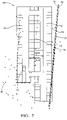
- the static landmarks represented by the elements are formed by grid-like fences. This means that, e.g., radar signals, may be partially reflected and partially passing through the fences leading to a plurality of detection points located in substantially different distances from the sensor system, e.g., in front, on, or behind a respective element (cf., e.g., Fig. 5 , detection point 48 relative to vehicle 10 and the element 43 in between).
- This is a particularly challenging application scenario which shows the merits of the invention well.
- the elements 24, 26, 28 show a geometrical correspondence with the groups of detection points 16, 18, and 20. In fact, it can be assumed that the elements 24, 26, 28 are causal for the groups of detection points 24, 26, 28, respectively. However, there is an angular displacement between the elements 24, 26, 28 and the detection points 16, 18, 20. This displacement corresponds with an inaccurate position of the vehicle 10 with respect to the world coordinate system 22.
- This inaccurate position can be denoted as a preliminary position estimated on the basis of, e.g., motion sensors of the vehicle 10 ("dead reckoning"), and a motion model can be used for estimating the preliminary position (also denoted as preliminary ego-pose).
- a matching procedure comprises first to evaluate the correspondence, i.e. the relationship between the elements 24, 26, 28 and the detection points 16, 18, 20. This is to find a transformation function which can be used to correct the inaccurate position.
- This transformation function can be a rigid transformation function including a translation and a rotation. This is to say that there can also be a translational displacement and not only an angular displacement between the detection points 16, 18, 20 and the elements 24, 26, 28 as shown in Fig. 2 .
- the step of actually compensating, i.e. correcting the preliminary position by means of the evaluated transformation function can be the second step of the matching procedure.
- a corresponding result is illustrated in Fig. 3 , in which the inaccurate position of the vehicle 10 from Fig. 2 has been corrected by means of transforming the vehicle coordinate system 12 with respect to the rigid transformation function (cf. vehicle coordinate system 12'). Accordingly, the transformed detection points 16', 18', 20' now approximately match with the elements 24, 26, 28.
- Fig. 4 gives a schematic overview of a particular matching procedure as introduced above.
- the term "navigation map” refers to a plurality of elements stored in a database, wherein a selection of elements within a range of the radar system ("radar scanners") can form a predefined map which is fed into a processing block 30.
- This block 30 also receives a plurality of detection points ("detections") acquired by means of the radar system.
- the nearest element is identified for each detection point.
- an assignment to the nearest element is carried out if one or more conditions are fulfilled.
- One condition is that the distance to the nearest element has to be below a predefined threshold. This is further illustrated in Fig.
- FIG. 5 which schematically shows a parking level 38 comprising a plurality of elements indicated as lines, e.g. the elements 40 and 42.
- the parking level 38 also comprises a plurality of parking spaces 44. These parking spaces 44 are preferably not coded by elements of the predefined map since they are not static landmarks in the sense of obstacles.
- the vehicle 10 has acquired a plurality of raw detection points 46 which form a cloud of detection points. Only a portion of the raw detection points 46 are assigned to the respective nearest element, namely the detection points 48 indicated as stars. These detection points 48 all have a distance to the nearest element below a threshold. These detection points 48 are assigned to the nearest element and form a subset of the raw detection points 46 used for further processing.
- Fig. 6 illustrates how the distance between a detection point 50 and the nearest element 40 can be evaluated.
- each detection point 50 can be orthogonally projected onto the nearest element 40, which gives an orthogonal projection 52.
- the distance between these two points is indicated as a dashed line the length of which is the Euclidean distance.
- this complementary element 56 is a regression line evaluated on the basis of those detection points which are nearest to the element 54, e.g., the detection points 64, 62 in Fig. 7 .
- the detection points 64, 62 in Fig. 7 For each of those detection points it is checked whether the distance to the complementary element 56 is below a threshold. This is equivalent to checking whether the position of the detection point is within a band between a first boundary 58 and a second boundary 60 with respect to the complementary element 56. If the detection point is within this band, the detection point is assigned to the element 54. In Fig. 7 , this is the case for the detection points 62 indicated as asterisks.
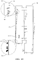
- Fig. 8 illustrates a situation similar to the one of Fig. 7 , wherein a complementary element 56' is evaluated for the detection points being nearest to the element 40, e.g., the detection points 62, 46. Eventually, this procedure is carried out for all detection points. The result is shown in Fig. 9 , wherein the detection points 62 indicated as asterisks form the filtered subset outputted from block 32 for further processing in block 34 (cf. Fig. 4 ).
- Further processing of the filtered detection points 62 may comprise evaluating weights for the detection points according to their assumed uncertainty. This corresponds to block 34 of Fig. 4 .
- each detection point is assumed to possess a certain, i.e. predefined measurement uncertainty which can be geometrically interpreted as an "area" around each detection point within which the true location represented by the detection point is assumed to be with high probability (i.e., the measurement uncertainty is modelled by a probability density function).
- This is effectively a probabilistic definition of the detection point, which may be represented as an individual covariance matrix for each detection point.
- This probabilistic approach is illustrated in Fig. 10 comprising two enlarged areas 66 and 70 adjacent to the element 40.
- an ellipse 68 is positioned around each of the detection points 64, thereby indicating an individual area of uncertainty associated with the respective detection point 64.
- Each of the ellipses 68 may be described by means of a covariance matrix.
- the uncertainty represented by the ellipses 68 may be parametric with respect to a measurement distance between the detection point and the radar sensor of the vehicle. Therefore, the uncertainty, i.e. the major axes of ellipses 68 may increase with the distance between the detection point and the associated radar sensor. This can be seen by comparing the ellipses 68 in the area 66 with the ellipses 72 for the detection points 74 in the enlarged area 70.
- the major axes of the ellipses 72 are much smaller due to the lower distance to the vehicle 10.
- the elliptic shape of the uncertainty is due to the fact that the uncertainty with respect to the distance (“first component”) is lower than the uncertainty with respect to an angle about the line of sight between the detection point and the associated sensor (“second component").
- a first weighting factor can be evaluated as illustrated in Fig. 11a .
- a circle 74 i.e. a first geometrical object is positioned centric around a given detection point 77.
- a quantity of detection points 76 sharing the circle 74 is determined by counting the number of detection points 76 within the circle 74.
- the quantity is 9 (excluding the centric detection point 77).
- the detection points 78 outside the circle 74 have no influence on the quantity.
- the quantity associated with a detection point 82 in Fig. 11b is zero because apart from the detection point 82 no other detection points are inside a circle 80 around the detection point 82. Therefore, the given detection point 77 of Fig. 11a has a larger weighting factor than the given detection point 82 of Fig. 11b because the given detection point 77 is considered to be less noisy due to the higher number of adjacent detection points.
- a second weighting factor can be evaluated by counting the number of detection points which are assigned to a respective element. This is to say that the elements of the predefined map, such as the elements 40 and 43 in Fig. 5 are treated as second geometrical objects, wherein each detection point assigned to a respective element has a second weighting factor corresponding to the number of detection points which are assigned to the same respective element. Therefore, if many detection points are assigned to a single element then all of these detection points have a comparably large second weighting factor.
- the first and second weighting factors can be multiplied.
- the resulting weights are illustrated in Fig. 12 by coding the weights by means of visual intensity. As shown by means of an intensity bar 86, the intensity values are between a minimum value 88 and a maximum value 90.
- the weights can be applied to the corresponding detection points by multiplying the inverse weights with the corresponding covariance matrices of the probabilistic model, as described in greater detail further above.
- the first and second weighting factors can also be combined in another way as multiplication or they can be used separately from each other.
- the application of the weights can be carried out within the scope of block 36, which refers to determining a rigid (body) transformation function for correcting the inaccurate ego-pose of the vehicle 10.
- the rigid body transformation can comprise parameters t x and t y (translation) and parameter ⁇ (rotation). These parameters can be found by minimizing the distances between the subset of detection points and the assigned elements. Transforming the inaccurate position with these parameters then gives the corrected position of the vehicle 10, which may be used for a wide range of applications, e.g. a valet parking application in the parking level 38, wherein the vehicle 10 automatically drives into a desired parking space 44 without requiring motor and steering control of the driver.
Description
- The invention relates to a method for determining the position of a vehicle. Vehicles known from the state of the art are capable of determining their current position on the basis of a least one sensor mounted on the vehicle. For example, many vehicles comprise a global-positioning system (GPS) from which the position of the vehicle can be inferred with a fair degree of accuracy. The determination of the position by means of a GPS requires a radio signal from the satellite space, which is, however, not always readily available. For example, the required GPS-signal can be very weak so that a relatively long time span is necessary in order to evaluate the position from the signal. Sometimes, the signal is too weak in order to securely determine the position. In other circumstances, there is even no signal available, for example, in fully or partially enclosed vicinities, such as road tunnels and buildings, in particular subterranean garages. Therefore, no position can be determined at all. As another problem, the accuracy of GPS is sometimes not sufficient, for example for autonomous-driving applications.
- Modern vehicles, for example upper-class cars, are already equipped with radar and/or lidar (light detection and ranging) systems. Corresponding measurements, i.e. scans, alone are, however, not suitable for determining the position with sufficient reliability and accuracy. The same problem occurs with one or more motion sensors mounted on the vehicle. In particular, most of such measurement methods, e.g., radar, are prone to produce outlier detection points which represent non-valid locations and can significantly corrupt the accuracy of a position determined on the basis of a plurality of detection points.
- Document
US 2016/0139255 A1 discloses a method for locating a vehicle from a reference map, which is merged from several radar measurements of the radar impulse responses at multiple positions. DocumentUS 9 199 643 B1 - It is an objective problem of the invention to provide an improved method for accurately and reliably determining the position of a vehicle.
- The objective problem is solved by the method according to claim 1.
- A method is adapted for determining the position of a vehicle equipped with a radar system, wherein the radar system includes at least one radar sensor adapted to receive radar signals emitted from at least one radar emitter of the radar system and reflected in a vicinity of the vehicle towards the radar sensor. The method comprises: acquiring at least one radar scan comprising a plurality of radar detection points, wherein each radar detection point is evaluated from a radar signal received at the radar sensor and representing a location in the vicinity of the vehicle; determining, from a database, a predefined map, wherein the map comprises at least one element representing a static landmark in the vicinity of the vehicle; matching at least a subset of the plurality of radar detection points of the at least one scan and the at least one element of the map; determining the position of the vehicle based on the matching.
- It has been found that radar measurements are in principle well suited for robust measurement of the vicinity of a vehicle. In particular, radar has advantages over optical measurements during sub-optimal weather conditions such as rain and fog. However, as pointed out above, determining the position of the vehicle on the basis of radar scans can has shortcomings with regard to accuracy and reliability. This is because a radar scan usually comprises a plethora of raw radar detection points from which only a portion represent valid measurements, e.g., due to noise. Therefore, it is found that some sort of processing, i.e. filtering, of the raw detection points is usually required. However, standard approaches of processing are not always sufficient in order to reliably and accurately determine the position of a vehicle. Although radar systems can provide many measurements per time span, there is a limitation to distance and angle information per time instant relative to the underlying vehicle. Therefore, tracking the position of the vehicle over time based on an initialization position and subsequent radar scans is not sufficient for accurate determination of the position of the vehicle, which can also be denoted as ego-pose estimation. In this regard, it is proposed to make use of some ground-truth data, which is configured to represent the vicinity of the vehicle. This ground-truth data is provided in the form of a database, which comprises map data that represents a geo-structural model. The map data describes the vicinity of a desired driving area, which preferably comprises characteristic objects, i.e. static landmarks limiting a desired driving area of a vehicle. Examples for such landmarks are walls, fences but also substantial pavement edges and bigger plants, e.g., trees and the like. Although such objects will usually limit a driving area, the map data is not limited thereto. This is to say that the map data can also comprise landmarks which are not directly relevant for defining an allowable driving space. In principle, the map data can comprise descriptions of those objects which will be sensed by a radar system in the vicinity thereof.
- The map data stored in the database comprises representations of static landmarks in form of so-called elements. These elements are of mathematical nature and are simplified and parametric models of the objects which they describe, as will be explained in greater detail below. Due to the mathematical or "modelled" nature of the elements they can also be denoted as native elements, i.e. elements which are defined from scratch. In particular, each of the elements comprises information about its global position, i.e. in a world coordinate system. In contrast, detection points acquired by means of a radar system of a vehicle typically only comprise information about a relative position, i.e. the detection points are typically described in a coordinate system of the vehicle which can be defined by means of a coordinate system of the sensor system. This means that the detection points, which can be measured with respect to a sensor coordinate system, can be transformed into a coordinate system of the vehicle.
- The map data in the database can comprise map data which captures a desired driving area, for example all valid driving areas in a given country or a group of different countries. From this map data a predefined map is determined, wherein the predefined map can be limited to a current vicinity of the vehicle. This current vicinity can be limited to a specified range of the radar system so that the predefined map includes only those elements within the range, i.e., those objects which are potentially hit by radar signals emitted from the radar system. Therefore, the step of determining the predefined map comprises identifying a portion of the map which corresponds to a current "view" of the radar system, thereby providing a geo-structural description of the local vicinity of the vehicle at a given time instant. The predefined map can be determined on the basis of a position information derived from a current GPS-signal received at the vehicle. If such a signal is currently not available the last GPS-signal or another inaccurate position estimation may be used.
- Each of the plurality of elements of the predefined map represents a static landmark in the vicinity of the vehicle. Therefore, a given element is associated with a maximum likelihood of being causal for the location represented by at least some detection points. The predefined map can be navigation map, in particular a navigation map from a publicly available database, e.g. open-street map. The predefined map can be derived from a global database on the basis of a given position of the vehicle, e.g. from a global position system of the vehicle, as indicated further above. The static landmarks can be static objects, e.g. walls of buildings or other barriers for the vehicle which form objects detectable by the sensor system of the vehicle.
- The predefined map, i.e. the at least one element thereof, is then matched with at least a subset of the plurality of radar detection points. The plurality of radar detection points are acquired by means of one or more scans, wherein in the latter case, the scans are preferably successive scans. The radar detection points can be raw detection points or filtered by means of a preprocessing method. As such, the subset of the plurality of detection points used for the matching can be a selection of the raw detection points. Preferably, the detection points correspond to a substantially common time instant, which may also be a short time span.
- The term "matching" can be understood in the sense of evaluating a correspondence between the radar detection points and the elements. In principle, since each radar detection point has an uncertainty with respect to the location it represents, the elements - as a ground truth - can be used to find a location with an increased certainty (i.e., the elements are used to reduce the uncertainty with respect to detection points). This is because the elements represent static landmarks which should be detected from the radar system, i.e., at least a substantial portion of the radar detection points should lie on the elements within the range of the radar system. If a respective detection point does not lie on an element, this can be an indication that the radar detection point is subject to an error. Therefore, the elements can be used to perform a correction of the radar detection points, in particular of those detection points nearby a respective element. This will be explained in greater detail further below.
- The position of the vehicle is determined on the basis of the matching. This is to say that the correspondence between the radar detection points and the elements is exploited for the determination of the position. In general, the position can be determined from any appropriate sensor measurement or a combination thereof. The combination proposed here, namely radar detection points and elements, can be sufficient to determine the position. The matching allows to increase the accuracy of the position determination. Beyond radar detection points and the elements of the predefined map, additional sensor measurements can be used for determining the position, e.g., from one or more motion sensors of the vehicle.
- Although the methods described herein use a radar system of a vehicle, it is understood that the methods may also be adopted using detection points of a lidar system instead of a radar system. Combinations of radar and lidar detection points may also be possible.
- Preferably, the position of the vehicle comprises coordinates representing a location of the vehicle with respect to a coordinate system. Furthermore, the position can comprise an angle of the vehicle representing a heading, i.e. an orientation of the vehicle with respect to a reference heading.
- In one embodiment, the method can be implemented in a vehicle in order to provide one or more autonomous-driving applications requiring accurate information about a current position of the vehicle. One such application is valet parking in a parking level, wherein the vehicle automatically drives into a desired parking space without requiring motor and steering control of the driver. This is to say that the driving behaviour of the vehicle (i.e. "the vehicle") is controlled or modified with respect to the determined position of the vehicle.
- Advantageous embodiments of the invention are specified in the dependent claims, the description and the drawings.
- According to a preferred embodiment, the method does not comprise using data from a space-based radio-navigation system, in particular a global positioning system, of the vehicle. In this connection, the elements preferably comprise positional data which is used to determine the position of the vehicle. In particular, the elements provide information about the absolute position of the landmarks in the vicinity of the vehicle and the radar detection points provide information about the position of the vehicle relative to the elements. In this way, the position of the vehicle can be determined with greater accuracy and also with increased reliability without the requirement of having a sufficient connection to a GPS-signal.
- Having regard to the predefined map, the at least one element of the map comprises an extended geometrical object, in particular a line or a surface, preferably a straight line or a plane. Each element can represent exactly one static landmark. Since the elements correspond to static landmarks modelled for a map, the elements can also de denoted as native elements. It has turned out that in most cases a straight line is sufficient in order to describe a static landmark for the purpose of the methods described herein. A straight line has the advantage that it can be described with a small number of parameters, for example, the coordinates of a starting point and an end point of the line. Preferably, a straight line is described as a mathematical function, i.e., f(x)=ax+b, possibly limited by a starting point and an end point. This is to say that a straight line is described by a mathematical function only, with optional limitation parameters specifying and a starting and/or an end point of the line.
- Moreover, using straight lines has advantages with regard to a low computational load associated with the processing of the method, in particular with regard to the matching ("point-to-line matching"). A line can be used to describe geo-structural limitations in two dimensions, which can be advantageous for efficient processing. Three-dimensional limitations may be explicitly described by surfaces.
- It is understood that a landmark can be described by exactly one element (e.g., a line) or more than one element. Each element can be formed by a straight line but other types of lines are also possible, for example curved lines. A landmark can also be described by several sections forming elements.
- As mentioned above, the accuracy of the position determined by the method can be improved by a (pre-) filtering, i.e. processing of the raw radar detection points (the detection points which are evaluated by the radar system without any weighting but possibly including a prior selection of detection points being evaluated from radar signals having sufficient signal strength and representing static locations with respect to a Doppler-shift information of the radar system). In this regard, the method can comprise determining, by means of a prefiltering of the plurality of radar detection points, the subset of the plurality of radar detection points to be matched, wherein the prefiltering comprises conducting at least or exactly two steps for each radar detection point of the plurality of radar detection points. These steps are (i) identifying, from the at least one element of the map, a respective element having a minimum distance to a respective one of the plurality of radar detection points, (ii) assigning the respective element so identified to the respective one of the plurality of radar detection points if the distance is below a predefined threshold, wherein the subset of the plurality of radar detection points includes all radar detection points from the plurality of radar detection points to which an element has been assigned. With regard to step (i), preferably the Euclidian, i.e. orthogonal distance metric is used. In this way, the nearest element is identified for each radar detection point. In step (ii), all radar detection points which are "too far away" from the nearest element are filtered away, i.e. are discarded for the matching. In turn, only those radar detection points within a threshold or "tolerance" band survive the prefiltering and are used for the matching and the subsequent determination of the position. In this way, the accuracy and reliability of the method is further increased because those detection points which are a-priori not likely to represent a valid detection point of a static landmark (i.e. element) are discarded. A further advantage is the assignment of a respective radar detection point to a "dedicated" element. Although a given radar detection point can be assigned to more than one element, e.g., when several elements have a substantially equal distance to a respective detection point, the assignment to a single detection point (forming pairs of respective radar detection points and assigned elements) has shown to provide the desired increase of accuracy while also reducing the computational load.
- The prefiltering can be regarded as a plausibility constraint because the physical basis of each detection point (located on a static landmark) should not be too far away from the measured location. Otherwise, a detection point is preferably discarded, e.g., for the determination of the position of the vehicle. In this way, it is also avoided that an error is accumulated during successive estimations of the position of the vehicle.
- As an alternative to the prefiltering described above or additionally, the method can further comprise determining, by means of a prefiltering of the plurality of detection points, the subset of the plurality of detection points, wherein the prefiltering comprises, for each detection point of the plurality of detection points, (i) identifying, from the plurality of elements of the predefined map, an element having a minimum distance to the detection point, (ii) assigning the detection point to the identified element, (iii) assigning the detection point to the subset of the plurality of detection points if the distance between the detection point and a complementary element is below a second predefined threshold, wherein the complementary element is evaluated on the basis of the detection points being assigned to the identified element, wherein the number of detection points being assigned to the identified element and to the complementary element is maximized. The complementary element is preferably a straight line being evaluated by means of simple linear regression on the basis of a set of randomly chosen detections points which are assigned to a respective element of the predefined map. Preferably, the set of randomly chosen detection points is only a portion of the overall number of detection points assigned to the identified element. The step of randomly choosing detection points can be repeated a number of times. Afterwards, the set which leads to the maximum number of detection points being assigned to both the identified element (of the predefined map) and the complementary element (for the respective random set) is chosen as the subset of detection points "surviving" the prefiltering. The general approach is sometimes also referred to as random sample consensus (RANSAC).
- According to another embodiment, the matching comprises determining a rigid transformation function (also denoted as rigid body transformation function) by minimizing distances between transformed radar detection points and the one or more elements assigned to the plurality of radar detection points, wherein the transformed radar detection points represent the subset of the plurality of radar detection points transformed by means of the rigid transformation function. Preferably, the rigid transformation function is determined by minimizing the sum of the Euclidian distances between each transformed radar detection point and the element assigned to this detection point. In particular, determining the rigid transformation function can comprise minimizing the expression

- P represents the subset of m radar detection points,
- R represents a rotation,
- t represents a translation,
- pi represents the i-th radar detection point of P,
- bi represents the orthogonal distance to the element assigned to the
- i-th radar detection point of P,
-

- The rigid transformation function can be interpreted as a transformation of the coordinate system used for describing (the locations of) the detection points. This is that all radar detection points are transformed in the same way. In this regard, the error function F represents the sum of the squared Euclidian (i.e., orthogonal) distances between the transformed detection points and the assigned elements. Each detection point pi and corresponding normal vector

- According to another embodiment, determining the rigid transformation function involves a probabilistic model, wherein at least one parameter of the probabilistic model represents an expected variance of at least a respective one of the plurality of radar detection points, wherein the expected variance is non-constant. In this way, the uncertainty of the measurement of the radar detection points can be taken into account, thereby further increasing the accuracy of the determination of the position of the vehicle. The expected variance can be expressed by a covariance matrix, which can be individual for each detection point. The covariance matrix can determined by a parametric function such as the distance between the sensor system and the location represented by the detection point.
- The probabilistic model can be of the type of a so-called Gauss-Helmert-Model, which is described in greater detail, e.g., in "K.-R. Koch: Parameterschaetzung und Hypothesentests in linearen Modellen. Ehemals Ferd. Dümmlers Verlag, Bonn, 2004". The probabilistic model can be the Gauss-Helmert-Model described therein. It is understood that this model can be used in the context of the applications described herein.
- In a particular embodiment, the expected variance of the radar detection point can comprise a first component and a second component, wherein the first component represents the expected variance with respect to a distance between the location in the vicinity of the vehicle represented by the radar detection point and the radar sensor at which the radar signal (from which the radar detection point is evaluated) is received, wherein the second component represents the expected variance with respect to an angle identifying a direction of the location in the vicinity of the vehicle represented by the radar detection point relative to the radar sensor at which the radar signal (from which the radar detection point is evaluated) is received, and wherein the first component is smaller than the second component. In other words, the expected variance has a distance and an angular component, wherein the angular component has a greater uncertainty than the distance component. Therefore, the major axis of the ellipse, which represents the expected variance, is getting larger when the distance gets larger (the major axis is transverse to the line of sight). This modelling adds in increasing the accuracy of the determination of the vehicle's position.
- As an example of minimizing the above error function F, consider again the m detection points, each having coordinates in directions x and y:

- A rotation and a translation can be described by:

- For linearizing the error function F, a Taylor series expansion can be adopted with split-ups of the detection points and the optimum parameter


- is the Taylor point and
V - is an improvement term. The minimization of F as can be solved as


- This "global covariance matrix" for all detections, e.g. of one or more scans, can be weighted element-wise with weights


- A weight can include a first weighting factor and/or a second weighting factor, wherein the first weighting factor represents a quantity of detection points in a first group of detection points and the second weighting factor represents a quantity of detection points in a second group of detection points. Furthermore, the detection points of the first group share a first geometrical object and the detection points of the second group share a second geometrical object. The second geometrical object is determined from a predefined map representing the vicinity of the vehicle, and the first geometrical object is determined independently from the predefined map.
- A weight can be evaluated for a given detection point pi (with i = 1, 2,...,m) comprising multiplying a first weighting factor and a second weighting factor, wherein the first weighting factor can be defined as

i | is the quantity of the first group, and γ is a free parameter, wherein the second weighting factor can be defined as
i |, |Nr | from the maximum quantities Mp , Mmap and dividing by Mp , Mmap in the exponential terms of the first and second weighting factors, respectively, is one way of normalizing the determined quantities to the maximum quantity. As the skilled person understands the above expressions of the weighting factors are only one exemplary formulation and other, i.e. derived expressions may be used to achieve the same desired weighting behaviour. An inverse representation of the weight can be given by inverting the two weighting factors; that is to change the minus signs of the exponential terms into plus signs. The inverted weighting factors may be applied to the covariance matrix as described above. Scaling the covariance matrix inversely with respect to the weight can have the effect of increasing the uncertainty the less weight should be given to the detection point. Therefore, the increased uncertainty can be taken into account during determination of the position, thereby reducing the impact of the weighted detection point on the result. - The method preferably further comprises determining, from a motion model of the vehicle, a preliminary position of the vehicle, wherein determining the position of the vehicle comprises transforming the preliminary position by means of the rigid transformation function. The motion model can be a model which describes the trajectory of the vehicle over time. The model can be initialized with some value and is then periodically updated based on motion measurements of the vehicle. In this regard, the motion model is preferably determined on the basis of at least one measurement from at least one motion sensor of the vehicle and/or on the basis of at least some of the plurality of radar detection points. The combination of measurements from a motion sensor and a radar system can further enhance the accuracy of the method.
- The measurement from the at least one motion sensor can comprise a velocity and/or a yaw rate of the vehicle, wherein the vehicle preferably comprises corresponding sensor facilities. This is also known as "dead-reckoning" measurements. Preferably, the velocity and/or the yaw rate of the vehicle is determined on the basis of wheel-speed-sensor (wheel rotation per time span) measurements and/or yaw-rate-sensor measurements, and/or on the basis of the radar detection points. Dead-reckoning measurements taken alone have been found to provide inaccurate estimations of the vehicle position under certain conditions, e.g., during strong steering maneuvres. For this reason, the estimation based on dead-reckoning can represent a preliminary estimation of the vehicle's position. The rigid transformation function can be applied to the preliminary position in order to arrive at a final position which has greater accuracy than the preliminary position:

- Pdr
is the preliminary, i.e. inaccurate position of the vehicle and - Psm
is the corrected position which may be denoted as "scan-matching position", and wherein the rigid transformation function is determined by the optimized parameter vector
- According to another embodiment, the subset or all of the plurality of radar detection points used for matching includes radar detection points from a plurality of successive radar scans of the radar system, in particular 1 to 20 scans, preferably 10 scans, wherein the scan rate is between 10 to 40 Hz, preferably 20 Hz.
- The invention further relates to a vehicle equipped with a radar system, wherein the radar system includes at least one radar sensor adapted to receive radar signals emitted from at least one radar emitter of the radar system and reflected in a vicinity of the vehicle towards the radar sensor, and a control and processing unit, wherein the control and processing unit is configured to carry out the method according to at least one of the preceding embodiments. The control and processing unit may comprise a storage device in which instructions implementing embodiments of the described methods are stored. Preferably, the method can be carried out without a mobile connection to a central server or the like. Therefore, the storage device can also comprise a database including data for determining a predefined map representing the vicinity of the vehicle. However, as the skilled person understands, use of a mobile connection can be made for updating or incorporating data while carrying out the method.
- The invention is described further in the following by means of exemplary embodiments shown in the drawings in which
- Fig. 1
- is a schematic illustration of a vehicle and a plurality of detection points in a vehicle coordinate system;
- Fig. 2
- is the schematic illustration of
Fig. 1 transformed into a world coordinate system and additionally showing a plurality of elements of a predefined map; - Fig. 3
- is the schematic illustration of
Fig. 2 , wherein the vehicle and the detection points are transformed by means of a rigid body transformation function; - Fig. 4
- is a schematic overview illustrating a method for determining the position of a vehicle equipped with a radar system and motion sensors;
- Fig. 5
- is a schematic illustration of a predefined map representing a parking level, wherein the illustration further comprises a vehicle and a plurality of detection points acquired by means of a radar system of the vehicle;
- Fig. 6
- is a schematic illustration of a predefined map representing a parking level, wherein the illustration further comprises a vehicle and a plurality of detection points acquired by means of a radar system of the vehicle, wherein an orthogonal projection of the detection points onto the nearest element of the predefined map is illustrated;
- Fig. 7
- illustrates a prefiltering of detection points for a portion of detection points assigned to the right most element of the predefined map;
- Fig. 8
- illustrates a prefiltering of detection points for a portion of detection points assigned to the left most element of the predefined map;
- Fig. 9
- illustrates a prefiltering of detection points for a plurality of detection points assigned to nearest elements of the predefined map, respectively;
- Fig. 10
- illustrates an uncertainty associated with detection points;
- Fig. 11a
- illustrates a plurality of detections points and a circle centred with respect to one of the detection points, wherein the portion of detection points inside the circle form a group of detection points;
- Fig. 11b
- illustrates a circle centred with respect to one detection point, wherein no other detection points are inside the circle;
- Fig. 12
- illustrates evaluated weights for a plurality of detection points.
- In the figures, the same or corresponding elements are indicated with the same reference signs.
-
Figs. 1 to 3 provide a basic illustration of a matching procedure in the context of the methods described herein. InFig. 1 , a schematic of avehicle 10 is positioned in the origin of a coordinatesystem 12 of thevehicle 10. The vehicle coordinatesystem 12 is indicated as a Cartesian coordinate system with axes x and y in orthogonal relation to each other, wherein the vehicle's heading is aligned with the x-axis of the coordinatesystem 12. - The
vehicle 10 has a radar system comprising a total of fourpairs 14 of radar sensors and radar emitters, which are positioned in each of the corners of thevehicle 10. Therefore, thevehicle 10 is configured to "look" within an angle range of 360 degrees around the vicinity of thevehicle 10. It is understood that thevehicle 10 can have a different number of radar sensors and emitters which also can be positioned in a different configuration than shown inFig. 1 . - In
Fig. 1 , a plurality of detection points are arranged ingroups vehicle 10, wherein each detection point is indicated with a star and illustrates a location in the vicinity of thevehicle 10. The detection points are acquired by means of the radar system in one or more scans. -
Fig. 2 corresponds toFig. 1 , wherein thevehicle 10 and the vehicle coordinatesystem 12 are shown with respect to a world coordinatesystem 22 which is also a Cartesian coordinate system with axes x and y and which can be a coordinate system of the predefined map. However, the detection points 16, 18, 20 are shown with respect to the vehicle coordinatesystem 12. Additionally,Fig. 2 shows a plurality ofelements system 22. Theseelements vehicle 10. In particular, theelements elements elements vehicle 10 and that theelements Fig. 5 ,detection point 48 relative tovehicle 10 and theelement 43 in between). This is a particularly challenging application scenario which shows the merits of the invention well. - As can readily be seen from
Fig. 2 , theelements elements elements vehicle 10 with respect to the world coordinatesystem 22. This inaccurate position can be denoted as a preliminary position estimated on the basis of, e.g., motion sensors of the vehicle 10 ("dead reckoning"), and a motion model can be used for estimating the preliminary position (also denoted as preliminary ego-pose). - Having regard to compensating the mentioned angular displacement, a matching procedure comprises first to evaluate the correspondence, i.e. the relationship between the
elements elements Fig. 2 . The step of actually compensating, i.e. correcting the preliminary position by means of the evaluated transformation function can be the second step of the matching procedure. A corresponding result is illustrated inFig. 3 , in which the inaccurate position of thevehicle 10 fromFig. 2 has been corrected by means of transforming the vehicle coordinatesystem 12 with respect to the rigid transformation function (cf. vehicle coordinate system 12'). Accordingly, the transformed detection points 16', 18', 20' now approximately match with theelements -
Fig. 4 gives a schematic overview of a particular matching procedure as introduced above. The term "navigation map" refers to a plurality of elements stored in a database, wherein a selection of elements within a range of the radar system ("radar scanners") can form a predefined map which is fed into aprocessing block 30. Thisblock 30 also receives a plurality of detection points ("detections") acquired by means of the radar system. Inblock 30, the nearest element is identified for each detection point. Inblock 32, an assignment to the nearest element is carried out if one or more conditions are fulfilled. One condition is that the distance to the nearest element has to be below a predefined threshold. This is further illustrated inFig. 5 which schematically shows aparking level 38 comprising a plurality of elements indicated as lines, e.g. theelements parking level 38 also comprises a plurality ofparking spaces 44. Theseparking spaces 44 are preferably not coded by elements of the predefined map since they are not static landmarks in the sense of obstacles. Thevehicle 10 has acquired a plurality of raw detection points 46 which form a cloud of detection points. Only a portion of the raw detection points 46 are assigned to the respective nearest element, namely the detection points 48 indicated as stars. These detection points 48 all have a distance to the nearest element below a threshold. These detection points 48 are assigned to the nearest element and form a subset of the raw detection points 46 used for further processing. -
Fig. 6 illustrates how the distance between adetection point 50 and thenearest element 40 can be evaluated. In a mathematical sense, eachdetection point 50 can be orthogonally projected onto thenearest element 40, which gives anorthogonal projection 52. The distance between these two points is indicated as a dashed line the length of which is the Euclidean distance. - As an alternative to assigning detection points to the nearest element if the distance between them is below a threshold (cf.
block 32 inFig. 4 ), it is also possible to allow an assignment if the distance between the respective detection point and a complementary element 56 (cf.Fig. 7 ) is below a threshold. InFig. 7 , thiscomplementary element 56 is a regression line evaluated on the basis of those detection points which are nearest to theelement 54, e.g., the detection points 64, 62 inFig. 7 . For each of those detection points it is checked whether the distance to thecomplementary element 56 is below a threshold. This is equivalent to checking whether the position of the detection point is within a band between afirst boundary 58 and asecond boundary 60 with respect to thecomplementary element 56. If the detection point is within this band, the detection point is assigned to theelement 54. InFig. 7 , this is the case for the detection points 62 indicated as asterisks. -
Fig. 8 illustrates a situation similar to the one ofFig. 7 , wherein a complementary element 56' is evaluated for the detection points being nearest to theelement 40, e.g., the detection points 62, 46. Eventually, this procedure is carried out for all detection points. The result is shown inFig. 9 , wherein the detection points 62 indicated as asterisks form the filtered subset outputted fromblock 32 for further processing in block 34 (cf.Fig. 4 ). - Further processing of the filtered detection points 62 may comprise evaluating weights for the detection points according to their assumed uncertainty. This corresponds to block 34 of
Fig. 4 . A priori, each detection point is assumed to possess a certain, i.e. predefined measurement uncertainty which can be geometrically interpreted as an "area" around each detection point within which the true location represented by the detection point is assumed to be with high probability (i.e., the measurement uncertainty is modelled by a probability density function). This is effectively a probabilistic definition of the detection point, which may be represented as an individual covariance matrix for each detection point. This probabilistic approach is illustrated inFig. 10 comprising twoenlarged areas 66 and 70 adjacent to theelement 40. In the enlarged area 66, anellipse 68 is positioned around each of the detection points 64, thereby indicating an individual area of uncertainty associated with therespective detection point 64. Each of theellipses 68 may be described by means of a covariance matrix. The uncertainty represented by theellipses 68 may be parametric with respect to a measurement distance between the detection point and the radar sensor of the vehicle. Therefore, the uncertainty, i.e. the major axes ofellipses 68 may increase with the distance between the detection point and the associated radar sensor. This can be seen by comparing theellipses 68 in the area 66 with theellipses 72 for the detection points 74 in theenlarged area 70. In the latter case, the major axes of theellipses 72 are much smaller due to the lower distance to thevehicle 10. The elliptic shape of the uncertainty is due to the fact that the uncertainty with respect to the distance ("first component") is lower than the uncertainty with respect to an angle about the line of sight between the detection point and the associated sensor ("second component"). - From the perspective of measurement accuracy, usually not all detection points will have an equal accuracy, i.e. some detection points are more noisy than others. In this context, weights can be evaluated which represent an assumed degree of noisiness, i.e. uncertainty, for each detection point. These weights can then be used to modify a predefined uncertainty for each detection point in an individual way, as has been described further above. For a given detection point, a first weighting factor can be evaluated as illustrated in
Fig. 11a . Acircle 74, i.e. a first geometrical object is positioned centric around a givendetection point 77. A quantity of detection points 76 sharing thecircle 74 is determined by counting the number of detection points 76 within thecircle 74. InFig. 11a , the quantity is 9 (excluding the centric detection point 77). The detection points 78 outside thecircle 74 have no influence on the quantity. In a comparison, the quantity associated with adetection point 82 inFig. 11b is zero because apart from thedetection point 82 no other detection points are inside acircle 80 around thedetection point 82. Therefore, the givendetection point 77 ofFig. 11a has a larger weighting factor than the givendetection point 82 ofFig. 11b because the givendetection point 77 is considered to be less noisy due to the higher number of adjacent detection points. As the skilled person understands, it is also possible to add the givendetections - A second weighting factor can be evaluated by counting the number of detection points which are assigned to a respective element. This is to say that the elements of the predefined map, such as the
elements Fig. 5 are treated as second geometrical objects, wherein each detection point assigned to a respective element has a second weighting factor corresponding to the number of detection points which are assigned to the same respective element. Therefore, if many detection points are assigned to a single element then all of these detection points have a comparably large second weighting factor. - As described in detail further above, the first and second weighting factors can be multiplied. The resulting weights are illustrated in
Fig. 12 by coding the weights by means of visual intensity. As shown by means of anintensity bar 86, the intensity values are between aminimum value 88 and a maximum value 90. The weights can be applied to the corresponding detection points by multiplying the inverse weights with the corresponding covariance matrices of the probabilistic model, as described in greater detail further above. The first and second weighting factors can also be combined in another way as multiplication or they can be used separately from each other. - Turning back to
Fig. 4 , the application of the weights can be carried out within the scope ofblock 36, which refers to determining a rigid (body) transformation function for correcting the inaccurate ego-pose of thevehicle 10. The rigid body transformation can comprise parameters tx and ty (translation) and parameter φ (rotation). These parameters can be found by minimizing the distances between the subset of detection points and the assigned elements. Transforming the inaccurate position with these parameters then gives the corrected position of thevehicle 10, which may be used for a wide range of applications, e.g. a valet parking application in theparking level 38, wherein thevehicle 10 automatically drives into a desiredparking space 44 without requiring motor and steering control of the driver. -
- 10
- vehicle
- 12, 12'
- vehicle coordinate system
- 14
- radar sensor and emitter
- 16 18, 20
- detection point
- 16', 18', 20'
- detection point
- 22
- world coordinate system
- 24, 26, 28
- element
- 30
- identification of nearest element
- 32
- assignment to nearest element
- 34
- evaluate weights
- 36
- matching
- 38
- parking level
- 40, 42, 43
- element
- 46
- detection point
- 48
- filtered detection point
- 50
- detection point
- 52
- orthogonal projection
- 54
- element
- 56
- complementary element
- 58
- first boundary
- 60
- second boundary
- 62
- filtered detection point
- 64
- detection point
- 66
- enlarged area
- 68
- ellipse
- 70
- enlarged area
- 72
- ellipse
- 74
- circle
- 76
- inside detection point
- 78
- outside detection point
- 80
- circle
- 82
- detection point
- 84
- filtered detection point
- 86
- intensity bar
- 88
- minimum intensity
- 90
- maximum intensity
Claims (14)
- A method for determining the position of a vehicle (10) equipped with a radar system (14), wherein the radar system includes at least one radar sensor adapted to receive radar signals emitted from at least one radar emitter of the radar system (14) and reflected in a vicinity of the vehicle (10) towards the radar sensor,
wherein the method comprises:- acquiring at least one radar scan comprising a plurality of radar detection points (16), wherein each radar detection point is evaluated from a radar signal received at the radar sensor and representing a location in the vicinity of the vehicle (10) in a vehicle coordinate system,- providing ground-truth data in the form of a database comprising map data representing a geo-structural model,- determining, from the database, a predefined map, wherein the map comprises at least one element (24) representing a static landmark in the vicinity of the vehicle (10), wherein the at least one element (24) of the map is a simplified and parametric model of the static landmark and comprises information about its global position in a world coordinate system,- matching at least a subset of the plurality of radar detection points (16) of the at least one scan and the at least one element (24) of the map,- determining the position of the vehicle (10) based on the matching,wherein the at least one element (24) of the map comprises an extended geometrical object. - The method according to claim 1,
wherein the method does not comprise using data from a space-based radio-navigation system, in particular a global positioning system, of the vehicle (10). - The method according to claim 1 or 2,
wherein the geometrical object is a line or a surface, preferably a straight line or a plane. - The method according to at least one of the preceding claims,further comprising determining, by means of a prefiltering (30, 32) of the plurality of radar detection points (46), the subset (48) of the plurality of radar detection points to be matched,wherein the prefiltering (30, 32) comprises, for each radar detection point of the plurality of radar detection points (46),identifying, from the at least one element of the map, a respective element (40) having a minimum distance to a respective one (46) of the plurality of radar detection points,assigning the respective element so identified to the respective one of the plurality of radar detection points if the distance is below a predefined threshold,wherein the subset of the plurality of radar detection points includes all radar detection points (48) from the plurality of radar detection points to which an element has been assigned.
- The method according to at least one of the preceding claims,
wherein the matching comprises determining a rigid transformation function by minimizing distances between transformed radar detection points and the at least one element assigned to the plurality of radar detection points, wherein the transformed radar detection points represent the subset of the plurality of radar detection points transformed by means of the rigid transformation function. - The method according to claim 5,
wherein determining the rigid transformation function comprises minimizing P represents the subset of m radar detection points,R represents a rotation,t represents a translation,pi represents the i-th radar detection point of P,bi represents the orthogonal distance to the element assigned to the i-th radar detection point of P,
- The method according to claim 5 or 6,
wherein determining the rigid transformation function comprises a probabilistic model, wherein at least one parameter of the probabilistic model represents an expected variance (68) of a respective one (64) of the plurality of radar detection points, wherein the expected variance is non-constant. - The method according to claim 7,wherein, for a respective radar detection point, the expected variance of the radar detection point comprises a first component and a second component,wherein the first component represents the expected variance with respect to a distance between the location in the vicinity of the vehicle (10) represented by the radar detection point and the at least one radar sensor, wherein the second component represents the expected variance with respect to an angle identifying a direction of the location in the vicinity of the vehicle (10) represented by the radar detection point relative to the at least one radar sensor, andwherein the first component is smaller than the second component.
- The method according to at least one of claims 5 to 8,wherein the method further comprisesdetermining, from a motion model of the vehicle (10), a preliminary position of the vehicle (10),wherein determining the position of the vehicle (10) comprises transforming the preliminary position by means of the rigid transformation function.
- The method according to claim 9,
wherein the motion model is determined on the basis of at least one measurement from at least one motion sensor of the vehicle (10) and/or on the basis of at least some of the plurality of radar detection points. - The method according to claim 10,
wherein the measurement from the at least one motion sensor comprises a velocity and/or a yaw rate of the vehicle (10). - The method according to at least one of the preceding claims,
wherein the position of the vehicle (10) comprises coordinates representing a location and an orientation of the vehicle (10). - The method according to at least one of the preceding claims,
wherein the subset of the plurality of radar detection points (46) includes radar detection points from a plurality of successive radar scans of the radar system (14), in particular 1 to 20 scans, preferably 10 scans, wherein the scan rate is between 10 to 40 Hz, preferably 20 Hz. - A vehicle (10) equipped with a radar system (14), wherein the radar system (14) includes at least one radar sensor adapted to receive radar signals emitted from at least one radar emitter of the radar system (14) and reflected in a vicinity of the vehicle (10) towards the radar sensor, and a control and processing unit, wherein the control and processing unit is configured to carry out the method according to at least one of the preceding claims.
Priority Applications (3)
| Application Number | Priority Date | Filing Date | Title |
|---|---|---|---|
| EP18153439.7A EP3517996B1 (en) | 2018-01-25 | 2018-01-25 | Method for determining the position of a vehicle |
| US16/241,404 US11500083B2 (en) | 2018-01-25 | 2019-01-07 | Method for determining the position of a vehicle |
| CN201910063028.2A CN110082753B (en) | 2018-01-25 | 2019-01-23 | Method for determining the position of a vehicle |
Applications Claiming Priority (1)
| Application Number | Priority Date | Filing Date | Title |
|---|---|---|---|
| EP18153439.7A EP3517996B1 (en) | 2018-01-25 | 2018-01-25 | Method for determining the position of a vehicle |
Publications (2)
| Publication Number | Publication Date |
|---|---|
| EP3517996A1 EP3517996A1 (en) | 2019-07-31 |
| EP3517996B1 true EP3517996B1 (en) | 2022-09-07 |
Family
ID=61027560
Family Applications (1)
| Application Number | Title | Priority Date | Filing Date |
|---|---|---|---|
| EP18153439.7A Active EP3517996B1 (en) | 2018-01-25 | 2018-01-25 | Method for determining the position of a vehicle |
Country Status (3)
| Country | Link |
|---|---|
| US (1) | US11500083B2 (en) |
| EP (1) | EP3517996B1 (en) |
| CN (1) | CN110082753B (en) |
Families Citing this family (12)
| Publication number | Priority date | Publication date | Assignee | Title |
|---|---|---|---|---|
| EP3517996B1 (en) | 2018-01-25 | 2022-09-07 | Aptiv Technologies Limited | Method for determining the position of a vehicle |
| EP3518001B1 (en) | 2018-01-25 | 2020-09-16 | Aptiv Technologies Limited | Method for increasing the reliability of determining the position of a vehicle on the basis of a plurality of detection points |
| US20220221581A1 (en) * | 2019-05-21 | 2022-07-14 | Nippon Telegraph And Telephone Corporation | Depth estimation device, depth estimation method, and depth estimation program |
| EP3819663A1 (en) * | 2019-11-07 | 2021-05-12 | Aptiv Technologies Limited | Method for determining a position of a vehicle |
| EP3828587A1 (en) * | 2019-11-29 | 2021-06-02 | Aptiv Technologies Limited | Method for determining the position of a vehicle |
| EP3851870A1 (en) * | 2020-01-14 | 2021-07-21 | Aptiv Technologies Limited | Method for determining position data and/or motion data of a vehicle |
| CN111192478B (en) * | 2020-04-10 | 2020-07-21 | 南京楚航科技有限公司 | Road parking space state identification method based on millimeter wave radar |
| CN114252883B (en) * | 2020-09-24 | 2022-08-23 | 北京万集科技股份有限公司 | Target detection method, apparatus, computer device and medium |
| CN112213725B (en) * | 2020-09-28 | 2022-10-25 | 森思泰克河北科技有限公司 | Multipath false alarm suppression method and device for vehicle-mounted radar and terminal equipment |
| CN112986971B (en) * | 2021-04-29 | 2021-08-24 | 北京海兰信数据科技股份有限公司 | Radar target measuring method and device |
| US11810459B1 (en) | 2022-05-09 | 2023-11-07 | Aptiv Technologies Limited | Vehicle localization based on radar detections in garages |
| DE102022206144A1 (en) | 2022-06-20 | 2023-12-21 | Continental Autonomous Mobility Germany GmbH | Method for locating a vehicle, sensor device, vehicle and computer program product |
Family Cites Families (42)
| Publication number | Priority date | Publication date | Assignee | Title |
|---|---|---|---|---|
| JP3485336B2 (en) * | 1992-09-08 | 2004-01-13 | キャタピラー インコーポレイテッド | Method and apparatus for determining the position of a vehicle |
| DE10148062A1 (en) | 2001-09-28 | 2003-04-10 | Ibeo Automobile Sensor Gmbh | Localizing system for objects uses transmitter for pulsed emission of laser beams and receiver with sensor to pick up reflected beam pulses and to analyze them regarding their execution time |
| US6628227B1 (en) * | 2002-07-23 | 2003-09-30 | Ford Global Technologies, Llc | Method and apparatus for determining a target vehicle position from a source vehicle using a radar |
| DE102004027693A1 (en) | 2004-04-08 | 2005-10-27 | Daimlerchrysler Ag | A method of controlling occupant restraining means and occupant restraint control unit in a vehicle |
| US7095312B2 (en) * | 2004-05-19 | 2006-08-22 | Accurate Technologies, Inc. | System and method for tracking identity movement and location of sports objects |
| ES2284152T3 (en) * | 2005-03-29 | 2007-11-01 | Saab Ab | METHOD FOR CARTOGRAPHING THE SCENARIO OF AN OBJECTIVE USING AN EXPLORATION RADAR. |
| JP5249577B2 (en) * | 2007-12-20 | 2013-07-31 | 三菱重工業株式会社 | Tracking system and method, and vehicle |
| US8296056B2 (en) * | 2009-04-20 | 2012-10-23 | Honeywell International Inc. | Enhanced vision system for precision navigation in low visibility or global positioning system (GPS) denied conditions |
| WO2011023244A1 (en) | 2009-08-25 | 2011-03-03 | Tele Atlas B.V. | Method and system of processing data gathered using a range sensor |
| JP5596368B2 (en) * | 2010-02-23 | 2014-09-24 | 富士通テン株式会社 | Radar apparatus, object detection system, and object detection method |
| US8558733B2 (en) * | 2010-03-15 | 2013-10-15 | Honda Elesys Co., Ltd. | Radar apparatus and computer program |
| JP2011191239A (en) * | 2010-03-16 | 2011-09-29 | Mazda Motor Corp | Mobile object position detecting device |
| US9323250B2 (en) * | 2011-01-28 | 2016-04-26 | Intouch Technologies, Inc. | Time-dependent navigation of telepresence robots |
| JP5503578B2 (en) * | 2011-03-10 | 2014-05-28 | パナソニック株式会社 | Object detection apparatus and object detection method |
| FR2974421B1 (en) * | 2011-04-21 | 2014-02-21 | Thales Sa | METHOD FOR DETECTING, IN SEVERAL ANTENNA TOWERS, SLOW TARGETS DENIED IN THE RADAR SCAN WITH A ROTARY ANTENNA MOBILE RADAR |
| JP5821275B2 (en) * | 2011-05-20 | 2015-11-24 | マツダ株式会社 | Moving body position detection device |
| US9562778B2 (en) * | 2011-06-03 | 2017-02-07 | Robert Bosch Gmbh | Combined radar and GPS localization system |
| US8630805B2 (en) * | 2011-10-20 | 2014-01-14 | Robert Bosch Gmbh | Methods and systems for creating maps with radar-optical imaging fusion |
| US9194949B2 (en) * | 2011-10-20 | 2015-11-24 | Robert Bosch Gmbh | Methods and systems for precise vehicle localization using radar maps |
| DE102013102153A1 (en) * | 2012-03-15 | 2013-09-19 | GM Global Technology Operations LLC | Method for combining sensor signals of LiDAR-sensors, involves defining transformation value for one of two LiDAR sensors, which identifies navigation angle and position of sensor, where target scanning points of objects are provided |
| US9255989B2 (en) * | 2012-07-24 | 2016-02-09 | Toyota Motor Engineering & Manufacturing North America, Inc. | Tracking on-road vehicles with sensors of different modalities |
| DE102012106932A1 (en) * | 2012-07-30 | 2014-05-15 | Continental Teves Ag & Co. Ohg | Method for displaying a vehicle environment with position points |
| JP6020321B2 (en) * | 2013-04-11 | 2016-11-02 | 株式会社デンソー | Target detection apparatus and vehicle control system |
| JP2015004543A (en) * | 2013-06-19 | 2015-01-08 | トヨタ自動車株式会社 | Vehicle position recognition device |
| KR20160002178A (en) * | 2014-06-30 | 2016-01-07 | 현대자동차주식회사 | Apparatus and method for self-localization of vehicle |
| DE102014216276B4 (en) * | 2014-08-15 | 2023-03-30 | Continental Autonomous Mobility Germany GmbH | Determining the position of motor vehicles using radar beacons |
| US9199643B1 (en) * | 2014-09-25 | 2015-12-01 | GM Global Technology Operations LLC | Sensor odometry and application in crash avoidance vehicle |
| DE102014223363B4 (en) * | 2014-11-17 | 2021-04-29 | Volkswagen Aktiengesellschaft | Method and device for localizing a motor vehicle in a fixed reference map |
| DE102015210015A1 (en) * | 2015-06-01 | 2016-12-01 | Robert Bosch Gmbh | Method and device for determining the position of a vehicle |
| US10082797B2 (en) * | 2015-09-16 | 2018-09-25 | Ford Global Technologies, Llc | Vehicle radar perception and localization |
| DE102016205227A1 (en) | 2016-03-30 | 2017-10-05 | Astyx Gmbh | Method and device for tracking objects, in particular moving objects, in the three-dimensional space of imaging radar sensors |
| KR102373926B1 (en) * | 2016-02-05 | 2022-03-14 | 삼성전자주식회사 | Vehicle and recognizing method of vehicle's position based on map |
| US10816654B2 (en) * | 2016-04-22 | 2020-10-27 | Huawei Technologies Co., Ltd. | Systems and methods for radar-based localization |
| EP3260875A1 (en) * | 2016-06-24 | 2017-12-27 | TASS International Software and Services B.V. | An automotive testing method, system and computer program product |
| DE102016214030A1 (en) | 2016-07-29 | 2018-02-01 | Volkswagen Aktiengesellschaft | Method and system for detecting a traffic environment of a mobile unit |
| US10802450B2 (en) | 2016-09-08 | 2020-10-13 | Mentor Graphics Corporation | Sensor event detection and fusion |
| EP3517996B1 (en) | 2018-01-25 | 2022-09-07 | Aptiv Technologies Limited | Method for determining the position of a vehicle |
| EP3518001B1 (en) | 2018-01-25 | 2020-09-16 | Aptiv Technologies Limited | Method for increasing the reliability of determining the position of a vehicle on the basis of a plurality of detection points |
| CN111366164B (en) * | 2018-12-26 | 2023-12-29 | 华为技术有限公司 | Positioning method and electronic equipment |
| EP3819663A1 (en) | 2019-11-07 | 2021-05-12 | Aptiv Technologies Limited | Method for determining a position of a vehicle |
| EP3828587A1 (en) | 2019-11-29 | 2021-06-02 | Aptiv Technologies Limited | Method for determining the position of a vehicle |
| EP3851870A1 (en) | 2020-01-14 | 2021-07-21 | Aptiv Technologies Limited | Method for determining position data and/or motion data of a vehicle |
-
2018
- 2018-01-25 EP EP18153439.7A patent/EP3517996B1/en active Active
-
2019
- 2019-01-07 US US16/241,404 patent/US11500083B2/en active Active
- 2019-01-23 CN CN201910063028.2A patent/CN110082753B/en active Active
Also Published As
| Publication number | Publication date |
|---|---|
| US20200217943A1 (en) | 2020-07-09 |
| CN110082753B (en) | 2023-05-02 |
| US11500083B2 (en) | 2022-11-15 |
| US20210396862A9 (en) | 2021-12-23 |
| CN110082753A (en) | 2019-08-02 |
| EP3517996A1 (en) | 2019-07-31 |
Similar Documents
| Publication | Publication Date | Title |
|---|---|---|
| EP3517996B1 (en) | Method for determining the position of a vehicle | |
| EP3518001B1 (en) | Method for increasing the reliability of determining the position of a vehicle on the basis of a plurality of detection points | |
| US11530924B2 (en) | Apparatus and method for updating high definition map for autonomous driving | |
| CN108139225B (en) | Determining layout information of a motor vehicle | |
| US8558679B2 (en) | Method of analyzing the surroundings of a vehicle | |
| EP1742084A1 (en) | System and method for geo-registration with global positioning and inertial navigation | |
| WO2018181974A1 (en) | Determination device, determination method, and program | |
| CN108549383B (en) | Real-time multi-sensor community robot navigation method | |
| JP4984659B2 (en) | Own vehicle position estimation device | |
| US11536822B2 (en) | Radar device | |
| CN109964149B (en) | Self-calibrating sensor system for wheeled vehicles | |
| US11506511B2 (en) | Method for determining the position of a vehicle | |
| CN112781599A (en) | Method for determining the position of a vehicle | |
| CN113189975A (en) | Method for determining position data and/or movement data of a vehicle | |
| US20230194269A1 (en) | Vehicle localization system and method | |
| EP3620811B1 (en) | Method for determining the position of a vehicle | |
| Valldorf et al. | Advanced Microsystems for Automotive Applications 2007 | |
| JP2023164553A (en) | Position estimation device, estimation device, control method, program and storage medium | |
| Pishehvari et al. | Radar scan matching using navigation maps | |
| Czerwionka et al. | Precise self-localization for last mile delivery automated driving in unstructured environments | |
| US11466991B2 (en) | Sensor data system for a vehicle | |
| JP7388557B2 (en) | Map processing system and map processing program | |
| CN111183467B (en) | System and method for estimating orientation of traffic participant | |
| CN115685232A (en) | Positioning method and device of self-guiding vehicle, server and storage medium | |
| Weiss et al. | Landmark Navigation for Robust Object Tracking in Skidding Maneuvers Using Laser Scanners |
Legal Events
| Date | Code | Title | Description |
|---|---|---|---|
| PUAI | Public reference made under article 153(3) epc to a published international application that has entered the european phase |
Free format text: ORIGINAL CODE: 0009012 |
|
| STAA | Information on the status of an ep patent application or granted ep patent |
Free format text: STATUS: THE APPLICATION HAS BEEN PUBLISHED |
|
| AK | Designated contracting states |
Kind code of ref document: A1 Designated state(s): AL AT BE BG CH CY CZ DE DK EE ES FI FR GB GR HR HU IE IS IT LI LT LU LV MC MK MT NL NO PL PT RO RS SE SI SK SM TR |
|
| AX | Request for extension of the european patent |
Extension state: BA ME |
|
| STAA | Information on the status of an ep patent application or granted ep patent |
Free format text: STATUS: REQUEST FOR EXAMINATION WAS MADE |
|
| 17P | Request for examination filed |
Effective date: 20200129 |
|
| RBV | Designated contracting states (corrected) |
Designated state(s): AL AT BE BG CH CY CZ DE DK EE ES FI FR GB GR HR HU IE IS IT LI LT LU LV MC MK MT NL NO PL PT RO RS SE SI SK SM TR |
|
| STAA | Information on the status of an ep patent application or granted ep patent |
Free format text: STATUS: EXAMINATION IS IN PROGRESS |
|
| 17Q | First examination report despatched |
Effective date: 20200714 |
|
| STAA | Information on the status of an ep patent application or granted ep patent |
Free format text: STATUS: EXAMINATION IS IN PROGRESS |
|
| STAA | Information on the status of an ep patent application or granted ep patent |
Free format text: STATUS: EXAMINATION IS IN PROGRESS |
|
| REG | Reference to a national code |
Ref country code: DE Ref legal event code: R079 Ref document number: 602018040215 Country of ref document: DE Free format text: PREVIOUS MAIN CLASS: G01S0013890000 Ipc: G01S0013931000 |
|
| RIC1 | Information provided on ipc code assigned before grant |
Ipc: G01S 13/87 20060101ALI20220201BHEP Ipc: B60W 40/114 20120101ALI20220201BHEP Ipc: G01S 13/86 20060101ALI20220201BHEP Ipc: B60W 40/105 20120101ALI20220201BHEP Ipc: G01S 13/89 20060101ALI20220201BHEP Ipc: G01S 7/41 20060101ALI20220201BHEP Ipc: G01S 13/931 20200101AFI20220201BHEP |
|
| GRAP | Despatch of communication of intention to grant a patent |
Free format text: ORIGINAL CODE: EPIDOSNIGR1 |
|
| STAA | Information on the status of an ep patent application or granted ep patent |
Free format text: STATUS: GRANT OF PATENT IS INTENDED |
|
| INTG | Intention to grant announced |
Effective date: 20220324 |
|
| GRAS | Grant fee paid |
Free format text: ORIGINAL CODE: EPIDOSNIGR3 |
|
| GRAA | (expected) grant |
Free format text: ORIGINAL CODE: 0009210 |
|
| STAA | Information on the status of an ep patent application or granted ep patent |
Free format text: STATUS: THE PATENT HAS BEEN GRANTED |
|
| AK | Designated contracting states |
Kind code of ref document: B1 Designated state(s): AL AT BE BG CH CY CZ DE DK EE ES FI FR GB GR HR HU IE IS IT LI LT LU LV MC MK MT NL NO PL PT RO RS SE SI SK SM TR |
|
| REG | Reference to a national code |
Ref country code: GB Ref legal event code: FG4D |
|
| REG | Reference to a national code |
Ref country code: CH Ref legal event code: EP Ref country code: AT Ref legal event code: REF Ref document number: 1517510 Country of ref document: AT Kind code of ref document: T Effective date: 20220915 |
|
| REG | Reference to a national code |
Ref country code: DE Ref legal event code: R096 Ref document number: 602018040215 Country of ref document: DE |
|
| REG | Reference to a national code |
Ref country code: IE Ref legal event code: FG4D |
|
| REG | Reference to a national code |
Ref country code: LT Ref legal event code: MG9D |
|
| REG | Reference to a national code |
Ref country code: NL Ref legal event code: MP Effective date: 20220907 |
|
| PG25 | Lapsed in a contracting state [announced via postgrant information from national office to epo] |
Ref country code: SE Free format text: LAPSE BECAUSE OF FAILURE TO SUBMIT A TRANSLATION OF THE DESCRIPTION OR TO PAY THE FEE WITHIN THE PRESCRIBED TIME-LIMIT Effective date: 20220907 Ref country code: RS Free format text: LAPSE BECAUSE OF FAILURE TO SUBMIT A TRANSLATION OF THE DESCRIPTION OR TO PAY THE FEE WITHIN THE PRESCRIBED TIME-LIMIT Effective date: 20220907 Ref country code: NO Free format text: LAPSE BECAUSE OF FAILURE TO SUBMIT A TRANSLATION OF THE DESCRIPTION OR TO PAY THE FEE WITHIN THE PRESCRIBED TIME-LIMIT Effective date: 20221207 Ref country code: LV Free format text: LAPSE BECAUSE OF FAILURE TO SUBMIT A TRANSLATION OF THE DESCRIPTION OR TO PAY THE FEE WITHIN THE PRESCRIBED TIME-LIMIT Effective date: 20220907 Ref country code: LT Free format text: LAPSE BECAUSE OF FAILURE TO SUBMIT A TRANSLATION OF THE DESCRIPTION OR TO PAY THE FEE WITHIN THE PRESCRIBED TIME-LIMIT Effective date: 20220907 Ref country code: FI Free format text: LAPSE BECAUSE OF FAILURE TO SUBMIT A TRANSLATION OF THE DESCRIPTION OR TO PAY THE FEE WITHIN THE PRESCRIBED TIME-LIMIT Effective date: 20220907 |
|
| REG | Reference to a national code |
Ref country code: AT Ref legal event code: MK05 Ref document number: 1517510 Country of ref document: AT Kind code of ref document: T Effective date: 20220907 |
|
| PG25 | Lapsed in a contracting state [announced via postgrant information from national office to epo] |
Ref country code: HR Free format text: LAPSE BECAUSE OF FAILURE TO SUBMIT A TRANSLATION OF THE DESCRIPTION OR TO PAY THE FEE WITHIN THE PRESCRIBED TIME-LIMIT Effective date: 20220907 Ref country code: GR Free format text: LAPSE BECAUSE OF FAILURE TO SUBMIT A TRANSLATION OF THE DESCRIPTION OR TO PAY THE FEE WITHIN THE PRESCRIBED TIME-LIMIT Effective date: 20221208 |
|
| RAP4 | Party data changed (patent owner data changed or rights of a patent transferred) |
Owner name: APTIV TECHNOLOGIES LIMITED |
|
| PG25 | Lapsed in a contracting state [announced via postgrant information from national office to epo] |
Ref country code: SM Free format text: LAPSE BECAUSE OF FAILURE TO SUBMIT A TRANSLATION OF THE DESCRIPTION OR TO PAY THE FEE WITHIN THE PRESCRIBED TIME-LIMIT Effective date: 20220907 Ref country code: RO Free format text: LAPSE BECAUSE OF FAILURE TO SUBMIT A TRANSLATION OF THE DESCRIPTION OR TO PAY THE FEE WITHIN THE PRESCRIBED TIME-LIMIT Effective date: 20220907 Ref country code: PT Free format text: LAPSE BECAUSE OF FAILURE TO SUBMIT A TRANSLATION OF THE DESCRIPTION OR TO PAY THE FEE WITHIN THE PRESCRIBED TIME-LIMIT Effective date: 20230109 Ref country code: ES Free format text: LAPSE BECAUSE OF FAILURE TO SUBMIT A TRANSLATION OF THE DESCRIPTION OR TO PAY THE FEE WITHIN THE PRESCRIBED TIME-LIMIT Effective date: 20220907 Ref country code: CZ Free format text: LAPSE BECAUSE OF FAILURE TO SUBMIT A TRANSLATION OF THE DESCRIPTION OR TO PAY THE FEE WITHIN THE PRESCRIBED TIME-LIMIT Effective date: 20220907 Ref country code: AT Free format text: LAPSE BECAUSE OF FAILURE TO SUBMIT A TRANSLATION OF THE DESCRIPTION OR TO PAY THE FEE WITHIN THE PRESCRIBED TIME-LIMIT Effective date: 20220907 |
|
| PGFP | Annual fee paid to national office [announced via postgrant information from national office to epo] |
Ref country code: FR Payment date: 20230123 Year of fee payment: 6 |
|
| PG25 | Lapsed in a contracting state [announced via postgrant information from national office to epo] |
Ref country code: SK Free format text: LAPSE BECAUSE OF FAILURE TO SUBMIT A TRANSLATION OF THE DESCRIPTION OR TO PAY THE FEE WITHIN THE PRESCRIBED TIME-LIMIT Effective date: 20220907 Ref country code: PL Free format text: LAPSE BECAUSE OF FAILURE TO SUBMIT A TRANSLATION OF THE DESCRIPTION OR TO PAY THE FEE WITHIN THE PRESCRIBED TIME-LIMIT Effective date: 20220907 Ref country code: IS Free format text: LAPSE BECAUSE OF FAILURE TO SUBMIT A TRANSLATION OF THE DESCRIPTION OR TO PAY THE FEE WITHIN THE PRESCRIBED TIME-LIMIT Effective date: 20230107 Ref country code: EE Free format text: LAPSE BECAUSE OF FAILURE TO SUBMIT A TRANSLATION OF THE DESCRIPTION OR TO PAY THE FEE WITHIN THE PRESCRIBED TIME-LIMIT Effective date: 20220907 |
|
| PGFP | Annual fee paid to national office [announced via postgrant information from national office to epo] |
Ref country code: GB Payment date: 20230119 Year of fee payment: 6 Ref country code: DE Payment date: 20230106 Year of fee payment: 6 |
|
| REG | Reference to a national code |
Ref country code: DE Ref legal event code: R097 Ref document number: 602018040215 Country of ref document: DE |
|
| P01 | Opt-out of the competence of the unified patent court (upc) registered |
Effective date: 20230420 |
|
| PG25 | Lapsed in a contracting state [announced via postgrant information from national office to epo] |
Ref country code: NL Free format text: LAPSE BECAUSE OF FAILURE TO SUBMIT A TRANSLATION OF THE DESCRIPTION OR TO PAY THE FEE WITHIN THE PRESCRIBED TIME-LIMIT Effective date: 20220907 Ref country code: AL Free format text: LAPSE BECAUSE OF FAILURE TO SUBMIT A TRANSLATION OF THE DESCRIPTION OR TO PAY THE FEE WITHIN THE PRESCRIBED TIME-LIMIT Effective date: 20220907 |
|
| PLBE | No opposition filed within time limit |
Free format text: ORIGINAL CODE: 0009261 |
|
| STAA | Information on the status of an ep patent application or granted ep patent |
Free format text: STATUS: NO OPPOSITION FILED WITHIN TIME LIMIT |
|
| PG25 | Lapsed in a contracting state [announced via postgrant information from national office to epo] |
Ref country code: DK Free format text: LAPSE BECAUSE OF FAILURE TO SUBMIT A TRANSLATION OF THE DESCRIPTION OR TO PAY THE FEE WITHIN THE PRESCRIBED TIME-LIMIT Effective date: 20220907 |
|
| 26N | No opposition filed |
Effective date: 20230608 |
|
| PG25 | Lapsed in a contracting state [announced via postgrant information from national office to epo] |
Ref country code: SI Free format text: LAPSE BECAUSE OF FAILURE TO SUBMIT A TRANSLATION OF THE DESCRIPTION OR TO PAY THE FEE WITHIN THE PRESCRIBED TIME-LIMIT Effective date: 20220907 |
|
| REG | Reference to a national code |
Ref country code: CH Ref legal event code: PL |
|
| PG25 | Lapsed in a contracting state [announced via postgrant information from national office to epo] |
Ref country code: LU Free format text: LAPSE BECAUSE OF NON-PAYMENT OF DUE FEES Effective date: 20230125 |
|
| REG | Reference to a national code |
Ref country code: BE Ref legal event code: MM Effective date: 20230131 |
|
| PG25 | Lapsed in a contracting state [announced via postgrant information from national office to epo] |
Ref country code: LI Free format text: LAPSE BECAUSE OF NON-PAYMENT OF DUE FEES Effective date: 20230131 Ref country code: CH Free format text: LAPSE BECAUSE OF NON-PAYMENT OF DUE FEES Effective date: 20230131 |
|
| PG25 | Lapsed in a contracting state [announced via postgrant information from national office to epo] |
Ref country code: BE Free format text: LAPSE BECAUSE OF NON-PAYMENT OF DUE FEES Effective date: 20230131 |
|
| PG25 | Lapsed in a contracting state [announced via postgrant information from national office to epo] |
Ref country code: IE Free format text: LAPSE BECAUSE OF NON-PAYMENT OF DUE FEES Effective date: 20230125 |