EP3260875A1 - An automotive testing method, system and computer program product - Google Patents
An automotive testing method, system and computer program product Download PDFInfo
- Publication number
- EP3260875A1 EP3260875A1 EP16176196.0A EP16176196A EP3260875A1 EP 3260875 A1 EP3260875 A1 EP 3260875A1 EP 16176196 A EP16176196 A EP 16176196A EP 3260875 A1 EP3260875 A1 EP 3260875A1
- Authority
- EP
- European Patent Office
- Prior art keywords
- radar
- data
- synthetic
- radar data
- automotive testing
- Prior art date
- Legal status (The legal status is an assumption and is not a legal conclusion. Google has not performed a legal analysis and makes no representation as to the accuracy of the status listed.)
- Withdrawn
Links
Images
Classifications
-
- G—PHYSICS
- G01—MEASURING; TESTING
- G01S—RADIO DIRECTION-FINDING; RADIO NAVIGATION; DETERMINING DISTANCE OR VELOCITY BY USE OF RADIO WAVES; LOCATING OR PRESENCE-DETECTING BY USE OF THE REFLECTION OR RERADIATION OF RADIO WAVES; ANALOGOUS ARRANGEMENTS USING OTHER WAVES
- G01S13/00—Systems using the reflection or reradiation of radio waves, e.g. radar systems; Analogous systems using reflection or reradiation of waves whose nature or wavelength is irrelevant or unspecified
- G01S13/88—Radar or analogous systems specially adapted for specific applications
- G01S13/93—Radar or analogous systems specially adapted for specific applications for anti-collision purposes
- G01S13/931—Radar or analogous systems specially adapted for specific applications for anti-collision purposes of land vehicles
-
- G—PHYSICS
- G01—MEASURING; TESTING
- G01S—RADIO DIRECTION-FINDING; RADIO NAVIGATION; DETERMINING DISTANCE OR VELOCITY BY USE OF RADIO WAVES; LOCATING OR PRESENCE-DETECTING BY USE OF THE REFLECTION OR RERADIATION OF RADIO WAVES; ANALOGOUS ARRANGEMENTS USING OTHER WAVES
- G01S13/00—Systems using the reflection or reradiation of radio waves, e.g. radar systems; Analogous systems using reflection or reradiation of waves whose nature or wavelength is irrelevant or unspecified
- G01S13/88—Radar or analogous systems specially adapted for specific applications
- G01S13/89—Radar or analogous systems specially adapted for specific applications for mapping or imaging
- G01S13/90—Radar or analogous systems specially adapted for specific applications for mapping or imaging using synthetic aperture techniques, e.g. synthetic aperture radar [SAR] techniques
-
- G—PHYSICS
- G01—MEASURING; TESTING
- G01S—RADIO DIRECTION-FINDING; RADIO NAVIGATION; DETERMINING DISTANCE OR VELOCITY BY USE OF RADIO WAVES; LOCATING OR PRESENCE-DETECTING BY USE OF THE REFLECTION OR RERADIATION OF RADIO WAVES; ANALOGOUS ARRANGEMENTS USING OTHER WAVES
- G01S7/00—Details of systems according to groups G01S13/00, G01S15/00, G01S17/00
- G01S7/02—Details of systems according to groups G01S13/00, G01S15/00, G01S17/00 of systems according to group G01S13/00
- G01S7/40—Means for monitoring or calibrating
- G01S7/4004—Means for monitoring or calibrating of parts of a radar system
- G01S7/4021—Means for monitoring or calibrating of parts of a radar system of receivers
-
- G—PHYSICS
- G01—MEASURING; TESTING
- G01S—RADIO DIRECTION-FINDING; RADIO NAVIGATION; DETERMINING DISTANCE OR VELOCITY BY USE OF RADIO WAVES; LOCATING OR PRESENCE-DETECTING BY USE OF THE REFLECTION OR RERADIATION OF RADIO WAVES; ANALOGOUS ARRANGEMENTS USING OTHER WAVES
- G01S7/00—Details of systems according to groups G01S13/00, G01S15/00, G01S17/00
- G01S7/02—Details of systems according to groups G01S13/00, G01S15/00, G01S17/00 of systems according to group G01S13/00
- G01S7/40—Means for monitoring or calibrating
- G01S7/4052—Means for monitoring or calibrating by simulation of echoes
- G01S7/406—Means for monitoring or calibrating by simulation of echoes using internally generated reference signals, e.g. via delay line, via RF or IF signal injection or via integrated reference reflector or transponder
Definitions
- the invention relates to an automotive testing method.
- Automotive testing systems are known for the purpose of testing data acquisition units and data processing units processing sensor input data generated by said data acquisition units, thereby reducing expensive testing equipment and testing time in realistic traffic circumstances.
- data acquisition units can be provided with a camera unit having an optic system and an electronic system for capturing image data.
- radar systems have to be tested in realistic circumstances in order evaluate how said systems react on radar input data.
- radar systems have a high data rate relative to the time scale of the radar signals.
- an automotive testing method comprising the steps of acquiring radar sensor data responsive to a radar excitation signal and processing said radar sensor data, wherein the step of acquiring raw radar data includes generating synthetic radar data and transmitting said synthetic radar data to a radar receiving unit, the synthetic radar data including reflection signals that succeed each other and have the same temporal behaviour within a synthetic period that lasts at least an order longer than a time period of the radar excitation signal.
- the invention is at least partly based on the insight that radar data do not significantly change in the time scale of the radar signals since vehicles do not move along relevant distances during a time period of a radar excitation signal, i.e. nanoseconds.
- the synthetic radar data may include all reflections, in a complex time series, that have the same temporal behaviour within the synthetic period used that lasts at least an order longer than a time period of the radar excitation signal.
- synthetic radar data is to be understood as radar data that has been generated electronically by simulating data that is normally sensed by a radar sensing element converting an incoming radar signal into an electronic signal, also referred to as raw radar data.
- the synthetic radar data can be generated from a spectral domain radar model, e.g. using an inverse FFT routine to generate the reflection signals.
- the synthetic radar data includes a first set of radar data with temporal reflection signals to be input to a pre-processing unit that is arranged for pre-processing radar sensor data, and a second set of radar data with range-doppler domain data to be input to a digital signal processing unit for evaluating radar data in the range-doppler domain.
- the invention also relates to a system.
- a computer program product may comprise a set of computer executable instructions stored on a data carrier, such as a flash memory, a CD or a DVD.
- the set of computer executable instructions which allow a programmable computer to carry out the method as defined above, may also be available for downloading from a remote server, for example via the Internet, e.g. as an app.
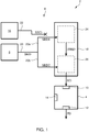
- FIG. 1 shows a schematic view of an automotive testing system 2 according to the invention.
- the system 2 comprises a data processing unit 4, a radar receiving unit 6 and a synthetic radar data generator 8.
- the data processing unit 4 is provided with a data input port 10 for receiving radar data RD and a data output port 12 for transmitting processed data PD, e.g. for the purpose of feeding a control unit for generating control data based on the processed data PD transmitted by the data processing unit 4.
- the processing unit 4 further comprises an additional data input port 14, e.g. for receiving further input data, e.g. camera data.
- the radar receiving unit 6 is arranged for generating and forwarding the radar data RD to the data input port 10 of the data processing unit 4 responsive to a radar excitation signal.
- the radar receiving unit 6 includes a radar sensing unit 16 and an electronic system 18.
- the radar sensing unit 16 is configured for converting an incoming electromagnetic radar signal into an electronic signal, also referred to as raw radar data RRD.
- the radar sensing unit 16 includes an antenna.
- the electronic system 18 is configured for generating the radar data RD based on the raw radar data RDD that are received from said radar sensing element 16, under normal conditions when installed in a vehicle.
- the electronic system receives radar sensor data representing raw radar data received from the radar sensing element.
- the synthetic radar data generator 8 of the automotive testing system 1 is configured to generate and transmit synthetic radar data SRD to the radar receiving unit 6 responsive to a radar excitation signal, thus mimicking radar signals that would occur if the radar receiving unit 6 is mounted on a vehicle facing realistic traffic situations, in order to simulate common real life traffic circumstances for testing the performance of the radar receiving unit 6 and the data processing unit 4 of the automotive testing system 2.
- a data transmission channel 20 is provided interconnecting the synthetic radar data generator 8 to the electronic system 18 of the radar receiving unit 6.
- the data transmission channel 20 can be implemented as a wired transmission channel. However, in principle, the data transmission channel 20 can be formed in another way, e.g. based on wireless transmission technology.
- the radar sensing unit 16 records incoming electromagnetic radar signals, as a response to transmitted radar excitation signals, and converts said incoming radar signals into electronic signals, thus generating raw radar data RRD that is forwarded to the electronic system 18 of the radar receiving unit 6, via a sensor channel 22 interconnecting the radar sensing unit 16 to the electronic system 18.
- the raw radar data RRD generated by the radar sensing unit 16 forms not the basis of the radar data RD forwarded to the processing unit 4.
- the sensor channel 22 is disconnected from the electronic system 18 while the data transmission channel 20 transmitting synthetic radar data SRD is connected to the electronic system 18.
- the transmission of the raw radar data RRD generated by the radar sensing unit 16 can be terminated by physically disconnecting respective transmission channels or by functionally disabling said transmission actions, using software. Further, the radar sensing element 16 can even be removed from the radar receiving unit 6.
- the synthetic radar data SDR may thus include a synthetic representation of real raw radar data generated by the radar sensing element 16.
- the electromagnetic part of the testing environment is effectively simulated thus enabling radar testing opportunities in laboratory conditions.
- the synthetic radar data SDR generated by the synthetic radar data generator include reflection signals that succeed each other and have the same temporal behaviour within a synthetic period that lasts at least an order longer than a time period of the radar excitation signal, exploiting the insight that the timescale of change in the world is much larger than the timescale of the radar signals.
- the synthetic period can be one order, two orders, three or even more orders greater than the time period of the radar excitation signal.
- the reflection signals in the synthetic radar data SDR are invariant during a synthetic time period corresponding to a sampling rate ranging between circa 1 Hz and circa 1 kHz. In practice, the sampling rate can be chosen in a range between circa 20 Hz and circa 60 Hz. However, other sampling rates are also possible, e.g. 10 Hz or 100 Hz.
- the synthetic radar data may include all reflections, in a complex time series, that have the same temporal behaviour within the synthetic period used that lasts at least an order longer than a time period of the radar excitation signal.
- the synthetic radar data can be obtained through an inverse Fourier transform from data generated from a radar model in a spectral domain, e.g. in a range-doppler domain.
- the electronic system 18 of the radar receiving unit 6 includes a pre-processing unit 24 and a digital signal processing unit 26.
- the pre-processing unit 24 is configured for pre-processing the radar sensor data representing the raw radar data, i.e. the synthetic radar data SRD, in the automotive testing system 2. Pre-processing steps may include so-called backend processing such as an analogue to digital conversion step, a sampling step and/or a noise suppressing step, finally resulting in pre-processed radar sensor data PPRD.
- the digital signal processing unit 26 is configured for generating the radar data RD to be forwarded to the data processing unit 4 of the automotive testing system 2, based on the pre-processed radar sensor data PPRD.
- the digital signal processing unit 26 may be arranged for performing a step of object detection, a step of clustering and/or a step of tracking a cluster or object.
- the radar processing steps are related to the applied type of radar signals.
- Various radar signal types may be applied for radar systems in vehicles including frequency modulated continuous wave FMCW, Doppler, frequency-shift keying FSK, binary frequency-shift keying BFSK, phase-shift keying PSK or differential phase-shift keying DPSK.
- FMCW a continuous wave signal is modulated in frequency to produce a linear sweep signal that is transmitted as an excitation signal.
- the echo received later is mixed with a portion of the transmitted signal to produce a beat frequency signal which is proportional with a round trip time covering the two-way distance between the radar and an object.
- the beat frequency signal is subjected to a temporal FFT algorithm and a speed FFT algorithm.
- the result can be visualized in a so-called range-doppler diagram. Radar data that may be obtained using other radar principles may also be represented in a range-doppler diagram.
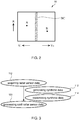
- Figure 2 shows an example of a range-doppler diagram 50 wherein an object velocity V+, V - is a function of the horizontal axis, while an object range R is a function of the vertical axis.
- the diagram or domain 50 contains a mainly vertical band of clutter related reflection data BC.
- Clutter data BC is correlated to stationary objects such as buildings, trees, leaves and grass.
- the diagram or domain further contains reflection data of a first object A moving away from the radar and reflection data of a second object B moving towards the radar.
- the data transmission channel 20 that is used for transmitting the synthetic radar data SRD from the synthetic radar data generator 8 towards the electronic system 18 of the radar receiving unit 6 is connected to both the pre-processing unit 24 and the digital processing unit 26 of the electronic system 18.
- the transmission channel 20 includes a first branch 20a connected to the pre-processing unit 24 for transmitting a first set of synthetic radar data SDR1 with temporal reflection signals.
- the transmission channel 20 further includes a second branch 20b connected to the digital processing unit 26 for transmitting a second set of synthetic radar data SDR2 with range-doppler domain data.
- the above-mentioned second set of synthetic radar data SDR2 includes clustered radar data representing an ensemble of reflecting objects.
- the clustered radar data are related to clutter signals.
- the first set of synthetic radar data SDR1 relates to a temporal representation of radar response signals caused by non-clutter objects such as the first object A and the second object B in the range-doppler diagram 50 moving away from and towards the radar, respectively.
- the second set of synthetic radar data SDR2 relates to a spectral representation of radar response signals caused by clutter objects associated with the clutter data BC in the range-doppler diagram 50.
- the first set of synthetic radar data SDR1 is transmitted to the pre-processing unit 24 while the second set of synthetic radar data SDR2 is transmitted to the digital signal processing unit 26.
- the synthetic radar SDR may be generated from a spectral domain radar model.
- the second set of synthetic radar data SDR2 is directly generated using said spectral domain radar model. Then, a transformation of data to another computational domain might be superfluous, thereby even further reducing computation efforts. Further, any computation of large clutter areas in the time domain, which is inherently computationally demanding especially when performed at a radar timescale of nanoseconds, might be avoided. Again, the insight is exploited that radar reflection signals do not change substantially during the time period of the radar excitation signal because vehicles do not change position that fast.
- a step of clustering data can be performed in the spectral domain as well, i.e. a step of combining reflection signal contributions caused by different reflecting objects in order to process said combined signal contributions together.
- the clustered data relate to reflection signals caused by different clutter objects such as buildings, trees, leaves and grass or other stationary or static objects.
- the clutter objects typically are well known parts of a scene and/or the clutter objects are static or stationary in such a way that the results of processing the associated reflection signals from the time domain into the spectral domain are known in advance.
- the computation of corresponding time domain radar data becomes superfluous, thereby saving computation efforts.
- computation time can be saved if the result of processing steps resulting in spectral data is known in advance, viz. by inserting these spectral data as range-doppler domain data.
- the synthetic radar data SDR may include a synthetic representation of cluster data that is related to a specific object or specific objects, e.g. the object A moving away from the radar, said second synthetic radar data SDR2 being transmitted to the digital signal processing unit 26. Further, almost all synthetic radar data SDR may relate to cluster data in the range-doppler domain, all said synthetic radar data SDR being transmitted to the digital signal processing unit 26. Otherwise, all synthetic radar data SDR may simulate time-domain raw radar data that is transmitted to the pre-processing unit 24. Then, no synthetic radar data SDR is transmitted directly to the digital signal processing unit 26.
- the data processing unit 4 may receive further radar data and/or other sensor signals such as laser signals, infrared signals, radar signals, acoustic signals, ultrasonic signals, pressure signals or electronic signals received in a wired or wireless way and representing any type of measured physical signals associated with automotive conditions or parameters.
- the signals may relate to automotive conditions or parameters of a vehicle in which the sensor unit is mounted or automotive conditions or parameters of other vehicles forwarding such signals to the sensor unit.
- the automotive testing system may include a multiple number of acquisition units such as the described radar receiving unit wherein sensor data are simulated using synthetic radar data. By providing multiple sensor data, a realistic process of processing sensor data may be simulated.
- synthetic radar data simulating radar reflections of a car or another curved surface can be generated using a ray tracing method wherein, via interpolation, a smoothly varying surface normal vector is taken into account when computing reflection caused by an elementary polygon cell in the exterior of said car.
- the surface normal and the radii of curvature between the vertices of the meshes are interpolated so that the surface can be meshed in a relatively coarse way saving computation efforts.
- the exterior of a car has a curved shape.
- the entire reflection can be computed by evaluating the partial reflections caused by the individual polygon cells, e.g. using a ray tracing method, and combining these partial reflections coherently.
- a relatively accurate radar reflection can be computed while computational efforts remain relatively moderate as the exterior surface of the car can be meshed in a relatively coarse manner.
- computational efficiency and accuracy can be improved and any reduction of accuracy caused by the coarse mesh can at least partially be corrected.
- Said optional method of simulating radar reflections from curved surfaces is in itself known from another field of visualization, namely 3D computer graphics, viz. as Phong shading.
- Figure 3 shows a flow chart of an embodiment of a method according to the invention.
- the method is used for automotive testing, and comprises a step of acquiring 110 radar sensor data responsive to a radar excitation signal, and a step of processing 120 said radar sensor data, wherein the step of acquiring 110 radar sensor data includes a substep of generating 112 synthetic radar data and transmitting 114 said synthetic radar data to a radar receiving unit, the synthetic radar data including reflection signals, preferably all reflection signals, in a complex time series, that succeed each other and have the same temporal behaviour within a synthetic period that lasts at least an order of magnitude longer than a time period of the radar excitation signal.
- the method of automotive testing can be facilitated using dedicated hardware structures, such as computer servers. Otherwise, the method can also at least partially be performed using a computer program product comprising instructions for causing a processor of a computer system to facilitate automotive testing. All (sub)steps can in principle be performed on a single processor. However, it is noted that at least one step can be performed on a separate processor.
- a processor can be loaded with a specific software module.
- Dedicated software modules can be provided, e.g. from the Internet.
- the electronic system 23 of the radar receiving unit 6 may include a single or a multiple number of units for processing radar data.
- generating synthetic radar data simulating radar reflections of a car using a ray tracing method wherein the surface normal and the radii of curvature between the vertices of the meshes are interpolated, so that an interpolating smoothly varying surface normal vector is taken into account when computing reflection caused by an elementary polygon cell in the exterior of a car or another curved surface can not only be used in the claimed automotive testing method, but more generally in automotive testing, comprising the steps of acquiring radar sensor data and processing said radar sensor data.
Abstract
The invention relates to an automotive testing method. The method comprises a step of acquiring radar sensor data responsive to a radar excitation signal. Further, the method includes a step of processing said radar sensor data. The step of acquiring raw radar data includes generating synthetic radar data and transmitting said synthetic radar data to a radar receiving unit. Here, the synthetic radar data includes reflection signals, preferably all reflection signals, in a complex time series, that succeed each other and have the same temporal behaviour within a synthetic period that lasts at least an order longer than a time period of the radar excitation signal.
Description
- The invention relates to an automotive testing method.
- Automotive testing systems are known for the purpose of testing data acquisition units and data processing units processing sensor input data generated by said data acquisition units, thereby reducing expensive testing equipment and testing time in realistic traffic circumstances. As an example, data acquisition units can be provided with a camera unit having an optic system and an electronic system for capturing image data.
- However, so far, radar systems have to be tested in realistic circumstances in order evaluate how said systems react on radar input data. In this respect it is noted that radar systems have a high data rate relative to the time scale of the radar signals.
- It is an object of the invention to provide an automotive testing method that enables testing a radar system in laboratory circumstances. Thereto, according to the invention, an automotive testing method is provided comprising the steps of acquiring radar sensor data responsive to a radar excitation signal and processing said radar sensor data, wherein the step of acquiring raw radar data includes generating synthetic radar data and transmitting said synthetic radar data to a radar receiving unit, the synthetic radar data including reflection signals that succeed each other and have the same temporal behaviour within a synthetic period that lasts at least an order longer than a time period of the radar excitation signal.
- The invention is at least partly based on the insight that radar data do not significantly change in the time scale of the radar signals since vehicles do not move along relevant distances during a time period of a radar excitation signal, i.e. nanoseconds.
- By generating synthetic radar data including reflection signals that succeed each other and have the same temporal behaviour within a synthetic period that lasts at least an order longer than a time period of the radar excitation signal, only a reduced number of reflection signals has to be computed per synthetic period wherein the objects that are exposed to the radar excitation signal hardly move relative to each other. Then, there is substantially no loss in accuracy while, on the other hand, a considerably reduction of computational efforts is realized when carrying out a simulation of radar reflection signals. The synthetic radar data may include all reflections, in a complex time series, that have the same temporal behaviour within the synthetic period used that lasts at least an order longer than a time period of the radar excitation signal.
- It is noted that, within the context of the application, the expression "synthetic radar data" is to be understood as radar data that has been generated electronically by simulating data that is normally sensed by a radar sensing element converting an incoming radar signal into an electronic signal, also referred to as raw radar data.
- Advantageously, the synthetic radar data can be generated from a spectral domain radar model, e.g. using an inverse FFT routine to generate the reflection signals.
- Preferably, the synthetic radar data includes a first set of radar data with temporal reflection signals to be input to a pre-processing unit that is arranged for pre-processing radar sensor data, and a second set of radar data with range-doppler domain data to be input to a digital signal processing unit for evaluating radar data in the range-doppler domain.
- The invention also relates to a system.
- Further, the invention relates to a computer program product. A computer program product may comprise a set of computer executable instructions stored on a data carrier, such as a flash memory, a CD or a DVD. The set of computer executable instructions, which allow a programmable computer to carry out the method as defined above, may also be available for downloading from a remote server, for example via the Internet, e.g. as an app.
- Other advantageous options and embodiments according to the invention are described in the following claims.
- By way of example only, embodiments of the present invention will now be described with reference to the accompanying figures in which
-
Fig. 1 shows a schematic view of an automotive testing system according to the invention; -
Fig. 2 shows a range-doppler diagram, and -
Fig. 3 shows a flow chart of a method according to the invention. - The figures merely illustrate preferred embodiments according to the invention. In the figures, the same reference numbers refer to equal or corresponding parts.
-
Figure 1 shows a schematic view of anautomotive testing system 2 according to the invention. Thesystem 2 comprises adata processing unit 4, aradar receiving unit 6 and a syntheticradar data generator 8. - The
data processing unit 4 is provided with adata input port 10 for receiving radar data RD and adata output port 12 for transmitting processed data PD, e.g. for the purpose of feeding a control unit for generating control data based on the processed data PD transmitted by thedata processing unit 4. In the shown embodiment, theprocessing unit 4 further comprises an additionaldata input port 14, e.g. for receiving further input data, e.g. camera data. - The
radar receiving unit 6 is arranged for generating and forwarding the radar data RD to thedata input port 10 of thedata processing unit 4 responsive to a radar excitation signal. Theradar receiving unit 6 includes aradar sensing unit 16 and anelectronic system 18. Theradar sensing unit 16 is configured for converting an incoming electromagnetic radar signal into an electronic signal, also referred to as raw radar data RRD. Typically, theradar sensing unit 16 includes an antenna. Theelectronic system 18 is configured for generating the radar data RD based on the raw radar data RDD that are received from saidradar sensing element 16, under normal conditions when installed in a vehicle. Generally, for the purpose of generating the radar data RD, the electronic system receives radar sensor data representing raw radar data received from the radar sensing element. - Further, the synthetic
radar data generator 8 of the automotive testing system 1 is configured to generate and transmit synthetic radar data SRD to theradar receiving unit 6 responsive to a radar excitation signal, thus mimicking radar signals that would occur if theradar receiving unit 6 is mounted on a vehicle facing realistic traffic situations, in order to simulate common real life traffic circumstances for testing the performance of theradar receiving unit 6 and thedata processing unit 4 of theautomotive testing system 2. For the purpose of transmitting the synthetic radar data SRD to theradar receiving unit 6, adata transmission channel 20 is provided interconnecting the syntheticradar data generator 8 to theelectronic system 18 of theradar receiving unit 6. Thedata transmission channel 20 can be implemented as a wired transmission channel. However, in principle, thedata transmission channel 20 can be formed in another way, e.g. based on wireless transmission technology. - During regular operation of the
radar receiving unit 6, in a vehicle, theradar sensing unit 16 records incoming electromagnetic radar signals, as a response to transmitted radar excitation signals, and converts said incoming radar signals into electronic signals, thus generating raw radar data RRD that is forwarded to theelectronic system 18 of theradar receiving unit 6, via asensor channel 22 interconnecting theradar sensing unit 16 to theelectronic system 18. - According to an aspect of the invention, the raw radar data RRD generated by the
radar sensing unit 16 forms not the basis of the radar data RD forwarded to theprocessing unit 4. In the shown embodiment, thesensor channel 22 is disconnected from theelectronic system 18 while thedata transmission channel 20 transmitting synthetic radar data SRD is connected to theelectronic system 18. In principle, the transmission of the raw radar data RRD generated by theradar sensing unit 16 can be terminated by physically disconnecting respective transmission channels or by functionally disabling said transmission actions, using software. Further, theradar sensing element 16 can even be removed from theradar receiving unit 6. - Then, electronic radar sensor signals are simulated by the synthetic
radar data generator 8 so that the radar data generated by theradar receiving unit 6 are based on the synthetic radar data SRD transmitted to theelectronic system 18 of theradar receiving unit 6. The synthetic radar data SDR may thus include a synthetic representation of real raw radar data generated by theradar sensing element 16. - By bypassing the
radar sensing element 16 of theradar receiving unit 6, the electromagnetic part of the testing environment is effectively simulated thus enabling radar testing opportunities in laboratory conditions. - The synthetic radar data SDR generated by the synthetic radar data generator include reflection signals that succeed each other and have the same temporal behaviour within a synthetic period that lasts at least an order longer than a time period of the radar excitation signal, exploiting the insight that the timescale of change in the world is much larger than the timescale of the radar signals. By rendering synthetic radar data SDR that include successive identical reflection signals, computational efforts are reduced considerably. The synthetic period can be one order, two orders, three or even more orders greater than the time period of the radar excitation signal. As an example, the reflection signals in the synthetic radar data SDR are invariant during a synthetic time period corresponding to a sampling rate ranging between circa 1 Hz and circa 1 kHz. In practice, the sampling rate can be chosen in a range between circa 20 Hz and circa 60 Hz. However, other sampling rates are also possible, e.g. 10 Hz or 100 Hz.
- The synthetic radar data may include all reflections, in a complex time series, that have the same temporal behaviour within the synthetic period used that lasts at least an order longer than a time period of the radar excitation signal.
- Advantageously, the synthetic radar data can be obtained through an inverse Fourier transform from data generated from a radar model in a spectral domain, e.g. in a range-doppler domain.
- In the embodiment shown in
Fig. 1 theelectronic system 18 of theradar receiving unit 6 includes apre-processing unit 24 and a digitalsignal processing unit 26. Thepre-processing unit 24 is configured for pre-processing the radar sensor data representing the raw radar data, i.e. the synthetic radar data SRD, in theautomotive testing system 2. Pre-processing steps may include so-called backend processing such as an analogue to digital conversion step, a sampling step and/or a noise suppressing step, finally resulting in pre-processed radar sensor data PPRD. The digitalsignal processing unit 26 is configured for generating the radar data RD to be forwarded to thedata processing unit 4 of theautomotive testing system 2, based on the pre-processed radar sensor data PPRD. Specifically, the digitalsignal processing unit 26 may be arranged for performing a step of object detection, a step of clustering and/or a step of tracking a cluster or object. - Generally, the radar processing steps are related to the applied type of radar signals. Various radar signal types may be applied for radar systems in vehicles including frequency modulated continuous wave FMCW, Doppler, frequency-shift keying FSK, binary frequency-shift keying BFSK, phase-shift keying PSK or differential phase-shift keying DPSK. In case of FMCW, a continuous wave signal is modulated in frequency to produce a linear sweep signal that is transmitted as an excitation signal. The echo received later is mixed with a portion of the transmitted signal to produce a beat frequency signal which is proportional with a round trip time covering the two-way distance between the radar and an object. Then, the beat frequency signal is subjected to a temporal FFT algorithm and a speed FFT algorithm. The result can be visualized in a so-called range-doppler diagram. Radar data that may be obtained using other radar principles may also be represented in a range-doppler diagram.
-
Figure 2 shows an example of a range-doppler diagram 50 wherein an object velocity V+, V- is a function of the horizontal axis, while an object range R is a function of the vertical axis. The diagram ordomain 50 contains a mainly vertical band of clutter related reflection data BC. Clutter data BC is correlated to stationary objects such as buildings, trees, leaves and grass. The diagram or domain further contains reflection data of a first object A moving away from the radar and reflection data of a second object B moving towards the radar. - In the embodiment shown in
Fig. 1 , thedata transmission channel 20 that is used for transmitting the synthetic radar data SRD from the syntheticradar data generator 8 towards theelectronic system 18 of theradar receiving unit 6 is connected to both thepre-processing unit 24 and thedigital processing unit 26 of theelectronic system 18. Thetransmission channel 20 includes afirst branch 20a connected to thepre-processing unit 24 for transmitting a first set of synthetic radar data SDR1 with temporal reflection signals. Thetransmission channel 20 further includes asecond branch 20b connected to thedigital processing unit 26 for transmitting a second set of synthetic radar data SDR2 with range-doppler domain data. - The above-mentioned second set of synthetic radar data SDR2 includes clustered radar data representing an ensemble of reflecting objects. Preferably, the clustered radar data are related to clutter signals.
- Then, the first set of synthetic radar data SDR1 relates to a temporal representation of radar response signals caused by non-clutter objects such as the first object A and the second object B in the range-doppler diagram 50 moving away from and towards the radar, respectively. The second set of synthetic radar data SDR2 relates to a spectral representation of radar response signals caused by clutter objects associated with the clutter data BC in the range-doppler diagram 50. The first set of synthetic radar data SDR1 is transmitted to the
pre-processing unit 24 while the second set of synthetic radar data SDR2 is transmitted to the digitalsignal processing unit 26. - As indicated above, the synthetic radar SDR may be generated from a spectral domain radar model. Advantageously, the second set of synthetic radar data SDR2 is directly generated using said spectral domain radar model. Then, a transformation of data to another computational domain might be superfluous, thereby even further reducing computation efforts. Further, any computation of large clutter areas in the time domain, which is inherently computationally demanding especially when performed at a radar timescale of nanoseconds, might be avoided. Again, the insight is exploited that radar reflection signals do not change substantially during the time period of the radar excitation signal because vehicles do not change position that fast.
- Further, a step of clustering data can be performed in the spectral domain as well, i.e. a step of combining reflection signal contributions caused by different reflecting objects in order to process said combined signal contributions together. In the above-described implementation the clustered data relate to reflection signals caused by different clutter objects such as buildings, trees, leaves and grass or other stationary or static objects. The clutter objects typically are well known parts of a scene and/or the clutter objects are static or stationary in such a way that the results of processing the associated reflection signals from the time domain into the spectral domain are known in advance. By forwarding the processed data in the range-doppler domain, the computation of corresponding time domain radar data becomes superfluous, thereby saving computation efforts. Generally, computation time can be saved if the result of processing steps resulting in spectral data is known in advance, viz. by inserting these spectral data as range-doppler domain data.
- Alternatively, the synthetic radar data SDR may include a synthetic representation of cluster data that is related to a specific object or specific objects, e.g. the object A moving away from the radar, said second synthetic radar data SDR2 being transmitted to the digital
signal processing unit 26. Further, almost all synthetic radar data SDR may relate to cluster data in the range-doppler domain, all said synthetic radar data SDR being transmitted to the digitalsignal processing unit 26. Otherwise, all synthetic radar data SDR may simulate time-domain raw radar data that is transmitted to thepre-processing unit 24. Then, no synthetic radar data SDR is transmitted directly to the digitalsignal processing unit 26. - It is noted that the
data processing unit 4 may receive further radar data and/or other sensor signals such as laser signals, infrared signals, radar signals, acoustic signals, ultrasonic signals, pressure signals or electronic signals received in a wired or wireless way and representing any type of measured physical signals associated with automotive conditions or parameters. The signals may relate to automotive conditions or parameters of a vehicle in which the sensor unit is mounted or automotive conditions or parameters of other vehicles forwarding such signals to the sensor unit. It is further noted that the automotive testing system may include a multiple number of acquisition units such as the described radar receiving unit wherein sensor data are simulated using synthetic radar data. By providing multiple sensor data, a realistic process of processing sensor data may be simulated. - Optionally, synthetic radar data simulating radar reflections of a car or another curved surface can be generated using a ray tracing method wherein, via interpolation, a smoothly varying surface normal vector is taken into account when computing reflection caused by an elementary polygon cell in the exterior of said car. Here, the surface normal and the radii of curvature between the vertices of the meshes are interpolated so that the surface can be meshed in a relatively coarse way saving computation efforts. Generally, the exterior of a car has a curved shape. By meshing the exterior of said car, or at least a portion of said car exterior receiving an incident radar beam, into a multiple number of elementary polygon cells, the entire reflection can be computed by evaluating the partial reflections caused by the individual polygon cells, e.g. using a ray tracing method, and combining these partial reflections coherently. Advantageously, when smoothly varying the surface normal vector of the individual polygon cells, in an interpolating manner, a relatively accurate radar reflection can be computed while computational efforts remain relatively moderate as the exterior surface of the car can be meshed in a relatively coarse manner. As a result, computational efficiency and accuracy can be improved and any reduction of accuracy caused by the coarse mesh can at least partially be corrected. Said optional method of simulating radar reflections from curved surfaces is in itself known from another field of visualization, namely 3D computer graphics, viz. as Phong shading.
-
Figure 3 shows a flow chart of an embodiment of a method according to the invention. The method is used for automotive testing, and comprises a step of acquiring 110 radar sensor data responsive to a radar excitation signal, and a step of processing 120 said radar sensor data, wherein the step of acquiring 110 radar sensor data includes a substep of generating 112 synthetic radar data and transmitting 114 said synthetic radar data to a radar receiving unit, the synthetic radar data including reflection signals, preferably all reflection signals, in a complex time series, that succeed each other and have the same temporal behaviour within a synthetic period that lasts at least an order of magnitude longer than a time period of the radar excitation signal. - The method of automotive testing can be facilitated using dedicated hardware structures, such as computer servers. Otherwise, the method can also at least partially be performed using a computer program product comprising instructions for causing a processor of a computer system to facilitate automotive testing. All (sub)steps can in principle be performed on a single processor. However, it is noted that at least one step can be performed on a separate processor. A processor can be loaded with a specific software module. Dedicated software modules can be provided, e.g. from the Internet.
- The invention is not restricted to the embodiments described herein. It will be understood that many variants are possible.
- It is noted that the electronic system 23 of the
radar receiving unit 6 may include a single or a multiple number of units for processing radar data. - It is further noted that generating synthetic radar data simulating radar reflections of a car using a ray tracing method wherein the surface normal and the radii of curvature between the vertices of the meshes are interpolated, so that an interpolating smoothly varying surface normal vector is taken into account when computing reflection caused by an elementary polygon cell in the exterior of a car or another curved surface, can not only be used in the claimed automotive testing method, but more generally in automotive testing, comprising the steps of acquiring radar sensor data and processing said radar sensor data.
- These and other embodiments will be apparent for the person skilled in the art and are considered to fall within the scope of the invention as defined in the following claims. For the purpose of clarity and a concise description features are described herein as part of the same or separate embodiments. However, it will be appreciated that the scope of the invention may include embodiments having combinations of all or some of the features described.
Claims (15)
- An automotive testing method, comprising the steps of:- acquiring radar sensor data responsive to a radar excitation signal and- processing said radar sensor data,wherein the step of acquiring raw radar data includes generating synthetic radar data and transmitting said synthetic radar data to a radar receiving unit, the synthetic radar data including reflection signals that succeed each other and have the same temporal behaviour within a synthetic period that lasts at least an order longer than a time period of the radar excitation signal.
- An automotive testing system according to claim 1, wherein the synthetic radar data include all reflection signals, in a complex time series, that succeed each other and have the same temporal behaviour within a synthetic period that lasts at least an order longer than a time period of the radar excitation signal.
- An automotive testing system according to claim 1 or 2, wherein the synthetic period corresponds to a sampling rate ranging between circa 1 Hz and circa 1 kHz.
- An automotive testing method according to any of the preceding claims, wherein the step of transmitting said synthetic radar data to the radar receiving unit includes bypassing a radar sensing element converting an incoming radar signal into an electronic signal.
- An automotive testing method according to any of the preceding claims, wherein the synthetic radar data are generated from a spectral domain radar model.
- An automotive testing method according to any of the preceding claims, wherein the synthetic radar data includes a first set of radar data with temporal reflection signals.
- An automotive testing method according to any of the preceding claims, wherein the synthetic radar data includes a second set of radar data with range-doppler domain data.
- An automotive testing method according to claim 7, wherein the second set of radar data includes clustered radar data representing an ensemble of reflecting objects.
- An automotive testing method according to claim 8, wherein the clustered radar data are related to clutter signals.
- An automotive testing method according to any of the preceding claims, wherein synthetic radar data simulating radar reflections of a car are generated including the steps of:- meshing the exterior surface of the car coarsely, and- applying a using a ray tracing method while interpolating the surface normal and the radii of curvature between vertices of the meshes.
- An automotive testing system, comprising a data processing unit provided with a data input port for receiving radar data and a data output port for transmitting processed data, further comprising a radar receiving unit forwarding radar data to said data processing unit responsive to a radar excitation signal, wherein the testing system further comprises a synthetic radar data generator that is configured for transmitting synthetic radar data to the radar receiving unit, the synthetic radar data including reflection signals that succeed each other and have the same temporal behaviour within a synthetic period that lasts at least an order longer than a time period of the radar excitation signal.
- An automotive testing system according to claim 11, wherein the radar receiving unit includes an electronic system for generating the radar data based on radar sensor data representing raw radar data received from a radar sensing element converting an incoming radar signal into an electronic signal, and wherein the testing system further comprises a data transmission channel interconnecting the synthetic radar data generator to the electronic system of the radar receiving unit.
- An automotive testing system according to claim 12, wherein the electronic system of the radar receiving unit comprises a pre-processing unit for pre-processing the radar sensor data, and a digital signal processing unit for generating, based on the pre-processed radar sensor data, the radar data to be forwarded to the data processing unit, and
wherein the data transmission channel includes a first branch connected to the pre-processing unit of the electronic system. - An automotive testing system according to claim 13, wherein the data transmission channel includes a second branch connected to the digital signal processing unit of the electronic system.
- A computer program product for automotive testing, the computer program product comprising computer readable code for causing a processor to perform the steps of:- acquiring raw radar data responsive to a radar excitation signal and- processing said radar data,wherein the step of acquiring raw radar data includes generating synthetic radar data and transmitting said synthetic radar data to a radar receiving unit, the synthetic radar data including reflection signals that succeed each other and have the same temporal behaviour within a synthetic period that lasts at least an order longer than a time period of the radar excitation signal.
Priority Applications (4)
| Application Number | Priority Date | Filing Date | Title |
|---|---|---|---|
| EP16176196.0A EP3260875A1 (en) | 2016-06-24 | 2016-06-24 | An automotive testing method, system and computer program product |
| PCT/NL2017/050425 WO2017222385A1 (en) | 2016-06-24 | 2017-06-26 | An automotive testing method, system and computer program product |
| EP17737905.4A EP3446145A1 (en) | 2016-06-24 | 2017-06-26 | An automotive testing method, system and computer program product |
| US16/312,536 US11255962B2 (en) | 2016-06-24 | 2017-06-26 | Automotive testing method, system and computer program product |
Applications Claiming Priority (1)
| Application Number | Priority Date | Filing Date | Title |
|---|---|---|---|
| EP16176196.0A EP3260875A1 (en) | 2016-06-24 | 2016-06-24 | An automotive testing method, system and computer program product |
Publications (1)
| Publication Number | Publication Date |
|---|---|
| EP3260875A1 true EP3260875A1 (en) | 2017-12-27 |
Family
ID=56555170
Family Applications (2)
| Application Number | Title | Priority Date | Filing Date |
|---|---|---|---|
| EP16176196.0A Withdrawn EP3260875A1 (en) | 2016-06-24 | 2016-06-24 | An automotive testing method, system and computer program product |
| EP17737905.4A Pending EP3446145A1 (en) | 2016-06-24 | 2017-06-26 | An automotive testing method, system and computer program product |
Family Applications After (1)
| Application Number | Title | Priority Date | Filing Date |
|---|---|---|---|
| EP17737905.4A Pending EP3446145A1 (en) | 2016-06-24 | 2017-06-26 | An automotive testing method, system and computer program product |
Country Status (3)
| Country | Link |
|---|---|
| US (1) | US11255962B2 (en) |
| EP (2) | EP3260875A1 (en) |
| WO (1) | WO2017222385A1 (en) |
Cited By (5)
| Publication number | Priority date | Publication date | Assignee | Title |
|---|---|---|---|---|
| CN109782241A (en) * | 2019-03-29 | 2019-05-21 | 北京润科通用技术有限公司 | A kind of meteorological radar echo analogy method and system |
| FR3076900A1 (en) * | 2018-01-17 | 2019-07-19 | Institut De Recherche Technologique Systemx | METHOD FOR DETERMINING THE RESPONSE OF A MEASURING SYSTEM AND METHOD AND DEVICES THEREFOR |
| AT521120A1 (en) * | 2018-04-13 | 2019-10-15 | Avl List Gmbh | Method and device for determining a radar cross section, method for training an interaction model as well as radar target emulator and test stand |
| US20200111382A1 (en) * | 2018-10-04 | 2020-04-09 | The Regents Of The University Of Michigan | Automotive Radar Scene Simulator |
| WO2021004626A1 (en) * | 2019-07-09 | 2021-01-14 | Siemens Industry Software And Services B.V. | A method to simulate continuous wave lidar sensors |
Families Citing this family (4)
| Publication number | Priority date | Publication date | Assignee | Title |
|---|---|---|---|---|
| EP3517996B1 (en) * | 2018-01-25 | 2022-09-07 | Aptiv Technologies Limited | Method for determining the position of a vehicle |
| US10754008B2 (en) * | 2018-02-15 | 2020-08-25 | GM Global Technology Operations LLC | Vehicle radar system that addresses doppler frequency shift and method of using the same |
| JP7280458B2 (en) | 2019-04-04 | 2023-05-24 | シーメンス インダストリー ソフトウェア エヌヴェ | How to run a simulation of radar raw data on a computer |
| CN116461539A (en) * | 2023-04-10 | 2023-07-21 | 北京辉羲智能科技有限公司 | Automatic driving SoC chip for collecting time sequence data of sensor |
Citations (3)
| Publication number | Priority date | Publication date | Assignee | Title |
|---|---|---|---|---|
| US4660041A (en) * | 1983-09-22 | 1987-04-21 | Boeing Aerospace Company | Radar scene simulator |
| US5223840A (en) * | 1992-03-13 | 1993-06-29 | The United States Of America As Represented By The Secretary Of The Navy | Low cost radar target simulator for remote radar testing |
| US7567205B1 (en) * | 2008-09-18 | 2009-07-28 | Raytheon Company | Dynamic ray traversing |
Family Cites Families (3)
| Publication number | Priority date | Publication date | Assignee | Title |
|---|---|---|---|---|
| CA2110692A1 (en) * | 1991-06-05 | 1992-12-10 | Leslie John Vencel | Radar return signal simulator |
| US8538071B2 (en) * | 2009-03-18 | 2013-09-17 | Raytheon Company | System and method for target separation of closely spaced targets in automatic target recognition |
| SE538908C2 (en) * | 2015-10-22 | 2017-02-07 | Uniquesec Ab | Testing method with virtual radar signatures for an automotive safety radar system |
-
2016
- 2016-06-24 EP EP16176196.0A patent/EP3260875A1/en not_active Withdrawn
-
2017
- 2017-06-26 EP EP17737905.4A patent/EP3446145A1/en active Pending
- 2017-06-26 WO PCT/NL2017/050425 patent/WO2017222385A1/en active Application Filing
- 2017-06-26 US US16/312,536 patent/US11255962B2/en active Active
Patent Citations (3)
| Publication number | Priority date | Publication date | Assignee | Title |
|---|---|---|---|---|
| US4660041A (en) * | 1983-09-22 | 1987-04-21 | Boeing Aerospace Company | Radar scene simulator |
| US5223840A (en) * | 1992-03-13 | 1993-06-29 | The United States Of America As Represented By The Secretary Of The Navy | Low cost radar target simulator for remote radar testing |
| US7567205B1 (en) * | 2008-09-18 | 2009-07-28 | Raytheon Company | Dynamic ray traversing |
Non-Patent Citations (3)
| Title |
|---|
| ERGEZER HALIT ET AL: "Hardware-in-the-loop radar test simulator", 2014 4TH INTERNATIONAL CONFERENCE ON SIMULATION AND MODELING METHODOLOGIES, TECHNOLOGIES AND APPLICATIONS (SIMULTECH), SCITEPRESS, 28 August 2014 (2014-08-28), pages 666 - 673, XP032768670 * |
| HAO HUANG ET AL: "Hardware-in-the-loop simulation technology of wide-band radar targets based on scattering center model", CHINESE JOURNAL OF AERONAUTICS, vol. 28, no. 5, 1 October 2015 (2015-10-01), AMSTERDAM, NL, pages 1476 - 1484, XP055325574, ISSN: 1000-9361, DOI: 10.1016/j.cja.2015.07.006 * |
| MARCO WEISKOPF ET AL: "Integrationslösung zur Absicherung eines realen Radarsensors im Systemverbund mit der Hardware-in-the- Loop Testtechnologie", 16 April 2015 (2015-04-16), XP055325566, Retrieved from the Internet <URL:http://subs.emis.de/LNI/Proceedings/Proceedings240/29.pdf> [retrieved on 20161202] * |
Cited By (12)
| Publication number | Priority date | Publication date | Assignee | Title |
|---|---|---|---|---|
| FR3076900A1 (en) * | 2018-01-17 | 2019-07-19 | Institut De Recherche Technologique Systemx | METHOD FOR DETERMINING THE RESPONSE OF A MEASURING SYSTEM AND METHOD AND DEVICES THEREFOR |
| AT521120A1 (en) * | 2018-04-13 | 2019-10-15 | Avl List Gmbh | Method and device for determining a radar cross section, method for training an interaction model as well as radar target emulator and test stand |
| AT521120B1 (en) * | 2018-04-13 | 2022-02-15 | Avl List Gmbh | Method and device for determining a radar cross section, method for training an interaction model and radar target emulator and test bench |
| US11899130B2 (en) | 2018-04-13 | 2024-02-13 | Avl List Gmbh | Method and device for determining a radar cross section, method for training an interaction model, and radar target emulator and test facility |
| US20200111382A1 (en) * | 2018-10-04 | 2020-04-09 | The Regents Of The University Of Michigan | Automotive Radar Scene Simulator |
| US11875708B2 (en) * | 2018-10-04 | 2024-01-16 | The Regents Of The University Of Michigan | Automotive radar scene simulator |
| CN109782241A (en) * | 2019-03-29 | 2019-05-21 | 北京润科通用技术有限公司 | A kind of meteorological radar echo analogy method and system |
| CN109782241B (en) * | 2019-03-29 | 2021-01-29 | 北京润科通用技术有限公司 | Meteorological radar echo simulation method and system |
| WO2021004626A1 (en) * | 2019-07-09 | 2021-01-14 | Siemens Industry Software And Services B.V. | A method to simulate continuous wave lidar sensors |
| CN114072697A (en) * | 2019-07-09 | 2022-02-18 | 西门子工业软件荷兰有限公司 | Method for simulating continuous wave lidar sensor |
| US11460562B2 (en) | 2019-07-09 | 2022-10-04 | Siemens Industry Software Netherlands B.V. | Methods to simulate continuous wave lidar sensors |
| CN114072697B (en) * | 2019-07-09 | 2023-03-24 | 西门子工业软件公司 | Method for simulating continuous wave lidar sensor |
Also Published As
| Publication number | Publication date |
|---|---|
| US20190227164A1 (en) | 2019-07-25 |
| EP3446145A1 (en) | 2019-02-27 |
| WO2017222385A1 (en) | 2017-12-28 |
| US11255962B2 (en) | 2022-02-22 |
Similar Documents
| Publication | Publication Date | Title |
|---|---|---|
| EP3260875A1 (en) | An automotive testing method, system and computer program product | |
| US11867834B2 (en) | Sensor independent reduced-order model for real-time radar simulation in a dynamic environment | |
| EP0790753A1 (en) | System for sound spatial effect and method therefor | |
| US9261593B1 (en) | Higher order processing for synthetic aperture radar (SAR) | |
| CN111830493B (en) | System and method for forecasting strength of middle-high frequency sound target in underwater target receiving and transmitting division | |
| WO2020250231A1 (en) | System and method of enhancing a performance of an electromagnetic sensor | |
| KR101478639B1 (en) | Service system Of Synthetic Oceanography Environment Data | |
| CN114460588B (en) | High-precision imaging method based on active acoustic imager | |
| JPWO2018003158A1 (en) | Correlation function generation device, correlation function generation method, correlation function generation program and wave source direction estimation device | |
| JP2010127771A (en) | Synthetic aperture sonar, and method and program for correcting phase error of synthetic aperture sonar | |
| US9035820B2 (en) | Measurement device, measurement system, measurement method, and program | |
| CN116466307B (en) | Millimeter wave Lei Dadian cloud simulation method and device based on depth map | |
| CN113849969A (en) | Millimeter wave radar simulation method and device and electronic equipment | |
| CN116467848B (en) | Millimeter wave radar point cloud simulation method and device | |
| CN112630798B (en) | Method and apparatus for estimating ground | |
| CN113325408A (en) | Noise estimation method, device and related equipment | |
| CN107133385B (en) | Multi-mode synthetic aperture radar echo signal simulation method based on mode variation | |
| CN108919217A (en) | A kind of Processing Method of Point-clouds, device, controller and radar sensor | |
| CN114924246A (en) | Target detection method, target detection device, millimeter wave radar and storage medium | |
| CN111045010B (en) | Environment reconstruction method and device based on shipborne radar | |
| CN113406650A (en) | Three-dimensional side scan sonar array forming method and equipment | |
| KR102659304B1 (en) | Method and system for generating synthetic aperture radar data | |
| JP2020143920A (en) | Model generation device, vehicle simulation system, model generation method, vehicle simulation method, and computer program | |
| CN117031366B (en) | Method and system for monitoring rough sea surface electromagnetic wave propagation | |
| CN116451590B (en) | Simulation method and device of automatic driving simulation test platform |
Legal Events
| Date | Code | Title | Description |
|---|---|---|---|
| PUAI | Public reference made under article 153(3) epc to a published international application that has entered the european phase |
Free format text: ORIGINAL CODE: 0009012 |
|
| STAA | Information on the status of an ep patent application or granted ep patent |
Free format text: STATUS: THE APPLICATION HAS BEEN PUBLISHED |
|
| AK | Designated contracting states |
Kind code of ref document: A1 Designated state(s): AL AT BE BG CH CY CZ DE DK EE ES FI FR GB GR HR HU IE IS IT LI LT LU LV MC MK MT NL NO PL PT RO RS SE SI SK SM TR |
|
| AX | Request for extension of the european patent |
Extension state: BA ME |
|
| STAA | Information on the status of an ep patent application or granted ep patent |
Free format text: STATUS: THE APPLICATION IS DEEMED TO BE WITHDRAWN |
|
| 18D | Application deemed to be withdrawn |
Effective date: 20180628 |