WO2014167964A1 - 赤外線反射フィルム - Google Patents
赤外線反射フィルム Download PDFInfo
- Publication number
- WO2014167964A1 WO2014167964A1 PCT/JP2014/057516 JP2014057516W WO2014167964A1 WO 2014167964 A1 WO2014167964 A1 WO 2014167964A1 JP 2014057516 W JP2014057516 W JP 2014057516W WO 2014167964 A1 WO2014167964 A1 WO 2014167964A1
- Authority
- WO
- WIPO (PCT)
- Prior art keywords
- layer
- infrared
- infrared reflective
- metal oxide
- metal
- Prior art date
Links
- 239000010410 layer Substances 0.000 claims abstract description 266
- 239000011241 protective layer Substances 0.000 claims abstract description 98
- 229910052751 metal Inorganic materials 0.000 claims abstract description 87
- 239000002184 metal Substances 0.000 claims abstract description 87
- 229910044991 metal oxide Inorganic materials 0.000 claims abstract description 83
- 150000004706 metal oxides Chemical class 0.000 claims abstract description 83
- 238000002834 transmittance Methods 0.000 claims abstract description 48
- 239000000463 material Substances 0.000 claims abstract description 38
- BQCADISMDOOEFD-UHFFFAOYSA-N Silver Chemical compound [Ag] BQCADISMDOOEFD-UHFFFAOYSA-N 0.000 claims abstract description 27
- 239000004332 silver Substances 0.000 claims abstract description 27
- 229910052709 silver Inorganic materials 0.000 claims abstract description 26
- 229910001316 Ag alloy Inorganic materials 0.000 claims abstract description 7
- 239000000758 substrate Substances 0.000 claims description 42
- XLOMVQKBTHCTTD-UHFFFAOYSA-N Zinc monoxide Chemical compound [Zn]=O XLOMVQKBTHCTTD-UHFFFAOYSA-N 0.000 claims description 28
- KDLHZDBZIXYQEI-UHFFFAOYSA-N Palladium Chemical compound [Pd] KDLHZDBZIXYQEI-UHFFFAOYSA-N 0.000 claims description 25
- 239000002131 composite material Substances 0.000 claims description 21
- 239000011787 zinc oxide Substances 0.000 claims description 14
- FAPWRFPIFSIZLT-UHFFFAOYSA-M Sodium chloride Chemical compound [Na+].[Cl-] FAPWRFPIFSIZLT-UHFFFAOYSA-M 0.000 claims description 10
- 229910052763 palladium Inorganic materials 0.000 claims description 9
- 230000008859 change Effects 0.000 claims description 7
- 239000007864 aqueous solution Substances 0.000 claims description 5
- 239000011248 coating agent Substances 0.000 claims description 5
- 238000000576 coating method Methods 0.000 claims description 5
- 239000011780 sodium chloride Substances 0.000 claims description 5
- GZCWPZJOEIAXRU-UHFFFAOYSA-N tin zinc Chemical compound [Zn].[Sn] GZCWPZJOEIAXRU-UHFFFAOYSA-N 0.000 claims description 5
- NJWNEWQMQCGRDO-UHFFFAOYSA-N indium zinc Chemical compound [Zn].[In] NJWNEWQMQCGRDO-UHFFFAOYSA-N 0.000 claims description 4
- WGCXSIWGFOQDEG-UHFFFAOYSA-N [Zn].[Sn].[In] Chemical compound [Zn].[Sn].[In] WGCXSIWGFOQDEG-UHFFFAOYSA-N 0.000 claims description 3
- 238000007654 immersion Methods 0.000 claims description 3
- 239000012044 organic layer Substances 0.000 claims 1
- 239000011368 organic material Substances 0.000 claims 1
- 230000001965 increasing effect Effects 0.000 description 25
- 230000000052 comparative effect Effects 0.000 description 21
- 229920000459 Nitrile rubber Polymers 0.000 description 17
- 238000007373 indentation Methods 0.000 description 17
- 238000000034 method Methods 0.000 description 16
- 238000010521 absorption reaction Methods 0.000 description 15
- 239000012790 adhesive layer Substances 0.000 description 15
- ZWEHNKRNPOVVGH-UHFFFAOYSA-N 2-Butanone Chemical compound CCC(C)=O ZWEHNKRNPOVVGH-UHFFFAOYSA-N 0.000 description 12
- 230000015572 biosynthetic process Effects 0.000 description 12
- 229920000642 polymer Polymers 0.000 description 11
- 230000007423 decrease Effects 0.000 description 10
- NIXOWILDQLNWCW-UHFFFAOYSA-N acrylic acid group Chemical group C(C=C)(=O)O NIXOWILDQLNWCW-UHFFFAOYSA-N 0.000 description 9
- 230000000694 effects Effects 0.000 description 9
- 238000009413 insulation Methods 0.000 description 9
- -1 polyethylene terephthalate Polymers 0.000 description 9
- 239000000243 solution Substances 0.000 description 9
- 239000003431 cross linking reagent Substances 0.000 description 8
- 238000012360 testing method Methods 0.000 description 8
- 230000002708 enhancing effect Effects 0.000 description 7
- 239000002904 solvent Substances 0.000 description 7
- YMWUJEATGCHHMB-UHFFFAOYSA-N Dichloromethane Chemical compound ClCCl YMWUJEATGCHHMB-UHFFFAOYSA-N 0.000 description 6
- 229910018487 Ni—Cr Inorganic materials 0.000 description 6
- 230000006866 deterioration Effects 0.000 description 6
- 239000005357 flat glass Substances 0.000 description 6
- 238000004544 sputter deposition Methods 0.000 description 6
- NIXOWILDQLNWCW-UHFFFAOYSA-M Acrylate Chemical compound [O-]C(=O)C=C NIXOWILDQLNWCW-UHFFFAOYSA-M 0.000 description 5
- KAKZBPTYRLMSJV-UHFFFAOYSA-N Butadiene Chemical compound C=CC=C KAKZBPTYRLMSJV-UHFFFAOYSA-N 0.000 description 5
- 238000010894 electron beam technology Methods 0.000 description 5
- 238000011156 evaluation Methods 0.000 description 5
- 150000002739 metals Chemical class 0.000 description 5
- 239000000178 monomer Substances 0.000 description 5
- 229920000139 polyethylene terephthalate Polymers 0.000 description 5
- 239000005020 polyethylene terephthalate Substances 0.000 description 5
- 239000011347 resin Substances 0.000 description 5
- 229920005989 resin Polymers 0.000 description 5
- 239000000126 substance Substances 0.000 description 5
- 229910001252 Pd alloy Inorganic materials 0.000 description 4
- 229910045601 alloy Inorganic materials 0.000 description 4
- 239000000956 alloy Substances 0.000 description 4
- 229910052782 aluminium Inorganic materials 0.000 description 4
- 238000009835 boiling Methods 0.000 description 4
- 239000007789 gas Substances 0.000 description 4
- 239000011521 glass Substances 0.000 description 4
- 238000004364 calculation method Methods 0.000 description 3
- 239000010949 copper Substances 0.000 description 3
- 239000007822 coupling agent Substances 0.000 description 3
- 238000001035 drying Methods 0.000 description 3
- 230000006870 function Effects 0.000 description 3
- 229910052733 gallium Inorganic materials 0.000 description 3
- 238000010438 heat treatment Methods 0.000 description 3
- 239000001257 hydrogen Substances 0.000 description 3
- 229910052739 hydrogen Inorganic materials 0.000 description 3
- 230000001678 irradiating effect Effects 0.000 description 3
- QSHDDOUJBYECFT-UHFFFAOYSA-N mercury Chemical compound [Hg] QSHDDOUJBYECFT-UHFFFAOYSA-N 0.000 description 3
- 229910052753 mercury Inorganic materials 0.000 description 3
- 238000012545 processing Methods 0.000 description 3
- 238000005245 sintering Methods 0.000 description 3
- 239000006097 ultraviolet radiation absorber Substances 0.000 description 3
- TXBCBTDQIULDIA-UHFFFAOYSA-N 2-[[3-hydroxy-2,2-bis(hydroxymethyl)propoxy]methyl]-2-(hydroxymethyl)propane-1,3-diol Chemical compound OCC(CO)(CO)COCC(CO)(CO)CO TXBCBTDQIULDIA-UHFFFAOYSA-N 0.000 description 2
- NLHHRLWOUZZQLW-UHFFFAOYSA-N Acrylonitrile Chemical compound C=CC#N NLHHRLWOUZZQLW-UHFFFAOYSA-N 0.000 description 2
- RYGMFSIKBFXOCR-UHFFFAOYSA-N Copper Chemical compound [Cu] RYGMFSIKBFXOCR-UHFFFAOYSA-N 0.000 description 2
- YCKRFDGAMUMZLT-UHFFFAOYSA-N Fluorine atom Chemical compound [F] YCKRFDGAMUMZLT-UHFFFAOYSA-N 0.000 description 2
- 238000005033 Fourier transform infrared spectroscopy Methods 0.000 description 2
- UFHFLCQGNIYNRP-UHFFFAOYSA-N Hydrogen Chemical compound [H][H] UFHFLCQGNIYNRP-UHFFFAOYSA-N 0.000 description 2
- PXHVJJICTQNCMI-UHFFFAOYSA-N Nickel Chemical compound [Ni] PXHVJJICTQNCMI-UHFFFAOYSA-N 0.000 description 2
- 239000004696 Poly ether ether ketone Substances 0.000 description 2
- 239000004820 Pressure-sensitive adhesive Substances 0.000 description 2
- 238000005299 abrasion Methods 0.000 description 2
- 239000000654 additive Substances 0.000 description 2
- XAGFODPZIPBFFR-UHFFFAOYSA-N aluminium Chemical compound [Al] XAGFODPZIPBFFR-UHFFFAOYSA-N 0.000 description 2
- 125000003118 aryl group Chemical group 0.000 description 2
- 230000005540 biological transmission Effects 0.000 description 2
- 125000004432 carbon atom Chemical group C* 0.000 description 2
- 238000011109 contamination Methods 0.000 description 2
- 238000001816 cooling Methods 0.000 description 2
- 229910052802 copper Inorganic materials 0.000 description 2
- 229920001971 elastomer Polymers 0.000 description 2
- 229910052731 fluorine Inorganic materials 0.000 description 2
- 239000011737 fluorine Substances 0.000 description 2
- 239000010931 gold Substances 0.000 description 2
- 230000006872 improvement Effects 0.000 description 2
- 229910052738 indium Inorganic materials 0.000 description 2
- 229910003437 indium oxide Inorganic materials 0.000 description 2
- PJXISJQVUVHSOJ-UHFFFAOYSA-N indium(iii) oxide Chemical compound [O-2].[O-2].[O-2].[In+3].[In+3] PJXISJQVUVHSOJ-UHFFFAOYSA-N 0.000 description 2
- 238000010884 ion-beam technique Methods 0.000 description 2
- 238000001755 magnetron sputter deposition Methods 0.000 description 2
- 238000005259 measurement Methods 0.000 description 2
- 239000012299 nitrogen atmosphere Substances 0.000 description 2
- 230000035699 permeability Effects 0.000 description 2
- 229920002530 polyetherether ketone Polymers 0.000 description 2
- 230000008569 process Effects 0.000 description 2
- 230000009993 protective function Effects 0.000 description 2
- 238000002310 reflectometry Methods 0.000 description 2
- 239000005060 rubber Substances 0.000 description 2
- 229910052718 tin Inorganic materials 0.000 description 2
- XOLBLPGZBRYERU-UHFFFAOYSA-N tin dioxide Chemical compound O=[Sn]=O XOLBLPGZBRYERU-UHFFFAOYSA-N 0.000 description 2
- 229910001887 tin oxide Inorganic materials 0.000 description 2
- 229910052719 titanium Inorganic materials 0.000 description 2
- 239000010936 titanium Substances 0.000 description 2
- 238000004804 winding Methods 0.000 description 2
- RNFJDJUURJAICM-UHFFFAOYSA-N 2,2,4,4,6,6-hexaphenoxy-1,3,5-triaza-2$l^{5},4$l^{5},6$l^{5}-triphosphacyclohexa-1,3,5-triene Chemical compound N=1P(OC=2C=CC=CC=2)(OC=2C=CC=CC=2)=NP(OC=2C=CC=CC=2)(OC=2C=CC=CC=2)=NP=1(OC=1C=CC=CC=1)OC1=CC=CC=C1 RNFJDJUURJAICM-UHFFFAOYSA-N 0.000 description 1
- WMYINDVYGQKYMI-UHFFFAOYSA-N 2-[2,2-bis(hydroxymethyl)butoxymethyl]-2-ethylpropane-1,3-diol Chemical compound CCC(CO)(CO)COCC(CC)(CO)CO WMYINDVYGQKYMI-UHFFFAOYSA-N 0.000 description 1
- 239000004925 Acrylic resin Substances 0.000 description 1
- 229920000178 Acrylic resin Polymers 0.000 description 1
- ZAMOUSCENKQFHK-UHFFFAOYSA-N Chlorine atom Chemical compound [Cl] ZAMOUSCENKQFHK-UHFFFAOYSA-N 0.000 description 1
- VYZAMTAEIAYCRO-UHFFFAOYSA-N Chromium Chemical compound [Cr] VYZAMTAEIAYCRO-UHFFFAOYSA-N 0.000 description 1
- 229920000742 Cotton Polymers 0.000 description 1
- 229910000599 Cr alloy Inorganic materials 0.000 description 1
- 229910000881 Cu alloy Inorganic materials 0.000 description 1
- 229920000089 Cyclic olefin copolymer Polymers 0.000 description 1
- GYHNNYVSQQEPJS-UHFFFAOYSA-N Gallium Chemical compound [Ga] GYHNNYVSQQEPJS-UHFFFAOYSA-N 0.000 description 1
- CBENFWSGALASAD-UHFFFAOYSA-N Ozone Chemical compound [O-][O+]=O CBENFWSGALASAD-UHFFFAOYSA-N 0.000 description 1
- 239000005062 Polybutadiene Substances 0.000 description 1
- 239000004698 Polyethylene Substances 0.000 description 1
- 239000004743 Polypropylene Substances 0.000 description 1
- 239000006087 Silane Coupling Agent Substances 0.000 description 1
- ATJFFYVFTNAWJD-UHFFFAOYSA-N Tin Chemical compound [Sn] ATJFFYVFTNAWJD-UHFFFAOYSA-N 0.000 description 1
- RTAQQCXQSZGOHL-UHFFFAOYSA-N Titanium Chemical compound [Ti] RTAQQCXQSZGOHL-UHFFFAOYSA-N 0.000 description 1
- ZJCCRDAZUWHFQH-UHFFFAOYSA-N Trimethylolpropane Chemical compound CCC(CO)(CO)CO ZJCCRDAZUWHFQH-UHFFFAOYSA-N 0.000 description 1
- 239000007983 Tris buffer Substances 0.000 description 1
- HCHKCACWOHOZIP-UHFFFAOYSA-N Zinc Chemical compound [Zn] HCHKCACWOHOZIP-UHFFFAOYSA-N 0.000 description 1
- 230000001133 acceleration Effects 0.000 description 1
- 239000000853 adhesive Substances 0.000 description 1
- 230000001070 adhesive effect Effects 0.000 description 1
- 229920006109 alicyclic polymer Polymers 0.000 description 1
- 125000003342 alkenyl group Chemical group 0.000 description 1
- 125000000217 alkyl group Chemical group 0.000 description 1
- 239000003963 antioxidant agent Substances 0.000 description 1
- 230000003078 antioxidant effect Effects 0.000 description 1
- 239000002216 antistatic agent Substances 0.000 description 1
- QVGXLLKOCUKJST-UHFFFAOYSA-N atomic oxygen Chemical compound [O] QVGXLLKOCUKJST-UHFFFAOYSA-N 0.000 description 1
- 229910052797 bismuth Inorganic materials 0.000 description 1
- JCXGWMGPZLAOME-UHFFFAOYSA-N bismuth atom Chemical compound [Bi] JCXGWMGPZLAOME-UHFFFAOYSA-N 0.000 description 1
- 239000003795 chemical substances by application Substances 0.000 description 1
- 239000000460 chlorine Substances 0.000 description 1
- 229910052801 chlorine Inorganic materials 0.000 description 1
- 229910052804 chromium Inorganic materials 0.000 description 1
- 239000011651 chromium Substances 0.000 description 1
- 239000003086 colorant Substances 0.000 description 1
- 150000001875 compounds Chemical class 0.000 description 1
- 229920001577 copolymer Polymers 0.000 description 1
- 238000003851 corona treatment Methods 0.000 description 1
- 238000012937 correction Methods 0.000 description 1
- 238000005260 corrosion Methods 0.000 description 1
- 230000007797 corrosion Effects 0.000 description 1
- 238000004132 cross linking Methods 0.000 description 1
- 230000001186 cumulative effect Effects 0.000 description 1
- 230000003247 decreasing effect Effects 0.000 description 1
- 230000002542 deteriorative effect Effects 0.000 description 1
- 229910003460 diamond Inorganic materials 0.000 description 1
- 239000010432 diamond Substances 0.000 description 1
- 238000005566 electron beam evaporation Methods 0.000 description 1
- 238000005516 engineering process Methods 0.000 description 1
- 239000004744 fabric Substances 0.000 description 1
- 239000003063 flame retardant Substances 0.000 description 1
- 239000003574 free electron Substances 0.000 description 1
- 229910052732 germanium Inorganic materials 0.000 description 1
- GNPVGFCGXDBREM-UHFFFAOYSA-N germanium atom Chemical compound [Ge] GNPVGFCGXDBREM-UHFFFAOYSA-N 0.000 description 1
- PCHJSUWPFVWCPO-UHFFFAOYSA-N gold Chemical compound [Au] PCHJSUWPFVWCPO-UHFFFAOYSA-N 0.000 description 1
- 229910052737 gold Inorganic materials 0.000 description 1
- 229910052735 hafnium Inorganic materials 0.000 description 1
- 238000007542 hardness measurement Methods 0.000 description 1
- 239000012760 heat stabilizer Substances 0.000 description 1
- 150000002431 hydrogen Chemical class 0.000 description 1
- APFVFJFRJDLVQX-UHFFFAOYSA-N indium atom Chemical compound [In] APFVFJFRJDLVQX-UHFFFAOYSA-N 0.000 description 1
- 239000003112 inhibitor Substances 0.000 description 1
- 239000011256 inorganic filler Substances 0.000 description 1
- 229910003475 inorganic filler Inorganic materials 0.000 description 1
- ZFSLODLOARCGLH-UHFFFAOYSA-N isocyanuric acid Chemical compound OC1=NC(O)=NC(O)=N1 ZFSLODLOARCGLH-UHFFFAOYSA-N 0.000 description 1
- 230000031700 light absorption Effects 0.000 description 1
- 239000007788 liquid Substances 0.000 description 1
- 239000000314 lubricant Substances 0.000 description 1
- 238000004519 manufacturing process Methods 0.000 description 1
- 238000000691 measurement method Methods 0.000 description 1
- 125000002496 methyl group Chemical group [H]C([H])([H])* 0.000 description 1
- 239000000203 mixture Substances 0.000 description 1
- 230000004048 modification Effects 0.000 description 1
- 238000012986 modification Methods 0.000 description 1
- 229910052759 nickel Inorganic materials 0.000 description 1
- 229910052758 niobium Inorganic materials 0.000 description 1
- 230000003647 oxidation Effects 0.000 description 1
- 238000007254 oxidation reaction Methods 0.000 description 1
- 239000001301 oxygen Substances 0.000 description 1
- 229910052760 oxygen Inorganic materials 0.000 description 1
- WXZMFSXDPGVJKK-UHFFFAOYSA-N pentaerythritol Chemical compound OCC(CO)(CO)CO WXZMFSXDPGVJKK-UHFFFAOYSA-N 0.000 description 1
- 238000005375 photometry Methods 0.000 description 1
- 238000009832 plasma treatment Methods 0.000 description 1
- 239000004014 plasticizer Substances 0.000 description 1
- 229920002857 polybutadiene Polymers 0.000 description 1
- 239000004417 polycarbonate Substances 0.000 description 1
- 229920000515 polycarbonate Polymers 0.000 description 1
- 229920000573 polyethylene Polymers 0.000 description 1
- 239000011112 polyethylene naphthalate Substances 0.000 description 1
- 229920000098 polyolefin Polymers 0.000 description 1
- 229920001155 polypropylene Polymers 0.000 description 1
- 230000001681 protective effect Effects 0.000 description 1
- 230000005855 radiation Effects 0.000 description 1
- 230000009467 reduction Effects 0.000 description 1
- 150000003839 salts Chemical class 0.000 description 1
- 238000007127 saponification reaction Methods 0.000 description 1
- 239000002356 single layer Substances 0.000 description 1
- DVQHRBFGRZHMSR-UHFFFAOYSA-N sodium methyl 2,2-dimethyl-4,6-dioxo-5-(N-prop-2-enoxy-C-propylcarbonimidoyl)cyclohexane-1-carboxylate Chemical compound [Na+].C=CCON=C(CCC)[C-]1C(=O)CC(C)(C)C(C(=O)OC)C1=O DVQHRBFGRZHMSR-UHFFFAOYSA-N 0.000 description 1
- 239000007787 solid Substances 0.000 description 1
- 238000010998 test method Methods 0.000 description 1
- 229910052716 thallium Inorganic materials 0.000 description 1
- 230000003685 thermal hair damage Effects 0.000 description 1
- 239000012780 transparent material Substances 0.000 description 1
- 238000007738 vacuum evaporation Methods 0.000 description 1
- XLYOFNOQVPJJNP-UHFFFAOYSA-N water Substances O XLYOFNOQVPJJNP-UHFFFAOYSA-N 0.000 description 1
- 238000004383 yellowing Methods 0.000 description 1
- 229910052725 zinc Inorganic materials 0.000 description 1
- 239000011701 zinc Substances 0.000 description 1
- 229910052726 zirconium Inorganic materials 0.000 description 1
Images
Classifications
-
- G—PHYSICS
- G02—OPTICS
- G02B—OPTICAL ELEMENTS, SYSTEMS OR APPARATUS
- G02B5/00—Optical elements other than lenses
- G02B5/20—Filters
- G02B5/208—Filters for use with infrared or ultraviolet radiation, e.g. for separating visible light from infrared and/or ultraviolet radiation
-
- B—PERFORMING OPERATIONS; TRANSPORTING
- B32—LAYERED PRODUCTS
- B32B—LAYERED PRODUCTS, i.e. PRODUCTS BUILT-UP OF STRATA OF FLAT OR NON-FLAT, e.g. CELLULAR OR HONEYCOMB, FORM
- B32B15/00—Layered products comprising a layer of metal
- B32B15/04—Layered products comprising a layer of metal comprising metal as the main or only constituent of a layer, which is next to another layer of the same or of a different material
-
- B—PERFORMING OPERATIONS; TRANSPORTING
- B32—LAYERED PRODUCTS
- B32B—LAYERED PRODUCTS, i.e. PRODUCTS BUILT-UP OF STRATA OF FLAT OR NON-FLAT, e.g. CELLULAR OR HONEYCOMB, FORM
- B32B9/00—Layered products comprising a layer of a particular substance not covered by groups B32B11/00 - B32B29/00
-
- G—PHYSICS
- G02—OPTICS
- G02B—OPTICAL ELEMENTS, SYSTEMS OR APPARATUS
- G02B5/00—Optical elements other than lenses
- G02B5/08—Mirrors
- G02B5/0816—Multilayer mirrors, i.e. having two or more reflecting layers
- G02B5/085—Multilayer mirrors, i.e. having two or more reflecting layers at least one of the reflecting layers comprising metal
- G02B5/0875—Multilayer mirrors, i.e. having two or more reflecting layers at least one of the reflecting layers comprising metal the reflecting layers comprising two or more metallic layers
-
- G—PHYSICS
- G02—OPTICS
- G02B—OPTICAL ELEMENTS, SYSTEMS OR APPARATUS
- G02B5/00—Optical elements other than lenses
- G02B5/20—Filters
- G02B5/26—Reflecting filters
-
- B—PERFORMING OPERATIONS; TRANSPORTING
- B32—LAYERED PRODUCTS
- B32B—LAYERED PRODUCTS, i.e. PRODUCTS BUILT-UP OF STRATA OF FLAT OR NON-FLAT, e.g. CELLULAR OR HONEYCOMB, FORM
- B32B2307/00—Properties of the layers or laminate
- B32B2307/40—Properties of the layers or laminate having particular optical properties
- B32B2307/412—Transparent
-
- B—PERFORMING OPERATIONS; TRANSPORTING
- B32—LAYERED PRODUCTS
- B32B—LAYERED PRODUCTS, i.e. PRODUCTS BUILT-UP OF STRATA OF FLAT OR NON-FLAT, e.g. CELLULAR OR HONEYCOMB, FORM
- B32B2605/00—Vehicles
- B32B2605/006—Transparent parts other than made from inorganic glass, e.g. polycarbonate glazings
Definitions
- the present invention relates to an infrared reflecting film that is mainly used by being arranged on the indoor side such as a glass window.
- the present invention relates to an infrared reflective film that has both heat shielding properties and heat insulation properties, is excellent in visible light permeability, and has durability in practical use.
- an infrared reflecting substrate having an infrared reflecting layer on a substrate such as glass or film is known.
- the infrared reflection layer a layer in which metal layers and metal oxide layers are alternately laminated is widely used, and heat insulation can be provided by reflecting near infrared rays such as sunlight.
- the metal layer silver or the like is widely used from the viewpoint of enhancing the selective reflectivity of infrared rays, and indium / tin composite oxide (ITO) or the like is widely used as the metal oxide layer.
- ITO indium / tin composite oxide
- a protective layer is provided on the opposite side of the infrared reflective layer from the substrate for the purpose of protecting the infrared reflective layer.
- organic substances used as the protective layer of the infrared reflecting layer generally contain C ⁇ C bonds, C ⁇ O bonds, C—O bonds, aromatic rings, etc., and therefore, red light in the far infrared region having a wavelength of 5 ⁇ m to 25 ⁇ m. Large external vibration absorption. Far-infrared rays absorbed by the protective layer are diffused as heat to the outside by heat conduction without being reflected by the metal layer.
- Patent Document 1 proposes a method for reducing the amount of far infrared rays absorbed by the protective layer by reducing the thickness of the protective layer.
- the thickness of the protective layer is reduced, the protective effect on the infrared reflective layer is reduced, and the durability of the infrared reflective layer, particularly the metal layer, tends to be reduced.
- the metal layer is deteriorated, there is a tendency that the heat insulating property of the infrared reflecting substrate is lowered due to the increase in the far infrared ray absorption rate and the visible light transmittance is lowered.
- a highly durable metal layer such as a Ni—Cr alloy is disposed adjacent to a metal layer such as a silver layer in an infrared reflective layer to impart durability. Yes.
- Patent Document 1 If a protective layer with a small amount of far-infrared absorption is used and a metal layer such as a Ni—Cr alloy is added as in Patent Document 1, thermal insulation by near-infrared reflection and heat insulation by far-infrared reflection are achieved. In addition, an infrared reflective film having durability is obtained. However, since Ni—Cr alloy or the like has a low visible light transmittance, there is a problem that the visible light transmittance of the infrared reflective film is reduced to about 50%.
- an infrared reflective layer is formed of five layers of metal oxide layer / metal layer / metal oxide layer / metal layer / metal oxide layer.
- a method of increasing the wavelength selectivity of the reflectance can be considered. Increasing the number of layers to 5 layers, 7 layers, 9 layers, etc. increases the wavelength selectivity of the reflectance, so the visible light transmittance is improved while increasing the near-infrared reflectance and providing heat shielding properties. can do.
- increasing the number of laminated infrared reflection layers causes problems such as a decrease in productivity and an increase in cost. Further, when the number of stacked layers is increased, the heat shielding property can be improved, but it is difficult to solve the problem of durability deterioration.
- each of the heat insulating property, the visible light transmitting property, and the durability has a trade-off relationship. Therefore, an infrared reflective film that satisfies all these required characteristics and is excellent in productivity has not yet been obtained.
- the metal layer is a single layer by adopting a predetermined laminated structure, the infrared ray that has both heat shielding properties and heat insulation properties and has both visible light transmittance and durability
- the inventors have found that a reflective film can be obtained and have reached the present invention.
- the infrared reflective film of the present invention has, on a transparent film substrate, an infrared reflective layer composed of a first metal oxide layer, a metal layer and a second metal oxide layer, and a transparent protective layer composed of an organic substance in this order. There is no metal layer between the transparent film substrate and the first metal oxide layer and between the second metal oxide layer and the transparent protective layer. In the infrared reflective layer, each of the first oxide layer and the second metal oxide layer is in direct contact with the metal layer.
- the metal layer is preferably made of a silver alloy containing 96 to 99.9% by weight of silver. Moreover, it is preferable that a metal layer contains 0.1 weight% or more of palladium.
- the infrared reflective film of the present invention preferably has a visible light transmittance of 65% or more, and preferably has a shielding coefficient of less than 0.60.
- the corrected emissivity measured from the transparent protective layer side is preferably 0.20 or less.
- each of the first metal oxide layer and the second metal oxide layer is made of indium-zinc composite oxide, tin-zinc composite oxide, indium-tin-zinc composite oxide, etc.
- An amorphous composite metal oxide layer containing zinc oxide is preferred.
- the transparent protective layer is preferably formed by wet coating.
- the infrared reflective film of the present invention preferably has a change in emissivity of 0.05 or less after being immersed in a 5 wt% sodium chloride aqueous solution at 50 ° C. for 5 days.
- the infrared reflective film of the present invention has both heat shielding properties and heat insulation properties, it can exhibit an energy saving effect throughout the year. Furthermore, since the infrared reflective film of the present invention has both visible light transparency and durability, it can be suitably used as a heat insulating and heat insulating film for windows of buildings and automobiles.
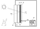
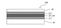
- FIG. 1 is a cross-sectional view schematically showing a usage pattern of the infrared reflective film.
- the infrared reflective film 100 of the present invention includes an infrared reflective layer 20 and a transparent protective layer 30 on a transparent film substrate 10.
- the infrared reflective film 100 is used by being placed on the indoor side of the window 50 of a building or an automobile, the transparent film substrate 10 side being bonded to the window 50 via an appropriate adhesive layer 60 or the like.
- the transparent protective layer 30 is disposed on the indoor side.
- the infrared reflective film 100 of the present invention transmits visible light (VIS) from the outside and introduces it into the room, and transmits near infrared (NIR) from the infrared reflective layer 20. Reflect on.
- the near-infrared reflection suppresses the inflow of heat from the outside due to sunlight or the like into the room (a heat shielding effect is exhibited), so that the cooling efficiency in summer can be improved.
- the infrared reflective layer 20 reflects indoor far infrared rays (FIR) radiated from the heating appliance 80 or the like, a heat insulating effect is exhibited, and heating efficiency in winter can be enhanced.
- FIR far infrared rays
- the infrared reflective film 100 includes an infrared reflective layer 20 and a transparent protective layer 30 in this order on one main surface of the transparent film substrate 10.
- the infrared reflective film 100 has no metal layer between the transparent film substrate 10 and the infrared reflective layer 20 and between the infrared reflective layer 20 and the transparent protective layer 30.
- the infrared reflective layer 20 includes a first metal oxide layer 21, a metal layer 25, and a second metal oxide layer 22 in this order from the transparent film substrate 10 side, and the first metal oxide layer 21 and the second metal oxide layer 22 are arranged in this order.
- Each of the physical layers 22 is in direct contact with the metal layer 25.
- the transparent protective layer 30 In order to reflect far infrared rays in the room by the infrared reflecting layer 20, it is important that the amount of far infrared rays absorbed by the transparent protective layer 30 is small. On the other hand, in order to prevent the infrared reflective layer 20 from being scratched or deteriorated, the transparent protective layer 30 is required to have mechanical strength and chemical strength.
- the infrared reflective film of the present invention can have all of transparency (visible light transmittance), heat shielding by near infrared reflection, heat insulation by far infrared reflection, and durability by having a predetermined laminated structure. .
- each layer which comprises an infrared reflective film is demonstrated sequentially.
- Transparent film substrate As the transparent film substrate 10, a flexible resin film having a visible light transmittance of 80% or more is preferably used. In the present specification, the visible light transmittance is measured according to JIS A5759: 2008 (architectural window glass film).
- the thickness of the transparent film substrate 10 is not particularly limited, but is, for example, about 10 ⁇ m to 300 ⁇ m. Since processing at high temperature may be performed when the infrared reflective layer 20 is formed on the transparent film substrate 10, the resin material constituting the transparent film substrate is preferably excellent in heat resistance. Examples of the resin material constituting the transparent film substrate include polyethylene terephthalate (PET), polyethylene naphthalate (PEN), polyetheretherketone (PEEK), and polycarbonate (PC).
- PET polyethylene terephthalate
- PEN polyethylene naphthalate
- PEEK polyetheretherketone
- PC polycarbonate
- a hard coat layer or the like may be provided on the surface of the transparent film substrate 10.
- corona treatment, plasma treatment, flame treatment, ozone treatment, primer treatment, glow treatment, Surface modification treatment such as saponification treatment or treatment with a coupling agent may be performed.
- the infrared reflection layer 20 transmits visible light and reflects near infrared rays and far infrared rays, and from the transparent film substrate 10 side, the first metal oxide layer 21, the metal layer 25, and the second metal oxide layer. 22 are provided in this order. Each of the first metal oxide layer 21 and the second metal oxide layer 22 is in direct contact with the metal layer 25, and the infrared reflective layer 20 is composed of these three layers.
- the metal layer 25 has a central role of infrared reflection.
- a silver alloy layer mainly composed of silver is used as a metal layer sandwiched between metal oxide layers from the viewpoint of increasing visible light transmittance and near infrared reflectance without increasing the number of layers.
- silver has a high free electron density, it can achieve high reflectivity of near infrared rays and far infrared rays, and is excellent in heat shielding effect and heat insulating effect even when the number of layers constituting the infrared reflection layer 20 is small.
- An infrared reflective film is obtained.
- the metal layer 25 preferably contains 96 to 99.9% by weight of silver.
- the silver content is more preferably 97% by weight or more, still more preferably 98% by weight or more, and particularly preferably 99% by weight or more.
- the visible light transmittance of the infrared reflective film tends to be increased.
- the metal layer 25 is preferably a silver alloy layer containing a metal other than silver for the purpose of improving durability.
- the silver content in the metal layer 25 is preferably 99.9% by weight or less, more preferably 99.8% by weight or less, and even more preferably 99.7% or less.
- the metal layer 25 preferably contains 0.1% by weight or more of a metal other than silver, more preferably 0.2% by weight or more, and more preferably 0.3% by weight or more. More preferably.
- a metal other than silver more preferably 0.2% by weight or more, and more preferably 0.3% by weight or more. More preferably.
- the metal added for the purpose of enhancing the durability of the metal layer palladium (Pd), gold (Au), copper (Cu), bismuth (Bi), germanium (Ge), gallium (Ga) and the like are preferable.
- Pd is most preferably used from the viewpoint of imparting high durability to silver. When the addition amount of Pd or the like is increased, the durability of the metal layer tends to be improved.
- the content of metals other than silver in the metal layer 25 is preferably 4% by weight or less, more preferably 3% by weight or less, further preferably 2% by weight or less, and particularly preferably 1% by weight or less.
- the metal oxide layers 21 and 22 are provided for the purpose of controlling the amount of visible light reflection at the interface with the metal layer 25 to achieve both high visible light transmittance and infrared reflectance.
- the metal oxide layer can also function as a protective layer for preventing the metal layer 25 from deteriorating.
- the refractive index of the metal oxide layers 21 and 22 with respect to visible light is preferably 1.5 or more, more preferably 1.6 or more, and 1.7 or more. Is more preferable.
- the material having the above refractive index examples include oxides of metals such as Ti, Zr, Hf, Nb, Zn, Al, Ga, In, Tl, and Sn, or composite oxides of these metals.
- a composite metal oxide containing zinc oxide is suitably used as the material for the first metal oxide layer 21 and the second metal oxide layer 22.
- These metal oxide layers are preferably amorphous.
- the metal oxide layer is an amorphous layer containing zinc oxide, the durability of the metal oxide layer itself is enhanced and the function as a protective layer for the metal layer is increased. 25 deterioration is suppressed.
- the content of zinc oxide in the metal oxide layers 21 and 22 is preferably 3 parts by weight or more, more preferably 5 parts by weight or more, and still more preferably 7 parts by weight or more with respect to 100 parts by weight of the total metal oxide. .
- the content of zinc oxide is in the above range, the metal oxide layer tends to be an amorphous layer, and the durability tends to be improved.
- the content of zinc oxide in the metal oxide layers 21 and 22 is preferably 60 parts by weight or less, more preferably 50 parts by weight or less, and 40 parts by weight or less with respect to 100 parts by weight of the total metal oxide. Further preferred.
- indium-zinc composite oxide (IZO) and zinc-tin composite oxide (ZTO) are used from the viewpoint of satisfying all of visible light transmittance, refractive index and durability.
- Indium-tin-zinc composite oxide (ITZO) is preferable.
- These composite oxides may further contain metals such as Al and Ga, and oxides of these metals.
- the thicknesses of the metal layer 25 and the metal oxide layers 21 and 22 are appropriately set in consideration of the refractive index of the material so that the infrared reflecting layer transmits visible light and selectively reflects near infrared light.
- the thickness of the metal layer 25 can be adjusted, for example, in the range of 5 nm to 50 nm, preferably 5 nm to 25 nm, more preferably 10 nm to 18 nm.
- the thickness of the metal oxide layers 21 and 22 can be adjusted, for example, in the range of 3 nm to 80 nm, preferably 3 nm to 50 nm, more preferably 3 nm to 35 nm.
- the method for forming the metal layer and the metal oxide layer is not particularly limited, but film formation by a dry process such as sputtering, vacuum evaporation, CVD, or electron beam evaporation is preferable.
- a transparent protective layer 30 is provided on the second metal oxide layer 22 of the infrared reflective layer 20 for the purpose of preventing scratches and deterioration of the metal oxide layers 21 and 22 and the metal layer 25. From the viewpoint of forming the transparent protective layer within the range of the heat resistant temperature of the film substrate, an organic substance is used as the material of the transparent protective layer. In addition, the transparent protective layer should just mainly consist of organic substance, and the inorganic filler etc. may be added.
- the transparent protective layer 30 preferably has a low visible light absorption in addition to having a high visible light transmittance.
- the far-infrared absorptance is large, indoor far-infrared rays are absorbed by the transparent protective layer and are radiated to the outside by heat conduction, so that the heat insulating property of the infrared reflecting film tends to be lowered.
- the far-infrared absorption by the transparent protective layer 30 is small, the far-infrared is reflected indoors by the metal layer 25 of the infrared reflection layer 20, so that the heat insulation effect of the infrared reflection film is enhanced.
- Examples of a method for reducing the far-infrared absorption amount by the transparent protective layer 30 include a method for reducing the thickness of the transparent protective layer, and a method using a material having a low far-infrared absorption as the material for the transparent protective layer.
- the thickness of the transparent protective layer is preferably 300 nm or less, more preferably 200 nm or less, and even more preferably 100 nm or less.
- the thickness of the transparent protective layer is small, the heat insulating effect can be enhanced by reducing the far-infrared absorption, while the function as a protective layer for enhancing the durability of the infrared reflective layer may be reduced. Therefore, when the thickness of the transparent protective layer is 200 nm or less, it is preferable that a material having excellent strength is used as the transparent protective layer and that the durability of the infrared reflective layer itself is enhanced.
- the content of components such as palladium is increased by decreasing the silver content in the metal layer 25.
- the metal layer 25 is an alloy of silver and palladium
- the silver: palladium content is preferably adjusted to about 96: 4 to 98: 2 by weight.
- the far-infrared absorption can be kept small even if the thickness of the protective layer is increased. be able to. According to this configuration, since the durability of the infrared reflective film can be increased without excessively increasing the content of palladium or the like in the metal layer 25, it is possible to improve both the visible light transmittance and the durability. preferable.
- a material for the transparent protective layer a compound having a small content such as a C ⁇ C bond, a C ⁇ O bond, a C—O bond or an aromatic ring is preferably used from the viewpoint of reducing far-infrared absorption.
- polyolefins such as polyethylene and polypropylene, alicyclic polymers such as cycloolefin polymers, rubber polymers, and the like are preferably used.
- the material constituting the transparent protective layer a material having a high visible light transmittance, an excellent adhesion to the infrared reflective layer, and an excellent scratch resistance in addition to a low far infrared absorptivity is suitably used.
- rubber-based materials are particularly preferable, and nitrile rubber-based materials are particularly preferably used.
- the nitrile rubber-based material has a structure represented by the following formulas (A), (B), and (C) in the molecule.
- R 1 is hydrogen or a methyl group
- R 2 to R 5 are each independently hydrogen, a linear or branched alkyl group having 1 to 4 carbon atoms, or A straight-chain or branched alkenyl group having 1 to 4 carbon atoms.
- nitrile rubber in which R 1 to R 5 are all hydrogen in the above formulas (A) to (C) is excellent in transparency and durability, and is suitable as a material for the transparent protective layer.
- Nitrile rubber is obtained, for example, by copolymerizing acrylonitrile and / or a derivative thereof and 1,3-butadiene.
- HNBR hydrogenated nitrile rubber
- hydrogenated hydrogenated nitrile rubber
- the double bond is hydrogenated, the far-infrared absorptivity decreases, so that the far-infrared absorption amount of the transparent protective layer decreases, and the heat insulating property of the infrared radiation film can be enhanced.
- the ratio of k: l: m (molar ratio) is more preferably in the range of 5-25: 60-90: 0-20, and still more preferably in the range of 15-25: 65-85: 0-10.
- the transparent protective layer 30 has an indentation hardness of 1.2 MPa or more from the viewpoint of enhancing the scratch resistance of the infrared reflective film and ensuring a protective function for the infrared reflective layer. Preferably, it is 1.5 MPa or more, more preferably 2 MPa or more.
- the indentation hardness can be within the above range by introducing a crosslinked structure into the polymer.
- the solvent resistance of the transparent protective layer can be improved by introducing a crosslinked structure.
- the indentation hardness of the transparent protective layer is measured by an indentation test using a micro hardness tester.
- the indenter indentation load P and the projected area (projected contact area) A of the contact area between the indenter and the protective layer are measured in a state where the indenter is pushed into the protective layer to a predetermined indentation depth.
- the projected contact area A can be measured by the method disclosed in JP-A-2005-195357.
- the cross-linked structure is introduced, for example, by applying a polymer solution such as hydrogenated nitrile rubber on a substrate, and irradiating with electron beam after drying.
- the cumulative irradiation amount of the electron beam for introducing the crosslinked structure is preferably about 50 kGy to 1000 kGy, more preferably about 100 kGy to 600 kGy, and further preferably about 200 kGy to 400 kGy. If the integrated irradiation amount of the electron beam is within the above range, a sufficient cross-linked structure is introduced between the polymer chains, and yellowing of the transparent protective layer 30 and the transparent film substrate 10 is suppressed, so that the durability and visibility are improved. An infrared reflecting film having excellent light transmittance is easily obtained.
- a radically polymerizable polyfunctional monomer such as a polyfunctional (meth) acrylic monomer
- a sufficient cross-linked structure can be introduced between the polymer chains even with a low integrated dose of about 50 kGy. .
- a crosslinking agent may be used.
- the crosslinking agent radically polymerizable polyfunctional monomers are preferably used, and in particular, polyfunctional (meth) acrylic monomers are preferably used.
- the polyfunctional (meth) acrylic monomer used as a crosslinking agent include trimethylolpropane tri (meth) acrylate, tris (acryloxyethyl) isocyanurate, ditrimethylolpropane tetra (meth) acrylate, pentaerythritol tetra (meth). ) Acrylate, dipentaerythritol penta (meth) acrylate, dipentaerythritol hexa (meth) acrylate, and the like.
- the addition amount is preferably about 1 to 35 parts by weight and more preferably about 2 to 25 parts by weight with respect to 100 parts by weight of the polymer. If the content of the crosslinking agent is excessively small, the durability may not be sufficiently improved. On the other hand, when the content of the crosslinking agent is excessively large, the amount of far infrared rays absorbed is increased, and the amount of far infrared rays absorbed by the transparent protective layer is increased.
- the method for forming the transparent protective layer is not particularly limited.
- a polymer such as hydrogenated nitrile rubber is dissolved in a solvent together with a crosslinking agent as necessary to prepare a solution, and this solution is placed on the infrared reflective layer 20. After coating, it is formed by drying the solvent.
- the solvent is not particularly limited as long as it can dissolve the polymer, but a low boiling point solvent such as methyl ethyl ketone (MEK) or methylene chloride is preferably used.
- MEK methyl ethyl ketone
- the solution can be dried on the infrared reflecting layer 20 and dried at a low temperature. In addition, thermal damage to the infrared reflective layer 20 and the transparent film substrate 10 is suppressed.
- a low boiling point solvent such as methyl ethyl ketone (boiling point: 79.5 ° C.) or methylene chloride (boiling point: 40 ° C.
- the material of the transparent protective layer 30 includes a coupling agent such as a silane coupling agent and a titanium coupling agent, a leveling agent, an ultraviolet absorber, an antioxidant, a heat stabilizer lubricant, a plasticizer, and a coloring agent.
- a coupling agent such as a silane coupling agent and a titanium coupling agent
- a leveling agent such as an ultraviolet absorber, an antioxidant, a heat stabilizer lubricant, a plasticizer, and a coloring agent.
- Additives such as an inhibitor, a flame retardant, and an antistatic agent may be included.
- the content of these additives can be appropriately adjusted within a range that does not impair the object of the present invention, but the content of the polymer in the transparent protective layer is preferably 80% by weight or more.
- the content of the hydrogenated nitrile rubber in the transparent protective layer is preferably 90% by weight or more, more preferably 95% by weight or more, and 99% by weight. The above is more preferable.
- the thickness of the transparent protective layer is preferably 1 ⁇ m to 20 ⁇ m, more preferably 2 ⁇ m to 15 ⁇ m, and more preferably 3 ⁇ m to 10 ⁇ m. Further preferred. If the thickness of the transparent protective layer is in the above range, the protective layer itself has sufficient physical strength, and the protective function of the infrared reflecting layer can be enhanced, and the amount of far infrared rays absorbed can be reduced.
- the infrared reflective film 100 of the present invention is an infrared reflective layer comprising the first metal oxide layer 21, the metal layer 25, and the second metal oxide layer 22 on one main surface of the transparent film substrate 10. 20 and a transparent protective layer 30. Between the transparent film substrate 10 and the infrared reflective layer 20 and between the infrared reflective layer 20 and the transparent protective layer 30, for the purpose of increasing the adhesion of each layer, the purpose of increasing the strength of the infrared reflective film, and the like.
- a hard coat layer, an easily adhesive layer, and the like may be provided. There are no particular restrictions on the material and formation method of the easy-adhesion layer and hard coat layer, but a transparent material having a high visible light transmittance is preferably used.
- the infrared reflective layer 20 has a three-layer configuration of the first metal oxide layer 21 / the metal layer 25 / the second metal oxide layer 22, and the transparent film substrate 10 and the infrared reflective layer 20. And between the infrared reflective layer 20 and the transparent protective layer 30, none of them has a metal layer. With this configuration, productivity can be improved and manufacturing costs can be reduced.
- the metal oxide layer, the metal layer, and the transparent protective layer materials in a predetermined combination, even if the infrared reflection layer has a three-layer structure, a high visible light transmittance (high transparency) ), A low shielding coefficient (high heat shielding property), a low emissivity (high heat insulating property), and a high durability.
- the surface of the transparent film substrate 10 opposite to the infrared reflective layer 20 may be provided with an adhesive layer or the like for use in bonding the infrared reflective film and window glass or the like.
- an adhesive layer those having a high visible light transmittance and a small refractive index difference from the transparent film substrate 10 are preferably used.
- an acrylic pressure-sensitive adhesive pressure-sensitive adhesive
- the adhesive layer preferably has a high visible light transmittance and a low ultraviolet transmittance.
- the adhesive layer By reducing the ultraviolet transmittance of the adhesive layer, it is possible to suppress the deterioration of the infrared reflecting layer due to ultraviolet rays such as sunlight.
- the adhesive layer preferably contains an ultraviolet absorber.
- deterioration of the infrared reflective layer resulting from the ultraviolet rays from the outdoors can also be suppressed by using a transparent film substrate containing an ultraviolet absorber.
- the exposed surface of the adhesive layer is preferably covered with a separator temporarily for the purpose of preventing contamination of the exposed surface until the infrared reflective film is put to practical use. Thereby, the contamination by the contact with the exterior of the exposed surface of an adhesive bond layer can be prevented in the usual handling state.
- the visible light transmittance of the infrared reflective film of the present invention is preferably 65% or more, more preferably 68% or more, and further preferably 70% or more.
- the shielding coefficient of the infrared reflective film is preferably less than 0.60, more preferably 0.59 or less, further preferably 0.58 or less, and particularly preferably 0.57 or less.
- the corrected emissivity measured from the transparent protective layer 30 side of the infrared reflective film is preferably 0.20 or less, more preferably 0.18 or less, and even more preferably 0.16 or less.
- a correction emissivity is measured according to JlS R3107: 1998 (The calculation method of the thermal resistance of plate glass, and the heat transmissivity in a building).
- the change in the corrected emissivity after the infrared reflective film is immersed in a 5 wt% sodium chloride aqueous solution at 50 ° C. for 5 days is preferably 0.05 or less, more preferably 0.03 or less, and even more preferably 0.02 or less. .
- these characteristics are achieved by appropriately selecting the material of each layer constituting the infrared reflective film.
- the infrared reflective film of the present invention is preferably used in order to adhere to windows of buildings and vehicles, transparent cases into which plants are placed, frozen or refrigerated showcases, etc., and to improve the heating / cooling effect and prevent rapid temperature changes.
- each layer constituting the infrared reflecting layer is determined by processing a sample by a focused ion beam (FIB) method using a focused ion beam processing observation apparatus (product name “FB-2100” manufactured by Hitachi, Ltd.) They were obtained by observation with a field emission transmission electron microscope (product name “HF-2000”, manufactured by Hitachi, Ltd.).
- the thickness of the hard coat layer formed on the substrate and the transparent protective layer is visible light when light is incident from the measuring object side using an instantaneous multi-photometry system (product name “MCPD3000” manufactured by Otsuka Electronics). It calculated
- the visible light transmittance was determined according to JIS A5759-2008 (architectural window glass film) using a spectrophotometer (product name “U-4100” manufactured by Hitachi High-Tech).
- ⁇ Shielding coefficient> Using a spectrophotometer (product name “U-4100” manufactured by Hitachi High-Technologies), the solar transmittance ⁇ e and the solar reflectance ⁇ e are measured, and the shielding coefficient is determined by the JIS A5759-2008 (architectural window glass film) A method. Was calculated.
- the modified emissivity is infrared light having a wavelength of 5 ⁇ m to 25 ⁇ m when infrared light is irradiated from the protective layer side using a Fourier transform infrared spectroscopic (FT-IR) apparatus (manufactured by Varian) equipped with a variable angle reflection accessory.
- FT-IR Fourier transform infrared spectroscopic
- ⁇ Abrasion resistance test> A sample obtained by bonding the surface of the infrared reflective film on the transparent film substrate side to an aluminum plate via a 25 ⁇ m thick adhesive layer was used as a sample. Using a Gakushin Abrasion Tester, the surface of the infrared reflective film on the aluminum plate on the transparent protective layer side was rubbed 1000 times while applying a load of 500 g with a test cotton cloth (Kanakin No. 3). The sample after the test was visually evaluated for scratches and peeling on the protective layer, and evaluated according to the following evaluation criteria. Good: No scratches on the surface, or fine scratches but no peeling. Bad: Many scratches or peeling on the surface.
- ⁇ Salt water resistance test> A sample obtained by bonding the surface of the infrared reflective film on the transparent film substrate side to a 3 cm ⁇ 3 cm glass plate via a 25 ⁇ m thick adhesive layer was used as a sample. This sample is immersed in a 5% by weight sodium chloride aqueous solution, and the container containing the sample and the sodium chloride aqueous solution is placed in a dryer at 50 ° C. After 5 days, changes in emissivity and appearance are confirmed, and the following evaluations are made. Evaluation was made according to criteria. Good: No change in appearance after immersion for 5 days and change in emissivity of 0.05 or less Poor: Change in appearance is confirmed after immersion for 5 days, change in emissivity is 0.05 or more
- Example 1 (Formation of infrared reflective layer) A polyethylene terephthalate film having a thickness of 50 ⁇ m (trade name “Lumirror U48” manufactured by Toray Industries, Inc., 93% visible light transmittance) was used as a transparent film substrate. An infrared reflective layer was formed on one surface of the substrate using a winding type sputtering apparatus. Specifically, by DC magnetron sputtering, a first metal oxide layer made of indium-zinc composite oxide (IZO) with a thickness of 30 nm, a metal layer made of Ag—Pd alloy with a thickness of 15 nm, and a film thickness of 30 nm made of IZO. The second metal oxide layers were sequentially formed.
- IZO indium-zinc composite oxide
- an oxide target obtained by sintering indium oxide and zinc oxide at a weight ratio of 90:10 is used.
- Ar gas / O 2 gas introduction amount: Sputtering was performed under the conditions of 300 sccm / 3 sccm and process pressure: 0.4 Pa.
- a metal target containing silver: palladium in a weight ratio of 99.5: 0.5 was used.
- HNBR hydrogenated nitrile rubber
- the surface of the infrared reflective film on the transparent film substrate side was bonded to a 1.5 cm ⁇ 1.5 cm slide glass through an adhesive layer to prepare an indentation test sample.
- the test sample was fixed on the stage of an observation type micromaterial evaluation system (manufactured by Mihiro, product name “Microindent Scope MIS-2000”) so that the transparent protective layer side of the test sample was the surface side. From the surface of the transparent protective layer, the indentation load and the contact projected area of the indenter were determined in a state where the Barkovic diamond indenter was indented at an indentation speed of 0.1 ⁇ m / second until the indentation depth reached 3 ⁇ m.
- the indentation hardness H of the transparent protective layer before electron beam irradiation was measured by the same test method, it was 1.2 MPa.
- Example 2 Example 1 except that a 30 nm-thick metal oxide layer made of zinc-tin composite oxide (ZTO) was formed as the first metal oxide layer and the second metal oxide layer instead of IZO. In the same manner, an infrared reflective film was produced.
- ZTO metal oxide layer a metal-containing oxide target obtained by sintering zinc oxide, tin oxide and metal zinc powder at a weight ratio of 10: 82.5: 7.5 is used, and the power density : Sputtering was performed under the conditions of 4 W / cm 2 , Ar gas / O 2 gas introduction amount: 300 sccm / 3 sccm, and process pressure: 0.4 Pa.
- Example 3 (Formation of hard coat layer on substrate) A 50 ⁇ m thick polyethylene terephthalate film (trade name “Lumirror U48” manufactured by Toray, 93% visible light transmittance) has a thickness of 2 ⁇ m on an acrylic UV curable hard coat layer (Nippon Soda, NH2000G). Formed with. Specifically, a hard coat solution was applied by a gravure coater, dried at 80 ° C., and then irradiated with ultraviolet light with an integrated light amount of 300 mJ / cm 2 by an ultrahigh pressure mercury lamp to be cured.
- infrared reflective layer An infrared reflective layer was formed on the hard coat layer of the polyethylene terephthalate film substrate using a winding type sputtering apparatus. Specifically, by DC magnetron sputtering, a 30 nm-thick first metal oxide layer made of zinc-tin composite oxide (ZTO), a 15 nm-thick metal layer made of an Ag—Pd alloy, and a 30 nm-thickness made of ZTO. The second metal oxide layers were sequentially formed. The formation of the ZTO metal oxide layer was performed under the same conditions as in Example 2. For the formation of the metal layer, a metal target containing silver: palladium in a weight ratio of 97: 3 was used.
- ZTO zinc-tin composite oxide
- a protective layer made of a fluorine-based ultraviolet curable resin was formed with a thickness of 30 nm on the infrared reflective layer. Specifically, 5 parts by weight of a phosphoric acid ester compound (manufactured by Nippon Kayaku, trade name “KAYAMER PM-21”) was added to 100 parts by weight of the solid content of the fluorine-based hard coat resin solution (manufactured by JSR, JUA204). The solution was applied using an applicator, dried at 60 ° C. for 1 minute, and then cured by irradiating an ultraviolet ray with an integrated light amount of 400 mJ / cm 2 with an ultrahigh pressure mercury lamp in a nitrogen atmosphere.
- a phosphoric acid ester compound manufactured by Nippon Kayaku, trade name “KAYAMER PM-21”
- Example 1 An infrared reflective film was produced in the same manner as in Example 1, except that a metal target containing silver: palladium in a weight ratio of 95: 5 was used for forming the metal layer.
- Example 2 An infrared reflective film was produced in the same manner as in Example 1 except that a metal target made of silver was used for forming the metal layer.
- Example 3 An infrared reflective film was produced in the same manner as in Example 1 except that an acrylic hard coat layer having a thickness of 4 ⁇ m was formed as the transparent protective layer.
- the acrylic hard coat layer is coated with an acrylic hard coat solution (product name “PC1097” manufactured by DIC) on the infrared reflective layer with a gravure coater, dried at 80 ° C. for 2 minutes, and then integrated with an ultrahigh pressure mercury lamp. It was formed by irradiating ultraviolet rays of 400 mJ / cm 2 .
- Example 4 An infrared reflective film was formed in the same manner as in Example 1 except that a metal target containing silver: copper at a weight ratio of 90:10 was used for forming the metal layer.
- Example 5 An infrared reflective film was formed in the same manner as in Example 1 except that the transparent protective layer was not formed on the infrared reflective layer.
- Example 6 An infrared reflective film was produced in the same manner as in Example 3 except that a zinc oxide target was used to form the first metal oxide layer and the second metal oxide layer.
- Example 7 A metal-containing oxide target obtained by sintering indium oxide and tin oxide at a weight ratio of 90:10 is used for forming the first metal oxide layer and the second metal oxide layer.
- An infrared reflective film was produced in the same manner as in Example 3 except that the thickness of the layer was changed to 40 nm.
- a metal containing nickel and chromium in a weight ratio of 80:20 between the first metal oxide layer and the metal layer and between the metal layer and the second metal oxide layer in forming the infrared reflective layer A Ni—Cr alloy layer is formed with a film thickness of 3 nm by sputtering using a target, and an infrared reflection layer has a five-layer structure of ITO / Ni—Cr / Ag—Pd / Ni—Cr / ITO. It was done. Other than that was carried out similarly to the comparative example 7, and produced the infrared reflective film.
- Example 9 An infrared reflective film was produced in the same manner as in Example 2 except that the thickness of the transparent protective layer was changed to 20 ⁇ m.
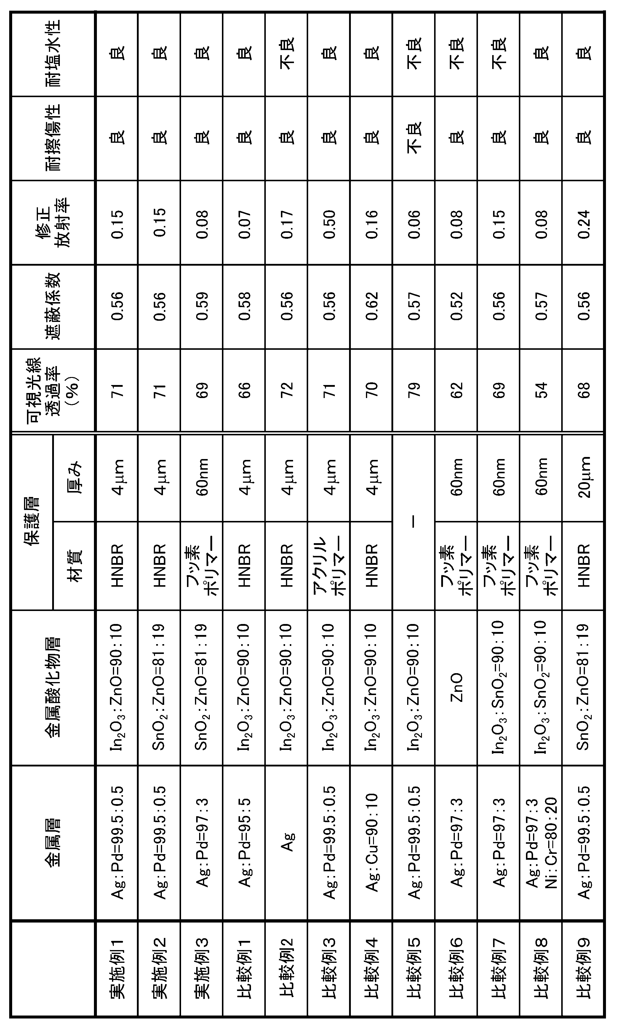
- Table 1 shows the evaluation results of the infrared reflective films of the above Examples and Comparative Examples.
- all the compositions of the metal layer and the metal oxide layer in Table 1 are weight ratios.
- Comparative Example 1 In Comparative Example 1 in which the Ag content in the metal layer was small, a decrease in visible light transmittance was observed. On the other hand, in Comparative Example 2 in which the metal layer was made of pure silver, a decrease in durability was observed.
- Comparative Example 3 in which an acrylic hard coat layer was used as a material for the transparent protective layer, an increase in emissivity was observed. This is presumably because the acrylic resin has many C ⁇ O bonds in the molecule and has a large amount of absorption of far infrared rays.
- Comparative Example 9 hydrogenated nitrile rubber was used as the material for the transparent protective layer. However, since the thickness was as large as 20 ⁇ m, the amount of far-infrared absorbed increased and the emissivity increased.
- Comparative Example 5 in which the transparent protective layer was not formed, since far-infrared absorption by the protective layer did not occur, the emissivity was small, but the durability was poor.
- Comparative Example 4 in which a silver and copper alloy layer was used as the metal layer, although the visible light transmittance was high, an increase in the shielding coefficient (decrease in heat shielding properties) was observed. This is presumed to be due to the low transmittance of both visible light and near infrared light due to the low silver content, which makes it impossible to give the wavelength selectivity appropriate for the reflectance of the infrared reflective layer.
- Comparative Example 8 in which a three-layer metal layer in which an Ag—Pd alloy layer was sandwiched between Nr—Cr alloy layers was used, a decrease in visible light transmittance was observed.
- Comparative Example 7 In Comparative Example 7 in which ITO was used as the metal oxide layer, the visible light transmittance was low, and the durability of the infrared absorption layer was insufficient. On the other hand, in Comparative Example 7 in which zinc oxide was used as the metal oxide layer, the visible light transmittance and durability were lowered. From these results, in order to form an infrared reflective layer having high visible light transmittance and excellent durability, it is preferable to use a composite oxide containing zinc oxide as the metal oxide material. .
- the infrared reflective films of Examples 1 to 4 all had high visible light transmittance and shielding coefficient, low emissivity, and excellent durability. Among them, Examples 1 and 2 in which hydrogenated nitrile rubber was used for the transparent protective layer showed high visible light transmittance exceeding 70%.
Abstract
Description
図2に示すように、赤外線反射フィルム100は、透明フィルム基材10の一主面上に、赤外線反射層20および透明保護層30をこの順に備える。赤外線反射フィルム100は、透明フィルム基材10と赤外線反射層20との間、および赤外線反射層20と透明保護層30との間には、いずれも金属層を有していない。赤外線反射層20は、透明フィルム基材10側から、第一金属酸化物層21、金属層25および第二金属酸化物層22をこの順に備え、第一金属酸化物層21および第二金属酸化物層22のそれぞれは、金属層25に直接接している。
透明フィルム基材10としては、可視光線透過率が80%以上である可撓性の樹脂フィルムが好適に用いられる。なお、本明細書において、可視光線透過率は、JIS A5759:2008(建築窓ガラスフィルム)に準じて測定される。
赤外線反射層20は、可視光を透過し、近赤外線および遠赤外線を反射するものであり、透明フィルム基材10側から、第一金属酸化物層21、金属層25および第二金属酸化物層22をこの順に備える。また、第一金属酸化物層21および第二金属酸化物層22のそれぞれは、金属層25に直接接しており、赤外線反射層20はこれらの3層からなる。
金属層25は、赤外線反射の中心的な役割を有する。本発明においては、積層数を増加させることなく、可視光線透過率と近赤外線反射率を高める観点から、金属酸化物層の間に挟持される金属層として、銀を主成分とする銀合金層が好適に用いられる。銀は高い自由電子密度を有するため、近赤外線・遠赤外線の高い反射率を実現することができ、赤外線反射層20を構成する層の積層数が少ない場合でも、遮熱効果および断熱効果に優れる赤外線反射フィルムが得られる。
金属酸化物層21,22は、金属層25との界面における可視光線の反射量を制御して、高い可視光線透過率と、赤外線反射率とを両立させる等の目的で設けられる。また、金属酸化物層は、金属層25の劣化を防止するための保護層としても機能し得る。赤外線反射層における反射および透過の波長選択性を高める観点から、金属酸化物層21,22の可視光に対する屈折率は、1.5以上が好ましく、1.6以上がより好ましく、1.7以上がさらに好ましい。
赤外線反射層20の第二金属酸化物層22上には、金属酸化物層21,22や金属層25の擦傷や劣化を防止する目的で、透明保護層30が設けられる。フィルム基材の耐熱温度の範囲内で透明保護層を形成する観点から、透明保護層の材料としては有機物が用いられる。なお、透明保護層は主に有機物からなるものであればよく、無機フィラー等が添加されたものでもよい。

上記のように、本発明の赤外線反射フィルム100は、透明フィルム基材10の一主面上に、第一金属酸化物層21、金属層25および第二金属酸化物層22からなる赤外線反射層20、ならびに透明保護層30を有する。透明フィルム基材10と赤外線反射層20との間、および赤外線反射層20と透明保護層30との間には、各層の密着性を高める目的や、赤外線反射フィルムの強度を高める等の目的で、ハードコート層や易接着層等が設けられていてもよい。易接着層やハードコート層等の材料や形成方法は特に限定されないが、可視光線透過率の高い透明な材料が好適に用いられる。
本発明の赤外線反射フィルムの可視光透過率は、65%以上が好ましく、68%以上がより好ましく、70%以上がさらに好ましい。赤外線反射フィルムの遮蔽係数は、0.60未満が好ましく、0.59以下がより好ましく、0.58以下がさらに好ましく、0.57以下が特に好ましい。赤外線反射フィルムの透明保護層30側から測定した修正放射率は、0.20以下が好ましく、0.18以下がより好ましく、0.16以下がさらに好ましい。なお、本明細書において、修正放射率は、JlS R3107:1998(板ガラス類の熱抵抗及び建築における熱貫流率の算定方法)に準じて測定される。赤外線反射フィルムが50℃の5重量%塩化ナトリウム水溶液に5日間浸漬された後の修正放射率の変化は、0.05以下が好ましく、0.03以下がより好ましく、0.02以下がさらに好ましい。これらの特性は、上述のように、赤外線反射フィルムを構成する各層の材料等を適切に選択することによって達成される。
本発明の赤外線反射フィルムは、建物や乗り物等の窓、植物等を入れる透明ケース、冷凍もしくは冷蔵のショーケース等に貼着し、冷暖房効果の向上や急激な温度変化を防ぐために、好ましく使用される。
<各層の厚み>
赤外線反射層を構成する各層の厚みは、集束イオンビーム加工観察装置(日立製作所製、製品名「FB-2100」)を用いて、集束イオンビーム(FIB)法により試料を加工し、その断面を、電界放出形透過電子顕微鏡(日立製作所製、製品名「HF-2000」)により観察して求めた。基材上に形成されたハードコート層、および透明保護層の厚みは、瞬間マルチ測光システム(大塚電子製、製品名「MCPD3000」)を用い、測定対象側から光を入射させた際の可視光の反射光の干渉パターンから、計算により求めた。
可視光線透過率は、分光光度計(日立ハイテク製 製品名「U-4100」)を用いて、JIS A5759-2008(建築窓ガラスフィルム)に準じて求めた。
分光光度計(日立ハイテク製 製品名「U-4100」)を用いて、日射透過率τeおよび日射反射率ρeを測定し、JIS A5759-2008(建築窓ガラスフィルム)A法により、遮蔽係数を算出した。
修正放射率は、角度可変反射アクセサリを備えるフーリエ変換型赤外分光(FT-IR)装置(Varian製)を用いて、保護層側から赤外線を照射した場合の、波長5μm~25μmの赤外光の正反射率を測定し、JIS R3107:1998(板ガラス類の熱抵抗及び建築における熱貫流率の算定方法)に準じて求めた。
赤外線反射フィルムの透明フィルム基材側の面を、厚み25μmの粘着剤層を介してアルミ板に貼り合せたものを試料として用いた。学振摩耗試験機を用いて、試験用綿布(かなきん3号)で500gの荷重を加えながら、アルミ板上の赤外線反射フィルムの透明保護層側の面を1000往復擦った。試験後の試料の保護層への傷、剥離の有無を目視で評価し、以下の評価基準に従い、評価した。
良:表面に傷が認められないもの、および細い傷が認められるが剥離は生じていないもの
不良:表面に多数の傷や剥離が認められるもの
赤外線反射フィルムの透明フィルム基材側の面を、厚み25μmの粘着剤層を介して3cm×3cmのガラス板に貼り合せたものを試料として用いた。この試料を5重量%の塩化ナトリウム水溶液に浸漬し、試料および塩化ナトリウム水溶液が入った容器を50℃の乾燥機に入れ、5日後に放射率の変化および外観の変化を確認し、以下の評価基準に従って評価した。
良:5日間浸漬後も外観変化なく、かつ放射率の変化が0.05以下であるもの
不良:5日間浸漬後に、外観の変化が確認され、放射率の変化が0.05以上であるもの
(赤外線反射層の形成)
厚み50μmのポリエチレンテレフタレートフィルム(東レ製 商品名「ルミラー U48」、可視光透過率93%)を透明フィルム基材として用いた。この基材の一方の面に、巻取式スパッタ装置を用いて、赤外線反射層が形成された。詳しくは、DCマグネトロンスパッタ法により、インジウム-亜鉛複合酸化物(IZO)からなる膜厚30nmの第一金属酸化物層、Ag-Pd合金からなる膜厚15nmの金属層、IZOからなる膜厚30nmの第二金属酸化物層が順次形成された。金属酸化物層の形成には、酸化インジウムと酸化亜鉛を90:10の重量比で焼結させた酸化物ターゲットが用いられ、電力密度:4W/cm2、Arガス/O2ガス導入量:300sccm/3sccm、プロセス圧力:0.4Paの条件でスパッタが行われた。金属層の形成には、銀:パラジウムを99.5:0.5の重量比で含有する金属ターゲットが用いられた。
赤外線反射層上に、水素化ニトリルゴム(HNBR)からなる保護層が4μmの厚みで形成された。詳しくは、アクリロニトリルと1,3-ブタジエンの共重合体が水素化された水素化ブタジエンゴム(k:l:m=20.8:74.5:4.7)10重量部を90重量部のメチルエチルケトンに溶解したものを塗布液として用いた。この塗布液がアプリケーターを用いて赤外線反射上に塗布され、120℃で4分間乾燥後、窒素雰囲気下で、加速電圧125kV、積算照射量100kGyの電子線が照射され、架橋が行われた。
赤外線反射フィルムの透明フィルム基材側の面を、接着剤層を介して1.5cm×1.5cmのスライドガラスに貼り合せて、インデンテーション試験用試料を作製した。この試験用試料の透明保護層側が表面側となるように、観察式微小材料評価システム(三弘製、製品名「マイクロインデントスコープ MIS-2000」)のステージ上に固定した。透明保護層表面側から、バーコビッチ型のダイヤモンド製圧子を、押し込み速度0.1μm/秒で、押し込み深さが3μmになるまで押し込んだ状態での押し込み荷重と、圧子の接触投影面積を求めた。この測定によって求められた押し込み荷重Pと接触投影面積Aから、式:H=P/Aに基づいて算出された透明保護層表面の押し込み硬度Hは、3.5MPaであった。なお、電子線照射前の透明保護層の押し込み硬度Hを同様の試験法により測定したところ、1.2MPaであった。
第一金属酸化物層および第二金属酸化物層として、IZOに代えて、亜鉛-錫複合酸化物(ZTO)からなる膜厚30nmの金属酸化物層が形成されたこと以外は、実施例1と同様にして赤外線反射フィルムが作製された。ZTO金属酸化物層の形成には、酸化亜鉛と酸化錫と金属亜鉛粉末とを、10:82.5:7.5の重量比で焼結させた金属含有酸化物ターゲットが用いられ、電力密度:4W/cm2、Arガス/O2ガス導入量:300sccm/3sccm、プロセス圧力:0.4Paの条件でスパッタが行われた。
(基材へのハードコート層の形成)
厚みが50μmのポリエチレンテレフタレートフィルム(東レ製 商品名「ルミラー U48」、可視光透過率93%)の一方の面に、アクリル系の紫外線硬化型ハードコート層(日本曹達製、NH2000G)が2μmの厚みで形成された。詳しくは、グラビアコーターにより、ハードコート溶液が塗布され、80℃で乾燥後、超高圧水銀ランプにより積算光量300mJ/cm2の紫外線が照射され、硬化が行われた。
ポリエチレンテレフタレートフィルム基材のハードコート層上に、巻取式スパッタ装置を用いて、赤外線反射層が形成された。詳しくは、DCマグネトロンスパッタ法により、亜鉛-錫複合酸化物(ZTO)からなる膜厚30nmの第一金属酸化物層、Ag-Pd合金からなる膜厚15nmの金属層、ZTOからなる膜厚30nmの第二金属酸化物層が順次形成された。ZTO金属酸化物層の形成は、実施例2と同様の条件で行われた。金属層の形成には、銀:パラジウムを97:3の重量比で含有する金属ターゲットが用いられた。
赤外線反射層上に、フッ素系の紫外線硬化型樹脂からなる保護層が30nmの厚みで形成された。詳しくは、フッ素系ハードコート樹脂溶液(JSR製、JUA204)の固形分100重量部に対して、リン酸エステル化合物(日本化薬製、商品名「KAYAMER PM-21」)を5重量部添加した溶液を、アプリケーターを用いて塗布し、60℃で1分間乾燥後、窒素雰囲気下で超高圧水銀ランプにより積算光量400mJ/cm2の紫外線が照射され、硬化が行われた。
金属層の形成に、銀:パラジウムを95:5の重量比で含有する金属ターゲットが用いられたこと以外は、実施例1と同様にして赤外線反射フィルムが作製された。
金属層の形成に、銀からなる金属ターゲットが用いられたこと以外は、実施例1と同様にして赤外線反射フィルムが作製された。
透明保護層として、厚み4μmのアクリル系ハードコート層が形成されたこと以外は、実施例1と同様にして赤外線反射フィルムが作製された。アクリル系ハードコート層は、グラビアコーターにより、赤外線反射層上にアクリル系のハードコート溶液(DIC製 商品名「PC1097」)を塗布し、80℃で2分間乾燥後、超高圧水銀ランプにより積算光量400mJ/cm2の紫外線を照射することにより形成された。
金属層の形成に、銀:銅を90:10の重量比で含有する金属ターゲットが用いられたこと以外は、実施例1と同様にして赤外線反射フィルムが形成された。
赤外線反射層上に透明保護層が形成されなかったこと以外は、実施例1と同様にして赤外線反射フィルムが形成された。
第一金属酸化物層および第二金属酸化物層の形成に、酸化亜鉛ターゲットが用いられたこと以外は、実施例3と同様にして赤外線反射フィルムが作製された。
第一金属酸化物層および第二金属酸化物層の形成に、酸化インジウムと酸化錫とを、90:10の重量比で焼結させた金属含有酸化物ターゲットが用いられ、これらの金属酸化物層の製膜厚みが40nmに変更されたこと以外は、実施例3と同様にして赤外線反射フィルムが作製された。
赤外線反射層の形成において、第一金属酸化物層と金属層との間、および金属層と第二金属酸化物層との間に、ニッケルとクロムとを80:20の重量比で含有する金属ターゲットを用いたスパッタ法により、Ni-Cr合金層が、それぞれ3nmの膜厚で製膜され、赤外線反射層が、ITO/Ni-Cr/Ag-Pd/Ni-Cr/ITOの5層構成とされた。それ以外は、比較例7と同様にして赤外線反射フィルムが作製された。
透明保護層の厚みが20μmに変更されたこと以外は、実施例2と同様にして赤外線反射フィルムが作製された。
10: 透明フィルム基材
20: 赤外線反射層
21,22: 金属酸化物層
25: 金属層
30: 保護層
60: 接着剤層
Claims (6)
- 透明フィルム基材上に、赤外線反射層および透明保護層をこの順に備える赤外線反射フィルムであって、可視光透過率が65%以上であり、遮蔽係数が0.60未満であり、前記透明保護層側から測定した修正放射率が0.20以下であり、
前記赤外線反射層は、前記透明フィルム基材側から、第一金属酸化物層、銀を96~99.9重量%含有する銀合金からなる金属層、および第二金属酸化物層を備え、
前記第一金属酸化物層および前記第二金属酸化物層のそれぞれは、前記金属層に直接接しており、
前記透明保護層は有機物からなり、
前記透明フィルム基材と前記赤外線反射層との間、および前記赤外線反射層と前記透明保護層との間には、いずれも金属層を有していない、赤外線反射フィルム。 - 前記金属層が、パラジウムを0.1重量%以上含有する、請求項1に記載の赤外線反射フィルム。
- 前記第一金属酸化物層および前記第二金属酸化物層のそれぞれが、酸化亜鉛を含有する非晶質の複合金属酸化物層である、請求項1または2に記載の赤外線反射フィルム。
- 前記第一金属酸化物層および前記第二金属酸化物層のそれぞれが、インジウム-亜鉛複合酸化物、亜鉛-錫複合酸化物、およびインジウム-錫-亜鉛複合酸化物からなる群から選択される複合金属酸化物層である、請求項1~3のいずれか1項に記載の赤外線反射フィルム。
- 50℃の5重量%塩化ナトリウム水溶液に5日間浸漬後の放射率の変化が0.05以下である、請求項1~4のいずれか1項に記載の赤外線反射フィルム。
- 前記透明保護層がウェットコーティングにより形成された有機物層である、請求項1~5のいずれか1項に記載の赤外線反射フィルム。
Priority Applications (9)
| Application Number | Priority Date | Filing Date | Title |
|---|---|---|---|
| CA2908705A CA2908705C (en) | 2013-04-11 | 2014-03-19 | Infrared-ray reflective film |
| AU2014251901A AU2014251901A1 (en) | 2013-04-11 | 2014-03-19 | Infrared-ray reflecting film |
| US14/784,211 US10007037B2 (en) | 2013-04-11 | 2014-03-19 | Infrared-ray reflective film |
| KR1020167008375A KR20160042153A (ko) | 2013-04-11 | 2014-03-19 | 적외선 반사 필름 |
| KR1020157031953A KR101609525B1 (ko) | 2013-04-11 | 2014-03-19 | 적외선 반사 필름 |
| EP14782187.0A EP2985145A4 (en) | 2013-04-11 | 2014-03-19 | INFRARED RAY REFLECTIVE FILM |
| SG11201508284YA SG11201508284YA (en) | 2013-04-11 | 2014-03-19 | Infrared-ray reflective film |
| HK16107823.0A HK1221439A1 (zh) | 2013-04-11 | 2016-07-05 | 紅外線反射薄膜 |
| AU2017202052A AU2017202052A1 (en) | 2013-04-11 | 2017-03-28 | Infrared-ray reflective film |
Applications Claiming Priority (2)
| Application Number | Priority Date | Filing Date | Title |
|---|---|---|---|
| JP2013-083371 | 2013-04-11 | ||
| JP2013083371A JP5859476B2 (ja) | 2013-04-11 | 2013-04-11 | 赤外線反射フィルム |
Publications (1)
| Publication Number | Publication Date |
|---|---|
| WO2014167964A1 true WO2014167964A1 (ja) | 2014-10-16 |
Family
ID=51666095
Family Applications (1)
| Application Number | Title | Priority Date | Filing Date |
|---|---|---|---|
| PCT/JP2014/057516 WO2014167964A1 (ja) | 2013-04-11 | 2014-03-19 | 赤外線反射フィルム |
Country Status (11)
| Country | Link |
|---|---|
| US (1) | US10007037B2 (ja) |
| EP (1) | EP2985145A4 (ja) |
| JP (1) | JP5859476B2 (ja) |
| KR (2) | KR101609525B1 (ja) |
| CN (1) | CN104097362B (ja) |
| AU (2) | AU2014251901A1 (ja) |
| CA (1) | CA2908705C (ja) |
| HK (1) | HK1221439A1 (ja) |
| SG (1) | SG11201508284YA (ja) |
| TW (2) | TW201630717A (ja) |
| WO (1) | WO2014167964A1 (ja) |
Cited By (5)
| Publication number | Priority date | Publication date | Assignee | Title |
|---|---|---|---|---|
| US20170363777A1 (en) * | 2015-01-20 | 2017-12-21 | Toray Industries, Inc. | Multilayer laminated substrate |
| WO2018181219A1 (ja) * | 2017-03-31 | 2018-10-04 | 日東電工株式会社 | 熱線透過抑制透光性基材、透光性基材ユニット |
| WO2018181220A1 (ja) * | 2017-03-31 | 2018-10-04 | 日東電工株式会社 | 熱線反射透光性基材、熱線反射窓 |
| JP2018171908A (ja) * | 2017-03-31 | 2018-11-08 | 日東電工株式会社 | 熱線透過抑制透光性基材、透光性基材ユニット |
| JP2018173630A (ja) * | 2017-03-31 | 2018-11-08 | 日東電工株式会社 | 熱線反射透光性基材、熱線反射窓 |
Families Citing this family (12)
| Publication number | Priority date | Publication date | Assignee | Title |
|---|---|---|---|---|
| JP6301483B2 (ja) * | 2014-08-27 | 2018-03-28 | 富士フイルム株式会社 | 断熱フィルム、断熱フィルムの製造方法、断熱ガラスおよび窓 |
| US9643386B2 (en) * | 2015-03-09 | 2017-05-09 | Electronics And Telecommunications Research Institute | Low emissivity film and window having the same |
| US10723102B2 (en) | 2015-04-20 | 2020-07-28 | 3M Innovative Properties Company | Durable low emissivity window film constructions |
| KR102328764B1 (ko) * | 2016-04-01 | 2021-11-18 | 닛토덴코 가부시키가이샤 | 액정 조광 부재, 광 투과성 도전 필름, 및 액정 조광 소자 |
| KR102063062B1 (ko) * | 2017-02-06 | 2020-01-07 | 주식회사 엘지화학 | 적외선 반사 필름, 및 이를 포함하는 창호 |
| TWI651542B (zh) | 2017-06-20 | 2019-02-21 | 張樂燕 | 長波長紅外線抗反射疊層 |
| CN107267946A (zh) * | 2017-07-26 | 2017-10-20 | 鲁东大学 | 一种柔性低辐射窗膜及其制备方法 |
| KR102176232B1 (ko) * | 2017-09-27 | 2020-11-09 | 주식회사 엘지화학 | 윈도우 필름 |
| KR102081370B1 (ko) * | 2018-05-23 | 2020-04-23 | 주식회사 네패스 | 적외선 반사필름 및 이의 제조방법 |
| JP6893262B2 (ja) * | 2019-02-08 | 2021-06-23 | 日東電工株式会社 | スマートウィンドウ制御装置、スマートウィンドウ制御方法及びスマートウィンドウ制御プログラム |
| KR102211975B1 (ko) | 2019-09-06 | 2021-02-04 | 미래솔레어 주식회사 | 적외선 차폐 필름용 조성물 및 이를 이용한 적외선 차폐용 필름 |
| TWI729956B (zh) * | 2020-10-28 | 2021-06-01 | 行政院原子能委員會核能研究所 | 具抗濕功能的陽光控制膜及其製造方法 |
Citations (10)
| Publication number | Priority date | Publication date | Assignee | Title |
|---|---|---|---|---|
| JP2000117871A (ja) * | 1998-10-09 | 2000-04-25 | Suzutora:Kk | 選択光透過フィルム |
| JP2000229381A (ja) * | 1998-12-18 | 2000-08-22 | Asahi Glass Co Ltd | ガラス積層体及びその製造方法 |
| JP2003104758A (ja) * | 2001-09-27 | 2003-04-09 | Nippon Sheet Glass Co Ltd | 熱線遮蔽ガラス及びこれを用いた複層ガラス |
| JP2005195357A (ja) | 2003-12-26 | 2005-07-21 | National Institute Of Advanced Industrial & Technology | 光学式圧子接触面のその場定量に基づく力学特性計測法及びその試験装置 |
| JP2006505811A (ja) * | 2002-11-05 | 2006-02-16 | ナムローゼ・フェンノートシャップ・ベーカート・ソシエテ・アノニム | 赤外線反射積層構造 |
| JP2006334787A (ja) * | 2005-05-31 | 2006-12-14 | Fts Corporation:Kk | 透明断熱積層体とその製造方法 |
| JP2007165593A (ja) * | 2005-12-14 | 2007-06-28 | Asahi Glass Co Ltd | 導電性積層体、プラズマディスプレイ用電磁波遮蔽フィルムおよびプラズマディスプレイ用保護板 |
| JP2007214301A (ja) * | 2006-02-09 | 2007-08-23 | Ulvac Japan Ltd | 光学フィルタ及びプラズマディスプレイ装置 |
| JP2010536707A (ja) * | 2007-08-24 | 2010-12-02 | ピーピージー・インダストリーズ・オハイオ・インコーポレイテッド | 車両用透明物 |
| WO2011109306A2 (en) | 2010-03-01 | 2011-09-09 | Cpfilms Inc. | Low emissivity and emi shielding window films |
Family Cites Families (27)
| Publication number | Priority date | Publication date | Assignee | Title |
|---|---|---|---|---|
| JPS6059147B2 (ja) | 1978-03-10 | 1985-12-24 | 帝人株式会社 | 積層体 |
| US4948677A (en) | 1984-01-31 | 1990-08-14 | Ppg Industries, Inc. | High transmittance, low emissivity article and method of preparation |
| US4622120A (en) | 1984-01-31 | 1986-11-11 | Ppg Industries, Inc. | Sputtered indium oxide films |
| AU561315B2 (en) | 1984-10-29 | 1987-05-07 | Ppg Industries Ohio, Inc. | Sputtering films of metal alloy oxide |
| US4610771A (en) | 1984-10-29 | 1986-09-09 | Ppg Industries, Inc. | Sputtered films of metal alloy oxides and method of preparation thereof |
| US4716086A (en) | 1984-12-19 | 1987-12-29 | Ppg Industries, Inc. | Protective overcoat for low emissivity coated article |
| US4786563A (en) | 1985-12-23 | 1988-11-22 | Ppg Industries, Inc. | Protective coating for low emissivity coated articles |
| US5071206A (en) * | 1986-06-30 | 1991-12-10 | Southwall Technologies Inc. | Color-corrected heat-reflecting composite films and glazing products containing the same |
| US5306547A (en) * | 1990-12-14 | 1994-04-26 | Southwall Technologies Inc. | Low transmission heat-reflective glazing materials |
| JP4013264B2 (ja) | 1994-11-24 | 2007-11-28 | 日本板硝子株式会社 | 複層ガラス |
| JPH10286900A (ja) | 1997-04-17 | 1998-10-27 | Teijin Ltd | 積層熱線反射フィルム |
| US6030671A (en) | 1998-01-09 | 2000-02-29 | Msc Specialty Films, Inc. | Low emissivity window films |
| US5956175A (en) | 1998-07-31 | 1999-09-21 | Msc Specialty Films Inc | Solar control window film |
| JP2007076347A (ja) | 2005-09-12 | 2007-03-29 | O-Well Corp | 耐熱性光干渉反射構造体 |
| JP4961786B2 (ja) | 2006-03-17 | 2012-06-27 | 住友金属鉱山株式会社 | 透明導電膜、およびこれを用いた透明導電性フィルム |
| KR100791211B1 (ko) | 2006-11-13 | 2008-01-03 | 에스케이씨하스디스플레이필름(주) | 디스플레이 패널용 광학 필터 및 이의 제조방법 |
| US8025957B2 (en) | 2007-05-09 | 2011-09-27 | Ppg Industries Ohio, Inc. | Vehicle transparency |
| US20080280147A1 (en) | 2007-05-09 | 2008-11-13 | Thiel James P | Vehicle transparency |
| JP2009226918A (ja) | 2008-02-27 | 2009-10-08 | Kiyoshi Chiba | 積層体 |
| KR20110083622A (ko) * | 2008-11-11 | 2011-07-20 | 아사히 가라스 가부시키가이샤 | 도전성 적층체 및 플라즈마 디스플레이용 보호판 |
| JP2011037255A (ja) | 2009-07-15 | 2011-02-24 | Kiyoshi Chiba | 積層体 |
| WO2011017039A2 (en) | 2009-08-03 | 2011-02-10 | 3M Innovative Properties Company | Antireflective transparent emi shielding optical filter |
| JP5389616B2 (ja) | 2009-11-18 | 2014-01-15 | 日東電工株式会社 | 赤外線反射基板 |
| US8778109B2 (en) | 2010-03-01 | 2014-07-15 | Cpfilms Inc. | Low emissivity and EMI shielding films |
| JP2012135888A (ja) | 2010-12-24 | 2012-07-19 | Tokai Rubber Ind Ltd | 透明積層フィルムおよび透明積層フィルムの使用方法 |
| JP2012189683A (ja) | 2011-03-09 | 2012-10-04 | Nitto Denko Corp | 赤外線反射フィルム |
| JP2013010341A (ja) | 2011-05-31 | 2013-01-17 | Nitto Denko Corp | 赤外線反射フィルム |
-
2013
- 2013-04-11 JP JP2013083371A patent/JP5859476B2/ja active Active
-
2014
- 2014-03-19 WO PCT/JP2014/057516 patent/WO2014167964A1/ja active Application Filing
- 2014-03-19 KR KR1020157031953A patent/KR101609525B1/ko active IP Right Grant
- 2014-03-19 KR KR1020167008375A patent/KR20160042153A/ko not_active Application Discontinuation
- 2014-03-19 CA CA2908705A patent/CA2908705C/en active Active
- 2014-03-19 AU AU2014251901A patent/AU2014251901A1/en not_active Abandoned
- 2014-03-19 US US14/784,211 patent/US10007037B2/en active Active
- 2014-03-19 EP EP14782187.0A patent/EP2985145A4/en not_active Withdrawn
- 2014-03-19 SG SG11201508284YA patent/SG11201508284YA/en unknown
- 2014-03-27 TW TW105115597A patent/TW201630717A/zh unknown
- 2014-03-27 TW TW103111533A patent/TWI569977B/zh not_active IP Right Cessation
- 2014-04-11 CN CN201410146172.XA patent/CN104097362B/zh active Active
-
2016
- 2016-07-05 HK HK16107823.0A patent/HK1221439A1/zh unknown
-
2017
- 2017-03-28 AU AU2017202052A patent/AU2017202052A1/en not_active Abandoned
Patent Citations (10)
| Publication number | Priority date | Publication date | Assignee | Title |
|---|---|---|---|---|
| JP2000117871A (ja) * | 1998-10-09 | 2000-04-25 | Suzutora:Kk | 選択光透過フィルム |
| JP2000229381A (ja) * | 1998-12-18 | 2000-08-22 | Asahi Glass Co Ltd | ガラス積層体及びその製造方法 |
| JP2003104758A (ja) * | 2001-09-27 | 2003-04-09 | Nippon Sheet Glass Co Ltd | 熱線遮蔽ガラス及びこれを用いた複層ガラス |
| JP2006505811A (ja) * | 2002-11-05 | 2006-02-16 | ナムローゼ・フェンノートシャップ・ベーカート・ソシエテ・アノニム | 赤外線反射積層構造 |
| JP2005195357A (ja) | 2003-12-26 | 2005-07-21 | National Institute Of Advanced Industrial & Technology | 光学式圧子接触面のその場定量に基づく力学特性計測法及びその試験装置 |
| JP2006334787A (ja) * | 2005-05-31 | 2006-12-14 | Fts Corporation:Kk | 透明断熱積層体とその製造方法 |
| JP2007165593A (ja) * | 2005-12-14 | 2007-06-28 | Asahi Glass Co Ltd | 導電性積層体、プラズマディスプレイ用電磁波遮蔽フィルムおよびプラズマディスプレイ用保護板 |
| JP2007214301A (ja) * | 2006-02-09 | 2007-08-23 | Ulvac Japan Ltd | 光学フィルタ及びプラズマディスプレイ装置 |
| JP2010536707A (ja) * | 2007-08-24 | 2010-12-02 | ピーピージー・インダストリーズ・オハイオ・インコーポレイテッド | 車両用透明物 |
| WO2011109306A2 (en) | 2010-03-01 | 2011-09-09 | Cpfilms Inc. | Low emissivity and emi shielding window films |
Non-Patent Citations (1)
| Title |
|---|
| See also references of EP2985145A4 * |
Cited By (6)
| Publication number | Priority date | Publication date | Assignee | Title |
|---|---|---|---|---|
| US20170363777A1 (en) * | 2015-01-20 | 2017-12-21 | Toray Industries, Inc. | Multilayer laminated substrate |
| WO2018181219A1 (ja) * | 2017-03-31 | 2018-10-04 | 日東電工株式会社 | 熱線透過抑制透光性基材、透光性基材ユニット |
| WO2018181220A1 (ja) * | 2017-03-31 | 2018-10-04 | 日東電工株式会社 | 熱線反射透光性基材、熱線反射窓 |
| JP2018171908A (ja) * | 2017-03-31 | 2018-11-08 | 日東電工株式会社 | 熱線透過抑制透光性基材、透光性基材ユニット |
| JP2018173630A (ja) * | 2017-03-31 | 2018-11-08 | 日東電工株式会社 | 熱線反射透光性基材、熱線反射窓 |
| US11933997B2 (en) | 2017-03-31 | 2024-03-19 | Nitto Denko Corporation | Heat-ray-transmission-controllable, light-transmissive base material and light-transmissive base material unit |
Also Published As
| Publication number | Publication date |
|---|---|
| CA2908705A1 (en) | 2014-10-16 |
| CN104097362B (zh) | 2017-10-27 |
| AU2014251901A1 (en) | 2015-11-12 |
| CA2908705C (en) | 2018-09-04 |
| TWI569977B (zh) | 2017-02-11 |
| JP5859476B2 (ja) | 2016-02-10 |
| TW201442885A (zh) | 2014-11-16 |
| TW201630717A (zh) | 2016-09-01 |
| EP2985145A1 (en) | 2016-02-17 |
| US20160047958A1 (en) | 2016-02-18 |
| JP2014205277A (ja) | 2014-10-30 |
| HK1221439A1 (zh) | 2017-06-02 |
| US10007037B2 (en) | 2018-06-26 |
| SG11201508284YA (en) | 2015-11-27 |
| CN104097362A (zh) | 2014-10-15 |
| KR20150139606A (ko) | 2015-12-11 |
| EP2985145A4 (en) | 2016-11-23 |
| AU2017202052A1 (en) | 2017-04-20 |
| KR101609525B1 (ko) | 2016-04-05 |
| KR20160042153A (ko) | 2016-04-18 |
Similar Documents
| Publication | Publication Date | Title |
|---|---|---|
| JP5859476B2 (ja) | 赤外線反射フィルム | |
| JP6000991B2 (ja) | 赤外線反射フィルム | |
| JP6423198B2 (ja) | 赤外線反射フィルム | |
| WO2016021532A1 (ja) | 赤外線反射基板 | |
| WO2014119683A1 (ja) | 赤外線反射フィルムの製造方法 | |
| WO2014119668A1 (ja) | 赤外線反射フィルムの製造方法 | |
| JP6163196B2 (ja) | 赤外線反射フィルム | |
| JP6370347B2 (ja) | 赤外線反射フィルム | |
| KR20180012357A (ko) | 근적외선 흡수 및 원적외선 반사 기능을 동시에 갖는 적외선 차단 필름 | |
| WO2013115233A1 (ja) | 赤外線反射フィルム | |
| WO2013089187A1 (ja) | 赤外線反射フィルム | |
| WO2013115237A1 (ja) | 低摩擦基材の製造方法 | |
| JP2016036929A (ja) | 赤外線反射基板 |
Legal Events
| Date | Code | Title | Description |
|---|---|---|---|
| 121 | Ep: the epo has been informed by wipo that ep was designated in this application |
Ref document number: 14782187 Country of ref document: EP Kind code of ref document: A1 |
|
| ENP | Entry into the national phase |
Ref document number: 2908705 Country of ref document: CA |
|
| NENP | Non-entry into the national phase |
Ref country code: DE |
|
| WWE | Wipo information: entry into national phase |
Ref document number: 14784211 Country of ref document: US |
|
| ENP | Entry into the national phase |
Ref document number: 20157031953 Country of ref document: KR Kind code of ref document: A |
|
| WWE | Wipo information: entry into national phase |
Ref document number: 2014782187 Country of ref document: EP |
|
| ENP | Entry into the national phase |
Ref document number: 2014251901 Country of ref document: AU Date of ref document: 20140319 Kind code of ref document: A |