WO2014155790A1 - 位相フィルタ、撮像光学系、及び撮像システム - Google Patents
位相フィルタ、撮像光学系、及び撮像システム Download PDFInfo
- Publication number
- WO2014155790A1 WO2014155790A1 PCT/JP2013/078090 JP2013078090W WO2014155790A1 WO 2014155790 A1 WO2014155790 A1 WO 2014155790A1 JP 2013078090 W JP2013078090 W JP 2013078090W WO 2014155790 A1 WO2014155790 A1 WO 2014155790A1
- Authority
- WO
- WIPO (PCT)
- Prior art keywords
- image
- phase filter
- optical system
- imaging optical
- annular zone
- Prior art date
- Legal status (The legal status is an assumption and is not a legal conclusion. Google has not performed a legal analysis and makes no representation as to the accuracy of the status listed.)
- Ceased
Links
Images


Classifications
-
- G—PHYSICS
- G02—OPTICS
- G02B—OPTICAL ELEMENTS, SYSTEMS OR APPARATUS
- G02B27/00—Optical systems or apparatus not provided for by any of the groups G02B1/00 - G02B26/00, G02B30/00
- G02B27/0075—Optical systems or apparatus not provided for by any of the groups G02B1/00 - G02B26/00, G02B30/00 with means for altering, e.g. increasing, the depth of field or depth of focus
-
- G—PHYSICS
- G02—OPTICS
- G02B—OPTICAL ELEMENTS, SYSTEMS OR APPARATUS
- G02B27/00—Optical systems or apparatus not provided for by any of the groups G02B1/00 - G02B26/00, G02B30/00
- G02B27/10—Beam splitting or combining systems
- G02B27/12—Beam splitting or combining systems operating by refraction only
- G02B27/123—The splitting element being a lens or a system of lenses, including arrays and surfaces with refractive power
-
- G—PHYSICS
- G02—OPTICS
- G02B—OPTICAL ELEMENTS, SYSTEMS OR APPARATUS
- G02B27/00—Optical systems or apparatus not provided for by any of the groups G02B1/00 - G02B26/00, G02B30/00
- G02B27/42—Diffraction optics, i.e. systems including a diffractive element being designed for providing a diffractive effect
- G02B27/46—Systems using spatial filters
-
- G—PHYSICS
- G02—OPTICS
- G02B—OPTICAL ELEMENTS, SYSTEMS OR APPARATUS
- G02B3/00—Simple or compound lenses
- G02B3/0006—Arrays
- G02B3/0037—Arrays characterized by the distribution or form of lenses
- G02B3/0043—Inhomogeneous or irregular arrays, e.g. varying shape, size, height
-
- G—PHYSICS
- G02—OPTICS
- G02B—OPTICAL ELEMENTS, SYSTEMS OR APPARATUS
- G02B3/00—Simple or compound lenses
- G02B3/02—Simple or compound lenses with non-spherical faces
- G02B3/08—Simple or compound lenses with non-spherical faces with discontinuous faces, e.g. Fresnel lens
-
- G—PHYSICS
- G06—COMPUTING OR CALCULATING; COUNTING
- G06V—IMAGE OR VIDEO RECOGNITION OR UNDERSTANDING
- G06V20/00—Scenes; Scene-specific elements
- G06V20/50—Context or environment of the image
- G06V20/56—Context or environment of the image exterior to a vehicle by using sensors mounted on the vehicle
- G06V20/58—Recognition of moving objects or obstacles, e.g. vehicles or pedestrians; Recognition of traffic objects, e.g. traffic signs, traffic lights or roads
-
- G—PHYSICS
- G08—SIGNALLING
- G08G—TRAFFIC CONTROL SYSTEMS
- G08G1/00—Traffic control systems for road vehicles
- G08G1/16—Anti-collision systems
- G08G1/166—Anti-collision systems for active traffic, e.g. moving vehicles, pedestrians, bikes
-
- H—ELECTRICITY
- H04—ELECTRIC COMMUNICATION TECHNIQUE
- H04N—PICTORIAL COMMUNICATION, e.g. TELEVISION
- H04N23/00—Cameras or camera modules comprising electronic image sensors; Control thereof
- H04N23/80—Camera processing pipelines; Components thereof
-
- H—ELECTRICITY
- H04—ELECTRIC COMMUNICATION TECHNIQUE
- H04N—PICTORIAL COMMUNICATION, e.g. TELEVISION
- H04N23/00—Cameras or camera modules comprising electronic image sensors; Control thereof
- H04N23/95—Computational photography systems, e.g. light-field imaging systems
- H04N23/958—Computational photography systems, e.g. light-field imaging systems for extended depth of field imaging
-
- H—ELECTRICITY
- H04—ELECTRIC COMMUNICATION TECHNIQUE
- H04N—PICTORIAL COMMUNICATION, e.g. TELEVISION
- H04N5/00—Details of television systems
- H04N5/222—Studio circuitry; Studio devices; Studio equipment
- H04N5/2224—Studio circuitry; Studio devices; Studio equipment related to virtual studio applications
- H04N5/2226—Determination of depth image, e.g. for foreground/background separation
-
- G—PHYSICS
- G02—OPTICS
- G02B—OPTICAL ELEMENTS, SYSTEMS OR APPARATUS
- G02B3/00—Simple or compound lenses
- G02B3/0006—Arrays
- G02B3/0037—Arrays characterized by the distribution or form of lenses
- G02B3/0056—Arrays characterized by the distribution or form of lenses arranged along two different directions in a plane, e.g. honeycomb arrangement of lenses
Definitions
- the present invention relates to a phase filter, an imaging optical system, and an imaging system. Specifically, in an enlarged focal depth image after WFC image processing, an in-plane positional shift of an image point corresponding to a focal shift occurs. It is related with the technology which makes it possible to suppress.
- WFC Wavefront Coding
- the phase of a pupil function is modulated by a phase filter that realizes a third-order phase function in an optical system of an imaging camera, and image processing is performed on a captured image to focus the optical system.
- a technique for expanding the depth (see Patent Document 1) has been proposed.
- Patent Document 2 that gives a phase distribution of the above shape and enlarges the focal depth of an optical system by performing image processing on a captured image.
- a technique for generating a non-diffracted beam using a conical prism called an axicon to improve the efficiency of laser wavelength conversion has also been proposed.
- the phase distribution of the phase filter is given by a cubic function or a similar function to the x-axis and y-axis of the in-plane coordinates.
- a phase filter that is not rotationally symmetric with respect to the optical axis to make the point image uniform with respect to the defocus, there is a problem that the position of the point image is deviated depending on the defocus amount.
- the phase distribution uses the coefficient ⁇ with respect to the normalized pupil plane coordinates x and y, Represented by When defocused wavefront aberration is added here, the normalized pupil radius coordinate ⁇ is used. It is expressed as Here, W 20 is a defocus aberration coefficient, that is, a defocus aberration coefficient.
- the first term means that the cubic function phase distribution is added while being shifted by W 20 / 3 ⁇ in the x and y directions in the pupil plane. Since this basically corresponds to a phase shift on the focal plane, it does not affect the point image intensity distribution.
- the second term is a phase distribution of a linear function of x and y, it corresponds to a so-called wavefront tilt, which means that the image point position on the focal plane is shifted in proportion to W 20 2 / 3 ⁇ .
- the third term is a constant term and does not affect the point image intensity distribution. Therefore, if there is a cubic function phase distribution, the wavefront aberration of defocus is converted into a lateral shift of the point image distribution. Therefore, if only this lateral shift is allowed, the point image distribution will not change substantially even if there is a focus shift, and the blur will be uniform regardless of the focus shift. This allows deconvolution. This is the principle of WFC. However, this causes a point image shift due to a focus shift, which is problematic in applications where the position of an object is measured based on the position of the point image.
- an optical surface that generates a phase distribution that is not rotationally symmetric with respect to the optical axis basically requires a similar aspherical optical surface.
- the aspherical surface plastic injection molding, glass mold press molding, and the like are widely used depending on a mold processed by a turning lathe process using a cutting tool.
- lathe machining requires an axisymmetric shape, and a non-axisymmetric shape such as a cubic aspherical surface requires two-dimensional numerical control machining with a rotating grinding tool, which increases machining cost and machining time. There's a problem.
- phase filter described by a continuous function such as a cubic function distribution
- a concavo-convex shape of at least several tens of wavelengths is necessary, and when a light beam having an angle of view is incident, the phase shift amount is a desired shift. There is a problem of deviation from the quantity.
- the laser beam propagates without being diffracted while being condensed into a thin beam within a range where the parallel beam incident on the bottom surface of the axicon is refracted and overlapped.
- this lens is used for a parallel beam, and cannot be used for an optical system that needs to obtain many image forming points simultaneously like an imaging camera.
- an object of the present invention is to provide a technique capable of suppressing the occurrence of in-plane positional deviation of image points corresponding to defocus in an enlarged focal depth image after WFC image processing.
- the phase filter of the present invention that solves the above-described problem has a ring-shaped structure that is rotationally symmetric with respect to the optical axis, and each ring-zone substantially expands the incident light flux on the focal plane and overlaps each other. It has a cross-sectional shape. According to this, it is possible to suppress the occurrence of the in-plane positional deviation of the image point corresponding to the defocus in the depth-of-focus enlarged image after the WFC image processing. Further, the imaging optical system of the present invention has an annular structure that is rotationally symmetric with respect to the optical axis, and each annular zone expands the incident light flux uniformly on the focal plane and overlaps each other. Is mounted on the imaging optical system.
- the imaging optical system can detect the object position according to the position of the point image. It can be used for the purpose of measuring.
- the imaging system of the present invention has an annular structure that is rotationally symmetric with respect to the optical axis, and each annular zone has a substantially parabolic cross-sectional shape that uniformly expands the incident light flux on the focal plane and overlaps each other.
- Deconvolution image processing is performed on an image picked up by an image pickup optical system having the phase filter included in the imaging optical system to obtain an enlarged focal depth image. According to this, in the enlarged depth-of-focus image after WFC image processing, it is possible to suppress the occurrence of in-plane positional deviation of the image point corresponding to the focal deviation, and the imaging system can measure the object position based on the position of the point image. It becomes possible to use for the use which performs.
- the vehicle travel support device of the present invention has an annular structure that is rotationally symmetric with respect to the optical axis, and each annular zone expands the incident light flux uniformly on the focal plane and overlaps each other.
- Defocused image processing is performed on an image of an object around the vehicle imaged by an imaging optical system in which a phase filter having a shape is mounted on the imaging optical system, and an enlarged focal depth image is obtained.
- a predetermined image recognition algorithm is applied to a plurality of objects that are within a certain distance from the vehicle and are at different distances from each other. According to this, it becomes possible to simultaneously detect an obstacle at a position close to the vehicle and an obstacle at a position far from the vehicle, and there is an effect of improving safety in traveling the vehicle.
- the monitoring device of the present invention has an annular structure that is rotationally symmetric with respect to the optical axis, and each annular zone has a substantially parabolic cross-sectional shape that uniformly expands the incident light flux on the focal plane and overlaps each other.
- Defocused image processing is performed on the image of the monitoring target area captured by the imaging optical system that includes the phase filter that is included in the imaging optical system, and an enlarged depth of focus image is obtained.
- this image recognition algorithm a plurality of persons existing at different distances from the imaging optical system are simultaneously detected in the monitoring target region. According to this, the recognition rate of a suspicious person or a criminal who has entered or is located in the monitoring target area is improved regardless of the location distance from the imaging optical system.
- the authentication device of the present invention has an annular structure that is rotationally symmetric with respect to the optical axis, and each annular zone has a substantially parabolic cross-sectional shape that uniformly expands the incident light flux on the focal plane and overlaps each other.
- Defocused image processing is performed on each image of the same authentication target that has been subjected to multiple-order imaging with an imaging optical system equipped with the phase filter that is included in the imaging optical system to obtain a depth-of-focus image, and the depth-of-focus expansion
- a predetermined image recognition algorithm is applied to the image to authenticate the same authentication target from each image having a different shooting distance from the imaging optical system. According to this, even if there is a situation in which the distance of the authentication target (human fingerprint, vein, iris, etc.) to the imaging optical system changes every time authentication is performed, such a variation in distance is appropriately absorbed, and thus authentication accuracy Can be improved.
- the medical device of the present invention has an annular structure that is rotationally symmetric with respect to the optical axis, and each annular zone has a substantially parabolic cross-sectional shape that uniformly expands the incident light flux on the focal plane and overlaps each other.
- Defocused image processing is performed on the image of the medical treatment target region in the human body, which is captured by the imaging optical system having the phase filter that is included in the imaging optical system, to obtain a depth-of-focus enlarged image, and the depth-of-focus enlarged image
- a predetermined image recognition algorithm is applied to the images, and images of a plurality of parts existing at different distances from the imaging optical system in the medical treatment target region are simultaneously output.
- the adjustment accuracy between the lens and the sensor surface is relaxed, and the manufacturing cost can be reduced.
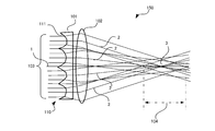
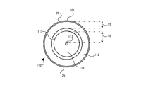
- FIG. 1 is a schematic diagram of a phase filter 101 and an imaging optical system 150 on which the phase filter 101 according to the first embodiment is mounted.
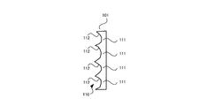
- FIG. 2 is a plan view showing the structure of the phase filter 101 according to the first embodiment.
- the phase filter 101 has a disk-like outer shape and a rotationally symmetric shape with the optical axis 1 as the center. Further, in this phase filter 101, a plurality of rows of grooves having a parabolic cross section, that is, concave surfaces 112, are concentrically centered on the optical axis 1 described above at substantially equal intervals.
- the concave surface 112 formed concentrically around the optical axis 1 in this manner is referred to as an annular zone 111, and the annular zone 111 and the like are collectively referred to as an annular zone structure 110.
- the example of the phase filter 101 shown in FIGS. 1 to 3 has an annular structure 110 composed of two rows of annular zones 111.
- the annular zone 111 is a concave surface that acts as a concave lens in the radial direction of the pupil plane with respect to the light incident on the annular zone 111. Note that the width of the annular zone 111 in the phase filter 101 shown here is equal between the annular zones.
- the imaging lens 102 is arranged so that the phase filter 101 and the optical axis 1 are in common.
- the imaging lens 102 is a lens that can form an image of the object space at a predetermined position on the optical axis 1 when the phase filter 101 is not provided.
- the imaging optical system 150 By forming the imaging optical system 150 with a configuration in which the imaging lens 102 is combined with the phase filter 101, the light beam 103 (incident light beam) incident on the phase filter 101 is refracted by the concave surface 112 described above, and is locally divergent light. It becomes.
- the curvature of the concave surface 112 in the phase filter 101 is set so that the diverging light becomes a locally substantially parallel light beam (on the paper surface) by the imaging lens 102.
- substantially parallel locally refers to a state in which the light rays of the concave surfaces 112 that have passed through the concave surfaces 112 are substantially parallel after passing through the imaging lens 102.
- the propagation direction of the local substantially parallel light beam is directed to the original focal position 3 along the refraction direction of the light beam 2 passing through the center of the annular zone 111.
- a virtual tangential plane with respect to the concave surface 112 (parabolic cross section) at the center of the annular zone 111 is perpendicular to the optical axis 1 of the imaging lens 102, and rays passing therethrough are not refracted by the phase filter 101.
- the substantially parallel light fluxes from the plurality of annular zones 111 overlap in the range 104 in the optical axis direction in the vicinity of the focal point 3.
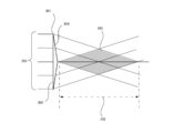
- the light beam diverging and refracted by the imaging lens 102 from each annular zone 111 has been described as a substantially parallel light beam.
- the propagation form is a light beam propagating along the side surface of the cone.
- Such a light beam is a light beam similar to a refracted light beam by the axicon 201 shown in FIG.
- the axicon 201 is a conical lens in which a first surface is a flat bottom surface 202 and a second surface is a cone, and is also called an axicon prism.
- FIG. 4 schematically shows the relationship between the side cross section of the axicon 201, the optical axis 1, and the incident parallel light beam 203.
- the parallel light beam 203 incident from the bottom surface 202 of the axicon 201 is refracted by the inclined side surface 204 of the axicon 201 and is uniformly converged in an optical path along a virtual conical surface.
- a region 205 is formed such that two cones are bonded together with their bottom surfaces facing each other (see FIG. 4 is colored with the intention of clearly indicating the corresponding area).
- a non-diffracted beam is formed in a range 202 in the optical axis direction. 1 corresponds to the fact that a plurality of light beams of the axicon 201 illustrated in FIG. 4 overlap at different angles, and a plurality of non-diffracted beams overlap. Smoothing of the image distribution in the focal direction is achieved.
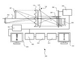
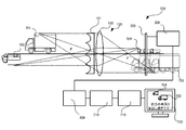
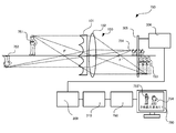
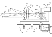
- the configuration of the imaging optical system 150 using the phase filter 101 and the imaging system 300 that performs image processing on an image captured by the imaging optical system 150 will be described with reference to FIG.
- the object 301 exists at a relatively short distance from the imaging optical system 150 and the object 302 exists at a far distance.
- the imaging system 300 has a configuration in which the image sensor 305 is disposed at a position where the images 303 and 304 and the like overlap in the optical axis direction.
- the imaging system 300 converts the output signal from the image sensor 305 described above into an appropriate still image or video image format and outputs it as an image signal while maintaining the highest resolution information that can be output by the image sensor 305.
- An image signal output circuit 306 is provided.
- the imaging system 300 includes a monitor output generation circuit 307 that receives the image signal output from the image signal output circuit 306, converts the image signal into a format that can be displayed on the display, and outputs the image signal on the monitor display 308. As schematically shown in FIG. 5, images 303 and 304 in which the near object 301 and the distant object 302 are uniformly blurred are obtained as images displayed on the monitor display 308. However, since such monitor output processing is not essential for the imaging system 300, there is no problem even if the monitor display 308 and the monitor output generation circuit 307 are not included.
- the imaging system 300 also includes a deconvolution preprocessing circuit 309 and a deconvolution filter circuit 310.
- the output signal from the image signal output circuit 306 described above is branched and input to the deconvolution preprocessing circuit 309.
- the deconvolution preprocessing circuit 309 converts the digital image data format suitable for the filter operation in the deconvolution filter circuit 310.
- the output signal of the deconvolution preprocessing circuit 309 is filtered by the deconvolution filter circuit 310 and input to the second monitor output generation circuit 311.
- the second monitor output generation circuit 311 converts the input signal from the deconvolution filter circuit 310 into an arbitrary general still image or moving image format, and outputs and displays it as an output signal on the second monitor display 312.
- FIG. 6 is a schematic diagram for formulating the shape of the parabolic cross section (that is, the concave surface 112) in the phase filter 101.
- the horizontal axis indicates the radius coordinate of the pupil plane
- the vertical axis indicates the shape of the phase filter 101. Further, only one period is displayed here, and even is shown when the optical axis position with a radius of 0 has a sharp apex, and odd when the bottom of the parabola is on the optical axis.
- the depth of the parabolic section is d. This shape is repeated in the radial direction with a period p.
- Such a shape is If we expand the Fourier series like It can be expressed as Where the period p is It is.
- r n is the radius of the n-th annular zone 111, which corresponds to a pupil radius of the imaging optical system 150.
- Such an annular structure 110 is an annular structure in which the width and the phase difference of the annular zone 111 are all equal. It is assumed that the phase filter 101 is disposed on the pupil plane of the imaging optical system 150. In the actual imaging optical system 150, this may be arranged at the stop position.
- the sectional shape of the annular zone 111 is assumed to be a parabolic sectional shape, but this is not necessarily limited to the sectional shape being described by a quadratic function with respect to local radial coordinates. Not what you want.
- a circular or elliptical cross section may be used.
- the quadratic expansion term with respect to the radius is dominant in the vicinity of the apex of the cross section of the annular zone 111, so that it is described as a parabolic cross section.
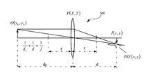
- FIG. 7 there is an object given by a light intensity distribution O (x0, y0) at a distance d 0 by an imaging optical system 500 having a focal length f, and the optical image intensity distribution I (x, y) is Assume that an image is formed at a position of distance d based on the imaging formula in the figure.
- the image I (x, y) is formed by superposition of the wave optical point image distribution PSF (x, y) of the point light sources. is there.
- the spatial frequency spectrum of the image plane light intensity distribution is the product of the spatial frequency spectrum of the object plane and the spatial frequency spectrum of the point image distribution.
- the spatial frequency spectrum of the point spread is called the optical transfer function OTF, It is expressed by the autocorrelation calculation of the pupil function.
- OTF optical transfer function
- the image plane intensity distribution is On the contrary, if the image plane intensity distribution and OTF are known, the geometrical mapping of the light intensity distribution on the object plane on the image plane, that is, the ideal optical image, It can be expressed as This operation is called deconvolution. Deconvolution requires that the OTF does not become zero, as can be seen from the form of the equation. Even when images with different object distances are mixed in the image plane, an ideal optical image can be uniformly obtained by deconvolution if the point image distribution is the same regardless of the defocus.
- FIG. 8 shows a comparative example of the processing result of the captured image depending on the presence or absence of the phase filter 101 of the first embodiment.
- the simulation conditions in the simulation result 510 shown in FIG. 8 are: focal length 50 mm, effective diameter 15.625 mm, F number 3.2, wavelength 0.5 ⁇ m, object distance 710 mm, sensor size 15 mm, annular zone pitch 0.8 mm, The phase difference is 4.24 ⁇ , the odd case, the approximate order is 8th, and the image size is 1024 ⁇ 1024.
- the OTF used for deconvolution uses the average of OTF with 0 mm defocus and 1 mm OTF.
- the gradation of an image acquired by a camera that is, an imaging optical system or an imaging system
- the original image is a spoke-like monochrome image with 0 and maximum brightness
- the upper stage is a normal acquired image without the phase filter 101
- the middle stage is a camera acquired image when the phase filter 101 of the first embodiment is applied
- the lower stage is a deconvolution. It is a result image.
- the column direction is ⁇ 2, ⁇ 1, 0, 1, 2 mm from the left in terms of the defocus amount of the sensor surface. In this case, minus means that the sensor is close to the lens, and plus means that the sensor is far from the lens.
- the calculation result of the evaluation index value of the image is shown by a white number on the lower left of the image after the deconvolution processing without the phase filter 101.
- the image evaluation index is a numerical value called PSNR (Peak Signal to Noise Ratio), Defined by Here, Max is maximum luminance, m and n are horizontal and vertical image sizes, I (i, j) is an evaluation image, and O (i, j) is an original image. From this result, it can be seen that although it does not reach a normal image without defocus, there is no noticeable image degradation within a defocus range of ⁇ 2 mm, and the depth of focus is increased.
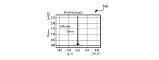
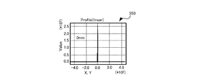
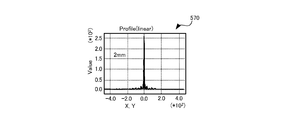
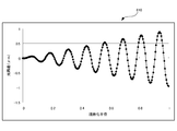
- FIG. 9 shows the wavefront aberration of the pupil plane, that is, the phase distribution 520 by the phase filter 101 of the first embodiment. However, here, the defocus wavefront aberration is not included. It can be seen that each annular zone 111 has a parabolic cross-sectional phase shift.
- the horizontal axis represents the pixel position of the image
- the vertical axis represents the luminance
- the calculation area range is 0.938 mm.
- the graph shows the calculation results when the defocus amount is set to -2, -1, 0, 1, 2 mm from the upper left to the lower right.
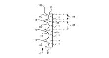
- FIG. 15 is a plan view showing the structure of the phase filter 101 of the second embodiment
- FIG. 16 is a side sectional view showing the structure of the phase filter 101 of the second embodiment.
- the phase filter 101 has an annular ring 111 including a concave surface 112 that acts as a concave lens in the radial direction of the pupil plane with respect to an incident light beam, and an annular zone 114 that includes a convex surface 113 that acts as a convex lens. It has a band structure 110.
- FIG. 17 shows the wavefront aberration of the pupil plane, that is, the phase distribution 580, by the phase filter 101 having such a structure.
- the horizontal axis represents the normalized radius of the pupil plane
- the vertical axis represents the optical path difference ( ⁇ m).
- ⁇ m the optical path difference
- the refractive action of the annular zone 111 does not act on the light flux incident between the annular zones 111 (the annular zone acting as a concave lens) in the phase filter 101 of the first embodiment, that is, the steep and sharp convex portion.
- the incident light is incident on a region near the annular zone 114 on the concave surface 112 of the annular zone 111.
- the light beam to be reflected can be refracted as desired by the convex lens action of the annular zone 114, and its phase distribution 580 does not show a sharp peak as in the phase distribution 520 (FIG. 9) of the first embodiment, and is smooth. Shape.
- the phase filter 101 having such a structure, the steep and sharp convex portions as described above do not exist between the annular zones, so that occurrence of chipping in the phase filter 101 can be suppressed.
- the concave lens zone 111 and the convex lens zone 114 have been described for the sake of convenience. However, in practice, the zone width is defined with a region where both are integrated as one zone.
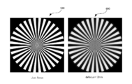
- FIG. 18 shows an image after deconvolution when the phase filter 101 in the second embodiment is used.
- conditions other than the phase filter are the same as those in the first embodiment.
- the left image 590 is a case where there is no defocus (Just focus), and the right image 600 is a case where the defocus is 2 mm.
- the image quality is slightly inferior to that of the first embodiment, it can be seen that there is an effect of expanding the depth of focus similar to that of the first embodiment.
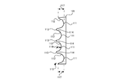
- the depth of the concave surface 112 is the same in the vicinity of the optical axis 1 and in the peripheral portion 25, The closer to 1, the greater the change in the point where the light beam intersects the optical axis 1.
- This can be considered to be equivalent to the fact that the contribution to the expansion of the depth of focus is larger as it is closer to the optical axis 1 and is smaller as the peripheral portion 25 is smaller. Therefore, an example of the phase filter 101 in which the depth of the concave surface 112 becomes deeper as the peripheral edge 25 is described below. Note that the depth of the concave surface 112 in the annular zone 111 increases from the optical axis 1 toward the peripheral edge 25, but the annular zone width is constant in all annular zones.
- FIG. 19 is a plan view showing the structure of the phase filter of the third embodiment
- FIG. 20 is a side sectional view showing the structure of the phase filter of the third embodiment.
- the depth 117 of the concave surface 112 in the outermost annular zone 111 closest to the peripheral portion 25 is deeper than the depth 118 of the concave surface 112 in the inner peripheral annular zone 111.
- the phase filter 101 has an annular ring 111 including a concave surface 112 that acts as a concave lens in the radial direction of the pupil plane with respect to an incident light beam, and an annular zone 114 that includes a convex surface 113 that acts as a convex lens. It has a band structure 110.
- FIG. 21 shows the wavefront aberration of the pupil plane by the phase filter 101 having such a structure, that is, the phase distribution 610.
- the change in the optical path difference increases as the depth of the concave surface 112 of the annular zone 111 in the phase filter 101 increases, and the amount of change in the phase shift also increases.
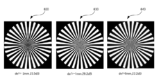
- FIG. 22 shows an image after deconvolution when the phase filter 101 in the third embodiment is used.
- conditions other than the phase filter are the same as those in the first embodiment.
- the image 620 on the left side of the page is a case where the focus shift is ⁇ 2 mm
- the center image 630 is a focus shift ⁇ 1 mm
- the right image 640 is a case where the focus shift is 0 mm.
- the dB value shown below each image is PSNR (Peak Signal-to-Noise Ratio). It can be seen that almost the same image quality as in the first embodiment is obtained.
- PSNR Peak Signal-to-Noise Ratio
- the phase filter 101 is a technique for expanding the effective depth of focus of the imaging optical system 150, and various application uses are conceivable.
- An example of an apparatus using the phase filter 101 will be described below in accordance with the application application.
- FIG. 23 is a diagram illustrating a configuration example of the vehicle travel support apparatus 700 according to the second embodiment
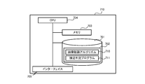
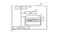
- FIG. 24 is a diagram illustrating a hardware configuration example of the information processing apparatus 710 included in the vehicle travel support apparatus 700 according to the second embodiment. is there.
- an apparatus that incorporates the phase filter 101 into an in-vehicle camera to photograph an obstacle around the vehicle and detects an obstacle to prevent a collision based on an image captured by the in-vehicle camera, that is, a vehicle travel support apparatus 700 can be assumed. .
- the vehicle travel support device 700 includes an image sensor 305, an image signal output circuit 306, a deconvolution preprocessing circuit 309, and a deconvolution filter circuit 310.
- the information processing device 710 is included. Further, the processing result in the information processing device 710 is displayed on the monitor display of the car navigation device 730 provided in the vehicle.
- the reflected light of other vehicles 701 and 702 existing around the vehicle on which the vehicle driving support device 700 is mounted enters the imaging lens 102 via the phase filter 101 in the imaging optical system 150.
- images 703 and 704 with uniform blurring in the direction of the optical axis 1 are formed. Therefore, in the vehicle travel support device 700, the image sensor 305 obtains sensing data of the images 703 and 704 and provides them to the image signal output circuit 306.
- the deconvolution preprocessing circuit 309 receives the image signal output from the image signal output circuit 306 and converts it into a digital image data format suitable for the filter operation in the deconvolution filter circuit 310.
- the output signal of the deconvolution preprocessing circuit 309 is filtered by the deconvolution filter circuit 310 and is input to the information processing device 710.
- the car navigation device 730 displays an image focused on the vehicle 702 and outputs sound such as a warning notification in response thereto.
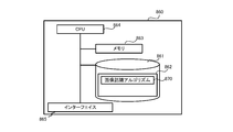
- the hardware configuration of the information processing apparatus 710 included in the vehicle travel support apparatus 700 is as follows.
- the information processing device 710 reads into the memory 703 a storage device 701 configured with an appropriate non-volatile storage device such as a hard disk drive, a memory 703 configured with a volatile storage device such as a RAM, and a program 702 held in the storage device 701.
- a central processing unit (CPU) 704 for performing overall control of the apparatus itself and performing various determinations, computations and control processing, and 705 (display, keyboard, mouse, etc.) for receiving user input and outputting results.
- the program 702 at least an image recognition algorithm 710 for implementing functions necessary for the vehicle travel support apparatus 700 and an approach determination program 711 are stored. The processing of the program 702 will be described later.
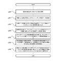
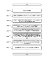
- the imaging optical system 150 captures the other vehicles 701 and 702, which are objects around the vehicle (s100), and the image sensor 305 senses the images 703 and 704 obtained by the imaging to acquire image data. (S101).
- the image sensor 305 provides the above-described image data to the image signal output circuit 306 as an image signal, and the image signal output circuit 306 maintains an appropriate still image or information while maintaining the highest resolution information that can be output by the image sensor 305.
- the image is converted into a moving image format and output to the deconvolution preprocessing circuit 309 as an image signal (s102).
- the deconvolution preprocessing circuit 309 receives the image signal output from the image signal output circuit 306 and converts it into a digital image data format suitable for the filter operation in the deconvolution filter circuit 310 (s103).
- the output signal of the deconvolution preprocessing circuit 309 is filtered by the deconvolution filter circuit 310 and input to the information processing apparatus 710 (s104).
- the information processing device 710 acquires the output data of the deconvolution filter circuit 310, that is, the depth-of-focus enlarged image, and applies the image recognition algorithm 710 for vehicle recognition to the depth-of-focus enlarged image, from the own vehicle.
- a plurality of objects such as other vehicles 701 and 702 that exist at different distances and are within a certain distance from the host vehicle are simultaneously detected (s105).
- the image recognition algorithm 710 for example, performs image processing such as specifying and highlighting a shape or size region (corresponding to the vehicle shape) of a predetermined color set of pixels for pixels constituting the original image. The algorithm to perform.
- the information processing device 710 causes the car navigation device 730 to display the images 703 and 704 of the other vehicles 701 and 702 detected in step s105, and displays a notification message warning that the other vehicles 701 and 702 are approaching.
- the car navigation device 730 displays or outputs the sound (s106). According to such a vehicle travel support device 700, it is possible to simultaneously detect an obstacle at a position close to the host vehicle and an obstacle at a position far away from the host vehicle, thereby improving safety during vehicle travel.
- FIG. 26 is a diagram illustrating a configuration example of the monitoring device 750 according to the third embodiment
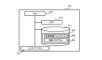
- FIG. 27 is a diagram illustrating a hardware configuration example of the information processing device 760 included in the monitoring device 750 according to the third embodiment.
- the monitoring device 750 includes an image sensor 305, an image signal output circuit 306, a deconvolution preprocessing circuit 309, and a deconvolution filter circuit 310.
- a processing unit 760 is included. Further, the processing result in the information processing device 760 is displayed on the monitor display 780.
- the reflected light of the persons 751 and 752 existing in the monitoring target region spreading around the monitoring device 750 is incident on the imaging lens 102 via the phase filter 101 in the imaging optical system 150, and the direction of the optical axis 1. Images 753 and 754 with uniform blurring are formed. Therefore, in the monitoring device 750, the image sensor 305 obtains sensing data of the images 753 and 754 and provides this to the image signal output circuit 306.
- the deconvolution preprocessing circuit 309 receives the image signal output from the image signal output circuit 306 and converts it into a digital image data format suitable for the filter operation in the deconvolution filter circuit 310.
- the output signal of the deconvolution preprocessing circuit 309 is filtered by the deconvolution filter circuit 310 and input to the information processing device 760, and after a predetermined process, the person 752 far from the close person 751 described above.
- the monitor display 780 displays a focused image and outputs a warning notification or the like accordingly.
- the hardware configuration of the information processing device 760 included in such a monitoring device 750 is as follows.
- the monitoring device 750 includes a storage device 761 configured by an appropriate non-volatile storage device such as a hard disk drive, a memory 763 configured by a volatile storage device such as a RAM, and reads a program 762 held in the storage device 761 to the memory 763.
- a CPU 764 that performs overall control of the apparatus itself and performs various determinations, calculations, and control processes, and 765 (display, keyboard, mouse, etc.) that accepts user input and outputs results.
- the program 762 stores at least an image recognition algorithm 770 for implementing functions necessary for the monitoring device 750. The processing of the program 702 will be described later.
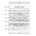
- the imaging optical system 150 images the persons 751 and 752 located in the monitoring target area (s200), and the image sensor 305 senses images 753 and 754 obtained by the imaging to acquire image data (s201). ).
- the image sensor 305 provides the above-described image data to the image signal output circuit 306 as an image signal, and the image signal output circuit 306 maintains an appropriate still image or information while maintaining the highest resolution information that can be output by the image sensor 305.
- the image is converted into a moving image format and output to the deconvolution preprocessing circuit 309 as an image signal (s202).
- the deconvolution preprocessing circuit 309 receives the image signal output from the image signal output circuit 306 and converts it into a digital image data format suitable for the filter operation in the deconvolution filter circuit 310 (s203).
- the output signal of the deconvolution preprocessing circuit 309 is filtered by the deconvolution filter circuit 310 and input to the information processing apparatus 760 (s204).
- the information processing device 760 acquires the output data of the deconvolution filter circuit 310, that is, the depth of focus enlarged image, applies the image recognition algorithm 770 for person recognition to the depth of focus enlarged image, and monitors the monitoring device 750. And a plurality of persons 751 and 752 within a certain distance from the monitoring device 750, that is, in the monitoring target area, are simultaneously detected (s205).
- the image recognition algorithm 770 specifies, for example, a pixel set shape and size region (corresponding to a person's outer shape) of a predetermined color for pixels constituting the original image, and highlights the image processing. It becomes an algorithm to do.
- the information processing apparatus 760 displays the images 753 and 754 of the persons 751 and 752 detected in step s205 on the monitor display 780, and notifies the user that these persons 751 and 752 have entered the monitoring target area. Is displayed on the monitor display 780 or output as a sound (s206). According to such a monitoring apparatus 750, the recognition rate of a suspicious person or a criminal who has entered or is in the monitoring target area is improved regardless of the location distance from the imaging optical system.
- FIG. 29 is a diagram illustrating a configuration example of an authentication device according to the fourth embodiment
- FIG. 30 is a diagram illustrating a hardware configuration example of an information processing device included in the authentication device according to the fourth embodiment.
- the authentication apparatus 800 includes an image sensor 305, an image signal output circuit 306, a deconvolution preprocessing circuit 309, and a deconvolution filter circuit 310.
- a processing device 810 is included.
- the processing result in the information processing apparatus 810 is displayed on the monitor display 830.
- the reflected light of the fingers 801 and 802 that are to be authenticated by the authentication apparatus 800 (eg, fingers, palms, wrists, pupils serving as iris authentication parts, etc.)
- the light enters the imaging lens 102 via the phase filter 101 in the optical system 150, and forms images 803 and 804 with uniform blurring in the direction of the optical axis 1. Therefore, in the authentication apparatus 800, the image sensor 305 obtains sensing data of the images 803 and 804 and provides this to the image signal output circuit 306.
- the deconvolution preprocessing circuit 309 receives the image signal output from the image signal output circuit 306 and converts it into a digital image data format suitable for the filter operation in the deconvolution filter circuit 310.
- the output signal of the deconvolution preprocessing circuit 309 is filtered by the deconvolution filter circuit 310 and input to the information processing device 810. After a predetermined process, the shooting distance from the imaging optical system 150 is short.
- the monitor display 830 displays an image focused on the finger 801 at the occasion where the image is taken or the finger 802 at the time when the shooting distance is long, and displays the authentication processing result or outputs the sound accordingly. .
- the hardware configuration of the information processing apparatus 810 included in the authentication apparatus 800 is as follows.
- the information processing device 810 reads, to the memory 813, a storage device 811 configured with an appropriate nonvolatile storage device such as a hard disk drive, a memory 813 configured with a volatile storage device such as a RAM, and a program 812 held in the storage device 811.
- a CPU 814 for performing overall control of the apparatus itself and performing various determinations, computations and control processes, and 815 (display, keyboard, mouse, etc.) for receiving user input and outputting results.
- the program 812 stores at least an image recognition algorithm 880 for implementing a function necessary for the authentication apparatus 800 and an authentication program 881. The processing of the program 812 will be described later.
- the imaging optical system 150 in the authentication apparatus 800 images the authentication objects 801 and 802 (s300), and the image sensor 305 senses images 803 and 804 obtained by the imaging to acquire image data (s301).
- the image sensor 305 provides the above-described image data to the image signal output circuit 306 as an image signal, and the image signal output circuit 306 maintains an appropriate still image or information while maintaining the highest resolution information that can be output by the image sensor 305. It is converted into a moving image format and output to the deconvolution preprocessing circuit 309 as an image signal (s302).
- the deconvolution preprocessing circuit 309 receives the image signal output from the image signal output circuit 306 and converts it into a digital image data format suitable for the filter operation in the deconvolution filter circuit 310 (s303).
- the output signal of the deconvolution preprocessing circuit 309 is filtered by the deconvolution filter circuit 310 and input to the information processing apparatus 810 (s304).
- the information processing apparatus 810 acquires the output data of the deconvolution filter circuit 310, that is, the depth-of-focus enlarged image, and applies the image recognition algorithm 770 for recognition object recognition to the depth-of-focus enlarged image to obtain an authentication opportunity.
- the authentication data is image data corresponding to images 803 and 804 such as fingerprints, veins, and irises.
- the image recognition algorithm 770 identifies and highlights a pixel set shape and size region (corresponding to the shape of a fingerprint, vein, iris, etc.) of a predetermined color for pixels constituting the original image. This is an algorithm for performing image processing such as.
- the information processing device 810 inputs the image data of the authentication targets 801 and 802 obtained in step s305 to the authentication program 881, extracts the feature data by the authentication program 881, and extracts the feature data and a predetermined template (authentication target).
- a general authentication process is performed by executing each process of matching with authentication standard data prepared in advance for each person (s306).
- the information processing apparatus 810 displays or outputs the authentication result obtained in step s306 on the monitor display 830 (s307). According to such an authentication apparatus 800, even if there is a situation where the distance of the authentication target (human fingerprint, vein, iris, etc.) to the imaging optical system 150 changes every time authentication is performed, such a variation in distance is appropriately absorbed. As a result, the accuracy of authentication can be improved.
- the distance of the authentication target human fingerprint, vein, iris, etc.
- FIG. 32 is a diagram illustrating a configuration example of the medical device 850 according to the fifth embodiment
- FIG. 33 is a diagram illustrating a hardware configuration example of the information processing device 860 included in the medical device 850 according to the fifth embodiment.
- the medical device 850 includes an image sensor 305, an image signal output circuit 306, a deconvolution preprocessing circuit 309, and a deconvolution filter circuit 310.
- a processing unit 860 is included. Further, the processing result in the information processing device 860 is displayed on the monitor display 880.
- the reflected light of the affected areas 851 and 852 that become medical treatment target areas (eg, medical treatment, organs for medical examination) in the medical device 850 passes through the phase filter 101 in the imaging optical system 150 to the imaging lens 102.
- Incident light forms images 853 and 854 with uniform blurring in the direction of the optical axis 1. Therefore, in the medical device 850, the image sensor 305 obtains sensing data of the images 853 and 854 and provides this to the image signal output circuit 306.
- the deconvolution preprocessing circuit 309 receives the image signal output from the image signal output circuit 306 and converts it into a digital image data format suitable for the filter operation in the deconvolution filter circuit 310.
- the output signal of the deconvolution preprocessing circuit 309 is filtered by the deconvolution filter circuit 310 and input to the information processing device 860, and after a predetermined process, the affected part 851 that is close to the imaging optical system 150.
- the monitor display 880 displays an image focused on the affected area 852 which is far away.
- the hardware configuration of the information processing device 860 included in the medical device 850 is as follows.
- the information processing device 860 reads, to the memory 863, a storage device 861 configured with an appropriate nonvolatile storage device such as a hard disk drive, a memory 863 configured with a volatile storage device such as a RAM, and a program 862 held in the storage device 861.
- a CPU 864 that performs overall control of the apparatus itself and performs various determinations, calculations, and control processing, and 865 (display, keyboard, mouse, etc.) that accepts user input and outputs results.
- the program 862 stores at least an image recognition algorithm 870 for implementing functions necessary for the medical device 850. The processing of the program 862 will be described later.
- the imaging optical system 150 in the medical device 850 images the affected areas 851 and 852 in the medical treatment target area (s400), and the image sensor 305 senses images 853 and 854 obtained by the imaging to acquire image data (s401). .
- the image sensor 305 provides the above-described image data to the image signal output circuit 306 as an image signal, and the image signal output circuit 306 maintains an appropriate still image or information while maintaining the highest resolution information that can be output by the image sensor 305.
- the image is converted into a moving image format and output to the deconvolution preprocessing circuit 309 as an image signal (s402).
- the deconvolution preprocessing circuit 309 receives the image signal output from the image signal output circuit 306 and converts it into a digital image data format suitable for the filter operation in the deconvolution filter circuit 310 (s403).
- the output signal of the deconvolution preprocessing circuit 309 is filtered by the deconvolution filter circuit 310 and input to the information processing device 860 (s404).
- the information processing apparatus 860 acquires the output data of the deconvolution filter circuit 310, that is, the depth-of-focus enlarged image, and applies the image recognition algorithm 870 of the affected area to the depth-of-focus enlarged image to capture an image in the medical treatment target region.
- Image data of a plurality of affected areas 851 and 852 existing at different distances from the optical system 150 is obtained (s405).
- the image recognition algorithm 870 specifies, for example, a pixel set shape and size region (corresponding to the shape of the affected part) of a predetermined color for pixels constituting the original image, and performs image processing such as highlighting. It becomes an algorithm to do.
- the information processing apparatus 860 displays the image data of the affected parts 851 and 852 obtained in step s405 on the monitor display 880 (s406). According to such a medical device 850, the simultaneous visibility of the affected part in the medical staff is enhanced regardless of the distance of the affected part from the imaging optical system 150. This facilitates the design of an optical system in a medical camera and the like, and the number of required lenses can be reduced, leading to a reduction in manufacturing cost.
- the in-plane positional shift of the image point corresponding to the defocus is eliminated, and the phase filter of the present embodiment and the optical system using the phase filter And the imaging system can be used for the purpose of measuring the object position by the position of the point image.
- the optical aspheric surface serving as the phase filter has a rotationally symmetric shape
- the mold used for forming the optical aspherical surface also has a rotationally symmetric shape, so that a rotating lathe can be processed when the mold is manufactured. Therefore, it is possible to shorten the production time of the phase filter mold and to reduce the manufacturing cost.
- an annular structure in the phase filter by introducing an annular structure in the phase filter, a large uneven shape is unnecessary, that is, the unevenness of the element is reduced, and the shift of the phase shift amount with respect to the light having a field angle can be reduced.
- an optical system equivalent to configuring the axicon in a ring shape can be realized, and application to the imaging optical system is possible.
- the annular zone may have a concave surface that acts as a concave lens in the radial direction of the pupil plane with respect to the incident light flux.
- the optical aspheric surface serving as the phase filter has a rotationally symmetric shape in which the annular concave surfaces are arranged concentrically, and the mold used for the molding also has a rotationally symmetric shape. Is possible. Therefore, it is possible to shorten the production time of the phase filter mold and to reduce the manufacturing cost. Further, by introducing such an annular structure in the phase filter, a large uneven shape is not required, that is, the unevenness of the element is reduced, and the shift of the phase shift amount with respect to the light having a field angle can be reduced.
- the annular zone may alternately include a concave surface that acts as a concave lens and a convex surface that acts as a convex lens in the radial direction of the pupil plane with respect to the incident light flux.
- the wavefront aberration of the pupil plane due to the phase distribution that is, the sharp peak in the phase distribution is eliminated, and the phase distribution is smooth compared with the case where the annular structure is formed only by the annular zone acting as a concave lens. Therefore, occurrence of chipping can be suppressed by the manufactured phase filter.
- the width of the annular zone may be equal between the annular zones. According to this, since the zonal structure in the phase filter becomes simple, it is possible to shorten the manufacturing time and the manufacturing cost of the mold used for the molding.
- the phase difference applied by the annular zones may be equal between the annular zones. According to this, the same phase shift can be added between each annular zone in the phase filter.
- each annular zone may be narrowed from the optical axis toward the peripheral edge of the phase filter. According to this, the area contributed by each annular zone can be made uniform, and the influence of manufacturing variations can be reduced.
- the phase difference applied by the annular zone may be larger in the peripheral portion of the phase filter than in the vicinity of the optical axis. According to this, the contribution of the phase filter to the expansion of the depth of focus in each annular zone can be leveled regardless of the distance from the optical axis.
- 1, 5, 23, 26, 29, and 32 each have a structure in which a phase plate having a single-sided flat surface or a single-sided phase structure is inserted. Even if the phase structure is directly formed on the lens surface close to, the effect is the same, so the phase filter may be directly formed integrally on such a lens surface.
- a lens optical system to which the present invention is applied not only a lens having a fixed focal length but also a zoom lens optical system having a variable focal length can be applied. If a phase filter is disposed in the vicinity of the stop or the pupil plane, there is some change in the depth of focus expansion effect, but it is basically applicable. Along with an increase in the depth of field that can be photographed, the focus adjustment between the image and the sensor surface becomes easy, and the focus adjustment mechanism can be eliminated.
Landscapes
- Physics & Mathematics (AREA)
- Engineering & Computer Science (AREA)
- General Physics & Mathematics (AREA)
- Optics & Photonics (AREA)
- Multimedia (AREA)
- Signal Processing (AREA)
- Theoretical Computer Science (AREA)
- Computer Vision & Pattern Recognition (AREA)
- Computing Systems (AREA)
- Studio Devices (AREA)
- Lenses (AREA)
- Optical Elements Other Than Lenses (AREA)
- Blocking Light For Cameras (AREA)
- Image Processing (AREA)
Priority Applications (4)
| Application Number | Priority Date | Filing Date | Title |
|---|---|---|---|
| CN201380075190.7A CN105122092B (zh) | 2013-03-29 | 2013-10-16 | 相位滤波器、光学成像系统以及成像系统 |
| US14/780,972 US9967441B2 (en) | 2013-03-29 | 2013-10-16 | Phase filter, imaging optical system, and imaging system |
| US15/962,907 US10477086B2 (en) | 2013-03-29 | 2018-04-25 | Phase filter, imaging optical system, and imaging system |
| US16/590,733 US11209643B2 (en) | 2013-03-29 | 2019-10-02 | Phase filter, imaging optical system, and imaging system |
Applications Claiming Priority (2)
| Application Number | Priority Date | Filing Date | Title |
|---|---|---|---|
| JP2013072388A JP6396638B2 (ja) | 2013-03-29 | 2013-03-29 | 位相フィルタ、撮像光学系、及び撮像システム |
| JP2013-072388 | 2013-03-29 |
Related Child Applications (2)
| Application Number | Title | Priority Date | Filing Date |
|---|---|---|---|
| US14/780,972 A-371-Of-International US9967441B2 (en) | 2013-03-29 | 2013-10-16 | Phase filter, imaging optical system, and imaging system |
| US15/962,907 Continuation US10477086B2 (en) | 2013-03-29 | 2018-04-25 | Phase filter, imaging optical system, and imaging system |
Publications (1)
| Publication Number | Publication Date |
|---|---|
| WO2014155790A1 true WO2014155790A1 (ja) | 2014-10-02 |
Family
ID=51622828
Family Applications (1)
| Application Number | Title | Priority Date | Filing Date |
|---|---|---|---|
| PCT/JP2013/078090 Ceased WO2014155790A1 (ja) | 2013-03-29 | 2013-10-16 | 位相フィルタ、撮像光学系、及び撮像システム |
Country Status (4)
| Country | Link |
|---|---|
| US (3) | US9967441B2 (enExample) |
| JP (1) | JP6396638B2 (enExample) |
| CN (2) | CN109188684B (enExample) |
| WO (1) | WO2014155790A1 (enExample) |
Cited By (3)
| Publication number | Priority date | Publication date | Assignee | Title |
|---|---|---|---|---|
| JP2018101065A (ja) * | 2016-12-21 | 2018-06-28 | 株式会社日立製作所 | 光学部品およびそれを用いた撮像システム |
| CN109143608A (zh) * | 2018-10-11 | 2019-01-04 | 中国人民解放军国防科技大学 | 基于菲涅尔透镜和固态变焦透镜的波长选择装置及方法 |
| JP2022071235A (ja) * | 2020-10-28 | 2022-05-16 | 株式会社日立製作所 | 撮像光学系、撮像装置および焦点深度拡大光学システム |
Families Citing this family (12)
| Publication number | Priority date | Publication date | Assignee | Title |
|---|---|---|---|---|
| JP6471031B2 (ja) * | 2015-04-15 | 2019-02-13 | マクセル株式会社 | 位相フィルタ、撮像光学系、及び撮像システム |
| WO2016194218A1 (ja) * | 2015-06-05 | 2016-12-08 | 日立マクセル株式会社 | 撮像補助装置、およびそれを用いた撮像装置 |
| JP6470654B2 (ja) | 2015-07-24 | 2019-02-13 | 株式会社日立ハイテクノロジーズ | 荷電粒子線装置 |
| CN107710741B (zh) * | 2016-04-21 | 2020-02-21 | 华为技术有限公司 | 一种获取深度信息的方法及摄像装置 |
| JP6905838B2 (ja) * | 2017-03-03 | 2021-07-21 | 株式会社日立ハイテク | 生体分子分析装置および生体分子分析方法 |
| CN108132529A (zh) * | 2017-03-03 | 2018-06-08 | 中国北方车辆研究所 | 一种基于波前编码的景深变焦光学方法及系统 |
| JP2020181629A (ja) | 2017-07-27 | 2020-11-05 | 株式会社日立ハイテク | 電子線観察装置、電子線観察システム及び電子線観察装置の制御方法 |
| CN108563034B (zh) * | 2018-01-26 | 2020-08-04 | 中国科学院上海光学精密机械研究所 | 反射型空间滤波器调试装置和方法 |
| CN108171858A (zh) * | 2018-02-13 | 2018-06-15 | 南京东屋电气有限公司 | 一种带有分离式红外图像采集装置的汽车门锁 |
| US10615067B2 (en) * | 2018-05-18 | 2020-04-07 | Kla-Tencor Corporation | Phase filter for enhanced defect detection in multilayer structure |
| BE1027429B1 (nl) * | 2019-11-07 | 2021-02-08 | Innovate Prec Besloten Vennootschap Met Beperkte Aansprakelijkheid | Werkwijze en apparaat voor het verkrijgen van een beeld met uitgebreide scherptediepte |
| JP2020204786A (ja) * | 2020-09-17 | 2020-12-24 | マクセル株式会社 | 位相フィルタ、撮像光学系、及び撮像システム |
Citations (6)
| Publication number | Priority date | Publication date | Assignee | Title |
|---|---|---|---|---|
| JPH03107799U (enExample) * | 1990-02-19 | 1991-11-06 | ||
| JPH07198909A (ja) * | 1993-01-06 | 1995-08-01 | Holo Or Ltd | 多焦点回折レンズ |
| JP2002244050A (ja) * | 2001-02-21 | 2002-08-28 | Asahi Optical Co Ltd | 内視鏡照明光学系 |
| JP2005331784A (ja) * | 2004-05-20 | 2005-12-02 | Fuji Xerox Co Ltd | 光学レンズ系およびこれを用いた位置計測システム |
| JP2007327966A (ja) * | 2007-07-24 | 2007-12-20 | Fuji Xerox Co Ltd | 光源モジュールおよびこれを用いた位置計測システム |
| JP2011128238A (ja) * | 2009-12-16 | 2011-06-30 | Fujitsu Ltd | 撮像装置および情報端末装置 |
Family Cites Families (40)
| Publication number | Priority date | Publication date | Assignee | Title |
|---|---|---|---|---|
| US3669527A (en) * | 1970-12-03 | 1972-06-13 | Scripto Inc | Wide angle photographic objective having nonspherical surfaces |
| US4545653A (en) * | 1981-01-07 | 1985-10-08 | Digital Recording Corporation | Focusing elements and system for producing a prescribed energy distribution along an axial focal zone |
| US5260727A (en) * | 1990-10-22 | 1993-11-09 | Oksman Henry C | Wide depth of focus intraocular and contact lenses |
| US5814803A (en) * | 1994-12-23 | 1998-09-29 | Spectra-Physics Scanning Systems, Inc. | Image reader with multi-focus lens |
| JP3767927B2 (ja) | 1995-01-31 | 2006-04-19 | 沖電気工業株式会社 | 波長変換方法及びそれを用いた波長変換装置 |
| JP3275010B2 (ja) | 1995-02-03 | 2002-04-15 | ザ・リジェンツ・オブ・ザ・ユニバーシティ・オブ・コロラド | 拡大された被写界深度を有する光学システム |
| EP1396737A3 (en) * | 1997-03-11 | 2004-12-29 | Nihon Kohden Corporation | Particle analyzer and composite lens formed by integrally joining plural lens elements of different focal points |
| JP3663920B2 (ja) * | 1998-06-30 | 2005-06-22 | 株式会社ニコン | 位相差観察装置 |
| US6480344B1 (en) * | 1999-11-22 | 2002-11-12 | Asahi Kogaku Kogyo Kabushiki Kaisha | Objective lens for optical pick-up |
| JP3554703B2 (ja) * | 2000-10-12 | 2004-08-18 | リバーベル株式会社 | 情報端末装置 |
| GB0118306D0 (en) * | 2001-07-27 | 2001-09-19 | Isis Innovation | Method of,and apparatus for,generating a focussed light beam |
| JP4249627B2 (ja) * | 2001-12-18 | 2009-04-02 | ザ ユニバーシティ オブ ロチェスター | 多重焦点非球面レンズを使用して拡大焦点距離を得る撮像 |
| US7180673B2 (en) * | 2003-03-28 | 2007-02-20 | Cdm Optics, Inc. | Mechanically-adjustable optical phase filters for modifying depth of field, aberration-tolerance, anti-aliasing in optical systems |
| US6923539B2 (en) * | 2003-05-12 | 2005-08-02 | Alcon, Inc. | Aspheric lenses |
| EP1687829B1 (en) * | 2003-05-30 | 2012-08-08 | CDM Optics, Inc. | Lithographic systems and methods with extended depth of focus |
| US7365917B2 (en) * | 2004-08-16 | 2008-04-29 | Xceed Imaging Ltd. | Optical method and system for extended depth of focus |
| US20060082882A1 (en) * | 2004-10-14 | 2006-04-20 | Wang Michael R | Achromatic imaging lens with extended depth of focus |
| JP2008516299A (ja) * | 2004-10-15 | 2008-05-15 | 松下電器産業株式会社 | 撮像装置及び画像改質処理方法 |
| JP2006139246A (ja) * | 2004-10-15 | 2006-06-01 | Riverbell Kk | 多焦点レンズおよび撮像システム |
| US7499090B2 (en) * | 2005-01-27 | 2009-03-03 | Datalogic Scanning, Inc. | Rolling-reset imager with optical filter |
| US7349164B2 (en) * | 2005-03-10 | 2008-03-25 | Itochu Aviation Co., Ltd. | Imaging system and optical components thereof |
| WO2006137355A1 (ja) * | 2005-06-20 | 2006-12-28 | Riverbell Co., Ltd. | 多焦点レンズおよび撮像システム |
| DE102005036486A1 (de) * | 2005-07-20 | 2007-01-25 | Leica Microsystems (Schweiz) Ag | Optisches Gerät mit erhöhter Schärfentiefe |
| DE102005044009A1 (de) | 2005-09-14 | 2007-03-22 | Biophan Europe Gmbh | Biologische oder künstliche Klappenprothese zur Verwendung im menschlichen und/oder tierischen Körper zum Einsatz einer Organklappe oder Gefäßklappe |
| KR100735367B1 (ko) * | 2005-10-27 | 2007-07-04 | 삼성전기주식회사 | 다중 곡률 렌즈를 구비하는 광학 시스템 및 그 형성 방법 |
| CN100460919C (zh) | 2005-11-07 | 2009-02-11 | 佳能株式会社 | 光学装置 |
| US9733466B2 (en) * | 2007-03-31 | 2017-08-15 | Koninklijke Philips N.V. | Optical biopsy device |
| WO2008129541A2 (en) * | 2007-04-19 | 2008-10-30 | Ramot At Tel-Aviv University Ltd | Optical imaging system with an extended depth-of-field and method for designing an optical imaging system |
| EP2183635B1 (en) * | 2007-08-04 | 2015-09-16 | Omnivision Technologies, Inc. | Multi-region imaging systems |
| FR2922324B1 (fr) * | 2007-10-12 | 2010-10-08 | Sagem Defense Securite | Systeme d'imagerie a modification de front d'onde et procede d'augmentation de la profondeur de champ d'un systeme d'imagerie. |
| KR101422503B1 (ko) * | 2008-05-09 | 2014-07-25 | 삼성전자주식회사 | 연장된 초점 심도를 갖는 렌즈 및 이를 포함하는 광학시스템 |
| ES2364665B1 (es) * | 2008-11-12 | 2012-05-23 | Abengoa Solar New Technologies, S.A. | Sistema de captación y concentración de luz. |
| CN102754008B (zh) * | 2010-02-08 | 2015-07-29 | 松下电器产业株式会社 | 摄像镜头及使用该摄像镜头的摄像装置以及搭载有该摄像装置的便携设备 |
| US8479998B2 (en) * | 2011-01-31 | 2013-07-09 | Hand Held Products, Inc. | Terminal having optical imaging assembly |
| JP5197784B2 (ja) | 2011-03-22 | 2013-05-15 | 京セラ株式会社 | 撮像装置 |
| WO2012176355A1 (ja) * | 2011-06-23 | 2012-12-27 | パナソニック株式会社 | 撮像装置 |
| EP3267677B1 (en) * | 2011-08-24 | 2019-08-28 | Fujifilm Corporation | Imaging device |
| JP6242563B2 (ja) * | 2011-09-09 | 2017-12-06 | 株式会社メガチップス | 物体検出装置 |
| US8542879B1 (en) * | 2012-06-26 | 2013-09-24 | Google Inc. | Facial recognition |
| US9256962B2 (en) * | 2013-01-23 | 2016-02-09 | Orca Health Inc. | Personalizing medical conditions with augmented reality |
-
2013
- 2013-03-29 JP JP2013072388A patent/JP6396638B2/ja active Active
- 2013-10-16 US US14/780,972 patent/US9967441B2/en active Active
- 2013-10-16 CN CN201811167526.3A patent/CN109188684B/zh active Active
- 2013-10-16 WO PCT/JP2013/078090 patent/WO2014155790A1/ja not_active Ceased
- 2013-10-16 CN CN201380075190.7A patent/CN105122092B/zh active Active
-
2018
- 2018-04-25 US US15/962,907 patent/US10477086B2/en active Active
-
2019
- 2019-10-02 US US16/590,733 patent/US11209643B2/en active Active
Patent Citations (6)
| Publication number | Priority date | Publication date | Assignee | Title |
|---|---|---|---|---|
| JPH03107799U (enExample) * | 1990-02-19 | 1991-11-06 | ||
| JPH07198909A (ja) * | 1993-01-06 | 1995-08-01 | Holo Or Ltd | 多焦点回折レンズ |
| JP2002244050A (ja) * | 2001-02-21 | 2002-08-28 | Asahi Optical Co Ltd | 内視鏡照明光学系 |
| JP2005331784A (ja) * | 2004-05-20 | 2005-12-02 | Fuji Xerox Co Ltd | 光学レンズ系およびこれを用いた位置計測システム |
| JP2007327966A (ja) * | 2007-07-24 | 2007-12-20 | Fuji Xerox Co Ltd | 光源モジュールおよびこれを用いた位置計測システム |
| JP2011128238A (ja) * | 2009-12-16 | 2011-06-30 | Fujitsu Ltd | 撮像装置および情報端末装置 |
Cited By (4)
| Publication number | Priority date | Publication date | Assignee | Title |
|---|---|---|---|---|
| JP2018101065A (ja) * | 2016-12-21 | 2018-06-28 | 株式会社日立製作所 | 光学部品およびそれを用いた撮像システム |
| CN109143608A (zh) * | 2018-10-11 | 2019-01-04 | 中国人民解放军国防科技大学 | 基于菲涅尔透镜和固态变焦透镜的波长选择装置及方法 |
| JP2022071235A (ja) * | 2020-10-28 | 2022-05-16 | 株式会社日立製作所 | 撮像光学系、撮像装置および焦点深度拡大光学システム |
| JP7402781B2 (ja) | 2020-10-28 | 2023-12-21 | 株式会社日立製作所 | 撮像光学系、撮像装置および焦点深度拡大光学システム |
Also Published As
| Publication number | Publication date |
|---|---|
| CN109188684B (zh) | 2022-01-14 |
| US20200036876A1 (en) | 2020-01-30 |
| US11209643B2 (en) | 2021-12-28 |
| CN105122092A (zh) | 2015-12-02 |
| JP2014197115A (ja) | 2014-10-16 |
| JP6396638B2 (ja) | 2018-09-26 |
| US10477086B2 (en) | 2019-11-12 |
| US20180249052A1 (en) | 2018-08-30 |
| CN105122092B (zh) | 2018-10-30 |
| US9967441B2 (en) | 2018-05-08 |
| US20160057337A1 (en) | 2016-02-25 |
| CN109188684A (zh) | 2019-01-11 |
Similar Documents
| Publication | Publication Date | Title |
|---|---|---|
| JP6396638B2 (ja) | 位相フィルタ、撮像光学系、及び撮像システム | |
| JP5187145B2 (ja) | 画像合成装置および方法 | |
| CN108702440B (zh) | 摄像装置 | |
| TW201531730A (zh) | 資訊處理裝置及資訊處理方法 | |
| CN102770873B (zh) | 用于使用光学扩散器记录图像的系统、方法和介质 | |
| JP6963506B2 (ja) | 表示システムおよび表示方法 | |
| CN102472621B (zh) | 图像处理装置及图像处理方法 | |
| JP2017156713A (ja) | 撮像装置及び投影装置 | |
| JP5676843B2 (ja) | 情報読取用撮像装置 | |
| JP6286531B2 (ja) | 位相フィルタ、撮像光学系、及び撮像システム | |
| JP6600396B2 (ja) | 位相フィルタ、撮像光学系、及び撮像システム | |
| JP6767556B2 (ja) | 位相フィルタ、撮像光学系、及び撮像システム | |
| JP2020204786A (ja) | 位相フィルタ、撮像光学系、及び撮像システム | |
| JP2019028127A (ja) | 光学系、それを備える撮像装置及び投影装置 | |
| JP6471031B2 (ja) | 位相フィルタ、撮像光学系、及び撮像システム | |
| JP3635079B2 (ja) | 撮像装置とその光学系 | |
| CN111491550B (zh) | 对眼睛的多个部分成像 | |
| US11209633B2 (en) | Iris image acquisition system | |
| JP2019028128A (ja) | 光学系、それを備える撮像装置及び投影装置 | |
| JP3877748B1 (ja) | 生体認証装置 | |
| JP2013222066A (ja) | 位相フィルタおよびそれを用いた撮像カメラシステム | |
| CN118103666A (zh) | 距离测量装置及方法 | |
| CN101846798A (zh) | 景物深度信息的取得方法与装置 | |
| Michael A et al. | Elements of Geometrical Optics |
Legal Events
| Date | Code | Title | Description |
|---|---|---|---|
| 121 | Ep: the epo has been informed by wipo that ep was designated in this application |
Ref document number: 13880571 Country of ref document: EP Kind code of ref document: A1 |
|
| WWE | Wipo information: entry into national phase |
Ref document number: 14780972 Country of ref document: US |
|
| NENP | Non-entry into the national phase |
Ref country code: DE |
|
| 122 | Ep: pct application non-entry in european phase |
Ref document number: 13880571 Country of ref document: EP Kind code of ref document: A1 |