WO2014155464A1 - 撮像レンズおよび撮像装置 - Google Patents
撮像レンズおよび撮像装置 Download PDFInfo
- Publication number
- WO2014155464A1 WO2014155464A1 PCT/JP2013/007608 JP2013007608W WO2014155464A1 WO 2014155464 A1 WO2014155464 A1 WO 2014155464A1 JP 2013007608 W JP2013007608 W JP 2013007608W WO 2014155464 A1 WO2014155464 A1 WO 2014155464A1
- Authority
- WO
- WIPO (PCT)
- Prior art keywords
- lens
- imaging
- conditional expression
- focal length
- curvature
- Prior art date
- Legal status (The legal status is an assumption and is not a legal conclusion. Google has not performed a legal analysis and makes no representation as to the accuracy of the status listed.)
- Ceased
Links
Images







Classifications
-
- G—PHYSICS
- G02—OPTICS
- G02B—OPTICAL ELEMENTS, SYSTEMS OR APPARATUS
- G02B13/00—Optical objectives specially designed for the purposes specified below
- G02B13/001—Miniaturised objectives for electronic devices, e.g. portable telephones, webcams, PDAs, small digital cameras
- G02B13/0015—Miniaturised objectives for electronic devices, e.g. portable telephones, webcams, PDAs, small digital cameras characterised by the lens design
- G02B13/002—Miniaturised objectives for electronic devices, e.g. portable telephones, webcams, PDAs, small digital cameras characterised by the lens design having at least one aspherical surface
- G02B13/0045—Miniaturised objectives for electronic devices, e.g. portable telephones, webcams, PDAs, small digital cameras characterised by the lens design having at least one aspherical surface having five or more lenses
-
- G—PHYSICS
- G02—OPTICS
- G02B—OPTICAL ELEMENTS, SYSTEMS OR APPARATUS
- G02B13/00—Optical objectives specially designed for the purposes specified below
- G02B13/04—Reversed telephoto objectives
-
- G—PHYSICS
- G02—OPTICS
- G02B—OPTICAL ELEMENTS, SYSTEMS OR APPARATUS
- G02B13/00—Optical objectives specially designed for the purposes specified below
- G02B13/18—Optical objectives specially designed for the purposes specified below with lenses having one or more non-spherical faces, e.g. for reducing geometrical aberration
-
- G—PHYSICS
- G02—OPTICS
- G02B—OPTICAL ELEMENTS, SYSTEMS OR APPARATUS
- G02B13/00—Optical objectives specially designed for the purposes specified below
- G02B13/001—Miniaturised objectives for electronic devices, e.g. portable telephones, webcams, PDAs, small digital cameras
- G02B13/0015—Miniaturised objectives for electronic devices, e.g. portable telephones, webcams, PDAs, small digital cameras characterised by the lens design
- G02B13/002—Miniaturised objectives for electronic devices, e.g. portable telephones, webcams, PDAs, small digital cameras characterised by the lens design having at least one aspherical surface
-
- G—PHYSICS
- G02—OPTICS
- G02B—OPTICAL ELEMENTS, SYSTEMS OR APPARATUS
- G02B3/00—Simple or compound lenses
- G02B3/02—Simple or compound lenses with non-spherical faces
- G02B3/04—Simple or compound lenses with non-spherical faces with continuous faces that are rotationally symmetrical but deviate from a true sphere, e.g. so called "aspheric" lenses
-
- G—PHYSICS
- G02—OPTICS
- G02B—OPTICAL ELEMENTS, SYSTEMS OR APPARATUS
- G02B5/00—Optical elements other than lenses
- G02B5/005—Diaphragms
-
- G—PHYSICS
- G02—OPTICS
- G02B—OPTICAL ELEMENTS, SYSTEMS OR APPARATUS
- G02B9/00—Optical objectives characterised both by the number of the components and their arrangements according to their sign, i.e. + or -
- G02B9/62—Optical objectives characterised both by the number of the components and their arrangements according to their sign, i.e. + or - having six components only
Definitions
- the present invention relates to an imaging lens and an imaging apparatus, and more specifically, to an in-vehicle camera, a mobile terminal camera, a monitoring camera, and the like using an imaging element such as a CCD (Charge Coupled Device) or a CMOS (Complementary Metal Oxide Semiconductor).
- an imaging element such as a CCD (Charge Coupled Device) or a CMOS (Complementary Metal Oxide Semiconductor).
- the present invention relates to an imaging lens suitable for the imaging and an imaging apparatus including the imaging lens.
- image sensors such as CCDs and CMOSs have been greatly reduced in size and pixels.
- an image pickup apparatus body including these image pickup elements is also downsized, and an image pickup lens mounted thereon is required to be downsized in addition to good optical performance.
- it is required to be compact and can be configured at low cost, and to have a wide angle and high performance.
- Patent Documents 1 to 3 as an imaging lens mounted on a vehicle-mounted camera, a six-lens imaging lens including negative, positive, negative, positive, positive, and negative lens arrangements in order from the object side is proposed. ing.
- an object of the present invention is to provide an imaging lens that has a small F-number, can realize low cost, wide angle, and high performance, and an imaging device including the imaging lens. .
- the first imaging lens of the present invention includes, in order from the object side, a first lens having negative power, a second lens having positive power, a third lens having negative power, and a fourth lens having positive power.
- the fifth lens having a positive power and the sixth lens having a negative power satisfy the following conditional expression.
- the second imaging lens of the present invention In order from the side, a first lens having negative power, a second lens having positive power, a third lens having negative power, a fourth lens having positive power, a fifth lens having positive power, and a negative lens
- the sixth lens having the following power satisfies the following conditional expression.
- the third imaging lens of the present invention is a first lens having negative power in order from the object side, It consists of a second lens having a positive power, a third lens having a negative power, a fourth lens having a positive power, a fifth lens having a positive power, and a sixth lens having a negative power. It is characterized by satisfying.
- the first imaging lens of the present invention is at least one of the second and third imaging lenses.
- the second imaging lens of the present invention may have at least one configuration of the first and third imaging lenses, and the third imaging lens of the present invention. May have at least one configuration of the first and second imaging lenses.
- the imaging lens of the present invention is composed of six lenses.
- the lens has substantially no power, an optical element other than a lens such as an aperture stop and a cover glass, a lens flange, Those having a lens barrel, an image sensor, a mechanism portion such as a camera shake correction mechanism, and the like may also be included.
- the lens surface shape such as convex surface, concave surface, flat surface, biconcave, meniscus, biconvex, plano-convex and plano-concave, and the sign of the refractive power of the lens such as positive and negative include aspherical surfaces.
- the paraxial region is considered.
- the sign of the radius of curvature is positive when the convex shape is directed toward the object side and negative when the convex shape is directed toward the image side.
- the center of the lens surface has a positive power means that the paraxial curvature of the lens surface is a value such that the lens surface forms a convex surface, and “the center of the lens surface is negative. “Having power” means that the paraxial curvature of the lens surface has such a value that the lens surface forms a concave surface.
- a material having a positive power in the lens system may be made of a material having a negative temperature coefficient dn / dt of the refractive index with respect to the d-line.
- conditional expressions (4) to (12) are satisfied.
- it may have any one of the following conditional expressions (4) to (12), or may have a structure in which any two or more are combined.
- the power arrangement and the like in the entire system are suitably set so as to satisfy the conditional expressions (1) and (2).
- High optics that can achieve downsizing, cost reduction and wide angle, can secure back focus, and can correct various aberrations well to obtain a good image up to the periphery of the imaging area An imaging lens having performance can be realized.
- the size in the second imaging lens of the present invention since the power arrangement in the entire system is suitably set and the conditional expression (1-1) is satisfied in a minimum of six lens systems, the size can be reduced. High optical performance that can achieve low cost and wide angle, can secure back focus, and can correct various aberrations well to obtain a good image up to the periphery of the imaging area.
- the power arrangement and the like in the entire system are suitably set so as to satisfy the conditional expressions (2) and (3).
- High optics that can achieve downsizing, cost reduction and wide angle, can secure back focus, and can correct various aberrations well to obtain a good image up to the periphery of the imaging area An imaging lens having performance can be realized.
- the image pickup apparatus of the present invention since the image pickup lens of the present invention is provided, the image pickup apparatus of the present invention can be configured with a small size and at a low cost.
- (A)-(D) are aberration diagrams of the imaging lens of Example 3 of the present invention.
- (A)-(D) are aberration diagrams of the imaging lens of Example 4 of the present invention.
- (A)-(D) are aberration diagrams of the imaging lens of Example 5 of the present invention.
- (A)-(D) are aberration diagrams of the imaging lens of Example 6 of the present invention.
- positioning of the vehicle-mounted imaging device which concerns on embodiment of this invention.
- FIG. 1 is a diagram illustrating a configuration and an optical path of an imaging lens 1 according to an embodiment of the present invention.
- the imaging lens 1 shown in FIG. 1 corresponds to an imaging lens according to Example 1 of the present invention described later.
- the left side of the drawing is the object side
- the right side is the image side
- the axial light beam 2 from an object point at an infinite distance and off-axis light beams 3 and 4 at the full field angle 2 ⁇ are also shown. is there.
- the imaging element 5 disposed on the image plane Sim including the image point Pim of the imaging lens 1 is also illustrated in consideration of the case where the imaging lens 1 is applied to the imaging apparatus.
- the imaging device 5 converts an optical image formed by the imaging lens 1 into an electrical signal, and for example, a CCD image sensor or a CMOS image sensor can be used.
- the imaging lens 1 When the imaging lens 1 is applied to an imaging apparatus, it is preferable to provide a cover glass, a low-pass filter, an infrared cut filter, or the like according to the configuration on the camera side on which the lens is mounted.
- a cover glass a low-pass filter, an infrared cut filter, or the like according to the configuration on the camera side on which the lens is mounted.
- An example is shown in which an assumed parallel plate-shaped optical member PP is disposed between a lens closest to the image side and the image sensor 5 (image plane Sim).
- the imaging lens according to the first embodiment of the present invention includes, in order from the object side, a first lens L1 having a negative power, a second lens L2 having a positive power, a third lens L3 having a negative power, and a positive lens.
- an aperture stop St is disposed between the second lens L2 and the third lens L3. Note that the aperture stop St in FIG. 1 does not indicate the shape or size, but indicates the position on the optical axis Z.
- the imaging lens of the first embodiment is configured to satisfy the following conditional expressions (1) and (2).
- the imaging lens of the first embodiment Is constituted by a small number of lenses of a minimum of 6, and by suitably setting the power arrangement in the entire system, it is possible to reduce the overall cost in the optical axis direction as well as the cost.
- the lens system can be widened, the back focus can be easily secured, and the lens system can be reduced in the radial direction. It becomes easy.
- conditional expression (1) By satisfying the upper limit of conditional expression (1), it becomes easy to make a difference in the radius of curvature of the object-side surface and the image-side surface of the third lens L3, and it is easy to increase the power of the third lens. Thus, it is easy to correct axial chromatic aberration. Satisfying the lower limit of conditional expression (1) facilitates correction of spherical aberration and field curvature.
- the imaging lens according to the second embodiment of the present invention includes, in order from the object side, a first lens L1 having a negative power, a second lens L2 having a positive power, a third lens L3 having a negative power, and a positive lens.
- an aperture stop St is disposed between the second lens L2 and the third lens L3.
- the imaging lens of the second embodiment is configured to satisfy the following conditional expression (1-1).
- the imaging lens of the second embodiment is configured with a minimum of six lenses, By suitably setting the power arrangement and the like in the system, it is possible to reduce the cost and reduce the total length in the optical axis direction.
- the lens system can be widened, the back focus can be easily secured, and the lens system can be reduced in the radial direction. It becomes easy.
- the upper limit of conditional expression (1-1) By satisfying the upper limit of the conditional expression (1-1), it becomes easy to make a difference in the radius of curvature of the object side surface and the image side surface of the third lens L3, and the power of the third lens is increased. This facilitates correction of axial chromatic aberration. Satisfying the lower limit of conditional expression (1) facilitates correction of spherical aberration and field curvature. Since the upper limit of conditional expression (1-1) is smaller than the upper limit of conditional expression (1) of the imaging lens of the first embodiment, satisfying the upper limit of conditional expression (1-1) The power of the third lens L3 can be made stronger than when the upper limit of the expression (1) is satisfied. Therefore, satisfying the upper limit of conditional expression (1-1) makes it easier to correct axial chromatic aberration without satisfying conditional expression (2).
- the imaging lens according to the third embodiment of the present invention includes, in order from the object side, a first lens L1 having a negative power, a second lens L2 having a positive power, a third lens L3 having a negative power, and a positive lens.
- an aperture stop St is disposed between the second lens L2 and the third lens L3.
- the imaging lens of the third embodiment is configured to satisfy the following conditional expressions (2) and (3).
- the imaging lens of the third embodiment is composed of a minimum number of six lenses. By suitably setting the power arrangement and the like in the entire system, it is possible to reduce the total length in the optical axis direction while reducing the cost.
- the lens system can be widened, the back focus can be easily secured, and the lens system can be reduced in the radial direction. It becomes easy.
- the imaging lens according to the first embodiment may have the configuration of the imaging lens according to the second embodiment or the imaging lens according to the third embodiment, and the second and third embodiments. You may have the structure of the imaging lens which concerns on.
- the imaging lens according to the second embodiment may have the configuration of the imaging lens according to the first embodiment or the imaging lens according to the third embodiment, and the first and third embodiments. You may have the structure of the imaging lens which concerns on.
- the imaging lens according to the third embodiment may have the configuration of the imaging lens according to the first embodiment or the imaging lens according to the second embodiment, and the first and second embodiments. You may have the structure of the imaging lens which concerns on.
- the imaging lens according to the first embodiment may have a part of the configuration of the imaging lens according to the second embodiment, and the configuration of the imaging lens according to the third embodiment. You may have a part of.
- the imaging lens according to the second embodiment may have a part of the configuration of the imaging lens according to the first embodiment, and among the configuration of the imaging lens according to the third embodiment. You may have a part of.
- the imaging lens according to the third embodiment may have a part of the configuration of the imaging lens according to the first embodiment, and among the configuration of the imaging lens according to the second embodiment. You may have a part of.
- the imaging lens according to the first to third embodiments of the present invention may have any one of the following configurations, or may have a configuration combining any two or more.
- Satisfying the upper limit of conditional expression (6) makes it easy to increase the Abbe number of the material of the fifth lens L5 with respect to the d-line, and to easily suppress axial chromatic aberration and lateral chromatic aberration. Satisfying the lower limit of conditional expression (6) makes it easy to increase the Abbe number of the material of the fourth lens L4 with respect to the d-line, and to easily suppress axial chromatic aberration and lateral chromatic aberration.
- conditional expression (7) By satisfying the upper limit of conditional expression (7), it becomes easy to suppress the combined focal length of the third lens L3 and the fourth lens L4 from being positive and weak, and it is easy to suppress spherical aberration. By satisfying the lower limit of the conditional expression (7), it is easy to suppress the combined focal length of the third lens L3 and the fourth lens L4 from becoming strong, and it becomes easy to suppress curvature of field.
- conditional expression (8) By satisfying the upper limit of conditional expression (8), it becomes easy to suppress the Abbe number of the material of the second lens L2 with respect to the d-line from becoming too small, and axial chromatic aberration can be easily suppressed. Satisfying the lower limit of conditional expression (8) makes it easy to increase the Abbe number of the material of the first lens L1 with respect to the d-line, and to easily suppress axial chromatic aberration and lateral chromatic aberration, In addition, it is easy to reduce the Abbe number of the material of the second lens L2 with respect to the d-line, and it is easy to suppress chromatic aberration of magnification.
- conditional expression (9) When the upper limit of conditional expression (9) is satisfied, the lens system can be easily downsized or widened easily. By satisfying the lower limit of the conditional expression (9), it is easy to increase the thickness of each lens, and it becomes easy to process and assemble the lens.
- Satisfying the upper limit of conditional expression (10) makes it easy to suppress the back focus and facilitates downsizing of the lens system. Satisfying the lower limit of conditional expression (10) makes it easy to increase the back focus, and it is easy to dispose various filters and cover glasses between the lens system and the image plane.
- conditional expression (11) By satisfying the upper limit of conditional expression (11), it becomes easy to suppress the combined power of the fourth lens L4 and the fifth lens L5 from becoming too positive and weak, and correction of spherical aberration becomes easy.
- the lower limit of the conditional expression (11) By satisfying the lower limit of the conditional expression (11), it is easy to suppress the combined power of the fourth lens L4 and the fifth lens L5 from being positive and too strong, and it becomes easy to secure the back focus.
- Satisfying the upper limit of the conditional expression (12) makes it easy to suppress the power of the sixth lens L6 from becoming strong, and makes it easy to suppress the angle at which the light beam enters the imaging element. It becomes easy to suppress the power of L5 from becoming weak, and correction of spherical aberration becomes easy.
- Satisfying the lower limit of the conditional expression (12) makes it easy to suppress the power of the sixth lens L6 from being weakened, and it becomes easier to correct the chromatic aberration of magnification, or the power of the fifth lens L5 becomes strong. By preventing the excess, it is easy to correct the spherical aberration or to secure the back focus.
- conditional expressions may be satisfied by further adding an upper limit, adding a lower limit, or changing the lower limit or the upper limit as follows. preferable.
- a conditional expression configured by combining a lower limit change value and an upper limit change value described below may be satisfied.
- the example of a preferable conditional expression change is described below as an example, the example of a change of a conditional expression is not limited to what was described as a formula below, It is good also as what combined the described change value.
- the upper limit of conditional expression (1) is 5.0, which makes it easier to increase the power of the third lens and to correct axial chromatic aberration more easily.
- the upper limit of conditional expression (1) is more preferably 4.2, still more preferably 3.3, still more preferably 2.2, and even more preferably 2.0.
- the lower limit of conditional expression (1) is preferably set to 1.4, which makes it easier to correct spherical aberration and curvature of field.
- the lower limit of conditional expression (1) is more preferably 1.5, and even more preferably 1.6. From the above, it is more preferable that the following conditional expressions (1-1) to (1-6) are satisfied, for example.
- the upper limit of conditional expression (2) is preferably set to 25, which makes it easier to reduce the Abbe number of the material of the third lens L3 with respect to the d-line, and makes it easier to correct axial chromatic aberration. .
- the upper limit of conditional expression (2) is more preferably 22 and even more
- the upper limit of conditional expression (3) is preferably ⁇ 1.6, which makes it easier to correct spherical aberration and curvature of field.
- the upper limit of conditional expression (3) is more preferably ⁇ 1.8, and even more preferably ⁇ 1.9. It is preferable to set a lower limit in conditional expression (3), and it is preferable to set the lower limit to ⁇ 10. This makes it easy to increase the power of the third lens L3 and to easily correct axial chromatic aberration.
- the lower limit of conditional expression (3) is preferably ⁇ 5, more preferably ⁇ 4, and even more preferably ⁇ 3.8. From the above, it is more preferable that the following conditional expressions (3-1) to (3-5) are satisfied, for example.
- the lower limit of conditional expression (4) is preferably 1.1, which can further suppress the power of the second lens L2 from becoming too strong, and makes it easier to suppress error sensitivity due to decentration.
- the lower limit of conditional expression (4) is more preferably 1.2, and even more preferably 1.3. It is preferable to set an upper limit in conditional expression (4), and it is preferable to set the upper limit to 10.0.
- conditional expression (4) is preferably 8.0, more preferably 6.0, even more preferably 5.0, and even more preferably 4.0. From the above, it is more preferable that the following conditional expressions (4-1) to (4-4) are satisfied, for example.
- the lower limit of conditional expression (5) is preferably 1.1, which can further suppress the power of the fourth lens L4 from becoming too strong, and makes it easier to suppress error sensitivity due to decentering. In addition, it becomes easier to suppress the power of the fourth lens L4, and it becomes easier to correct the spherical aberration.
- the lower limit of conditional expression (5) is more preferably 1.2, and still more preferably 1.3.
- conditional expression (5) It is preferable to set an upper limit in conditional expression (5), and the upper limit is preferably set to 7.0. This makes it easy to correct spherical aberration and field curvature.
- the upper limit of conditional expression (5) is preferably 5.0, more preferably 4.1, still more preferably 3.3, and even more preferably 2.1. From the above, it is more preferable that the following conditional expressions (5-1) to (5-4) are satisfied, for example.
- the upper limit of conditional expression (6) is preferably set to 2.0, which makes it easier to increase the Abbe number of the material of the fifth lens L5 with respect to the d-line, and to reduce axial chromatic aberration and lateral chromatic aberration. It becomes easier to suppress.
- the upper limit of conditional expression (6) is more preferably 1.0, and even more preferably 0.9.
- the lower limit of conditional expression (6) is preferably 0.2, which makes it easier to suppress a decrease in the Abbe number of the material of the fourth lens L4 with respect to the d-line, and the axial chromatic aberration and magnification. It becomes easier to suppress the chromatic aberration.
- the lower limit of conditional expression (6) is more preferably 0.4, and even more preferably 0.5. From the above, it is more preferable that the following conditional expressions (6-1) to (6-4) are satisfied, for example.
- conditional expression (7) is preferably 4.7, which makes it easier to suppress the combined power of the third lens L3 and the fourth lens L4 from becoming weaker and to suppress spherical aberration. It becomes easier.
- the upper limit of conditional expression (7) is more preferably 4.2, and even more preferably 3.9.
- the lower limit of conditional expression (7) is preferably 1.7, which makes it easier to prevent the combined power of the third lens L3 and the fourth lens L4 from becoming stronger, and to suppress field curvature. Becomes easier.
- the lower limit of conditional expression (7) is more preferably 1.8, and even more preferably 1.9. From the above, it is more preferable that the following conditional expressions (7-1) to (7-4) are satisfied, for example.
- the upper limit of conditional expression (8) is preferably set to 2.2. This makes it easier to suppress the Abbe number of the material of the second lens L2 from being too small with respect to the d-line, thereby reducing axial chromatic aberration. It becomes easier to suppress.
- the upper limit of conditional expression (8) is more preferably 1.8, and still more preferably 1.5.
- the lower limit of conditional expression (8) is preferably set to 0.4, which makes it easier to increase the Abbe number of the material of the first lens L1 with respect to the d-line, thereby reducing axial chromatic aberration and lateral chromatic aberration. It becomes easier to suppress, or it becomes easier to reduce the Abbe number of the material of the second lens L2 with respect to the d-line, and it becomes easier to suppress the chromatic aberration of magnification.
- the lower limit of conditional expression (8) is more preferably 0.6. From the above, it is more preferable that the following conditional expressions (8-1) to (8-3) are satisfied, for example.
- the upper limit of conditional expression (9) is preferably set to 9.0, which makes it easier to reduce the size of the lens system or to increase the angle of view.
- the upper limit of conditional expression (9) is more preferably 7.0, and even more preferably 6.0.
- the lower limit of conditional expression (9) is preferably set to 2.5, which makes it easier to increase the thickness of each lens and facilitates the processing and assembly of the lens.
- the lower limit of conditional expression (9) is more preferably 3.0. From the above, it is more preferable that the following conditional expressions (9-1) to (9-3) are satisfied, for example.
- the upper limit of conditional expression (10) is preferably 1.8, which makes it easier to suppress the back focus and makes it easier to reduce the size of the lens system.
- the upper limit of conditional expression (10) is more preferably 1.6, and still more preferably 1.4.
- the lower limit of conditional expression (10) is preferably 0.3, which makes it easier to increase the back focus and makes it easier to arrange various filters and cover glasses between the lens system. Become.
- the lower limit of conditional expression (10) is more preferably 0.4. From the above, it is more preferable that the following conditional expressions (10-1) to (10-3) are satisfied, for example.
- the upper limit of conditional expression (11) is preferably 2.2, which makes it easier to suppress the combined power of the fourth lens L4 and the fifth lens L5 from becoming too weak, and corrects spherical aberration. It becomes easier or correction of chromatic aberration of magnification becomes easier.
- the upper limit of conditional expression (11) is more preferably 1.6, and still more preferably 1.3.
- the lower limit of conditional expression (11) is preferably set to 0.3, which makes it easier to prevent the combined power of the fourth lens L4 and the fifth lens L5 from becoming too strong, and ensuring back focus. It becomes easy.
- the lower limit of conditional expression (11) is more preferably 0.4. From the above, it is more preferable that the following conditional expressions (11-1) to (11-4) are satisfied, for example.
- the upper limit of conditional expression (12) is preferably set to 6.0, which makes it easier to suppress the power of the sixth lens L6 from becoming stronger, and to suppress the angle at which the light beam enters the image sensor. It becomes easier or it becomes easier to suppress the power of the fifth lens L5 from becoming weaker, and correction of spherical aberration becomes easier.
- the upper limit of conditional expression (12) is more preferably 5.5, and even more preferably 5.0.
- the lower limit of conditional expression (12) is preferably set to 2.0, which makes it easier to suppress the power of the sixth lens L6 from becoming weaker and makes it easier to correct chromatic aberration of magnification. By preventing the power of the fifth lens L5 from becoming too strong, it becomes easier to correct spherical aberration or to secure the back focus.
- the lower limit of conditional expression (12) is more preferably 2.2, and even more preferably 2.5. From the above, it is more preferable that the following conditional expressions (12-1) to (12-3) are satisfied, for example.
- a material having a negative refractive index temperature coefficient dn / dt for a lens having a positive power in the lens system. Thereby, it becomes easy to suppress the focus shift due to the temperature change.
- a material having a negative refractive index temperature coefficient dn / dt may be used for only one lens, or may be used for a plurality of lenses.
- S-PHM52, S-PHM53, S-FPM2, S-FPM3 or S-FPL51 manufactured by OHARA as the material having a negative temperature coefficient dn / dt of the refractive index. This makes it easy to suppress a focus shift due to a temperature change.
- a material having a negative refractive index temperature coefficient dn / dt HOYA PCD4, FCD505 or Chengdu Komyo H-ZPK1 may be used.
- the temperature coefficient of refractive index dn / dt it is preferable to use a material having a negative temperature coefficient of refractive index with respect to a wavelength of 632.8 nm (He—Ne laser) as a material of HOYA.
- a material having a negative temperature coefficient of refractive index for the d-line it is preferable to use a material having a negative temperature coefficient of refractive index for the d-line.
- the Abbe number of the material of the first lens L1 with respect to the d-line is preferably 40 or more, which makes it possible to satisfactorily correct axial chromatic aberration and lateral chromatic aberration. Moreover, it is more preferable to set it as 45 or more.
- the Abbe number of the material of the second lens L2 with respect to the d-line is preferably 25 or more, which makes it possible to satisfactorily correct axial chromatic aberration. Moreover, it is more preferable to set it as 28 or more.
- the Abbe number of the material of the second lens L2 with respect to the d-line is preferably 70 or less, which makes it easy to make the material of the second lens inexpensive or to properly correct the chromatic aberration of magnification. It becomes easy.
- the Abbe number of the material of the third lens L3 with respect to the d-line is preferably 30 or less, which makes it possible to satisfactorily correct axial chromatic aberration. Moreover, it is more preferable to set it as 25 or less, and it is still more preferable to set it as 20 or less.
- the Abbe number of the material of the fourth lens L4 with respect to the d-line is preferably 35 or more, which makes it possible to satisfactorily correct axial chromatic aberration and lateral chromatic aberration.
- the Abbe number of the material of the fifth lens L5 with respect to the d-line is preferably 40 or more, which makes it possible to satisfactorily correct axial chromatic aberration and lateral chromatic aberration. Moreover, it is more preferable to set it as 50 or more, and it is still more preferable to set it as 60 or more.
- the Abbe number of the material of the sixth lens L6 with respect to the d-line is preferably 30 or less, which makes it possible to satisfactorily correct axial chromatic aberration and lateral chromatic aberration. Moreover, it is more preferable to set it as 25 or less, and it is still more preferable to set it as 20 or less.
- the aperture stop is a stop that determines the F value (Fno) of the lens system, and the aperture stop is preferably disposed on the object side from the fifth lens L5.
- the fact that the aperture stop is disposed closer to the object side than the fifth lens L5 means that the center (position on the optical axis) of the aperture stop is closer to the object side than the surface on the image side of the fifth lens L5. .
- the imaging lens of this embodiment is used for an in-vehicle camera, it is required to reduce the portion of the lens exposed to the outside in order not to impair the appearance of the car.
- the aperture stop By disposing the aperture stop closer to the object side than the fifth lens L5, it is easy to reduce the aperture diameter of the first lens L1, and it is easy to reduce the portion of the lens exposed to the outside. Furthermore, it becomes easy to suppress the angle at which light rays enter the image sensor, and it becomes easy to suppress shading.
- the aperture stop is preferably disposed closer to the object side than the image side surface of the fourth lens L4. This makes it easier to reduce the portion of the lens that is exposed to the outside, and it is easier to suppress shading.
- the aperture stop is disposed closer to the image side than the object side surface of the first lens L1. Thereby, it is possible to balance the diameter of the sixth lens L6 and the diameter of the first lens L1, and it is easy to reduce the overall lens diameter.
- the aperture stop is between the second lens L2 and the third lens L3, or between the third lens L3 and the fourth lens. It is preferable that it is arranged between L4.
- any surface of each of the first lens L1 to the sixth lens L6 is an aspherical surface. Thereby, various aberrations can be corrected satisfactorily.
- At least one surface of the second lens L2 is an aspherical surface.
- the surface of at least one side of the second lens L2 is an aspherical surface.
- the second lens L2 has both aspheric surfaces.
- the power at that point is smaller (weaker) than that of the paraxial region, If the absolute value of the radius of curvature at a point is smaller than the absolute value of the paraxial radius of curvature, the power at that point is assumed to be greater (stronger) than the paraxial region.
- Convex surface (positive power) and “concave surface (negative power)” at points other than the paraxial region on the aspherical surface consider the normal of the surface at that point, and the point where the normal and the optical axis intersect is the surface It is judged on which side of the point where the optical axis intersects.
- the point where the normal line and the optical axis intersect is the convex surface (positive power) when the image side is more than the point where the surface and the optical axis intersect, and the point where the normal line and the optical axis intersect
- it is a concave surface (negative power).
- the point where the normal line and the optical axis intersect is the convex surface (positive power) when the surface is closer to the object side than the point where the surface intersects the optical axis, and the point where the normal line and the optical axis intersect
- the image side from the point where the surface and the optical axis intersect it is a concave surface (negative power).
- the “effective diameter of the surface” is a circle consisting of the outermost point in the radial direction (the point farthest from the optical axis) when the point where all the rays that contribute to image formation intersect with the lens surface is considered. It means the diameter, and “effective diameter end” means the outermost point.
- the figure composed of the outermost points is a circle. However, in a system that is not rotationally symmetric, it may not be a circle.
- the circle diameter may be considered as the effective diameter.
- the object side surface of the second lens L2 has a shape in which both the center (paraxial region) and the effective diameter end have positive power, and the positive power is weaker than the center at the effective diameter end. .
- the image-side surface of the second lens L2 has a shape in which both the center and the effective diameter end have positive power, and the positive power is weaker at the effective diameter end than the center.
- At least one surface of the fourth lens L4 is an aspherical surface.
- the fourth lens L4 is more preferably aspheric on both sides.
- the object side surface of the fourth lens L4 is a flat surface in the paraxial region and is a concave shape at the effective diameter end, or the center and the effective diameter end both have negative power, and compared with the center at the effective diameter end. Thus, it is preferable that the shape has a strong negative power.
- the image side surface of the fourth lens L4 has a shape in which both the center and the effective diameter end have a positive power, and the effective diameter end has a stronger positive power than the center.
- the first lens L1 has a convex surface facing the object side. Thereby, it becomes easy to favorably correct curvature of field and coma.
- the first lens L1 has a meniscus shape with a convex surface facing the object side. Thereby, it becomes easier to correct the field curvature and coma well, and the distortion can be easily corrected.
- the second lens L2 is preferably biconvex. Accordingly, it becomes easy to increase the power of the second lens L2, and it becomes easy to correct spherical aberration and curvature of field.
- the third lens L3 has a meniscus shape or a plano-convex shape with a convex surface facing the object side. This facilitates correction of field curvature.
- the fourth lens L4 has a convex surface facing the image side. This facilitates correction of field curvature.
- the fourth lens L4 has a meniscus shape with the convex surface facing the image side or a plano-convex shape with the convex surface facing the image side. This facilitates correction of field curvature.
- the fifth lens L5 is preferably biconvex. Thereby, since the power of the fifth lens L5 can be increased, it is easy to correct spherical aberration and field curvature, and it is easy to correct chromatic aberration of magnification with the sixth lens L6.
- the sixth lens L6 has a meniscus shape with the concave surface facing the object side or a plano-concave shape with the concave surface facing the object side. This makes it easy to correct curvature of field and coma, or to suppress the angle of light incident on the periphery of the image sensor.
- the material of the first lens L1 is preferably glass.
- the first lens L1 disposed closest to the object side is resistant to surface deterioration due to wind and rain, temperature change due to direct sunlight, Is required to use materials that are resistant to chemicals such as oils and detergents, that is, materials with high water resistance, weather resistance, acid resistance, chemical resistance, etc., and materials that are hard and hard to break are required. Sometimes. These requirements can be satisfied by using glass as the material. Moreover, you may use transparent ceramics as a material of the 1st lens L1.
- a protective means for enhancing the strength, scratch resistance and chemical resistance may be applied to the object side surface of the first lens L1, and in this case, the material of the first lens L1 may be plastic.
- Such protective means may be a hard coat or a water repellent coat.
- the lens is required to withstand various impacts.
- the first lens L1 is preferably thick, and the center thickness of the first lens L1 is preferably 0.5 mm or more.
- all lenses are glass.
- a surveillance camera lens or an in-vehicle camera lens it may be used under various conditions such as a wide temperature range from high temperature to low temperature and high humidity.
- all the lenses are made of glass.
- any one of the first lens L1 to the sixth lens L6, or any combination of these is used, and the material thereof is plastic.
- plastic By using plastic as the material, it is easy to make the lens system cheap and lightweight, and the aspherical shape can be produced inexpensively and accurately, so that spherical aberration and curvature of field can be corrected well. Is possible.
- Plastic lenses In order to produce a lens system that is resistant to temperature changes, it is preferable to have a positive power plastic lens and a negative power plastic lens.
- Plastic lenses generally have a large change in characteristics due to temperature changes, which causes focus shift.
- the power changes by including a positive power plastic lens and a negative power plastic lens in the lens system. It is possible to minimize the performance degradation.
- plastic material for example, acrylic, polyolefin-based material, polycarbonate-based material, epoxy resin, PET (Polyethylene terephthalate), PES (Poly Ether Sulphone) and the like can be used.
- a filter that cuts blue light from ultraviolet light or an IR (InfraRed) cut filter that cuts infrared light is inserted between the lens system and the imaging device 5. May be.
- a coat having the same characteristics as the filter may be applied to the lens surface.
- a material that absorbs ultraviolet light, blue light, infrared light, or the like may be used as a material of any lens.
- FIG. 1 shows an example in which the optical member PP assuming various filters is arranged between the lens system and the image sensor 5. Instead, these various filters are arranged between the lenses. Also good. Or you may give the coat
- a light shielding means for shielding the stray light as necessary.
- the light shielding means for example, an opaque paint may be applied to a portion outside the effective diameter of the lens, or an opaque plate material may be provided.
- an opaque plate material may be provided in the optical path of the light beam that becomes stray light to serve as the light shielding means.
- a hood that blocks stray light may be disposed further on the object side of the most object side lens.
- a light-shielding unit that cuts light rays that pass outside the effective diameter between the first lens L1 and the second lens L2 or between the fourth lens L4 and the fifth lens L5.
- the location where the light shielding unit is provided is not limited to this, and may be arranged between other lenses or between the lenses.
- a member such as a diaphragm that blocks the peripheral light beam may be disposed between the lenses so long as the peripheral light amount ratio has no practical problem.
- a peripheral ray is a ray that passes through a peripheral portion of the entrance pupil of the optical system among rays from an object point outside the optical axis Z.
- the lens system includes only six lenses of the first lens L1, the second lens L2, the third lens L3, the fourth lens L4, the fifth lens L5, and the sixth lens L6.
- the lens system can be made inexpensive.
- the imaging apparatus includes the imaging lens according to the present embodiment, the imaging apparatus can be configured to be small and inexpensive, have a sufficiently wide angle of view, and obtain a good image with high resolution using the imaging element. be able to.
- an imaging device including the imaging lens according to the present embodiment may be mounted on a vehicle as an in-vehicle camera, the back and the periphery of the vehicle may be captured by the in-vehicle camera, and an image acquired by the imaging may be displayed on the display device.
- the captured image may be displayed on the display device of the car navigation system. It is necessary to install a dedicated display device in the car. However, the display device is expensive.
- the image taken by the in-vehicle camera may be transmitted to the mobile phone by cable using a cable or the like, or may be transmitted to the mobile phone by radio such as infrared communication.
- the mobile phone and the operating state of the car are linked so that when the car's gear enters the back or the winker is taken out, the image of the in-vehicle camera is automatically displayed on the display device of the mobile phone. May be.
- the display device for displaying the image of the in-vehicle camera is not limited to a mobile phone, but may be a portable information terminal such as a PDA, a small personal computer, or a portable car navigation system.
- a mobile phone equipped with the imaging lens of the present invention may be used as an in-vehicle camera by fixing it to a car. Since recent smartphones have the same processing capabilities as PCs, it is possible to use a mobile phone camera in the same way as an in-vehicle camera, for example, by fixing the mobile phone to the dashboard of an automobile and pointing the camera forward. It becomes possible.
- a smart phone application may have a function of recognizing a white line or a road sign and issuing a warning. Moreover, it is good also as a system which points a camera at a driver
- a vehicle-mounted camera Since an automobile is left in a high-temperature environment or a low-temperature environment, a vehicle-mounted camera is required to have severe environmental resistance.
- the imaging lens of the present invention is mounted on a mobile phone, the mobile phone goes out of the vehicle with the driver except when driving, so the environment resistance of the imaging lens can be relaxed, and an in-vehicle system is introduced at a low cost. It becomes possible.
- FIGS. 2 to 7 [Numerical example of imaging lens]
- the left side of the figure is the object side
- the right side is the image side.
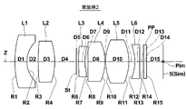
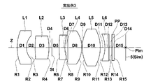
- the aperture stop St, the optical member PP, and the image sensor 5 disposed on the image plane Sim are also illustrated. Yes.
- the aperture stop St in each figure does not indicate the shape or size, but indicates the position on the optical axis Z.
- Tables 1 to 6 show lens data of the imaging lenses of Examples 1 to 6, respectively.
- (A) shows basic lens data
- (B) shows various data
- (C) shows aspheric data for those containing aspherical shapes.
- Ri column indicates the radius of curvature of the i-th surface
- Di column indicates the surface spacing on the optical axis Z between the i-th surface and the i + 1-th surface. The sign of the radius of curvature is positive when the surface shape is convex on the object side and negative when the surface shape is convex on the image side.
- the refractive index with respect to the d-line (wavelength: 587.6 nm) of the j-th (j 1, 2, 3,%) Optical element that sequentially increases toward the image side with the most object-side lens as the first.
- the column of ⁇ dj indicates the Abbe number for the d-line of the jth optical element.
- the basic lens data includes the aperture stop St and the optical member PP, and the word “St” is also written in the surface number column of the surface corresponding to the aperture stop St.
- the imaging surface is described as IMG.
- the surface number of the aspheric surface is marked with *, and the value of the paraxial curvature radius (center curvature radius) is shown as the curvature radius of the aspheric surface.
- the aspheric data shows the surface number of the aspheric surface and the aspheric coefficient for each aspheric surface.
- the numerical value “E ⁇ n” (n: integer) of the aspheric surface data means “ ⁇ 10 ⁇ n ”, and “E + n” means “ ⁇ 10 n ”.
- Zd C ⁇ h 2 / ⁇ 1+ (1 ⁇ KA ⁇ C 2 ⁇ h 2 ) 1/2 ⁇ + ⁇ RBm ⁇ h m
- Zd Depth of aspheric surface (length of a perpendicular line drawn from a point on the aspherical surface at height h to a plane perpendicular to the optical axis where the aspherical vertex contacts)
- h Height (distance from the optical axis to the lens surface)
- C Reciprocal number KA of paraxial curvature radius
- L (in Air) is the distance on the optical axis Z from the object-side surface of the first lens L1 to the image plane Sim (the back focus is the air equivalent length), and Bf (in Air) is the most image side.
- the distance on the optical axis Z from the image side surface of the lens to the image plane Sim (corresponding to back focus, air conversion length) f is the focal length of the entire system
- f2 is the focal length of the second lens L2
- f3 is The focal length of the third lens L3, f4 is the focal length of the fourth lens L4
- f34 is the combined focal length of the third lens L3 and the fourth lens L4
- f45 is the combined focal length of the fourth lens L4 and the fifth lens L5.
- the distance, f56, is the combined focal length of the fifth lens L5 and the sixth lens L6.
- Conditional expression (1) is (R3F + R3R) / (R3F-R3R)
- conditional expression (2) is ⁇ d3
- conditional expression (3) is f3 / f
- conditional expression (4) is f2 / f
- conditional expression (5 ) Is f4 / f
- conditional expression (6) is ⁇ d4 / ⁇ d5
- conditional expression (7) is f34 / f
- conditional expression (8) is ⁇ d1 / ⁇ d2
- conditional expression (9) is L / f
- conditional expression (10 ) Is Bf / f
- conditional expression (11) is f45 / f
- conditional expression (12) is f56 / f.
- R3F radius of curvature of the object side surface of the third lens L3
- R3R radius of curvature of the image side surface of the third lens L3 f2: focal length of the second lens L2
- f4 focal length of the fourth lens L4 f34: third
- the combined focal length f45 of the lens L3 and the fourth lens L4 The combined focal length f56 of the fourth lens L4 and the fifth lens L5: The combined focal length f5 of the fifth lens L5 and the sixth lens L6:
- Abbe number ⁇ d5 with respect to the line Abbe number L with respect to the d line of the material of the fifth lens L5: Distance from the
- the lens material is glass.
- Tables 1 to 6 the lens material names are described, but other materials having similar characteristics may be used.
- HOYA's TAFD25 is described, but other companies' materials having equivalent properties may be used.
- Ohara L-LAH86, Chengdu Komyo H-ZLAF75A, etc. may be used.
- Ohara S-NPH2 is described as the lens material, for example, Chengdu Komeisha H-ZF72A may be used.
- Ohara S-LAH58 is described as the lens material
- HOYA TAFD30 Sumita K-LASFN17, Chengdu Komeisha H-ZLAF68, etc. may be used.
- Ohara S-LAH66 is described as the lens material, HOYA TAF1, Sumita K-LAFK50, Chengdu Komei H-LAF50B, etc. may be used.
- Ohara S-PHM52 is described as the lens material, HOYA PCD4, Sumita K-PSKN2, Chengdu Komei H-ZPK1, etc. may be used.
- Ohara L-LAH53 is described as the lens material
- HOYA NBFD13, M-NBFD130, Sumita K-LASFN1, Chengdu Komeisha H-ZLAF52, etc. may be used.
- Ohara S-YGH51 is described as the lens material
- HOYA TAC6, Sumita K-LASKN1, Chengdu Komeisha H-LAK53A, etc. may be used.
- the first lens L1 to the sixth lens L6 are all made of glass, but plastic may be used. In this case, each lens can be manufactured at low cost.
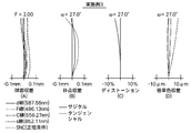
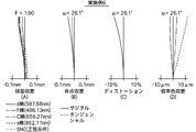
- FIGS. 8A to 13D Aberration diagrams of the imaging lenses according to Examples 1 to 6 are shown in FIGS. 8A to 13D, respectively.
- Example 1 the aberration diagram of Example 1 will be described as an example, but the same applies to the aberration diagrams of other Examples.
- 8A, FIG. 8B, FIG. 8C, and FIG. 8D are the spherical aberration, astigmatism, distortion (distortion aberration), and lateral chromatic aberration of the imaging lens according to Example 1, respectively.
- the aberration diagram of chromatic aberration of magnification) is shown.
- F in the spherical aberration diagram means F value
- ⁇ in other aberration diagrams means half angle of view.
- the distortion diagram shows the amount of deviation from the ideal image height f ⁇ tan ( ⁇ ) using the focal length f and angle of view ⁇ (variable treatment, 0 ⁇ ⁇ ⁇ ⁇ ) of the entire system.
- Each aberration diagram shows aberrations with the d-line (587.56 nm) as the reference wavelength, while the spherical aberration diagram shows the F-line (wavelength 486.13 nm), C-line (wavelength 656.27 nm), and s-line ( Aberrations for wavelength 852.11 nm) and sine condition violation amounts (denoted as SNC) are also shown, and the chromatic aberration diagram for magnification shows aberrations for F-line, C-line, and s-line. Since the line type of the chromatic aberration diagram of magnification is the same as that of the spherical aberration diagram, the description is omitted.
- the imaging lenses of Examples 1 to 6 are configured with as few as six lenses, and can be made small and inexpensive, and the F value is as small as 1.8 to 2.0. Each aberration is corrected satisfactorily and has good optical performance.
- These imaging lenses can be suitably used for surveillance cameras, in-vehicle cameras for taking images of the front, side, rear, etc. of automobiles.
- FIG. 14 illustrates a state in which an imaging apparatus including the imaging lens of the present embodiment is mounted on the automobile 100.
- an automobile 100 includes an in-vehicle camera 101 for imaging a blind spot range on the side surface on the passenger seat side, an in-vehicle camera 102 for imaging a blind spot range on the rear side of the automobile 100, and a rear surface of a rearview mirror.
- An in-vehicle camera 103 is attached and is used for photographing the same field of view as the driver.
- the vehicle exterior camera 101, the vehicle exterior camera 102, and the vehicle interior camera 103 are imaging devices according to embodiments of the present invention, and convert an imaging lens according to an embodiment of the present invention and an optical image formed by the imaging lens into an electrical signal.
- An image pickup device An image pickup device.
- the outside cameras 101 and 102 and the inside camera 103 can also be configured to be small and inexpensive, have a wide angle of view, and have an imaging region peripheral portion. A good image can be obtained.
- the present invention has been described with reference to the embodiments and examples. However, the present invention is not limited to the above-described embodiments and examples, and various modifications can be made.
- the values of the radius of curvature, the surface interval, the refractive index, and the Abbe number of each lens component are not limited to the values shown in the above numerical examples, and can take other values.
- all the lenses are made of a homogeneous material, but a gradient index lens may be used.
- a gradient index lens may be used.
- the present invention is not limited to this application, and for example, a mobile terminal camera or a surveillance camera The present invention can also be applied.
Landscapes
- Physics & Mathematics (AREA)
- General Physics & Mathematics (AREA)
- Optics & Photonics (AREA)
- Lenses (AREA)
Abstract
Description
νd3<30.0 … (2)
ただし、
R3F:第3レンズの物体側の面の曲率半径
R3R:第3レンズの像側の面の曲率半径
νd3:第3レンズの材質のd線に対するアッベ数
本発明の第2の撮像レンズは、物体側から順に、負のパワーを持つ第1レンズ、正のパワーを持つ第2レンズ、負のパワーを持つ第3レンズ、正のパワーを持つ第4レンズ、正のパワーを持つ第5レンズおよび負のパワーを持つ第6レンズからなり、下記条件式を満足することを特徴とするものである。
ただし、
R3F:第3レンズの物体側の面の曲率半径
R3R:第3レンズの像側の面の曲率半径
本発明の第3の撮像レンズは、物体側から順に、負のパワーを持つ第1レンズ、正のパワーを持つ第2レンズ、負のパワーを持つ第3レンズ、正のパワーを持つ第4レンズ、正のパワーを持つ第5レンズおよび負のパワーを持つ第6レンズからなり、下記条件式を満足することを特徴とするものである。
f3/f<-1.4 … (3)
ただし、
νd3:第3レンズの材質のd線に対するアッベ数
f3:第3レンズの焦点距離
f:全系の焦点距離
なお、本発明の第1の撮像レンズは第2および第3の撮像レンズの少なくとも一方の構成を有するものであってもよく、本発明の第2の撮像レンズは第1および第3の撮像レンズの少なくとも一方の構成を有するものであってもよく、本発明の第3の撮像レンズは第1および第2の撮像レンズの少なくとも一方の構成を有するものであってもよい。
1.0<f4/f … (5)
0.15<νd4/νd5<3.0 … (6)
1.5<f34/f<5.0 … (7)
0.3<νd1/νd2<2.5 … (8)
2.0<L/f<10.0 … (9)
0.2<Bf/f<2.0 … (10)
0.2<f45/f<3.0 … (11)
1.5<f56/f<7.5 … (12)
ただし、
f2:第2レンズの焦点距離
f4:第4レンズの焦点距離
f34:第3レンズおよび第4レンズの合成焦点距離
f45:第4レンズおよび第5レンズの合成焦点距離
f56:第5レンズおよび第6レンズの合成焦点距離
f:全系の焦点距離
νd1:第1レンズの材質のd線に対するアッベ数
νd2:第2レンズの材質のd線に対するアッベ数
νd4:第4レンズの材質のd線に対するアッベ数
νd5:第5レンズの材質のd線に対するアッベ数
L:第1レンズの物体側の面から像面までの距離(バックフォーカス分は空気換算長)
Bf:最も像側のレンズの像側の面から撮像素子までの距離(バックフォーカス、空気換算長)
本発明の撮像装置は、上記記載の本発明の第1から第3の撮像レンズの少なくともいずれか1つを搭載したことを特徴とするものである。
まず、図1を参照しながら、本発明の実施形態に係る撮像レンズについて説明する。図1は、本発明の実施形態に係る撮像レンズ1の構成と光路を示す図である。なお、図1に示す撮像レンズ1は後述する本発明の実施例1に係る撮像レンズに対応するものである。
νd3<30.0 … (2)
ただし、
R3F:第3レンズL3の物体側の面の曲率半径
R3R:第3レンズL3の像側の面の曲率半径
νd3:第3レンズL3の材質のd線に対するアッベ数
第1の実施形態の撮像レンズは、最小6枚という少ないレンズ枚数で構成し、全系におけるパワー配置等を好適に設定することで、低コスト化とともに光軸方向の全長の小型化を図ることができる。また、最も物体側のレンズである第1レンズL1を負のパワーを持つレンズとすることで、レンズ系を広角化でき、かつバックフォーカスの確保が容易となり、レンズ系の径方向の小型化も容易となる。
ただし、
R3F:第3レンズL3の物体側の面の曲率半径
R3R:第3レンズL3の像側の面の曲率半径
第2の実施形態の撮像レンズは、最小6枚という少ないレンズ枚数で構成し、全系におけるパワー配置等を好適に設定することで、低コスト化とともに光軸方向の全長の小型化を図ることができる。また、最も物体側のレンズである第1レンズL1を負のパワーを持つレンズとすることで、レンズ系を広角化でき、かつバックフォーカスの確保が容易となり、レンズ系の径方向の小型化も容易となる。
f3/f<-1.4 … (3)
ただし、
νd3:第3レンズL3の材質のd線に対するアッベ数
f3:第3レンズL3の焦点距離
f:全系の焦点距離
第3の実施形態の撮像レンズは、最小6枚という少ないレンズ枚数で構成し、全系におけるパワー配置等を好適に設定することで、低コスト化とともに光軸方向の全長の小型化を図ることができる。また、最も物体側のレンズである第1レンズL1を負のパワーを持つレンズとすることで、レンズ系を広角化でき、かつバックフォーカスの確保が容易となり、レンズ系の径方向の小型化も容易となる。
1.0<f4/f … (5)
0.15<νd4/νd5<3.0 … (6)
1.5<f34/f<5.0 … (7)
0.3<νd1/νd2<2.5 … (8)
2.0<L/f<10.0 … (9)
0.2<Bf/f<2.0 … (10)
0.2<f45/f<3.0 … (11)
1.5<f56/f<7.5 … (12)
ただし、
f2:第2レンズL2の焦点距離
f4:第4レンズL4の焦点距離
f34:第3レンズL3および第4レンズL4の合成焦点距離
f45:第4レンズL4および第5レンズL5の合成焦点距離
f56:第5レンズL5および第6レンズL6の合成焦点距離
f:全系の焦点距離
νd1:第1レンズL1の材質のd線に対するアッベ数
νd2:第2レンズL2の材質のd線に対するアッベ数
νd4:第4レンズL4の材質のd線に対するアッベ数
νd5:第5レンズL5の材質のd線に対するアッベ数
L:第1レンズL1の物体側の面から像面までの距離(バックフォーカス分は空気換算長)
Bf:最も像側のレンズの像側の面から撮像素子までの距離(バックフォーカス、空気換算長)
条件式(4)の下限を満足することで、第2レンズL2のパワーが強くなりすぎるのを抑えることができ、偏心による誤差感度を抑えることが容易となる。
1.35<(R3F+R3R)/(R3F-R3R)<3.3 … (1-2)
1.4<(R3F+R3R)/(R3F-R3R)<2.20 … (1-3)
1.35<(R3F+R3R)/(R3F-R3R)<6.0 … (1-4)
1.35<(R3F+R3R)/(R3F-R3R)<4.2 … (1-5)
1.5<(R3F+R3R)/(R3F-R3R)<2.0 … (1-6)
条件式(2)の上限は25とすることが好ましく、これにより、第3レンズL3の材質のd線に対するアッベ数を小さくすることがより容易となり、軸上の色収差の補正がより容易となる。条件式(2)の上限は22とすることがより好ましく、20とすることがさらに好ましい。上記より、例えば下記条件式(2-1)~(2-3)を満足することがより好ましい。
νd3<20.0 … (2-2)
νd3<19.0 … (2-3)
条件式(3)の上限は-1.6とすることが好ましく、これにより、球面収差および像面湾曲の補正がより容易となる。条件式(3)の上限は-1.8とすることがより好ましく、-1.9とすることがさらに好ましい。条件式(3)に下限を設けることが好ましく、下限は-10とすることが好ましく、これにより、第3レンズL3のパワーを強くすることが容易となり、軸上の色収差の補正が容易となる。条件式(3)の下限は-5とすることが好ましく、-4とすることがより好ましく、-3.8とすることがさらに好ましい。上記より、例えば下記条件式(3-1)~(3-5)を満足することがより好ましい。
f3/f<-1.8 … (3-2)
-10<f3/f<-1.4 … (3-3)
-5<f3/f<-1.6 … (3-4)
-4/f3/f<-1.8 … (3-5)
条件式(4)の下限は1.1とすることが好ましく、これにより、第2レンズL2のパワーが強くなりすぎるのをより抑えることができ、偏心による誤差感度を抑えることがより容易となる。条件式(4)の下限は1.2とすることがより好ましく、1.3とすることがさらに好ましい。条件式(4)に上限を設けることが好ましく、上限は10.0とすることが好ましく、これにより、第2レンズL2のパワーを強くすることが容易となり、像面湾曲の補正が容易となる。条件式(4)の上限は8.0とすることが好ましく、6.0とすることがより好ましく、5.0とすることがさらに好ましく、4.0とすることがさらにより好ましい。上記より、例えば下記条件式(4-1)~(4-4)を満足することがより好ましい。
1.1<f2/f<6.0 … (4-2)
1.2<f2/f<5.0 … (4-3)
1.1<f2/f<4.0 … (4-4)
条件式(5)の下限は1.1とすることが好ましく、これにより、第4レンズL4のパワーが強くなりすぎるのをより抑えることができ、偏心による誤差感度を抑えることがより容易となり、かつ第4レンズL4のパワーを抑えることがより容易となり、球面収差の補正がより容易となる。条件式(5)の下限は1.2とすることがより好ましく、1.3とすることがさらに好ましい。条件式(5)に上限を設けることが好ましく、上限は7.0とすることが好ましく、これにより、球面収差および像面湾曲の補正が容易となる。条件式(5)の上限は5.0とすることが好ましく、4.1とすることがより好ましく、3.3とすることがさらに好ましく、2.1とすることがさらにより好ましい。上記より、例えば下記条件式(5-1)~(5-4)を満足することがより好ましい。
1.1<f4/f<5.0 … (5-2)
1.2<f4/f<5.0 … (5-3)
1.1<f4/f<3.3 … (5-4)
条件式(6)の上限は2.0とすることが好ましく、これにより、第5レンズL5の材質のd線に対するアッベ数を大きくすることがより容易となり、軸上の色収差および倍率の色収差を抑えることがより容易となる。条件式(6)の上限は1.0とすることがより好ましく、0.9とすることがさらに好ましい。条件式(6)の下限は0.2とすることが好ましく、これにより、第4レンズL4の材質のd線に対するアッベ数が小さくなるのを抑えることがより容易となり、軸上の色収差および倍率の色収差を抑えることがより容易となる。条件式(6)の下限は0.4とすることがより好ましく、0.5とすることがさらに好ましい。上記より、例えば下記条件式(6-1)~(6-4)を満足することがより好ましい。
0.4<νd4/νd5<1.0 … (6-2)
0.5<νd4/νd5<1.0 … (6-3)
0.5<νd4/νd5<0.9 … (6-4)
条件式(7)の上限は4.7とすることが好ましく、これにより、第3レンズL3および第4レンズL4の合成パワーが弱くなるのを抑えることがより容易となり、球面収差を抑えることがより容易となる。条件式(7)の上限は4.2とすることがより好ましく、3.9とすることがさらに好ましい。条件式(7)の下限は1.7とすることが好ましく、これにより、第3レンズL3および第4レンズL4の合成パワーが強くなるのを抑えることがより容易となり、像面湾曲を抑えることがより容易となる。条件式(7)の下限は1.8とすることがより好ましく、1.9とすることがさらに好ましい。上記より、例えば下記条件式(7-1)~(7-4)を満足することがより好ましい。
1.8<f34/f<4.2 … (7-2)
1.8<f34/f<3.9 … (7-3)
1.9<f34/f<3.9 … (7-4)
条件式(8)の上限は2.2とすることが好ましく、これにより、第2レンズL2の材質のd線に対するアッベ数が小さくなりすぎるのを抑えることがより容易となり、軸上の色収差を抑えることがより容易となる。条件式(8)の上限は1.8とすることがより好ましく、1.5とすることがさらに好ましい。条件式(8)の下限は0.4とすることが好ましく、これにより、第1レンズL1の材質のd線に対するアッベ数を大きくすることがより容易となり、軸上の色収差および倍率の色収差を抑えることがより容易となるか、第2レンズL2の材質のd線に対するアッベ数を小さくすることがより容易となり、倍率の色収差を抑えることがより容易となる。条件式(8)の下限は0.6とすることがより好ましい。上記より、例えば下記条件式(8-1)~(8-3)を満足することがより好ましい。
0.4<νd1/νd2<1.8 … (8-2)
0.6<νd1/νd2<1.5 … (8-3)
条件式(9)の上限は9.0とすることが好ましく、これにより、レンズ系の小型化がより容易となるか、広角化がより容易となる。条件式(9)の上限は7.0とすることがより好ましく、6.0とすることがさらに好ましい。条件式(9)の下限は2.5とすることが好ましく、これにより、各レンズの厚さを厚くすることがより容易となり、レンズの加工および組立てがより容易となる。条件式(9)の下限は3.0とすることがより好ましい。上記より、例えば下記条件式(9-1)~(9-3)を満足することがより好ましい。
2.5<L/f<7.0 … (9-2)
3.0<L/f<6.0 … (9-3)
条件式(10)の上限は1.8とすることが好ましく、これにより、バックフォーカスを抑えることがより容易となり、レンズ系の小型化がより容易となる。条件式(10)の上限は1.6とすることがより好ましく、1.4とすることがさらに好ましい。条件式(10)の下限は0.3とすることが好ましく、これにより、バックフォーカスを長くすることがより容易となり、レンズ系との間に各種フィルタやカバーガラスを配置することがより容易となる。条件式(10)の下限は0.4とすることがより好ましい。上記より、例えば下記条件式(10-1)~(10-3)を満足することがより好ましい。
0.3<Bf/f<1.6 … (10-2)
0.4<Bf/f<1.4 … (10-3)
条件式(11)の上限は2.2とすることが好ましく、これにより、第4レンズL4および第5レンズL5の合成パワーが弱くなりすぎるのを抑えることがより容易となり、球面収差の補正がより容易となるか、倍率の色収差の補正がより容易となる。条件式(11)の上限は1.6とすることがより好ましく、1.3とすることがさらに好ましい。条件式(11)の下限は0.3とすることが好ましく、これにより、第4レンズL4および第5レンズL5の合成パワーが強くなりすぎるを抑えることがより容易となり、バックフォーカスの確保がより容易となる。条件式(11)の下限は0.4とすることがより好ましい。上記より、例えば下記条件式(11-1)~(11-4)を満足することがより好ましい。
0.3<f45/f<1.6 … (11-2)
0.3<f45/f<1.3 … (11-3)
0.4/f45/f<1.3 … (11-4)
条件式(12)の上限は6.0とすることが好ましく、これにより、第6レンズL6のパワーが強くなるのを抑えることがより容易となり、光線が撮像素子に入射する角度を抑えることがより容易となるか、第5レンズL5のパワーが弱くなるのを抑えることがより容易となり、球面収差の補正がより容易となる。条件式(12)の上限は5.5とすることがより好ましく、5.0とすることがさらに好ましい。条件式(12)の下限は2.0とすることが好ましく、これにより、第6レンズL6のパワーが弱くなるのを抑えることがより容易となり、倍率の色収差の補正がより容易となるか、第5レンズL5のパワーが強くなりすぎるのを防ぐことで、球面収差の補正がより容易となるかバックフォーカスの確保がより容易となる。条件式(12)の下限は2.2とすることがより好ましく、2.5とすることがさらに好ましい。上記より、例えば下記条件式(12-1)~(12-3)を満足することがより好ましい。
2.2<f56/f<5.5 … (12-2)
2.5<f56/f<5.0 … (12-3)
レンズ系のうち正のパワーを持つレンズに、屈折率の温度係数dn/dtが負の値となる材質を使用することが好ましい。これにより、温度変化によるフォーカスシフトを抑えることが容易となる。屈折率の温度係数dn/dtが負の値となる材質は1枚のレンズのみに使用されていてもよく、複数枚のレンズに使用されていてもよい。
次に、本発明の撮像レンズの数値実施例について説明する。実施例1~実施例6の撮像レンズのレンズ断面図をそれぞれ図2~図7に示す。図2~図7において、図の左側が物体側、右側が像側であり、図1と同様、開口絞りSt、光学部材PP、像面Simに配置された撮像素子5も併せて図示している。各図の開口絞りStは形状や大きさを表すものではなく、光軸Z上の位置を示すものである。各実施例において、レンズ断面図の符号Ri、Di(i=1、2、3、…)は以下に説明するレンズデータのRi、Diと対応している。
ただし、
Zd:非球面深さ(高さhの非球面上の点から、非球面頂点が接する光軸に垂直な平面に下ろした垂線の長さ)
h:高さ(光軸からのレンズ面までの距離)
C:近軸曲率半径の逆数
KA、RBm:非球面係数(m=3、4、5、…20)
各種データにおいて、L(in Air)は第1レンズL1の物体側の面から像面Simまでの光軸Z上の距離(バックフォーカス分は空気換算長)、Bf(in Air)は最も像側のレンズの像側の面から像面Simまでの光軸Z上の距離(バックフォーカスに相当、空気換算長)、fは全系の焦点距離、f2は第2レンズL2の焦点距離、f3は第3レンズL3の焦点距離、f4は第4レンズL4の焦点距離、f34は第3レンズL3と第4レンズL4との合成焦点距離、f45は第4レンズL4と第5レンズL5との合成焦点距離、f56は第5レンズL5と第6レンズL6との合成焦点距離である。
R3F:第3レンズL3の物体側の面の曲率半径
R3R:第3レンズL3の像側の面の曲率半径
f2:第2レンズL2の焦点距離
f4:第4レンズL4の焦点距離
f34:第3レンズL3および第4レンズL4の合成焦点距離
f45:第4レンズL4および第5レンズL5の合成焦点距離
f56:第5レンズL5および第6レンズL6の合成焦点距離
f:全系の焦点距離
νd1:第1レンズL1の材質のd線に対するアッベ数
νd2:第2レンズL2の材質のd線に対するアッベ数
νd3:第3レンズL3の材質のd線に対するアッベ数
νd4:第4レンズL4の材質のd線に対するアッベ数
νd5:第5レンズL5の材質のd線に対するアッベ数
L:第1レンズL1の物体側の面から像面までの距離
Bf:最も像側のレンズの像側の面から撮像素子までの距離(バックフォーカス)
各数値の単位として、長さについては「mm」を用いているが、これは一例であり、光学系は比例拡大または比例縮小しても使用可能なため、他の適当な単位を用いることもできる。

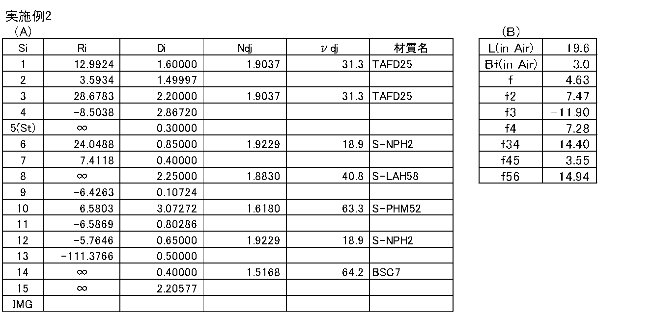

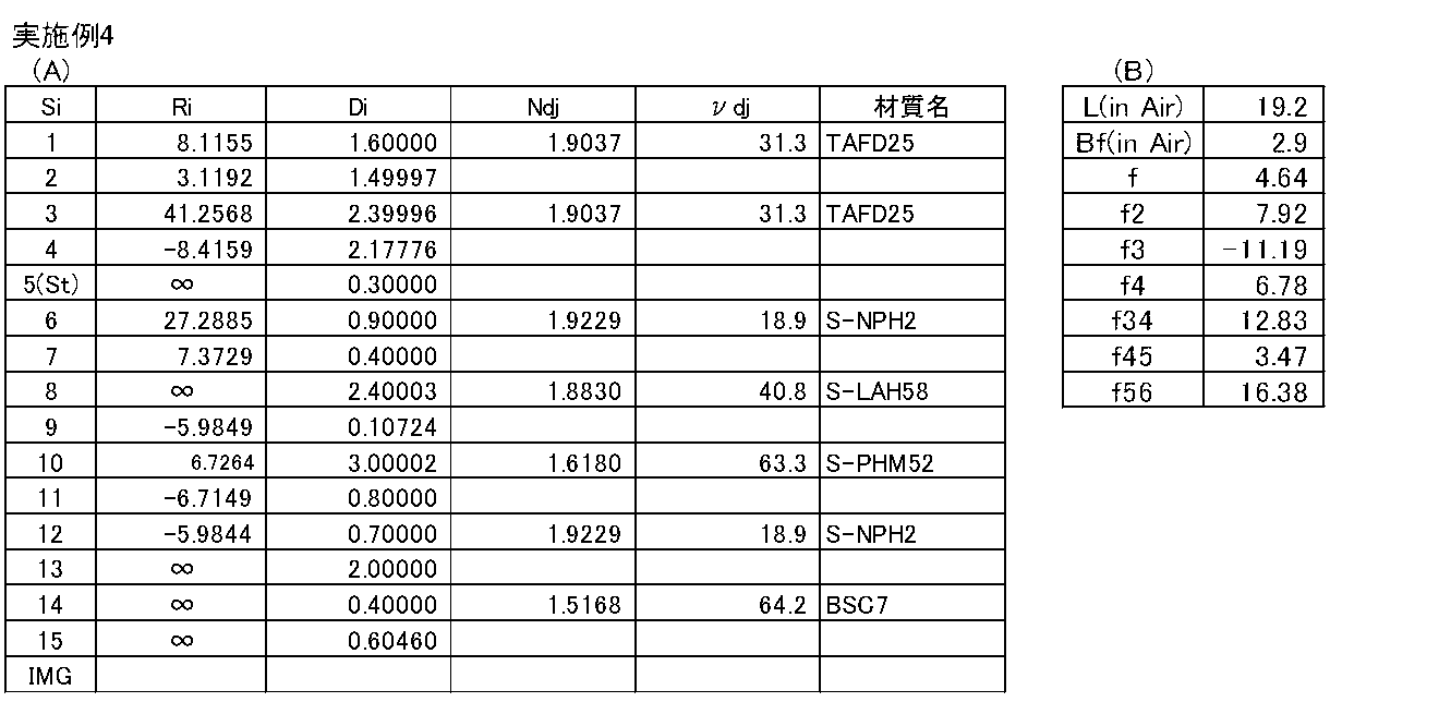
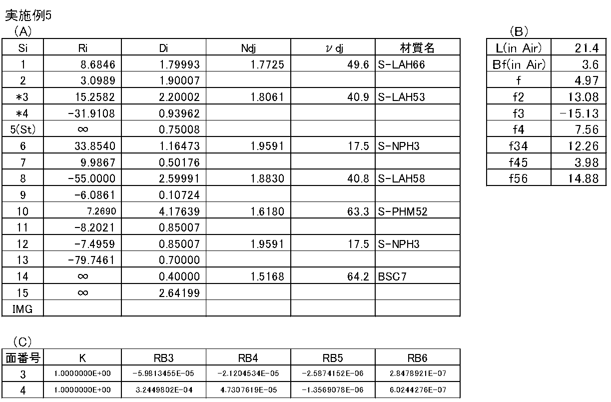

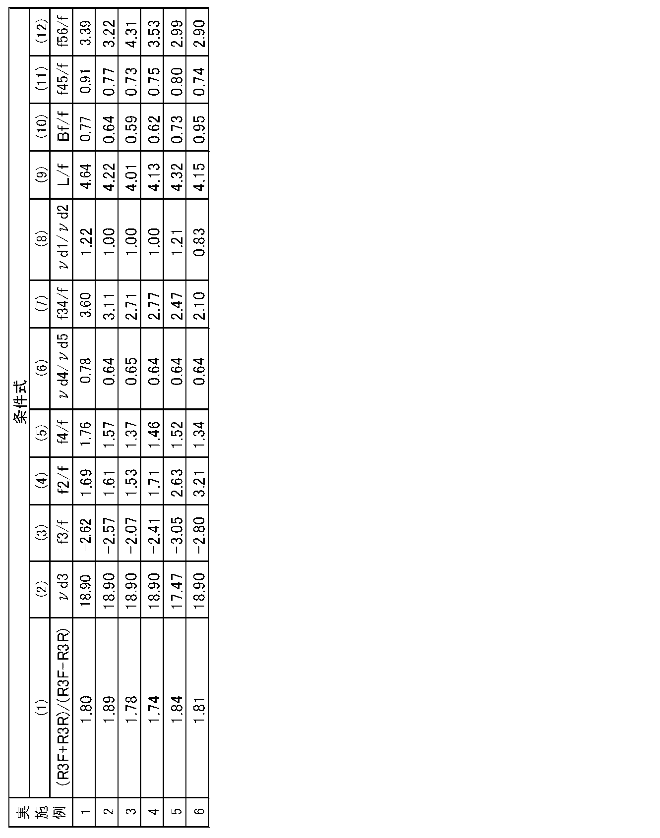
上記実施例1~6に係る撮像レンズの各収差図をそれぞれ、図8~図13の(A)~(D)に示す。
図14に使用例として、自動車100に本実施形態の撮像レンズを備えた撮像装置を搭載した様子を示す。図14において、自動車100は、その助手席側の側面の死角範囲を撮像するための車外カメラ101と、自動車100の後側の死角範囲を撮像するための車外カメラ102と、ルームミラーの背面に取り付けられ、ドライバーと同じ視野範囲を撮影するための車内カメラ103とを備えている。車外カメラ101と車外カメラ102と車内カメラ103とは、本発明の実施形態に係る撮像装置であり、本発明の実施例の撮像レンズと、この撮像レンズにより形成される光学像を電気信号に変換する撮像素子とを備えている。
Claims (19)
- 物体側から順に、負のパワーを持つ第1レンズ、正のパワーを持つ第2レンズ、負のパワーを持つ第3レンズ、正のパワーを持つ第4レンズ、正のパワーを持つ第5レンズおよび負のパワーを持つ第6レンズからなり、下記条件式を満足することを特徴とする撮像レンズ。
1.35<(R3F+R3R)/(R3F-R3R)<6.0 … (1)
νd3<30.0 … (2)
ただし、
R3F:前記第3レンズの物体側の面の曲率半径
R3R:前記第3レンズの像側の面の曲率半径
νd3:前記第3レンズの材質のd線に対するアッベ数 - 物体側から順に、負のパワーを持つ第1レンズ、正のパワーを持つ第2レンズ、負のパワーを持つ第3レンズ、正のパワーを持つ第4レンズ、正のパワーを持つ第5レンズおよび負のパワーを持つ第6レンズからなり、下記条件式を満足することを特徴とする撮像レンズ。
1.35<(R3F+R3R)/(R3F-R3R)<2.20 … (1-1)
ただし、
R3F:前記第3レンズの物体側の面の曲率半径
R3R:前記第3レンズの像側の面の曲率半径 - 物体側から順に、負のパワーを持つ第1レンズ、正のパワーを持つ第2レンズ、負のパワーを持つ第3レンズ、正のパワーを持つ第4レンズ、正のパワーを持つ第5レンズおよび負のパワーを持つ第6レンズからなり、下記条件式を満足することを特徴とする撮像レンズ。
νd3<30.0 … (2)
f3/f<-1.4 … (3)
ただし、
νd3:前記第3レンズの材質のd線に対するアッベ数
f3:前記第3レンズの焦点距離
f:全系の焦点距離 - 下記条件式を満足する請求項1から3のいずれか1項記載の撮像レンズ。
1.0<f2/f … (4)
ただし、
f2:前記第2レンズの焦点距離
f:全系の焦点距離 - 下記条件式を満足する請求項1から4のいずれか1項記載の撮像レンズ。
1.0<f4/f … (5)
ただし、
f4:前記第4レンズの焦点距離
f:全系の焦点距離 - 下記条件式を満足する請求項1から5のいずれか1項記載の撮像レンズ。
0.15<νd4/νd5<3.0 … (6)
ただし、
νd4:前記第4レンズの材質のd線に対するアッベ数
νd5:前記第5レンズの材質のd線に対するアッベ数 - レンズ系のうち正のパワーを持つレンズに、屈折率の温度係数dn/dtが負の値となる材質を使用した請求項1から6のいずれか1項記載の撮像レンズ。
- 下記条件式を満足する請求項1から7のいずれか1項記載の撮像レンズ。
1.5<f34/f<5.0 … (7)
ただし、
f34:前記第3レンズおよび前記第4レンズの合成焦点距離
f:全系の焦点距離 - 下記条件式を満足する請求項1から8のいずれか1項記載の撮像レンズ。
0.3<νd1/νd2<2.5 … (8)
ただし、
νd1:前記第1レンズの材質のd線に対するアッベ数
νd2:前記第2レンズの材質のd線に対するアッベ数 - さらに下記条件式を満足する請求項1記載の撮像レンズ。
1.35<(R3F+R3R)/(R3F-R3R)<3.3 … (1-2)
ただし、
R3F:前記第3レンズの物体側の面の曲率半径
R3R:前記第3レンズの像側の面の曲率半径 - さらに下記条件式を満足する請求項1または2記載の撮像レンズ。
1.4<(R3F+R3R)/(R3F-R3R)<2.20 … (1-3)
ただし、
R3F:前記第3レンズの物体側の面の曲率半径
R3R:前記第3レンズの像側の面の曲率半径 - さらに下記条件式を満足する請求項1または3記載の撮像レンズ。
νd3<20.0 … (2-2)
ただし、
νd3:前記第3レンズの材質のd線に対するアッベ数 - さらに下記条件式を満足する請求項3記載の撮像レンズ。
-5<f3/f<-1.6 … (3-4)
ただし、
f3:前記第3レンズの焦点距離
f:全系の焦点距離 - さらに下記条件式を満足する請求項4記載の撮像レンズ。
1.1<f2/f<6.0 … (4-2)
ただし、
f2:前記第2レンズの焦点距離
f:全系の焦点距離 - さらに下記条件式を満足する請求項5記載の撮像レンズ。
1.1<f4/f<5.0 … (5-2)
ただし、
f4:前記第4レンズの焦点距離
f:全系の焦点距離 - さらに下記条件式を満足する請求項8記載の撮像レンズ。
1.7<f34/f<4.7 … (7-1)
ただし、
f34:前記第3レンズおよび前記第4レンズの合成焦点距離
f:全系の焦点距離 - さらに下記条件式を満足する請求項8記載の撮像レンズ。
1.8<f34/f<3.9 … (7-3)
ただし、
f34:前記第3レンズおよび前記第4レンズの合成焦点距離
f:全系の焦点距離 - さらに下記条件式を満足する請求項9記載の撮像レンズ。
0.4<νd1/νd2<1.8 … (8-1)
ただし、
νd1:前記第1レンズの材質のd線に対するアッベ数
νd2:前記第2レンズの材質のd線に対するアッベ数 - 請求項1記載の撮像レンズを搭載した撮像装置。
Priority Applications (4)
| Application Number | Priority Date | Filing Date | Title |
|---|---|---|---|
| JP2015507698A JP5869727B2 (ja) | 2013-03-27 | 2013-12-26 | 撮像レンズおよび撮像装置 |
| CN201380074870.7A CN105143948B (zh) | 2013-03-27 | 2013-12-26 | 摄像透镜及摄像装置 |
| DE112013006876.1T DE112013006876B4 (de) | 2013-03-27 | 2013-12-26 | Abbildungsobjektiv und Abbildungsvorrichtung |
| US14/857,205 US9632288B2 (en) | 2013-03-27 | 2015-09-17 | Imaging lens and imaging apparatus |
Applications Claiming Priority (2)
| Application Number | Priority Date | Filing Date | Title |
|---|---|---|---|
| JP2013066444 | 2013-03-27 | ||
| JP2013-066444 | 2013-03-27 |
Related Child Applications (1)
| Application Number | Title | Priority Date | Filing Date |
|---|---|---|---|
| US14/857,205 Continuation US9632288B2 (en) | 2013-03-27 | 2015-09-17 | Imaging lens and imaging apparatus |
Publications (1)
| Publication Number | Publication Date |
|---|---|
| WO2014155464A1 true WO2014155464A1 (ja) | 2014-10-02 |
Family
ID=51622563
Family Applications (1)
| Application Number | Title | Priority Date | Filing Date |
|---|---|---|---|
| PCT/JP2013/007608 Ceased WO2014155464A1 (ja) | 2013-03-27 | 2013-12-26 | 撮像レンズおよび撮像装置 |
Country Status (5)
| Country | Link |
|---|---|
| US (1) | US9632288B2 (ja) |
| JP (1) | JP5869727B2 (ja) |
| CN (1) | CN105143948B (ja) |
| DE (1) | DE112013006876B4 (ja) |
| WO (1) | WO2014155464A1 (ja) |
Cited By (8)
| Publication number | Priority date | Publication date | Assignee | Title |
|---|---|---|---|---|
| JP2017102183A (ja) * | 2015-11-30 | 2017-06-08 | 富士フイルム株式会社 | 撮像レンズおよび撮像装置 |
| JP2017102182A (ja) * | 2015-11-30 | 2017-06-08 | 富士フイルム株式会社 | 撮像レンズおよび撮像装置 |
| CN108227140A (zh) * | 2017-12-29 | 2018-06-29 | 瑞声科技(新加坡)有限公司 | 摄像光学镜头 |
| JP2019120906A (ja) * | 2017-12-29 | 2019-07-22 | エーエーシー テクノロジーズ ピーティーイー リミテッドAac Technologies Pte.Ltd. | 撮像光学レンズ |
| JP2019120920A (ja) * | 2017-12-29 | 2019-07-22 | エーエーシー テクノロジーズ ピーティーイー リミテッドAac Technologies Pte.Ltd. | 撮像光学レンズ |
| JP2019120913A (ja) * | 2017-12-29 | 2019-07-22 | エーエーシー テクノロジーズ ピーティーイー リミテッドAac Technologies Pte.Ltd. | 撮像光学レンズ |
| JP2021047346A (ja) * | 2019-09-20 | 2021-03-25 | 日本電産コパル株式会社 | 撮像レンズ及び撮像装置 |
| US12228708B2 (en) * | 2022-03-17 | 2025-02-18 | Canon Kabushiki Kaisha | Optical system including cemented lenses, imaging apparatus including the same, and moving apparatus including the same |
Families Citing this family (33)
| Publication number | Priority date | Publication date | Assignee | Title |
|---|---|---|---|---|
| TWI588524B (zh) * | 2015-11-27 | 2017-06-21 | 大立光電股份有限公司 | 攝像用光學鏡片組、取像裝置及電子裝置 |
| KR101823210B1 (ko) | 2015-12-28 | 2018-01-29 | 삼성전기주식회사 | 촬상 광학계 |
| TWI610090B (zh) * | 2016-06-16 | 2018-01-01 | 大立光電股份有限公司 | 光學影像鏡頭組、取像裝置及電子裝置 |
| US10890699B2 (en) * | 2016-09-07 | 2021-01-12 | Largan Precision Co., Ltd. | Optical image lens assembly, image capturing apparatus and electronic device |
| US11073638B2 (en) * | 2016-09-07 | 2021-07-27 | Largan Precision Co., Ltd. | Optical image lens assembly and plastic material thereof, image capturing apparatus and electronic device |
| TWI628460B (zh) * | 2016-10-19 | 2018-07-01 | 先進光電科技股份有限公司 | 光學成像系統 |
| KR101832627B1 (ko) * | 2016-11-25 | 2018-02-26 | 삼성전기주식회사 | 촬상 광학계 |
| US10356307B2 (en) * | 2017-09-13 | 2019-07-16 | Trw Automotive U.S. Llc | Vehicle camera system |
| JP6967924B2 (ja) * | 2017-09-25 | 2021-11-17 | ナンチャン オー−フィルム オプティカル−エレクトロニック テック カンパニー リミテッド | 結像レンズおよび光学装置 |
| US10830995B2 (en) * | 2017-12-18 | 2020-11-10 | Aac Optics Solutions Pte. Ltd. | Camera optical lens |
| US10495851B2 (en) * | 2017-12-18 | 2019-12-03 | AAC Technologies Pte. Ltd. | Camera optical lens |
| US10409039B2 (en) * | 2017-12-18 | 2019-09-10 | AAC Technologies Pte. Ltd. | Camera optical lens |
| US11353684B2 (en) * | 2017-12-18 | 2022-06-07 | Aac Optics Solutions Pte. Ltd. | Camera optical lens |
| CN108802964B (zh) * | 2017-12-28 | 2020-11-06 | 成都理想境界科技有限公司 | 一种光纤扫描投影物镜以及光纤扫描投影设备 |
| CN108254874B (zh) * | 2017-12-29 | 2020-06-16 | 瑞声光学解决方案私人有限公司 | 摄像光学镜头 |
| JP2019148615A (ja) * | 2018-02-26 | 2019-09-05 | O−FILM.Japan株式会社 | 撮像レンズおよび撮像装置 |
| CN108427184B (zh) * | 2018-05-05 | 2023-06-20 | 广东弘景光电科技股份有限公司 | 共焦化大靶面深度成像光学系统及其应用的摄像模组 |
| JP6543400B1 (ja) * | 2018-08-14 | 2019-07-10 | エーエーシー テクノロジーズ ピーティーイー リミテッド | 撮像光学レンズ |
| CN109100854B (zh) | 2018-09-05 | 2024-04-09 | 浙江舜宇光学有限公司 | 摄像镜头 |
| CN109445068B (zh) * | 2018-12-05 | 2020-02-18 | 江西联创电子有限公司 | 车载摄像镜头及成像设备 |
| CN109407279B (zh) * | 2018-12-12 | 2021-09-14 | 江西联创电子有限公司 | 广角镜头及成像设备 |
| CN110286471B (zh) * | 2019-06-30 | 2021-08-17 | 瑞声光学解决方案私人有限公司 | 摄像光学镜头 |
| CN110346907B (zh) * | 2019-06-30 | 2021-09-21 | 瑞声光学解决方案私人有限公司 | 摄像光学镜头 |
| CN110389425B (zh) * | 2019-06-30 | 2021-08-17 | 瑞声光学解决方案私人有限公司 | 摄像光学镜头 |
| CN110346905B (zh) * | 2019-06-30 | 2021-08-17 | 瑞声光学解决方案私人有限公司 | 摄像光学镜头 |
| CN110244437B (zh) * | 2019-06-30 | 2021-08-17 | 瑞声光学解决方案私人有限公司 | 摄像光学镜头 |
| DE102019213045A1 (de) * | 2019-08-29 | 2021-03-04 | Carl Zeiss Ag | Linsensystem für ein Kameraobjektiv, Kameraobjektiv und Verfahren zur Herstellung eines Linsensystems |
| CN112444939B (zh) * | 2019-08-30 | 2025-07-08 | 江西欧菲光学有限公司 | 光学系统、取像装置及电子装置 |
| CN112526706B (zh) * | 2019-09-17 | 2022-03-25 | 华为技术有限公司 | 一种镜头组、相关设备以及相关系统 |
| CN112698472B (zh) * | 2019-10-23 | 2022-05-31 | 宁波舜宇车载光学技术有限公司 | 光学镜头及电子设备 |
| CN110850558B (zh) * | 2019-12-20 | 2024-08-23 | 辽宁中蓝光电科技有限公司 | 超广角摄像镜头 |
| CN116755213A (zh) * | 2020-08-03 | 2023-09-15 | 大立光电股份有限公司 | 光学镜头、取像装置及电子装置 |
| CN114460724B (zh) * | 2021-12-30 | 2024-10-15 | 福建福光天瞳光学有限公司 | 一种近距广角高清成像镜头 |
Citations (12)
| Publication number | Priority date | Publication date | Assignee | Title |
|---|---|---|---|---|
| JPS6472112A (en) * | 1987-09-12 | 1989-03-17 | Fuji Photo Optical Co Ltd | Refraction type projection lens |
| JPH07311339A (ja) * | 1994-05-16 | 1995-11-28 | Minolta Co Ltd | コンパクトなズームレンズ |
| JPH0921952A (ja) * | 1995-07-06 | 1997-01-21 | Minolta Co Ltd | ズームレンズ |
| JPH09152549A (ja) * | 1995-11-29 | 1997-06-10 | Olympus Optical Co Ltd | ズームレンズ |
| JPH11142730A (ja) * | 1997-09-04 | 1999-05-28 | Konica Corp | 撮像レンズ |
| JPH11160618A (ja) * | 1997-11-25 | 1999-06-18 | Fuji Photo Optical Co Ltd | 温度変化補正機能付ズームレンズ |
| JP2005164839A (ja) * | 2003-12-01 | 2005-06-23 | Canon Inc | レンズ系及びそれを有する画像投影装置 |
| JP2006039259A (ja) * | 2004-07-28 | 2006-02-09 | Olympus Corp | 内視鏡対物光学系及びそれを用いた撮像装置 |
| JP2006343554A (ja) * | 2005-06-09 | 2006-12-21 | Konica Minolta Photo Imaging Inc | 撮影レンズユニット |
| JP2008116688A (ja) * | 2006-11-06 | 2008-05-22 | Sony Corp | 投射光学系および投射型画像表示装置 |
| JP2009109630A (ja) * | 2007-10-29 | 2009-05-21 | Canon Inc | ズームレンズ及びそれを有する撮像装置 |
| JP2011075646A (ja) * | 2009-09-29 | 2011-04-14 | Canon Inc | ズームレンズ |
Family Cites Families (4)
| Publication number | Priority date | Publication date | Assignee | Title |
|---|---|---|---|---|
| JPH0588085A (ja) | 1991-09-24 | 1993-04-09 | Asahi Optical Co Ltd | ズームレンズ |
| TWM356115U (en) * | 2008-08-21 | 2009-05-01 | Fujinon Corp | Photography lens and photography apparatus |
| JP5345823B2 (ja) * | 2008-10-28 | 2013-11-20 | 富士フイルム株式会社 | 撮像レンズおよびこの撮像レンズを用いた撮像装置 |
| JPWO2012086199A1 (ja) * | 2010-12-22 | 2014-05-22 | 富士フイルム株式会社 | 撮像レンズおよび撮像装置 |
-
2013
- 2013-12-26 DE DE112013006876.1T patent/DE112013006876B4/de not_active Expired - Fee Related
- 2013-12-26 WO PCT/JP2013/007608 patent/WO2014155464A1/ja not_active Ceased
- 2013-12-26 JP JP2015507698A patent/JP5869727B2/ja not_active Expired - Fee Related
- 2013-12-26 CN CN201380074870.7A patent/CN105143948B/zh active Active
-
2015
- 2015-09-17 US US14/857,205 patent/US9632288B2/en active Active
Patent Citations (12)
| Publication number | Priority date | Publication date | Assignee | Title |
|---|---|---|---|---|
| JPS6472112A (en) * | 1987-09-12 | 1989-03-17 | Fuji Photo Optical Co Ltd | Refraction type projection lens |
| JPH07311339A (ja) * | 1994-05-16 | 1995-11-28 | Minolta Co Ltd | コンパクトなズームレンズ |
| JPH0921952A (ja) * | 1995-07-06 | 1997-01-21 | Minolta Co Ltd | ズームレンズ |
| JPH09152549A (ja) * | 1995-11-29 | 1997-06-10 | Olympus Optical Co Ltd | ズームレンズ |
| JPH11142730A (ja) * | 1997-09-04 | 1999-05-28 | Konica Corp | 撮像レンズ |
| JPH11160618A (ja) * | 1997-11-25 | 1999-06-18 | Fuji Photo Optical Co Ltd | 温度変化補正機能付ズームレンズ |
| JP2005164839A (ja) * | 2003-12-01 | 2005-06-23 | Canon Inc | レンズ系及びそれを有する画像投影装置 |
| JP2006039259A (ja) * | 2004-07-28 | 2006-02-09 | Olympus Corp | 内視鏡対物光学系及びそれを用いた撮像装置 |
| JP2006343554A (ja) * | 2005-06-09 | 2006-12-21 | Konica Minolta Photo Imaging Inc | 撮影レンズユニット |
| JP2008116688A (ja) * | 2006-11-06 | 2008-05-22 | Sony Corp | 投射光学系および投射型画像表示装置 |
| JP2009109630A (ja) * | 2007-10-29 | 2009-05-21 | Canon Inc | ズームレンズ及びそれを有する撮像装置 |
| JP2011075646A (ja) * | 2009-09-29 | 2011-04-14 | Canon Inc | ズームレンズ |
Cited By (10)
| Publication number | Priority date | Publication date | Assignee | Title |
|---|---|---|---|---|
| JP2017102183A (ja) * | 2015-11-30 | 2017-06-08 | 富士フイルム株式会社 | 撮像レンズおよび撮像装置 |
| JP2017102182A (ja) * | 2015-11-30 | 2017-06-08 | 富士フイルム株式会社 | 撮像レンズおよび撮像装置 |
| CN106842499A (zh) * | 2015-11-30 | 2017-06-13 | 富士胶片株式会社 | 摄像透镜以及摄像装置 |
| CN106842499B (zh) * | 2015-11-30 | 2020-10-02 | 天津欧菲光电有限公司 | 摄像透镜以及摄像装置 |
| CN108227140A (zh) * | 2017-12-29 | 2018-06-29 | 瑞声科技(新加坡)有限公司 | 摄像光学镜头 |
| JP2019120906A (ja) * | 2017-12-29 | 2019-07-22 | エーエーシー テクノロジーズ ピーティーイー リミテッドAac Technologies Pte.Ltd. | 撮像光学レンズ |
| JP2019120920A (ja) * | 2017-12-29 | 2019-07-22 | エーエーシー テクノロジーズ ピーティーイー リミテッドAac Technologies Pte.Ltd. | 撮像光学レンズ |
| JP2019120913A (ja) * | 2017-12-29 | 2019-07-22 | エーエーシー テクノロジーズ ピーティーイー リミテッドAac Technologies Pte.Ltd. | 撮像光学レンズ |
| JP2021047346A (ja) * | 2019-09-20 | 2021-03-25 | 日本電産コパル株式会社 | 撮像レンズ及び撮像装置 |
| US12228708B2 (en) * | 2022-03-17 | 2025-02-18 | Canon Kabushiki Kaisha | Optical system including cemented lenses, imaging apparatus including the same, and moving apparatus including the same |
Also Published As
| Publication number | Publication date |
|---|---|
| DE112013006876B4 (de) | 2018-01-25 |
| US9632288B2 (en) | 2017-04-25 |
| JP5869727B2 (ja) | 2016-02-24 |
| JPWO2014155464A1 (ja) | 2017-02-16 |
| CN105143948B (zh) | 2018-01-09 |
| US20160004046A1 (en) | 2016-01-07 |
| CN105143948A (zh) | 2015-12-09 |
| DE112013006876T5 (de) | 2015-12-17 |
Similar Documents
| Publication | Publication Date | Title |
|---|---|---|
| JP5869727B2 (ja) | 撮像レンズおよび撮像装置 | |
| JP5852764B2 (ja) | 撮像レンズおよび撮像装置 | |
| JP6208003B2 (ja) | 撮像レンズおよび撮像装置 | |
| JP5718527B2 (ja) | 撮像レンズおよび撮像装置 | |
| JP5576717B2 (ja) | 撮像レンズおよび撮像装置 | |
| JP5826431B2 (ja) | 撮像レンズおよび撮像装置 | |
| JP5718528B2 (ja) | 撮像レンズおよび撮像装置 | |
| JP5270425B2 (ja) | 撮像レンズおよび撮像装置 | |
| JP2015125150A (ja) | 撮像レンズおよび撮像装置 | |
| JP2016062019A (ja) | 撮像レンズおよび撮像装置 | |
| JP2016062021A (ja) | 撮像レンズおよび撮像装置 | |
| JP2016062020A (ja) | 撮像レンズおよび撮像装置 | |
| WO2012086199A1 (ja) | 撮像レンズおよび撮像装置 | |
| JP5838007B2 (ja) | 撮像レンズおよび撮像装置 | |
| JP2013073157A (ja) | 撮像レンズおよび撮像装置 | |
| JP2013073167A (ja) | 撮像レンズおよび撮像装置 | |
| JP2013073160A (ja) | 撮像レンズおよび撮像装置 | |
| JP2013073161A (ja) | 撮像レンズおよび撮像装置 |
Legal Events
| Date | Code | Title | Description |
|---|---|---|---|
| WWE | Wipo information: entry into national phase |
Ref document number: 201380074870.7 Country of ref document: CN |
|
| 121 | Ep: the epo has been informed by wipo that ep was designated in this application |
Ref document number: 13879932 Country of ref document: EP Kind code of ref document: A1 |
|
| ENP | Entry into the national phase |
Ref document number: 2015507698 Country of ref document: JP Kind code of ref document: A |
|
| WWE | Wipo information: entry into national phase |
Ref document number: 112013006876 Country of ref document: DE Ref document number: 1120130068761 Country of ref document: DE |
|
| 122 | Ep: pct application non-entry in european phase |
Ref document number: 13879932 Country of ref document: EP Kind code of ref document: A1 |