WO2014148573A1 - すべり軸受 - Google Patents
すべり軸受 Download PDFInfo
- Publication number
- WO2014148573A1 WO2014148573A1 PCT/JP2014/057594 JP2014057594W WO2014148573A1 WO 2014148573 A1 WO2014148573 A1 WO 2014148573A1 JP 2014057594 W JP2014057594 W JP 2014057594W WO 2014148573 A1 WO2014148573 A1 WO 2014148573A1
- Authority
- WO
- WIPO (PCT)
- Prior art keywords
- rotational direction
- mating surface
- downstream
- narrow groove
- upstream
- Prior art date
Links
Images


Classifications
-
- F—MECHANICAL ENGINEERING; LIGHTING; HEATING; WEAPONS; BLASTING
- F16—ENGINEERING ELEMENTS AND UNITS; GENERAL MEASURES FOR PRODUCING AND MAINTAINING EFFECTIVE FUNCTIONING OF MACHINES OR INSTALLATIONS; THERMAL INSULATION IN GENERAL
- F16C—SHAFTS; FLEXIBLE SHAFTS; ELEMENTS OR CRANKSHAFT MECHANISMS; ROTARY BODIES OTHER THAN GEARING ELEMENTS; BEARINGS
- F16C9/00—Bearings for crankshafts or connecting-rods; Attachment of connecting-rods
- F16C9/02—Crankshaft bearings
-
- F—MECHANICAL ENGINEERING; LIGHTING; HEATING; WEAPONS; BLASTING
- F16—ENGINEERING ELEMENTS AND UNITS; GENERAL MEASURES FOR PRODUCING AND MAINTAINING EFFECTIVE FUNCTIONING OF MACHINES OR INSTALLATIONS; THERMAL INSULATION IN GENERAL
- F16C—SHAFTS; FLEXIBLE SHAFTS; ELEMENTS OR CRANKSHAFT MECHANISMS; ROTARY BODIES OTHER THAN GEARING ELEMENTS; BEARINGS
- F16C17/00—Sliding-contact bearings for exclusively rotary movement
- F16C17/02—Sliding-contact bearings for exclusively rotary movement for radial load only
- F16C17/022—Sliding-contact bearings for exclusively rotary movement for radial load only with a pair of essentially semicircular bearing sleeves
-
- F—MECHANICAL ENGINEERING; LIGHTING; HEATING; WEAPONS; BLASTING
- F16—ENGINEERING ELEMENTS AND UNITS; GENERAL MEASURES FOR PRODUCING AND MAINTAINING EFFECTIVE FUNCTIONING OF MACHINES OR INSTALLATIONS; THERMAL INSULATION IN GENERAL
- F16C—SHAFTS; FLEXIBLE SHAFTS; ELEMENTS OR CRANKSHAFT MECHANISMS; ROTARY BODIES OTHER THAN GEARING ELEMENTS; BEARINGS
- F16C33/00—Parts of bearings; Special methods for making bearings or parts thereof
- F16C33/02—Parts of sliding-contact bearings
- F16C33/04—Brasses; Bushes; Linings
- F16C33/06—Sliding surface mainly made of metal
- F16C33/10—Construction relative to lubrication
- F16C33/1025—Construction relative to lubrication with liquid, e.g. oil, as lubricant
- F16C33/106—Details of distribution or circulation inside the bearings, e.g. details of the bearing surfaces to affect flow or pressure of the liquid
- F16C33/107—Grooves for generating pressure
Definitions
- the present invention relates to a slide bearing technique, and more particularly to a slide bearing technique in which a half member in which a cylinder is divided into two in parallel to the axial direction is arranged vertically.
- a bearing for supporting an engine crankshaft and having a half crack structure in which two members divided into two cylindrical shapes are combined is known. Further, in order to reduce the sliding area of the bearing and obtain a friction reduction effect, there is a structure in which the width of the bearing is narrowed. However, when the bearing width was narrowed, the amount of spilled oil increased. Therefore, a bearing in which relief portions (narrow grooves) are formed on the entire circumference at both ends in the axial direction of the bearing is known (for example, see Patent Document 1).
- the present invention provides a bearing capable of obtaining a friction reducing effect and suppressing the total amount of oil spilled.
- a plain bearing in which a half member divided into two in parallel with the axial direction is arranged vertically, and is narrowed in the circumferential direction at the axial end of the lower half member.
- the rotation direction downstream end of the narrow groove is close to the rotation direction downstream mating surface, and is set at a position where the rotation direction downstream end and the rotation direction downstream mating surface do not communicate with each other.
- the upstream end of the narrow groove in the rotational direction is set upstream of the downstream end in the rotational direction and is set at a position rotated at an angle of 90 degrees or less from the downstream mating surface in the rotational direction to the upstream in the rotational direction.
- the end portion on the upstream side in the rotational direction of the narrow groove is set at a position rotated at an angle of 45 degrees or more from the downstream mating surface in the rotational direction to the upstream side in the rotational direction.
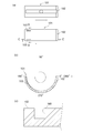
- the front view which shows the slide bearing which concerns on embodiment of this invention (A) The top view which shows the half member which comprises the slide bearing which concerns on embodiment of this invention. (B) A sectional view taken along the line AA. (C) Similarly, a cross-sectional view along the line BB. (A) The three-dimensional graph figure (calculated value) which shows the gradient of the oil film pressure of the slide bearing which provided the narrow groove which concerns on embodiment of this invention. (B) A three-dimensional graph (calculated value) showing the gradient of the oil film pressure of a slide bearing without a narrow groove. (C) The three-dimensional graph figure (calculated value) which shows the gradient of the oil film pressure of the slide bearing which provided the thin groove
- FIG. 1 is a front view of the sliding bearing 1, where the top and bottom of the screen is the vertical direction, and the front and back directions of the screen are the axial directions (front and back directions).
- the slide bearing 1 is a cylindrical member and is applied to a slide bearing structure of an engine crankshaft 11 as shown in FIG.
- the plain bearing 1 is composed of two halved members 2 and 2.
- the two halved members 2 and 2 have a shape obtained by dividing a cylinder into two in parallel to the axial direction, and are formed so that the cross section is a semicircular shape.
- the half members 2 and 2 are arranged up and down, and mating surfaces are arranged on the left and right.
- FIG. 2A shows the upper and lower half members 2.
- the rotation direction of the crankshaft 11 is the clockwise direction when viewed from the front as indicated by the arrow in FIG.
- the bearing angle ⁇ is 0 degree at the right end position in FIG. 2B, and the counterclockwise direction in FIG. 2B is positive. That is, in FIG. 2B, the bearing angle ⁇ at the left end position is defined as 180 degrees, and the bearing angle ⁇ at the lower end position is defined as 270 degrees.
- a groove is provided in the circumferential direction, and a circular hole is provided in the center.
- mating surfaces are arranged on the left and right of the upper half member 2.
- a narrow groove 3 is formed at the axial end of the inner sliding surface of the lower half member 2.
- the narrow groove 3 is provided in the lower half member 2.
- two narrow grooves 3 are provided in parallel in the axial direction.
- the downstream end portion in the rotation direction of the narrow groove 3 is close to the downstream alignment surface in the rotation direction of the crankshaft 11, and the downstream end portion in the rotation direction and the downstream alignment surface in the rotation direction are provided without communication. Yes.
- the end portion on the downstream side in the rotation direction of the narrow groove 3 is disposed at a bearing angle ⁇ 0 that is greater than 180 degrees where the downstream-side mating surface of the crankshaft 11 is located.
- the narrow groove 3 is circular in a direction (counterclockwise direction) in which the bearing angle ⁇ is positive from the bearing angle ⁇ that is larger than the mating surface on the downstream side in the rotation direction of the crankshaft 11 (bearing angle ⁇ is 180 degrees). It is provided in the circumferential direction.
- the right mating surface in FIG. 2B is the upstream mating surface in the rotational direction
- the left mating surface in FIG. 2B is the downstream mating surface in the rotational direction.
- the length 1 of the narrow groove 3 is a length from the downstream end in the rotational direction (bearing angle ⁇ 0) to the upstream end in the rotational direction (bearing angle ⁇ 1).
- the bearing angle ⁇ 1 is greater than ⁇ 0 and equal to or less than 270 degrees. More specifically, the bearing angle ⁇ 1 is present in a region that is usually greater than 225 degrees and less than or equal to 270 degrees.
- the narrow groove 3 is formed so as to have a depth d shallower than the bearing thickness D, as shown in FIG.
- the narrow groove 3 is formed to have a width of w.
- the narrow groove 3 is provided by cutting the inner surface of the half member 2. At this time, no burr is generated because the downstream end portion in the rotational direction and the downstream mating surface do not communicate with each other. That is, when the narrow groove 3 is provided so that the downstream end portion in the rotation direction and the downstream mating surface communicate with each other, burrs generated in the vicinity of the downstream end portion in the rotation direction of the narrow groove 3 are generated. Deburring may be necessary, but deburring is not necessary because the downstream end in the rotation direction and the downstream mating surface do not communicate with each other.
- the gradient of the oil film pressure of the slide bearing 1 provided with the narrow groove 3 will be described with reference to FIG.
- the pressure gradient at the axial end of the half member 2 can be changed as shown in FIG. That is, compared with the case where there is no narrow groove 3 shown in FIG. 3B, the amount of oil sucked back increases as the pressure gradient descending from the bearing end toward the center in the narrow groove 3 increases. The total amount of oil spilled is suppressed.
- the plain bearing 101 used as the comparison object of this embodiment is shown in FIG.
- the plain bearing 101 to be compared is composed of two halved members 102 and 102.
- the upper half member 102 has the same configuration as that of the half member 2 according to the present embodiment, and a description thereof will be omitted.
- a narrow groove 103 is formed at an end portion in the axial direction on the sliding surface on the inner periphery of the lower half member 102.
- FIG. As shown in FIG. As shown in FIG.
- FIG. 3C shows the gradient of the oil film pressure of the sliding bearing 101 that is the comparison target configured as described above.
- the sliding bearing 1 Comparing FIG. 3A and FIG. 3C, the sliding bearing 1 according to the present embodiment has an oil film near the downstream mating surface as compared with the gradient of the oil film pressure of the sliding bearing 101 to be compared. Pressure is high.
- the axial end of the lower half member 2 is arranged in the circumferential direction.
- the narrow groove 3 is provided with a downstream end in the rotational direction of the narrow groove 3 close to the downstream mating surface in the rotational direction, and the downstream end in the rotational direction and the downstream downstream mating surface do not communicate with each other.
- the upstream end of the narrow groove 3 in the rotational direction is upstream of the downstream end of the rotational direction, and is rotated at an angle of 90 ° or less from the downstream mating surface in the rotational direction to the upstream in the rotational direction. It is set at the position.
- the bearing angle ⁇ at the rotation direction downstream mating surface is 180 °
- the bearing angle ⁇ 1 at the upstream end in the rotation direction is configured to satisfy 180 ° ⁇ 0 ⁇ 1 ⁇ 270 °.
- the present invention can be used for a slide bearing technology, and can be used for a slide bearing in which a half member in which a cylinder is divided into two in parallel with an axial direction is arranged vertically.
Abstract
フリクション低減効果を得ることができ、総和の流出油量を抑えることができるすべり軸受を提供することを課題とし、円筒を軸方向と平行に二分割した半割部材2・2を上下に配置したすべり軸受1であって前記下側の半割部材2の軸方向端部に、円周方向に細溝3を設け、細溝3の回転方向下流側端部は、回転方向下流側合わせ面に近接しており、前記回転方向下流側端部と回転方向下流側合わせ面とは連通しない位置に設定し、細溝3の回転方向上流側端部は、回転方向下流側端部よりも上流側であって、回転方向下流側合わせ面から回転方向上流側へ90度以下の角度で回転させた位置に設定したものである。
Description
本発明は、すべり軸受の技術に関し、円筒を軸方向と平行に二分割した半割部材を上下に配置したすべり軸受の技術に関する。
従来、エンジンのクランクシャフトを軸支するための軸受であって、円筒形状を二分割した二つの部材を合わせる半割れ構造のすべり軸受が公知となっている。また、前記軸受の摺動面積を減らし、フリクション低減効果を得るために、前記軸受の幅を狭くする構造がある。しかし、軸受の幅を狭くすると、流出油量が増加していた。そこで、前記軸受の軸方向両端部に、全周に逃げ部分(細溝)を形成した軸受が公知となっている(例えば、特許文献1参照)。
しかし、従来の全周に細溝を形成した軸受では、摺動面積減少により、負荷容量が低下し、良好な潤滑に必要な油膜厚さを確保することができず、且つ、総和の流出油量が多かった。
そこで、本発明は係る課題に鑑み、フリクション低減効果を得ることができ、総和の流出油量を抑えることができる軸受を提供する。
本発明の解決しようとする課題は以上の如くであり、次にこの課題を解決するための手段を説明する。
即ち、請求項1においては、円筒を軸方向と平行に二分割した半割部材を上下に配置したすべり軸受であって前記下側の半割部材の軸方向端部に、円周方向に細溝を設け、
前記細溝の回転方向下流側端部は、回転方向下流側合わせ面に近接しており、前記回転方向下流側端部と回転方向下流側合わせ面とは連通しない位置に設定し、
前記細溝の回転方向上流側端部は、回転方向下流側端部よりも上流側であって、回転方向下流側合わせ面から回転方向上流側へ90度以下の角度で回転させた位置に設定したものである。
前記細溝の回転方向下流側端部は、回転方向下流側合わせ面に近接しており、前記回転方向下流側端部と回転方向下流側合わせ面とは連通しない位置に設定し、
前記細溝の回転方向上流側端部は、回転方向下流側端部よりも上流側であって、回転方向下流側合わせ面から回転方向上流側へ90度以下の角度で回転させた位置に設定したものである。
請求項2においては、前記細溝の回転方向上流側端部は、回転方向下流側合わせ面から回転方向上流側へ45度以上の角度で回転させた位置に設定したものである。
本発明の効果として、以下に示すような効果を奏する。
すなわち、油膜圧力の発生を妨げない程度の細溝を設けることで、摺動面積を減らしつつ、フリクション低減効果を得ることができ、かつ、総和の流出油量を抑えることができる。
また、細溝の回転方向下流側端部と合わせ面とが連通していないため、細溝加工時にバリが発生せず、加工が容易となる。また、細溝の回転方向下流側端部と合わせ面とが連通していないため、合わせ面付近の油膜圧力の低下が軽減されるため、下側の半割部材の上流側合わせ面と下流側合わせ面とを逆に組み付けた場合であっても最低限の油膜圧力を保持することができる。
また、細溝の回転方向下流側端部と合わせ面とが連通していないため、細溝加工時にバリが発生せず、加工が容易となる。また、細溝の回転方向下流側端部と合わせ面とが連通していないため、合わせ面付近の油膜圧力の低下が軽減されるため、下側の半割部材の上流側合わせ面と下流側合わせ面とを逆に組み付けた場合であっても最低限の油膜圧力を保持することができる。
次に、発明の実施の形態を説明する。なお、図1はすべり軸受1の正面図であり、画面の上下を上下方向、画面の手前方向及び奥方向を軸方向(前後方向)とする。
まず、第一の実施形態に係るすべり軸受1を構成する半割部材2について図1及び図2を用いて説明する。
すべり軸受1は円筒状の部材であり、図1に示すように、エンジンのクランクシャフト11のすべり軸受構造に適用される。すべり軸受1は、二つの半割部材2・2で構成されている。二つの半割部材2・2は、円筒を軸方向と平行に二分割した形状であり、断面が半円状となるように形成されている。本実施形態においては、半割部材2・2は上下に配置されており、左右に合わせ面が配置されている。クランクシャフト11をすべり軸受1で軸支する場合、所定の隙間が形成され、この隙間に対し図示せぬ油路から潤滑油が供給される。
すべり軸受1は円筒状の部材であり、図1に示すように、エンジンのクランクシャフト11のすべり軸受構造に適用される。すべり軸受1は、二つの半割部材2・2で構成されている。二つの半割部材2・2は、円筒を軸方向と平行に二分割した形状であり、断面が半円状となるように形成されている。本実施形態においては、半割部材2・2は上下に配置されており、左右に合わせ面が配置されている。クランクシャフト11をすべり軸受1で軸支する場合、所定の隙間が形成され、この隙間に対し図示せぬ油路から潤滑油が供給される。
図2(a)においては、上側および下側の半割部材2を示している。なお、本実施形態においては、クランクシャフト11の回転方向を図1の矢印に示すように正面視時計回り方向とする。また、軸受角度ωは、図2(b)における右端の位置を0度とし、図2(b)において、反時計回り方向を正とする。すなわち、図2(b)において、左端の位置の軸受角度ωが180度となり、下端の位置の軸受角度ωが270度となるように定義する。
上側の半割部材2の内周には円周方向に溝が設けられており、中心に円形の孔が設けられている。また、上側の半割部材2の左右に合わせ面が配置されている。
下側の半割部材2の内周の摺動面において、その軸方向の端部に細溝3が形成されている。
下側の半割部材2の内周の摺動面において、その軸方向の端部に細溝3が形成されている。
細溝3は下側の半割部材2に設けられる。本実施形態においては、細溝3は軸方向に並列して二本設けられている。細溝3の回転方向下流側端部は、クランクシャフト11の回転方向下流側合わせ面に近接しており、回転方向下流側端部と回転方向下流側合わせ面とは連通することなく設けられている。
詳細には、細溝3の回転方向下流側端部が、クランクシャフト11の回転方向下流側合わせ面がある180度よりも大きい軸受角度ω0に配置されている。すなわち、細溝3は、クランクシャフト11の回転方向下流側合わせ面(軸受角度ωが180度)よりも大きい軸受角度ωから軸受角度ωが正となる方向(反時計回り方向)に向けて円周方向に設けられる。
下側の半割部材2においては、図2(b)の右側の合わせ面が回転方向上流側合わせ面、図2(b)の左側の合わせ面が回転方向下流側合わせ面となる。
詳細には、細溝3の回転方向下流側端部が、クランクシャフト11の回転方向下流側合わせ面がある180度よりも大きい軸受角度ω0に配置されている。すなわち、細溝3は、クランクシャフト11の回転方向下流側合わせ面(軸受角度ωが180度)よりも大きい軸受角度ωから軸受角度ωが正となる方向(反時計回り方向)に向けて円周方向に設けられる。
下側の半割部材2においては、図2(b)の右側の合わせ面が回転方向上流側合わせ面、図2(b)の左側の合わせ面が回転方向下流側合わせ面となる。
細溝3の長さlは、回転方向下流側端部(軸受角度がω0)から回転方向上流側端部(軸受角度がω1)までの長さに形成したものである。なお、軸受角度ω1は、ω0よりも大きく270度以下である。より詳細には、軸受角度ω1は、通常225度よりも大きく270度以下である領域に存在する。
細溝3は、図2(c)に示すように、軸受厚さDよりも浅い深さdとなるように形成されている。また、細溝3の幅はwとなるように形成されている。
細溝3は、半割部材2の内側面に切削加工を施すことにより設けられる。この際、回転方向下流側端部と下流側合わせ面とが連通しないことにより、バリが発生しない。すなわち、回転方向下流側端部と下流側合わせ面とが連通するように細溝3を設けた場合には、細溝3の回転方向下流側端部付近に切削加工の際に発生するバリが固着することがあり、バリ取り加工が必要となるが、回転方向下流側端部と下流側合わせ面とが連通しないことにより、バリが発生しないため、バリ取り加工を省くことが可能となる。
次に、細溝3を設けたすべり軸受1の油膜圧力の勾配について図3を用いて説明する。
半割部材2の軸方向端部に細溝3を設けたことにより、図3(a)に示すように、半割部材2の軸方向端部における圧力勾配を変化させることができる。すなわち、図3(b)に示す細溝3がない場合と比べて、細溝3において軸受端部から中央部へ向かって下降する圧力勾配の増加に伴って、油の吸い戻し量が増加し、総和の流出油量が抑制される。
半割部材2の軸方向端部に細溝3を設けたことにより、図3(a)に示すように、半割部材2の軸方向端部における圧力勾配を変化させることができる。すなわち、図3(b)に示す細溝3がない場合と比べて、細溝3において軸受端部から中央部へ向かって下降する圧力勾配の増加に伴って、油の吸い戻し量が増加し、総和の流出油量が抑制される。
また、本実施形態の比較対象となるすべり軸受101を図4に示す。
図4の(a)から(c)に示すように、比較対象となるすべり軸受101は、二つの半割部材102・102で構成されている。ここで、上側の半割部材102は本実施形態に係る半割部材2と同様の構成であるので説明を省略する。
図4(a)および図4(b)に示すように、下側の半割部材102の内周の摺動面において、その軸方向の端部に細溝103が形成されている。
細溝103の回転方向下流側端部は、図4(b)に示すように、クランクシャフト11の回転方向下流側合わせ面と連通するように設けられている。
このように構成した比較対象となるすべり軸受101の油膜圧力の勾配を図3(c)に示す。
図4の(a)から(c)に示すように、比較対象となるすべり軸受101は、二つの半割部材102・102で構成されている。ここで、上側の半割部材102は本実施形態に係る半割部材2と同様の構成であるので説明を省略する。
図4(a)および図4(b)に示すように、下側の半割部材102の内周の摺動面において、その軸方向の端部に細溝103が形成されている。
細溝103の回転方向下流側端部は、図4(b)に示すように、クランクシャフト11の回転方向下流側合わせ面と連通するように設けられている。
このように構成した比較対象となるすべり軸受101の油膜圧力の勾配を図3(c)に示す。
図3(a)及び図3(c)を比較すると、比較対象となるすべり軸受101の油膜圧力の勾配と比べて、本実施形態に係るすべり軸受1の方が、下流側合わせ面付近の油膜圧力が高くなっている。
このため、図5に示すように、上側の半割部材2に対して、下側の半割部材2の上流側及び下流側の合わせ面を逆に組み付けた場合であっても、油膜圧力を最低限保持することができ、すべり軸受1の良好な潤滑に必要な油膜厚さを保持することができる。
以上のように、円筒を軸方向と平行に二分割した半割部材2・2を上下に配置したすべり軸受1であって前記下側の半割部材2の軸方向端部に、円周方向に細溝3を設け、細溝3の回転方向下流側端部は、回転方向下流側合わせ面に近接しており、前記回転方向下流側端部と回転方向下流側合わせ面とは連通しない位置に設定し、細溝3の回転方向上流側端部は、回転方向下流側端部よりも上流側であって、回転方向下流側合わせ面から回転方向上流側へ90度以下の角度で回転させた位置に設定したものである。
ここで、回転方向下流側合わせ面における軸受角度ωが180°であるから、回転方向上流側端部の軸受角度ω1は、180°<ω0<ω1≦270°となるように構成されている。
このように構成することにより、油膜圧力の発生を妨げない程度の細溝を設けることで、摺動面積を減らしつつ、フリクション低減効果を得ることができ、かつ、総和の流出油量を抑えることができる。
また、細溝3の回転方向下流側端部と合わせ面とが連通していないため、細溝3加工時にバリが発生せず、加工が容易となる。また、細溝3の回転方向下流側端部と合わせ面とが連通していないため、合わせ面付近の油膜圧力の低下が軽減されるため、下側の半割部材2の上流側合わせ面と下流側合わせ面とを逆に組み付けた場合であっても最低限の油膜圧力を保持することができる。
本発明は、すべり軸受の技術に利用可能であり、円筒を軸方向と平行に二分割した半割部材を上下に配置したすべり軸受に利用可能である。
1 すべり軸受
2 半割部材
3 細溝
11 クランクシャフト
2 半割部材
3 細溝
11 クランクシャフト
Claims (2)
- 円筒を軸方向と平行に二分割した半割部材を上下に配置したすべり軸受であって前記下側の半割部材の軸方向端部に、円周方向に細溝を設け、
前記細溝の回転方向下流側端部は、回転方向下流側合わせ面に近接しており、前記回転方向下流側端部と回転方向下流側合わせ面とは連通しない位置に設定し、
前記細溝の回転方向上流側端部は、回転方向下流側端部よりも上流側であって、回転方向下流側合わせ面から回転方向上流側へ90度以下の角度で回転させた位置に設定した、
ことを特徴とするすべり軸受。 - 前記細溝の回転方向上流側端部は、回転方向下流側合わせ面から回転方向上流側へ45度以上の角度で回転させた位置に設定した、
ことを特徴とする請求項1に記載のすべり軸受。
Priority Applications (3)
| Application Number | Priority Date | Filing Date | Title |
|---|---|---|---|
| EP14770891.1A EP2977625B1 (en) | 2013-03-21 | 2014-03-19 | Slide bearing |
| US14/778,419 US9657769B2 (en) | 2013-03-21 | 2014-03-19 | Slide bearing |
| CN201480014937.2A CN105074237B (zh) | 2013-03-21 | 2014-03-19 | 滑动轴承 |
Applications Claiming Priority (2)
| Application Number | Priority Date | Filing Date | Title |
|---|---|---|---|
| JP2013058660A JP5837896B2 (ja) | 2013-03-21 | 2013-03-21 | すべり軸受 |
| JP2013-058660 | 2013-03-21 |
Publications (1)
| Publication Number | Publication Date |
|---|---|
| WO2014148573A1 true WO2014148573A1 (ja) | 2014-09-25 |
Family
ID=51580245
Family Applications (1)
| Application Number | Title | Priority Date | Filing Date |
|---|---|---|---|
| PCT/JP2014/057594 WO2014148573A1 (ja) | 2013-03-21 | 2014-03-19 | すべり軸受 |
Country Status (5)
| Country | Link |
|---|---|
| US (1) | US9657769B2 (ja) |
| EP (1) | EP2977625B1 (ja) |
| JP (1) | JP5837896B2 (ja) |
| CN (1) | CN105074237B (ja) |
| WO (1) | WO2014148573A1 (ja) |
Families Citing this family (8)
| Publication number | Priority date | Publication date | Assignee | Title |
|---|---|---|---|---|
| JP6025655B2 (ja) * | 2013-05-16 | 2016-11-16 | 大豊工業株式会社 | すべり軸受の製造方法 |
| JP6266986B2 (ja) * | 2014-01-15 | 2018-01-24 | 大豊工業株式会社 | すべり軸受 |
| JP2016161016A (ja) * | 2015-02-27 | 2016-09-05 | 大豊工業株式会社 | すべり軸受の製造方法及びすべり軸受 |
| JP6314103B2 (ja) * | 2015-02-27 | 2018-04-18 | 大豊工業株式会社 | すべり軸受 |
| JP6181685B2 (ja) | 2015-02-27 | 2017-08-16 | 大豊工業株式会社 | すべり軸受の製造方法及びすべり軸受 |
| JP6893770B2 (ja) * | 2016-10-31 | 2021-06-23 | 大豊工業株式会社 | 半割軸受 |
| JP6777502B2 (ja) * | 2016-10-31 | 2020-10-28 | 大豊工業株式会社 | 半割軸受 |
| JP6773542B2 (ja) * | 2016-12-09 | 2020-10-21 | 大豊工業株式会社 | 半割軸受 |
Citations (5)
| Publication number | Priority date | Publication date | Assignee | Title |
|---|---|---|---|---|
| JPH0348017A (ja) * | 1989-07-12 | 1991-03-01 | Ndc Co Ltd | すべり軸受 |
| JPH06346913A (ja) * | 1993-06-04 | 1994-12-20 | Nissan Motor Co Ltd | エンジンのクランク潤滑装置 |
| JPH08121459A (ja) * | 1994-10-27 | 1996-05-14 | Yanmar Diesel Engine Co Ltd | ディーゼル機関の軸受構造 |
| JP2003532036A (ja) | 2000-05-03 | 2003-10-28 | デーナ、コーポレイション | 軸 受 |
| JP2011089563A (ja) * | 2009-10-21 | 2011-05-06 | Toyota Motor Corp | すべり軸受 |
Family Cites Families (17)
| Publication number | Priority date | Publication date | Assignee | Title |
|---|---|---|---|---|
| US1121904A (en) * | 1912-06-12 | 1914-12-22 | Doehler Die Casting Co | Bearing. |
| US1940301A (en) * | 1931-10-23 | 1933-12-19 | Gen Electric | Shaft bearing |
| DE1450034A1 (de) * | 1964-05-02 | 1969-09-04 | Schmidt Gmbh Karl | Gleitlager mit Schmiermittelnuten |
| DE1525266A1 (de) * | 1965-03-25 | 1969-09-18 | Schmidt Gmbh Karl | Schmutzabweisende OElzufuehrungskanaele in Gleitlagern und Lagerzapfen |
| JPS52113445A (en) * | 1976-03-19 | 1977-09-22 | Daido Metal Co Ltd | Bearing metal |
| US4856366A (en) * | 1986-05-27 | 1989-08-15 | Vilter Manufacturing Company | Connecting rod bearing assembly |
| JPH10231841A (ja) * | 1997-02-21 | 1998-09-02 | Daido Metal Co Ltd | すべり軸受 |
| US6241394B1 (en) * | 2000-01-28 | 2001-06-05 | Hurnischfeger Technologies, Inc. | Lubricating groove pattern for a journal bearing |
| JP2005256917A (ja) * | 2004-03-11 | 2005-09-22 | Daido Metal Co Ltd | すべり軸受 |
| JP5084346B2 (ja) * | 2007-05-17 | 2012-11-28 | 日立造船株式会社 | 軸受メタル |
| JP5096992B2 (ja) * | 2008-04-14 | 2012-12-12 | 大同メタル工業株式会社 | 内燃機関用すべり軸受 |
| JP4951045B2 (ja) * | 2009-09-10 | 2012-06-13 | 大同メタル工業株式会社 | 内燃機関のすべり軸受 |
| DE102010040156A1 (de) * | 2010-09-02 | 2012-03-08 | Federal-Mogul Wiesbaden Gmbh | Schmutzleitnuten in geschmierten Gleitlagern |
| DE102011005467B4 (de) * | 2011-03-11 | 2016-04-28 | Federal-Mogul Wiesbaden Gmbh | Gleitlagerschale mit einer Sammelnut |
| US8608385B2 (en) * | 2011-05-18 | 2013-12-17 | Federal-Mogul Corporation | Main bearing for engine with high belt load |
| JP5895638B2 (ja) | 2012-03-21 | 2016-03-30 | 大豊工業株式会社 | すべり軸受 |
| JP2014119080A (ja) * | 2012-12-19 | 2014-06-30 | Hitachi Ltd | すべり軸受装置 |
-
2013
- 2013-03-21 JP JP2013058660A patent/JP5837896B2/ja active Active
-
2014
- 2014-03-19 WO PCT/JP2014/057594 patent/WO2014148573A1/ja active Application Filing
- 2014-03-19 US US14/778,419 patent/US9657769B2/en active Active
- 2014-03-19 EP EP14770891.1A patent/EP2977625B1/en active Active
- 2014-03-19 CN CN201480014937.2A patent/CN105074237B/zh active Active
Patent Citations (5)
| Publication number | Priority date | Publication date | Assignee | Title |
|---|---|---|---|---|
| JPH0348017A (ja) * | 1989-07-12 | 1991-03-01 | Ndc Co Ltd | すべり軸受 |
| JPH06346913A (ja) * | 1993-06-04 | 1994-12-20 | Nissan Motor Co Ltd | エンジンのクランク潤滑装置 |
| JPH08121459A (ja) * | 1994-10-27 | 1996-05-14 | Yanmar Diesel Engine Co Ltd | ディーゼル機関の軸受構造 |
| JP2003532036A (ja) | 2000-05-03 | 2003-10-28 | デーナ、コーポレイション | 軸 受 |
| JP2011089563A (ja) * | 2009-10-21 | 2011-05-06 | Toyota Motor Corp | すべり軸受 |
Also Published As
| Publication number | Publication date |
|---|---|
| CN105074237B (zh) | 2018-01-16 |
| US20160195127A1 (en) | 2016-07-07 |
| EP2977625A4 (en) | 2016-03-16 |
| JP2014181811A (ja) | 2014-09-29 |
| US9657769B2 (en) | 2017-05-23 |
| EP2977625A1 (en) | 2016-01-27 |
| EP2977625B1 (en) | 2019-10-09 |
| CN105074237A (zh) | 2015-11-18 |
| JP5837896B2 (ja) | 2015-12-24 |
Similar Documents
| Publication | Publication Date | Title |
|---|---|---|
| WO2014148573A1 (ja) | すべり軸受 | |
| JP6096689B2 (ja) | すべり軸受 | |
| JP6185853B2 (ja) | すべり軸受 | |
| WO2015072407A1 (ja) | すべり軸受 | |
| JP6266986B2 (ja) | すべり軸受 | |
| WO2014129595A1 (ja) | すべり軸受 | |
| JP2018080821A (ja) | すべり軸受 | |
| JP6216226B2 (ja) | すべり軸受 | |
| JP2016161016A (ja) | すべり軸受の製造方法及びすべり軸受 | |
| JP6536774B2 (ja) | すべり軸受 | |
| WO2016136995A1 (ja) | すべり軸受 | |
| JP6323833B2 (ja) | すべり軸受 | |
| WO2017104795A1 (ja) | すべり軸受 | |
| JP6166064B2 (ja) | すべり軸受 | |
| WO2016136993A1 (ja) | すべり軸受 | |
| JP6724280B2 (ja) | すべり軸受 | |
| JP6624559B2 (ja) | すべり軸受 | |
| JP6399576B2 (ja) | すべり軸受 | |
| JP6541144B2 (ja) | すべり軸受 | |
| JP2017110765A (ja) | すべり軸受 | |
| JP2017110764A (ja) | すべり軸受 |
Legal Events
| Date | Code | Title | Description |
|---|---|---|---|
| WWE | Wipo information: entry into national phase |
Ref document number: 201480014937.2 Country of ref document: CN |
|
| 121 | Ep: the epo has been informed by wipo that ep was designated in this application |
Ref document number: 14770891 Country of ref document: EP Kind code of ref document: A1 |
|
| DPE1 | Request for preliminary examination filed after expiration of 19th month from priority date (pct application filed from 20040101) | ||
| WWE | Wipo information: entry into national phase |
Ref document number: 14778419 Country of ref document: US |
|
| NENP | Non-entry into the national phase |
Ref country code: DE |
|
| WWE | Wipo information: entry into national phase |
Ref document number: 2014770891 Country of ref document: EP |