WO2014141869A1 - 操作ケーブルの配索構造 - Google Patents
操作ケーブルの配索構造 Download PDFInfo
- Publication number
- WO2014141869A1 WO2014141869A1 PCT/JP2014/054481 JP2014054481W WO2014141869A1 WO 2014141869 A1 WO2014141869 A1 WO 2014141869A1 JP 2014054481 W JP2014054481 W JP 2014054481W WO 2014141869 A1 WO2014141869 A1 WO 2014141869A1
- Authority
- WO
- WIPO (PCT)
- Prior art keywords
- operation cable
- handle
- cable
- door lock
- handle device
- Prior art date
Links
Images


Classifications
-
- B—PERFORMING OPERATIONS; TRANSPORTING
- B60—VEHICLES IN GENERAL
- B60J—WINDOWS, WINDSCREENS, NON-FIXED ROOFS, DOORS, OR SIMILAR DEVICES FOR VEHICLES; REMOVABLE EXTERNAL PROTECTIVE COVERINGS SPECIALLY ADAPTED FOR VEHICLES
- B60J5/00—Doors
- B60J5/04—Doors arranged at the vehicle sides
- B60J5/0468—Fixation or mounting means specific for door components
-
- E—FIXED CONSTRUCTIONS
- E05—LOCKS; KEYS; WINDOW OR DOOR FITTINGS; SAFES
- E05B—LOCKS; ACCESSORIES THEREFOR; HANDCUFFS
- E05B61/00—Other locks with provision for latching
-
- E—FIXED CONSTRUCTIONS
- E05—LOCKS; KEYS; WINDOW OR DOOR FITTINGS; SAFES
- E05B—LOCKS; ACCESSORIES THEREFOR; HANDCUFFS
- E05B77/00—Vehicle locks characterised by special functions or purposes
- E05B77/02—Vehicle locks characterised by special functions or purposes for accident situations
- E05B77/04—Preventing unwanted lock actuation, e.g. unlatching, at the moment of collision
- E05B77/06—Preventing unwanted lock actuation, e.g. unlatching, at the moment of collision by means of inertial forces
-
- E—FIXED CONSTRUCTIONS
- E05—LOCKS; KEYS; WINDOW OR DOOR FITTINGS; SAFES
- E05B—LOCKS; ACCESSORIES THEREFOR; HANDCUFFS
- E05B77/00—Vehicle locks characterised by special functions or purposes
- E05B77/36—Noise prevention; Anti-rattling means
-
- E—FIXED CONSTRUCTIONS
- E05—LOCKS; KEYS; WINDOW OR DOOR FITTINGS; SAFES
- E05B—LOCKS; ACCESSORIES THEREFOR; HANDCUFFS
- E05B79/00—Mounting or connecting vehicle locks or parts thereof
- E05B79/10—Connections between movable lock parts
- E05B79/20—Connections between movable lock parts using flexible connections, e.g. Bowden cables
-
- E—FIXED CONSTRUCTIONS
- E05—LOCKS; KEYS; WINDOW OR DOOR FITTINGS; SAFES
- E05B—LOCKS; ACCESSORIES THEREFOR; HANDCUFFS
- E05B79/00—Mounting or connecting vehicle locks or parts thereof
- E05B79/10—Connections between movable lock parts
- E05B79/22—Operative connections between handles, sill buttons or lock knobs and the lock unit
-
- E—FIXED CONSTRUCTIONS
- E05—LOCKS; KEYS; WINDOW OR DOOR FITTINGS; SAFES
- E05B—LOCKS; ACCESSORIES THEREFOR; HANDCUFFS
- E05B85/00—Details of vehicle locks not provided for in groups E05B77/00 - E05B83/00
- E05B85/10—Handles
- E05B85/14—Handles pivoted about an axis parallel to the wing
- E05B85/16—Handles pivoted about an axis parallel to the wing a longitudinal grip part being pivoted at one end about an axis perpendicular to the longitudinal axis of the grip part
-
- E—FIXED CONSTRUCTIONS
- E05—LOCKS; KEYS; WINDOW OR DOOR FITTINGS; SAFES
- E05C—BOLTS OR FASTENING DEVICES FOR WINGS, SPECIALLY FOR DOORS OR WINDOWS
- E05C3/00—Fastening devices with bolts moving pivotally or rotatively
- E05C3/12—Fastening devices with bolts moving pivotally or rotatively with latching action
- E05C3/16—Fastening devices with bolts moving pivotally or rotatively with latching action with operating handle or equivalent member moving otherwise than rigidly with the latch
- E05C3/162—Fastening devices with bolts moving pivotally or rotatively with latching action with operating handle or equivalent member moving otherwise than rigidly with the latch the handle or member moving essentially towards or away of the plane of the wing or frame
-
- E—FIXED CONSTRUCTIONS
- E05—LOCKS; KEYS; WINDOW OR DOOR FITTINGS; SAFES
- E05F—DEVICES FOR MOVING WINGS INTO OPEN OR CLOSED POSITION; CHECKS FOR WINGS; WING FITTINGS NOT OTHERWISE PROVIDED FOR, CONCERNED WITH THE FUNCTIONING OF THE WING
- E05F7/00—Accessories for wings not provided for in other groups of this subclass
-
- E—FIXED CONSTRUCTIONS
- E05—LOCKS; KEYS; WINDOW OR DOOR FITTINGS; SAFES
- E05C—BOLTS OR FASTENING DEVICES FOR WINGS, SPECIALLY FOR DOORS OR WINDOWS
- E05C1/00—Fastening devices with bolts moving rectilinearly
- E05C1/08—Fastening devices with bolts moving rectilinearly with latching action
- E05C1/12—Fastening devices with bolts moving rectilinearly with latching action with operating handle or equivalent member moving otherwise than rigidly with the latch
- E05C1/14—Fastening devices with bolts moving rectilinearly with latching action with operating handle or equivalent member moving otherwise than rigidly with the latch the handle or member moving essentially towards or away from the plane of the wing or frame
Definitions
- the present invention relates to an operation cable routing structure.
- Patent Document 1 As an arrangement structure of an operation cable for connecting the handle device and the door lock device when the vehicle handle device and the door lock device are arranged close to each other, the one described in Patent Document 1 is known.
- the handle device is formed by rotatably connecting an outside handle (operation handle) to a case (handle base), and the rotational force of the bell crank accompanying the rotation operation of the operation handle is transmitted via an operation cable.
- operation handle operation handle
- case case base
- the output of the bell crank located on the rotation tip side of the operation handle is temporarily transmitted via the link.
- the operation handle is pulled out to the rotation base end side, and one end of the operation cable is connected to a lever connected to the link.
- the present invention has been made to solve the above-described drawbacks, and an object of the present invention is to provide an operation cable routing structure in which the operation cable 7 can be routed with a simple structure and a sufficient extra length. To do.
- Another object of the present invention is to provide a handle device that can be used in the above structure.
- the object is A handle device 5 for outputting an operation force to an operation handle 3 fixed to a vehicle door 1 and rotatably connected to a handle base 2 from an output unit 4;
- a door lock device 6 disposed close to the output unit 4 of the handle device 5;
- An operation cable 7 for connecting the output unit 4 of the handle device 5 and the door lock device 6;
- the operation cable 7 is connected to the door lock device 6 via an extra length securing path that goes around the periphery of the handle device 5 from the output unit 4, and
- the operation cable 7 is supported on the handle base 2 movably by a guide portion 9 provided at an intermediate position between the connection portion of the operation cable 7 with the door lock device 6 and the movable member 8 of the handle device 5. This is achieved by providing an operation cable routing structure in which the movable member 8 is restricted from entering the movable region.
- the operation cable 7 is routed on a surplus length securing path that encloses almost the entire circumference of the handle device 5 along the peripheral edge portion of the handle device 5, and the output cable 4 and the door lock of the handle device 5 are arranged. Even when the device 6 is disposed close to the handle device 5, a sufficient extra length is secured on the periphery of the handle device 5. For this reason, even if a change occurs in the distance between the two due to deformation of the door 1 at the time of the accident, the change amount is absorbed by the extra length of the operation cable 7. As a result, it is possible to reliably prevent inadvertent opening of the door 1 and the like without using a special member.
- the operation cable 7 does not enter the movable region of the movable member 8 that is operated when the operation handle 3 is operated. It becomes possible to prevent the occurrence of malfunction due to the operation handle 3 being bitten inside.
- the guide portion 9 forms the operation cable 7 by supporting the operation cable 7 movably, and the relative position between the handle device 5 and the door lock device 6 is changed so as not to restrain the movement of the operation cable 7. Even in such a case, the operation cable 7 can move relative to the guide portion 9 to supply the extra length, thereby reliably absorbing the dimensional change.
- the guide cable 9 constitutes an operation cable routing structure that supports the operation cable 7 so as to be detachable by movement of the operation cable 7 in the vehicle width direction
- the guide unit 9 is a basic deformation mode at the time of a side collision.
- the operation cable 7 is detached from the guide portion 9 and the restraint on the operation cable 7 is completely released, so that the extra length component can be supplied more reliably. become.
- a cable connecting portion 11 for connecting one end of an operation cable 7 for taking out the displacement of the output portion 4 is provided on the edge portion of the handle base 2 opposite to the shaft supporting side edge portion of the output portion 4, and the output portion 4 is a guide portion that supports an operation cable 7 routed along almost the entire circumference along the periphery of the handle base 2 so as to be movable and restricts entry into the counterweight 8 movable region.
- the handle device 5 provided with 9 can be used.
- the guide portion 9 is formed in a rectangular plate shape, and constitutes a handle device 5 that supports the operation cable 7 at one side edge so as to be detachable with respect to movement of the operation cable 7 in the vehicle width direction.
- a handle device 5 that supports the operation cable 7 at one side edge so as to be detachable with respect to movement of the operation cable 7 in the vehicle width direction.
- the operation cable 7 can be routed with a simple structure and a sufficient extra length.
- FIG. 3A is a cross-sectional view taken along line 3A-3A in FIG. 1
- FIG. 3B is a cross-sectional view taken along line 3B-3B in FIG. It is a figure which shows a handle base, (a) is a rear view, (b) is a principal part expansion perspective view.
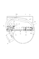
- FIG. 1 shows an embodiment of the present invention in which an outside handle device 5 and a door lock device 6 of a vehicle are connected by an operation cable 7.
- FIG. 1 shows an embodiment of the present invention in which an outside handle device 5 and a door lock device 6 of a vehicle are connected by an operation cable 7.
- the handle device 5 is formed by connecting a grip-type operation handle 3 that is long in the vehicle length direction to the handle base 2, and is formed at an initial rotational position shown in FIG. A rotation operation can be performed between the rotation position around the rotation center 3a and the operation rotation position rotated in the direction of arrow A in FIG.
- an operating leg 3b is formed at the rotating tip of the operation handle 3 so as to project inward of the door 1, and a lever 12 is provided on the handle base 2 so that an operating piece 12a is engaged with the operating leg 3b.
- the counterweight (movable member 8) coupled to the lever 12 is coupled to be rotatable about the rotation shaft 12b.
- the lever 12 can be rotated from an initial rotation position corresponding to the initial rotation position of the operation handle 3 to an operation rotation position corresponding to the operation rotation position, and by the biasing force applied to the counterweight 8 by the torsion spring 13, Be energized by.
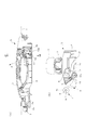
- the counterweight 8 is necessary for canceling the operation force toward the operation rotational position of the lever 12 due to the inertial force in the door 1 opening direction generated in the operation handle 3 when a side collision force is applied to the door 1 of the vehicle. It has a heavy weight and is disposed along one side edge of the handle base 2.
- the handle base 2 is provided with a cable connecting portion 11 as shown in FIGS.
- the cable connecting portion 11 serves as a drawing portion for the operation cable 7 to be described later, and is disposed on the side edge opposite to the side edge of the handle base 2 to which the counterweight 8 is mounted in order to prevent interference with the counterweight 8. .
- the door lock device 6 operated by the handle device 5 includes a latch (not shown) for maintaining the closed posture of the door 1, and as shown in FIG. 2, at a position close to the handle device 5.
- the handle device 5 is fixed to the door 1 and is remotely operated by the handle device 5 by transmitting the operation force to the handle device 5 through the operation cable 7.
- the operation cable 7 is formed by slidably inserting the inner cable 7b into the outer cable 7a, and one end is connected to the handle device 5 and the other end is connected to the door lock device 6.
- the operation cable 7 is covered with a sponge-like tube 10 such as urethane foam at an appropriate position in order to prevent a collision noise with the door panel (door 1) during traveling.
- connection of the operation cable 7 with the handle device 5 is performed by fixing one end of the outer cable to the cable connecting portion 11 and connecting the corresponding end of the inner cable 7b to the connection point 4 of the lever 12.
- the door lock device 6 is disposed in the vicinity of the drawer portion of the operation cable 7 from the handle device 5, and when these are directly connected by the operation cable 7, the cable routing distance is too short.
- the connection end of the inner cable 7b Due to the increase in the interval, the connecting end of the inner cable 7b of the door lock device 6 is pulled, the door lock device 6 operates, and the door 1 may be opened carelessly.
- the operation cable 7 is routed along the extra length securing path as shown in FIGS.
- the extra length routing path is once drawn from the connecting end to the handle device 5 to the opposite end (front end), and then guided to the rear end along the opposite edge with respect to the side edge where the cable connecting portion 11 is disposed.
- This is a route that surrounds almost the entire circumference of the handle device 5 that returns to the arrangement side edge of the cable connecting portion 11 again.
- the position change is absorbed by the operation cable 7 supplied from the routing route, and the operation force to the door lock device 6 is prevented from being generated.
- the operation cable 7 is sandwiched between the front end portion of the handle base 2 and the door 1 panel as shown in FIG. As shown in FIG. 1, the base end corner of the cable retainer 2a functions as a guide.
- the operation cable 7 when the operation cable 7 is routed around the handle device 5, the operation cable 7 may enter the movable range of the counterweight 8, as indicated by a broken line. In this case, when the operation handle 3 is operated, there is a possibility that the operation cable 7 is caught in the counterweight 8 and malfunction occurs.
- the handle base 2 is provided with a guide portion 9.
- the guide portion 9 is formed in a rectangular plate shape at an intermediate portion between the counterweight 8 and the door lock device 6 on the side edge where the counterweight 8 is disposed.
- the operation cable 7 is guided in the vicinity of the counterweight 8 in the direction away from the movable range of the counterweight 8 indicated by a chain line in FIG. 2 by the guide portion 9, so that the engagement with the counterweight 8 is reliably prevented.
- the operation cable 7 since the operation cable 7 is guided while being supported by the guide portion 9, the operation cable 7 can be easily slid with respect to the load in the axial length direction, and can be applied to the load in the vehicle width direction.
- the guide part 9 since the guide part 9 is easily detached from the guide part 9, the guide part 9 does not hinder the supply of the surplus length part to the dimension change part by restraining the movement of the operation cable 7.
- a plate-like guide member 14 is fixed to the door 1 to shape the extra length securing path.
- the guide member 14 pushes the side surface of the operation cable 7 to the handle device 5 side by the guide protrusion 14a, and the curvature in the vicinity of the counterweight 8 is compared with a free state where there is no guide by the guide portion 9 material.
- the operation cable 7 is moved away from the movable range of the counterweight 8 by reducing the distance.
- the guide protrusion 14a of the guide portion 9 material only presses the operation cable 7. Therefore, the movement of the operation cable 7 in the axial length direction or the movement in the vehicle width direction is restricted. do not do.
Abstract
Description
車両のドア1に固定され、ハンドルベース2に回転自在に連結された操作ハンドル3への操作力を出力部4から出力するハンドル装置5と、
ハンドル装置5の出力部4に近接配置されるドアロック装置6と、
ハンドル装置5の出力部4とドアロック装置6とを連結する操作ケーブル7とを有し、
前記操作ケーブル7は、出力部4からハンドル装置5周辺をほぼ一周する余長確保経路を経由してドアロック装置6に連結されるとともに、
前記操作ケーブル7は、ハンドルベース2上であって、操作ケーブル7のドアロック装置6との連結部とハンドル装置5の可動部材8の中間位置に設けられるガイド部9により移動可能に支えられて可動部材8の可動領域内への進入が規制される操作ケーブルの配索構造を提供することにより達成される。
前記ガイド部9は、操作ケーブル7の車幅方向への移動により離脱可能に操作ケーブル7を支承する操作ケーブルの配索構造を構成すると、側方衝突時の基本変形モードであるハンドル装置5とドアロック装置6とが車幅方向に相対移動した際には、操作ケーブル7がガイド部9から離脱して操作ケーブル7に対する拘束が完全に解除されるために、余長成分の供給がより確実になる。
前記操作ケーブル7のガイド部9による被支承部にはスポンジ状チューブ10が装着される操作ケーブルの配索構造を構成した場合、操作ケーブル7はスポンジ状のチューブを介してガイド部9に支えられるために、通常の配索作業時には、チューブが撓んでガイド部9に馴染んで不用意な離脱が発生せず、かつ、ドア1変形等の大きな力が作用した場合には、操作ケーブル7とガイド部9との必要な移動を妨げることがないために、寸法変化解消性能に悪影響を及ぼさない。
車両のドア1に固定されるハンドルベース2と、
ハンドルベース2の一端に回転自在に連結される操作ハンドル3と、
ハンドルベース2の他端一辺部に回転自在に連結され、前記操作ハンドル3の回転先端の変位により回転駆動されるとともに、ドア1への側方衝突による慣性力を打ち消すカウンタウエイト8を備えた出力部4とを有し、
前記ハンドルベース2の出力部4の軸支側辺縁部に対向する辺縁部には、出力部4の変位を取り出す操作ケーブル7の一端を連結するケーブル連結部11が設けられるとともに、出力部4の軸支側辺縁部には、ハンドルベース2の周縁に沿ってほぼ全周にわたって配索される操作ケーブル7を移動自在に支承してカウンタウエイト8可動領域への進入を規制するガイド部9が設けられるハンドル装置5が使用できる。
前記ガイド部9は、矩形プレート形状に形成されて一側端縁において前記操作ケーブル7を該操作ケーブル7の車幅方向への移動に対して脱離可能に支承するハンドル装置5を構成することにより寸法変化吸収能を向上させることが可能になる。
2 ハンドルベース
3 操作ハンドル
4 出力部
5 ハンドル装置
6 ドアロック装置
7 操作ケーブル
8 可動部材
9 ガイド部
10 スポンジ状チューブ
11 ケーブル連結部
Claims (5)
- 車両のドアに固定され、ハンドルベースに回転自在に連結された操作ハンドルへの操作力を出力部から出力するハンドル装置と、
ハンドル装置の出力部に近接配置されるドアロック装置と、
ハンドル装置の出力部とドアロック装置とを連結する操作ケーブルとを有し、
前記操作ケーブルは、出力部からハンドル装置周辺をほぼ一周する余長確保経路を経由してドアロック装置に連結されるとともに、
前記操作ケーブルは、ハンドルベース上であって、操作ケーブルのドアロック装置との連結部とハンドル装置の可動部材の中間位置に設けられるガイド部により移動可能に支えられて可動部材の可動領域内への進入が規制される操作ケーブルの配索構造。 - 前記ガイド部は、操作ケーブルの車幅方向への移動により離脱可能に操作ケーブルを支承する請求項1記載の操作ケーブルの配索構造。
- 前記操作ケーブルのガイド部による被支承部にはスポンジ状チューブが装着される請求項1記載の操作ケーブルの配索構造。
- 車両のドアに固定されるハンドルベースと、
ハンドルベースの一端に回転自在に連結される操作ハンドルと、
ハンドルベースの他端一辺部に回転自在に連結され、前記操作ハンドルの回転先端の変位により回転駆動されるとともに、ドアへの側方衝突による慣性力を打ち消すカウンタウエイトを備えた出力部とを有し、
前記ハンドルベースの出力部の軸支側の辺縁部に対向する辺縁部には、出力部の変位を取り出す操作ケーブルの一端を連結するケーブル連結部が設けられるとともに、出力部の軸支側辺縁部には、ハンドルベースの周縁に沿ってほぼ全周にわたって配索される操作ケーブルを移動自在に支承してカウンタウエイト可動領域への進入を規制するガイド部が設けられるハンドル装置。 - 前記ガイド部は、矩形プレート形状に形成されて一側端縁において前記操作ケーブルを該操作ケーブルの車幅方向への移動に対して脱離可能に支承する請求項4記載のハンドル装置。
Priority Applications (5)
| Application Number | Priority Date | Filing Date | Title |
|---|---|---|---|
| CN201480010400.9A CN105074107B (zh) | 2013-03-12 | 2014-02-25 | 操作线缆的布线结构以及把手装置 |
| US14/766,143 US9333838B2 (en) | 2013-03-12 | 2014-02-25 | Routing structure of operation cable |
| RU2015139517A RU2624192C2 (ru) | 2013-03-12 | 2014-02-25 | Устройство проводки функционального тросика |
| EP14764725.9A EP2933406B1 (en) | 2013-03-12 | 2014-02-25 | Routing structure for operation cable |
| KR1020157027620A KR101798311B1 (ko) | 2013-03-12 | 2014-02-25 | 조작 케이블의 배선 구조 |
Applications Claiming Priority (2)
| Application Number | Priority Date | Filing Date | Title |
|---|---|---|---|
| JP2013-049371 | 2013-03-12 | ||
| JP2013049371A JP6096008B2 (ja) | 2013-03-12 | 2013-03-12 | 操作ケーブルの配索構造 |
Publications (1)
| Publication Number | Publication Date |
|---|---|
| WO2014141869A1 true WO2014141869A1 (ja) | 2014-09-18 |
Family
ID=51536544
Family Applications (1)
| Application Number | Title | Priority Date | Filing Date |
|---|---|---|---|
| PCT/JP2014/054481 WO2014141869A1 (ja) | 2013-03-12 | 2014-02-25 | 操作ケーブルの配索構造 |
Country Status (7)
| Country | Link |
|---|---|
| US (1) | US9333838B2 (ja) |
| EP (1) | EP2933406B1 (ja) |
| JP (1) | JP6096008B2 (ja) |
| KR (1) | KR101798311B1 (ja) |
| CN (1) | CN105074107B (ja) |
| RU (1) | RU2624192C2 (ja) |
| WO (1) | WO2014141869A1 (ja) |
Families Citing this family (11)
| Publication number | Priority date | Publication date | Assignee | Title |
|---|---|---|---|---|
| KR101628499B1 (ko) * | 2014-10-17 | 2016-06-21 | 현대자동차주식회사 | 측면 충돌시 도어 열림이 방지되는 구조 및 그 방법 |
| US10865588B2 (en) | 2015-08-24 | 2020-12-15 | Dan Raz Ltd. | Securing mechanism for a sliding panel |
| US9970214B2 (en) | 2015-11-29 | 2018-05-15 | Dan Raz Ltd | Door or other closable panel with lock-actuating linkage |
| US10487545B2 (en) | 2016-03-03 | 2019-11-26 | Dan Raz Ltd. | Latch arrangement having a stop latch |
| US9988830B2 (en) * | 2016-03-03 | 2018-06-05 | Dan Raz Ltd. | Latch arrangement having a handle |
| DE102016212215A1 (de) * | 2016-07-05 | 2018-01-11 | Volkswagen Aktiengesellschaft | Anordnung zur Verhinderung eines selbsttätigen Öffnens einer Fahrzeugtür oder-klappe sowie Fahrzeug mit einer derartigen Anordnung |
| JP6938132B2 (ja) | 2016-11-07 | 2021-09-22 | 株式会社アルファ | 車両のハンドル装置 |
| JP6963410B2 (ja) * | 2017-05-19 | 2021-11-10 | 株式会社アルファ | 車両のハンドル装置 |
| US11598125B2 (en) | 2017-09-03 | 2023-03-07 | Dan Raz Ltd. | Latch arrangement |
| KR102518541B1 (ko) * | 2017-12-01 | 2023-04-07 | 현대자동차주식회사 | 그립 일체형 인사이드핸들 |
| JP6744881B2 (ja) * | 2018-02-20 | 2020-08-19 | 三井金属アクト株式会社 | 自動車用ドアラッチ装置 |
Citations (6)
| Publication number | Priority date | Publication date | Assignee | Title |
|---|---|---|---|---|
| JPH0443670U (ja) * | 1990-08-20 | 1992-04-14 | ||
| JPH0628144U (ja) * | 1992-09-21 | 1994-04-15 | 株式会社大井製作所 | 自動車用ドアロックと操作装置との連結装置 |
| JP2003148004A (ja) | 2001-11-12 | 2003-05-21 | Oi Seisakusho Co Ltd | 車両用ドアのドアロック装置 |
| JP2007118793A (ja) * | 2005-10-28 | 2007-05-17 | Honda Motor Co Ltd | フードロック解除ケーブルの配索構造 |
| JP2009275371A (ja) * | 2008-05-13 | 2009-11-26 | Mitsui Mining & Smelting Co Ltd | 自動車用ドア |
| JP2012237143A (ja) * | 2011-05-12 | 2012-12-06 | Alpha Corp | 可動部材へのケーブル連結構造 |
Family Cites Families (13)
| Publication number | Priority date | Publication date | Assignee | Title |
|---|---|---|---|---|
| GB2261916A (en) * | 1991-11-30 | 1993-06-02 | Angelo Guerrini | Remotely controlled operation of vehicle doors |
| US5605363A (en) * | 1995-02-07 | 1997-02-25 | Chrysler Corporation | Sliding door latch control assembly |
| ITTO20011000A1 (it) * | 2001-10-19 | 2003-04-19 | Atoma Roltra Spa | Serratura modulare per una portiera di un autoveicolo e portiera provvista di tale serratura. |
| JP4108455B2 (ja) * | 2002-11-25 | 2008-06-25 | 三井金属鉱業株式会社 | ドアラッチ装置 |
| JP2005035453A (ja) * | 2003-07-17 | 2005-02-10 | Nissan Motor Co Ltd | 車両用ドアのドアロック装置 |
| US7448166B2 (en) * | 2005-02-14 | 2008-11-11 | Toyota Motor Engineering & Manufacturing North America, Inc. | Cable guide mechanism for luggage handles |
| US7568744B2 (en) * | 2005-09-22 | 2009-08-04 | Nissan Technical Center North America, Inc. | Vehicle door handle assembly |
| US8069616B2 (en) * | 2007-09-07 | 2011-12-06 | Brose Schliesssysteme Gmbh & Co. Kg | Method for mounting a motor vehicle door lock |
| ITMI20071748A1 (it) * | 2007-09-11 | 2009-03-12 | Valeo Sicurezza Abitacolo Spa | Maniglia di sicurezza per veicoli |
| US8576047B2 (en) * | 2008-03-13 | 2013-11-05 | Huf Hulsbeck & Furst Gmbh & Co. Kg | Motor vehicle outside door handle with a sensor module |
| US8152209B2 (en) * | 2008-03-31 | 2012-04-10 | Illinois Tool Works Inc. | Delay apparatus for opening of vehicle door |
| IT1397430B1 (it) | 2009-12-11 | 2013-01-10 | Illinois Tool Works | Gruppo maniglia per una porta di veicolo. |
| CN102654004B (zh) * | 2011-03-02 | 2014-12-17 | 布罗斯锁闭系统有限责任两合公司 | 机动车锁 |
-
2013
- 2013-03-12 JP JP2013049371A patent/JP6096008B2/ja active Active
-
2014
- 2014-02-25 CN CN201480010400.9A patent/CN105074107B/zh active Active
- 2014-02-25 KR KR1020157027620A patent/KR101798311B1/ko active IP Right Grant
- 2014-02-25 WO PCT/JP2014/054481 patent/WO2014141869A1/ja active Application Filing
- 2014-02-25 EP EP14764725.9A patent/EP2933406B1/en active Active
- 2014-02-25 RU RU2015139517A patent/RU2624192C2/ru not_active IP Right Cessation
- 2014-02-25 US US14/766,143 patent/US9333838B2/en active Active
Patent Citations (6)
| Publication number | Priority date | Publication date | Assignee | Title |
|---|---|---|---|---|
| JPH0443670U (ja) * | 1990-08-20 | 1992-04-14 | ||
| JPH0628144U (ja) * | 1992-09-21 | 1994-04-15 | 株式会社大井製作所 | 自動車用ドアロックと操作装置との連結装置 |
| JP2003148004A (ja) | 2001-11-12 | 2003-05-21 | Oi Seisakusho Co Ltd | 車両用ドアのドアロック装置 |
| JP2007118793A (ja) * | 2005-10-28 | 2007-05-17 | Honda Motor Co Ltd | フードロック解除ケーブルの配索構造 |
| JP2009275371A (ja) * | 2008-05-13 | 2009-11-26 | Mitsui Mining & Smelting Co Ltd | 自動車用ドア |
| JP2012237143A (ja) * | 2011-05-12 | 2012-12-06 | Alpha Corp | 可動部材へのケーブル連結構造 |
Non-Patent Citations (1)
| Title |
|---|
| See also references of EP2933406A4 |
Also Published As
| Publication number | Publication date |
|---|---|
| JP6096008B2 (ja) | 2017-03-15 |
| US9333838B2 (en) | 2016-05-10 |
| EP2933406B1 (en) | 2017-04-12 |
| CN105074107A (zh) | 2015-11-18 |
| EP2933406A4 (en) | 2016-01-13 |
| RU2015139517A (ru) | 2017-04-17 |
| CN105074107B (zh) | 2018-01-19 |
| RU2624192C2 (ru) | 2017-06-30 |
| KR20150130365A (ko) | 2015-11-23 |
| EP2933406A1 (en) | 2015-10-21 |
| KR101798311B1 (ko) | 2017-11-15 |
| US20160001643A1 (en) | 2016-01-07 |
| JP2014173385A (ja) | 2014-09-22 |
Similar Documents
| Publication | Publication Date | Title |
|---|---|---|
| JP6096008B2 (ja) | 操作ケーブルの配索構造 | |
| KR101932807B1 (ko) | 차량용 핸들 장치 | |
| JP5039015B2 (ja) | 車両のドアハンドル装置 | |
| JP4015635B2 (ja) | 車両用ドアハンドル装置 | |
| KR101827147B1 (ko) | 도어 아웃사이드 핸들 | |
| WO2012153572A1 (ja) | 可動部材へのケーブル連結構造 | |
| JP2007106233A (ja) | アームレスト構造 | |
| WO2016148181A1 (ja) | 車両用ドアハンドル装置 | |
| JP5595133B2 (ja) | 車両のドアハンドル装置 | |
| JP5895796B2 (ja) | 車両用シート | |
| JP2009255635A (ja) | フードロック装置 | |
| JP2009133134A (ja) | 自動車のドアハンドル装置 | |
| JP5235465B2 (ja) | ロック装置 | |
| JP2015040377A (ja) | 車両用ハンドル装置 | |
| JP2008162382A (ja) | スライドドア装置 | |
| JP2013224544A (ja) | 車両用ドア構造 | |
| JP5478932B2 (ja) | パワースライド装置 | |
| KR101596572B1 (ko) | 자동차용 래치장치 | |
| JP6327976B2 (ja) | ドアハンドル装置 | |
| KR100812439B1 (ko) | 측면 충돌시 관성력에 의한 도어아웃사이드핸들의 개방동작구속장치 | |
| JP5544641B2 (ja) | 収容構造体装置 | |
| JP2019006161A (ja) | ドアエッジ保護装置 | |
| WO2015053216A1 (ja) | 給電装置 | |
| JP6549357B2 (ja) | 車両のハンドル装置 | |
| JP2006290230A (ja) | 跳ね上げ式フード構造 |
Legal Events
| Date | Code | Title | Description |
|---|---|---|---|
| WWE | Wipo information: entry into national phase |
Ref document number: 201480010400.9 Country of ref document: CN |
|
| 121 | Ep: the epo has been informed by wipo that ep was designated in this application |
Ref document number: 14764725 Country of ref document: EP Kind code of ref document: A1 |
|
| REEP | Request for entry into the european phase |
Ref document number: 2014764725 Country of ref document: EP |
|
| WWE | Wipo information: entry into national phase |
Ref document number: 2014764725 Country of ref document: EP |
|
| WWE | Wipo information: entry into national phase |
Ref document number: 14766143 Country of ref document: US |
|
| NENP | Non-entry into the national phase |
Ref country code: DE |
|
| ENP | Entry into the national phase |
Ref document number: 20157027620 Country of ref document: KR Kind code of ref document: A |
|
| ENP | Entry into the national phase |
Ref document number: 2015139517 Country of ref document: RU Kind code of ref document: A |