EP2933406B1 - Routing structure for operation cable - Google Patents
Routing structure for operation cable Download PDFInfo
- Publication number
- EP2933406B1 EP2933406B1 EP14764725.9A EP14764725A EP2933406B1 EP 2933406 B1 EP2933406 B1 EP 2933406B1 EP 14764725 A EP14764725 A EP 14764725A EP 2933406 B1 EP2933406 B1 EP 2933406B1
- Authority
- EP
- European Patent Office
- Prior art keywords
- section
- operation cable
- handle
- counterweight
- cable
- Prior art date
- Legal status (The legal status is an assumption and is not a legal conclusion. Google has not performed a legal analysis and makes no representation as to the accuracy of the status listed.)
- Active
Links
Images


Classifications
-
- E—FIXED CONSTRUCTIONS
- E05—LOCKS; KEYS; WINDOW OR DOOR FITTINGS; SAFES
- E05B—LOCKS; ACCESSORIES THEREFOR; HANDCUFFS
- E05B61/00—Other locks with provision for latching
-
- E—FIXED CONSTRUCTIONS
- E05—LOCKS; KEYS; WINDOW OR DOOR FITTINGS; SAFES
- E05B—LOCKS; ACCESSORIES THEREFOR; HANDCUFFS
- E05B77/00—Vehicle locks characterised by special functions or purposes
- E05B77/02—Vehicle locks characterised by special functions or purposes for accident situations
- E05B77/04—Preventing unwanted lock actuation, e.g. unlatching, at the moment of collision
- E05B77/06—Preventing unwanted lock actuation, e.g. unlatching, at the moment of collision by means of inertial forces
-
- E—FIXED CONSTRUCTIONS
- E05—LOCKS; KEYS; WINDOW OR DOOR FITTINGS; SAFES
- E05B—LOCKS; ACCESSORIES THEREFOR; HANDCUFFS
- E05B77/00—Vehicle locks characterised by special functions or purposes
- E05B77/36—Noise prevention; Anti-rattling means
-
- E—FIXED CONSTRUCTIONS
- E05—LOCKS; KEYS; WINDOW OR DOOR FITTINGS; SAFES
- E05B—LOCKS; ACCESSORIES THEREFOR; HANDCUFFS
- E05B79/00—Mounting or connecting vehicle locks or parts thereof
- E05B79/10—Connections between movable lock parts
- E05B79/22—Operative connections between handles, sill buttons or lock knobs and the lock unit
-
- E—FIXED CONSTRUCTIONS
- E05—LOCKS; KEYS; WINDOW OR DOOR FITTINGS; SAFES
- E05B—LOCKS; ACCESSORIES THEREFOR; HANDCUFFS
- E05B85/00—Details of vehicle locks not provided for in groups E05B77/00 - E05B83/00
- E05B85/10—Handles
- E05B85/14—Handles pivoted about an axis parallel to the wing
- E05B85/16—Handles pivoted about an axis parallel to the wing a longitudinal grip part being pivoted at one end about an axis perpendicular to the longitudinal axis of the grip part
-
- E—FIXED CONSTRUCTIONS
- E05—LOCKS; KEYS; WINDOW OR DOOR FITTINGS; SAFES
- E05C—BOLTS OR FASTENING DEVICES FOR WINGS, SPECIALLY FOR DOORS OR WINDOWS
- E05C3/00—Fastening devices with bolts moving pivotally or rotatively
- E05C3/12—Fastening devices with bolts moving pivotally or rotatively with latching action
- E05C3/16—Fastening devices with bolts moving pivotally or rotatively with latching action with operating handle or equivalent member moving otherwise than rigidly with the latch
- E05C3/162—Fastening devices with bolts moving pivotally or rotatively with latching action with operating handle or equivalent member moving otherwise than rigidly with the latch the handle or member moving essentially towards or away of the plane of the wing or frame
-
- E—FIXED CONSTRUCTIONS
- E05—LOCKS; KEYS; WINDOW OR DOOR FITTINGS; SAFES
- E05F—DEVICES FOR MOVING WINGS INTO OPEN OR CLOSED POSITION; CHECKS FOR WINGS; WING FITTINGS NOT OTHERWISE PROVIDED FOR, CONCERNED WITH THE FUNCTIONING OF THE WING
- E05F7/00—Accessories for wings not provided for in other groups of this subclass
-
- B—PERFORMING OPERATIONS; TRANSPORTING
- B60—VEHICLES IN GENERAL
- B60J—WINDOWS, WINDSCREENS, NON-FIXED ROOFS, DOORS, OR SIMILAR DEVICES FOR VEHICLES; REMOVABLE EXTERNAL PROTECTIVE COVERINGS SPECIALLY ADAPTED FOR VEHICLES
- B60J5/00—Doors
- B60J5/04—Doors arranged at the vehicle sides
- B60J5/0468—Fixation or mounting means specific for door components
-
- E—FIXED CONSTRUCTIONS
- E05—LOCKS; KEYS; WINDOW OR DOOR FITTINGS; SAFES
- E05B—LOCKS; ACCESSORIES THEREFOR; HANDCUFFS
- E05B79/00—Mounting or connecting vehicle locks or parts thereof
- E05B79/10—Connections between movable lock parts
- E05B79/20—Connections between movable lock parts using flexible connections, e.g. Bowden cables
-
- E—FIXED CONSTRUCTIONS
- E05—LOCKS; KEYS; WINDOW OR DOOR FITTINGS; SAFES
- E05C—BOLTS OR FASTENING DEVICES FOR WINGS, SPECIALLY FOR DOORS OR WINDOWS
- E05C1/00—Fastening devices with bolts moving rectilinearly
- E05C1/08—Fastening devices with bolts moving rectilinearly with latching action
- E05C1/12—Fastening devices with bolts moving rectilinearly with latching action with operating handle or equivalent member moving otherwise than rigidly with the latch
- E05C1/14—Fastening devices with bolts moving rectilinearly with latching action with operating handle or equivalent member moving otherwise than rigidly with the latch the handle or member moving essentially towards or away from the plane of the wing or frame
Definitions
- the present invention relates to an operation cable routing structure.
- Patent Document 1 A structure described in Patent Document 1 has been known as an operation cable routing structure for coupling a vehicle's handle device and door lock device that are disposed in proximity to each other.
- the handle device is formed by rotatably coupling an outside handle (operation handle) to a case (handle base), and transmits rotational force generated by a bellcrank as a result of operation of turning the operation handle to the door lock device through an operation cable.
- the output of the bellcrank is led out once via a link to the base end of the operation handle at the center of the rotation thereof and one end of the operation cable is coupled to a lever coupled to the link.
- Patent Document 1 Japanese Patent Application Publication No. 2003-148004
- US 2007/0069532 A1 discloses a vehicle door handle assembly comprising: a mounting bracket configured and dimensioned to be mounted within a vehicle door; and a handle pivotally coupled to the mounting bracket to pivot about a pivot axis between a latching position and a latch release position, the handle being an elongated member including a pivot portion, a grip portion extending perpendicularly relative to the pivot axis from a first side of the pivot portion and a counterbalancing portion extending perpendicularly relative to the pivot axis from a second side of the pivot portion, the grip portion and the counterbalancing portion being configured and dimensioned such that a center of gravity of the handle is located proximate the pivot axis.
- leading out the output of the bellcrank once to the opposite end makes the routing pathway of the operation cable long, thereby solving problems originating from an excessively short pathway length, but has a drawback that the structure is complicated.
- the present invention has been made to solve the above drawback, and an objective thereof is to provide an operation cable routing structure with which an operation cable can be routed with a simple structure and also with a sufficient extra length.
- Another objective of the present invention is to provide a handle device which is usable in the above structure.
- an operation cable routing structure including:
- the operation cable 7 is routed on the extra length securing pathway which surrounds substantially the entire handle device 5 along the periphery of the handle device 5, and a sufficient extra length is secured around the periphery of the handle device 5 even with the output section 4 of the handle device 5 and the door lock device 6 disposed in proximity to each other. For this reason, even when the interval therebetween changes due to deformation of the door 1 in an accident or the like, the extra length of the operation cable 7 absorbs the change. Hence, it is possible to ensure the prevention of the unintentional opening of the door 1 and the like, which would otherwise occur due to the change in the relative positions exerted as an operation force on the operation cable 7, without using any special members.
- providing the guide section 9 on the handle base 2 of the handle device 5 prevents the operation cable 7 from entering the motion range of the movable member 8 that is actuated when the operation handle 3 is operated. Hence, it is possible to prevent an actuation failure which would otherwise occur due to the operation handle 3 being caught on the movable member 8 when the movable member 8 is operated.
- the guide section 9 movably supports the operation cable 7 such that the guide section 9 forms the operation cable 7 and does not restrict movement of the operation cable 7.
- the operation cable 7 moves relative to the guide section 9 to thereby supply an extra length portion. In this way, it is possible ensure the absorption of the dimensional change.
- the operation cable routing structure may be configured such that the guide section 9 is supports the operation cable 7 such that the operation cable 7 is capable of being separated from the guide section 9 when moved in a vehicle width direction.
- the operation cable 7 is separated from the guide section 9, so that the restriction on the operation cable 7 is completely released. This further ensures the supply of the extra length portion.
- the operation cable routing structure may be configured such that a sponge-like tube 10 is mounted on a section of the operation cable 7, the section being supported by the guide section 9.
- the tube during normal routing work, is squeezed and deformed in conformity with the shape of the guide section 9, thereby preventing unintentional separation, whereas the tube, upon exertion of a large force such as deformation of the door 1, does not impede the necessary movement of the operation cable 7 and the guide section 9.
- the tube does not adversely affect the quality of solution of the dimensional change.
- the above routing structure can use a handle device 5, including:
- the handle device 5 may be configured such that the guide section 9 is formed in a rectangular plate shape and, at one side edge, supports the operation cable 7 such that the operation cable 7 is capable of being separated from the guide section 9 when moved in a vehicle width direction. In this way, it is possible to improve the quality of absorption of the dimensional change.
- the handle device 5 may be configured such that the guide section 9 is formed in a rectangular plate shape and, at one side edge, supports the operation cable 7 such that the operation cable 7 is capable of being separated from the guide section 9 when moved in a vehicle width direction. In this way, it is possible to improve the quality of absorption of the dimensional change.
- the operation cable 7 can be routed with a simple structure and also with a sufficient extra length.
- Fig. 1 and the following figures show an embodiment of the present invention for coupling a vehicle's outside handle device 5 and door lock device 6 with an operation cable 7.
- the handle device 5 is formed by coupling an operation handle 3 of a grip shape long in the vehicle length direction to a handle base 2.
- the handle device 5 is capable of turning operation between an initial rotational position shown in Fig. 3 and an operative rotational position to which the handle device 5 is rotationally operated in the direction of arrow A in Fig. 3 about a rotational center 3a formed at the end thereof at the front side of the vehicle (left side in Fig. 3 ).
- an operation leg 3b is formed to protrude toward the inside of a door 1.
- a lever 12 and a counterweight (movable member 8) are coupled to the handle base 2 rotatably about a rotation shaft 12b.
- the lever 12 includes an actuation piece 12a that is configured to be locked on the operation leg 3b.
- the counterweight 8 is coupled to the lever 12.
- the lever 12 is capable of turning from an initial rotational position which corresponds to the initial rotational position of the operation handle 3 to an operative rotational position which corresponds to the operative rotational position of the operation handle 3.
- the lever 12 is urged toward the initial rotational position by urging force applied to the counterweight 8 by a torsion spring 13.
- the counterweight 8 is disposed along one side edge of the handle base 2 and has a weight necessary to cancel out a force that operates the lever 12 toward its operative rotational position, the force originating from an inertia force in a direction of opening the door 1 of the vehicle that is exerted on the operation handle 3 when a lateral collisional force is applied to the door 1.
- the handle base 2 is provided with a cable coupling section 11.
- the cable coupling section 11 serves as a section from which to lead out the operation cable 7 to be described later, and is disposed at the side edge of the handle base 2 opposite the side edge thereof at which the counterweight 8 is mounted, so as to prevent interference with the counterweight 8.
- the door lock device 6, which is operated by the handle device 5, includes a latch not shown for folding the door 1 in a closed posture.
- the door lock device 6 is affixed to the door 1 at a position in proximity to the handle device 5 and is operated remotely by the handle device 5 transmitting operation force, which is applied to the handle device 5, through the operation cable 7.
- the operation cable 7 is formed by slidably inserting an inner cable 7b into an outer cable 7a, as shown in Fig. 3 , and coupled at one end to the handle device 5 and the other end to the door lock device 6. Moreover, the operation cable 7 is covered with a sponge-like tube 10 made of urethane form or like over an appropriate region in order to prevent noises generated by the operation cable 7 hitting a door panel (door 1) during travel and other similar situations.
- the operation cable 7 is coupled to the handle device 5 by affixing one end of the outer cable 7a to the cable coupling section 11 mentioned above and by coupling the same end of the inner cable 7b to the coupling point 4 on the lever 12.
- the door lock device 6 is disposed in proximity to the section where the operation cable 7 is led out from the handle device 5.
- the cable routing distance may be excessively short and a bent section with an excessively small curvature may appear on the routing pathway, thereby making the operational resistance excessively large.
- the interval between the connected ends of the inner cable 7b may be widened and the end of the inner cable 7b connected to the door lock device 6 may be pulled, thereby operating the door lock device 6 and unintentionally opening the door 1.
- the operation cable 7 is routed along an extra length securing pathway, as shown in Figs. 1 and 2 .
- the extra length securing pathway is a route that allows the operation cable 7 to be led out from the handle device 5 at the end at which the operation cable 7 is coupled thereto once to the opposite end (front end section), then guided to the rear end section along the side edge of the handle device 5 opposite its side edge where the cable coupling section 11 is disposed, and returned again to the side edge where the cable coupling section 11 is disposed.
- the extra length securing pathway therefore surrounds substantially the entire handle device 5. In this way, even when the relative positions of the handle device 5 and the door lock device 6 change, the operation cable 7 is supplied from the extra length securing pathway and absorbs the positional change, thereby preventing generation of an operation force to the door lock device 6.
- a cable holder 2a is formed at a front end section of the handle base 2 for clamping the operation cable 7 in cooperation with the panel of the door 1, as shown in part (a) of Fig. 3 . Further, a corner section of the base end of the cable holder 2a functions as a guide.
- the operation cable 7 may possibly enter the motion range of the counterweight 8, as shown by broken lines. In this case, the operation cable 7 may be caught on the counterweight 8 when the operation handle 3 is operated, thereby possibly causing an actuation failure.
- the handle base 2 is provided with a guide section 9.
- the guide section 9 is formed in a rectangular plate shape at the periphery on the side where the counterweight 8 is disposed, at an intermediate section between the counterweight 8 and the door lock device 6.
- the guide section 9 guides the operation cable 7 in a direction away from the motion range of the counterweight 8, which is shown by a chain line in Fig. 2 , and therefore ensures prevention of the operation cable 7 from being caught on the counterweight 8.
- the operation cable 7 is guided in a state where it is only supported by the guide section 9.
- the operation cable 7 can be easily slid by load in the axial direction and easily separated from the guide section 9 by load in the vehicle width direction. This eliminates a situation where the guide section 9 restricts movement of the operation cable 7 and blocks the supply of an extra length portion to a dimensionally changed section.
- a plate-shaped guide member 14 is affixed to the door 1 and appropriately shapes the extra length securing pathway. As shown in Fig. 2 , with an elongated guide protrusion 14a, the guide member 14 pushes the side face of the operation cable 7 toward the handle device 5 so that the curvature of the operation cable 7 near the counterweight 8 can be smaller than that in a free state without the guide by the guide section 9. In this way, the operation cable 7 is kept away from the motion range of the counterweight 8.
- the elongated guide protrusion 14a of the guide section 14 only pushes the operation cable 7 and does therefore not restrict the movement of the operation cable 7 in the axial direction or in the vehicle width direction.
Description
- The present invention relates to an operation cable routing structure.
- A structure described in Patent Document 1 has been known as an operation cable routing structure for coupling a vehicle's handle device and door lock device that are disposed in proximity to each other.
- In this conventional example, the handle device is formed by rotatably coupling an outside handle (operation handle) to a case (handle base), and transmits rotational force generated by a bellcrank as a result of operation of turning the operation handle to the door lock device through an operation cable.
- In order to couple the output of the bellcrank to the door lock device with a sufficient extra distance therebetween in a layout where the bellcrank is situated at the tip end of the operation handle at the circumference of the rotation thereof and the door lock device is disposed in proximity to the bellcrank, the output of the bellcrank is led out once via a link to the base end of the operation handle at the center of the rotation thereof and one end of the operation cable is coupled to a lever coupled to the link.
- Patent Document 1: Japanese Patent Application Publication No.
2003-148004 -
US 2007/0069532 A1 discloses a vehicle door handle assembly comprising: a mounting bracket configured and dimensioned to be mounted within a vehicle door; and a handle pivotally coupled to the mounting bracket to pivot about a pivot axis between a latching position and a latch release position, the handle being an elongated member including a pivot portion, a grip portion extending perpendicularly relative to the pivot axis from a first side of the pivot portion and a counterbalancing portion extending perpendicularly relative to the pivot axis from a second side of the pivot portion, the grip portion and the counterbalancing portion being configured and dimensioned such that a center of gravity of the handle is located proximate the pivot axis. - Here, in the above conventional example, leading out the output of the bellcrank once to the opposite end makes the routing pathway of the operation cable long, thereby solving problems originating from an excessively short pathway length, but has a drawback that the structure is complicated.
- Specifically, in the case where the routing pathway of the operation cable is excessively short, it is difficult to secure a sufficient extra length for the operation cable. This leads to problems such as decrease in the curvature of a bent section of the operation cable which causes excessively large operational resistance, and unintentional opening of the door lock device by the operation cable in the event of an accident or the like which deforms the door and changes the interval between the handle device and the door lock device. These problems may be solved by providing an extra length to the pathway, which, however, involves, for example, providing the link to the handle device and therefore makes the structure complicated.
- The present invention has been made to solve the above drawback, and an objective thereof is to provide an operation cable routing structure with which an operation cable can be routed with a simple structure and also with a sufficient extra length.
- Also, another objective of the present invention is to provide a handle device which is usable in the above structure.
- According to the present invention, the above objectives are achieved by providing an operation cable routing structure, including:
- a
handle device 5 that is affixed to a door 1 of a vehicle and that outputs, from an output section 4, operation force applied to anoperation handle 3 rotatably coupled to ahandle base 2; - a
door lock device 6 that is disposed in proximity to the output section 4 of thehandle device 5; and - an
operation cable 7 that couples the output section 4 of thehandle device 5 and thedoor lock device 6, in which - the
operation cable 7 is coupled from the output section 4 to thedoor lock device 6 via an extra length securing pathway that substantially encircles thehandle device 5, and - the
operation cable 7 is movably supported by aguide section 9 provided on thehandle base 2 at an intermediate position between a part of theoperation cable 7 and amovable member 8 of thehandle device 5, to thereby be restricted from entering a motion range of themovable member 8, the part of theoperation cable 7 being coupled to thedoor lock device 6. - In the present invention, the
operation cable 7 is routed on the extra length securing pathway which surrounds substantially theentire handle device 5 along the periphery of thehandle device 5, and a sufficient extra length is secured around the periphery of thehandle device 5 even with the output section 4 of thehandle device 5 and thedoor lock device 6 disposed in proximity to each other. For this reason, even when the interval therebetween changes due to deformation of the door 1 in an accident or the like, the extra length of theoperation cable 7 absorbs the change. Hence, it is possible to ensure the prevention of the unintentional opening of the door 1 and the like, which would otherwise occur due to the change in the relative positions exerted as an operation force on theoperation cable 7, without using any special members. - Moreover, providing the
guide section 9 on thehandle base 2 of thehandle device 5 prevents theoperation cable 7 from entering the motion range of themovable member 8 that is actuated when theoperation handle 3 is operated. Hence, it is possible to prevent an actuation failure which would otherwise occur due to theoperation handle 3 being caught on themovable member 8 when themovable member 8 is operated. - In addition, the
guide section 9 movably supports theoperation cable 7 such that theguide section 9 forms theoperation cable 7 and does not restrict movement of theoperation cable 7. Thus, even when the relative positions of thehandle device 5 and thedoor lock device 6 change, theoperation cable 7 moves relative to theguide section 9 to thereby supply an extra length portion. In this way, it is possible ensure the absorption of the dimensional change. - Here,
the operation cable routing structure may be configured such that theguide section 9 is supports theoperation cable 7 such that theoperation cable 7 is capable of being separated from theguide section 9 when moved in a vehicle width direction. In this way, when thehandle device 5 and thedoor lock device 6 move relative to each other in the vehicle width direction, which is a basic deformation mode in lateral collision, theoperation cable 7 is separated from theguide section 9, so that the restriction on theoperation cable 7 is completely released. This further ensures the supply of the extra length portion. - Further,
the operation cable routing structure may be configured such that a sponge-like tube 10 is mounted on a section of theoperation cable 7, the section being supported by theguide section 9. In this case, with theoperation cable 7 supported by theguide section 9 with the sponge-like tube interposed therebetween, the tube, during normal routing work, is squeezed and deformed in conformity with the shape of theguide section 9, thereby preventing unintentional separation, whereas the tube, upon exertion of a large force such as deformation of the door 1, does not impede the necessary movement of theoperation cable 7 and theguide section 9. Hence, the tube does not adversely affect the quality of solution of the dimensional change. - The above routing structure can use a
handle device 5, including: - a
handle base 2 that is affixed to a door 1 of a vehicle; - an
operation handle 3 that is rotatably coupled to one end of thehandle base 2; and - an output section 4 including a
counterweight 8 that is rotatably coupled to one side part of another end of thehandle base 2, is rotationally driven by displacement of a tip end of theoperation handle 3 at a circumference of rotation thereof, and cancels out an inertia force resulting from a lateral collision on the door, in which - a peripheral section of the
handle base 2 opposite a peripheral section thereof on which the output section 4 is pivoted is provided with acable coupling section 11 to which one end of anoperation cable 7 that brings displacement of the output section 4 out is coupled, and - the peripheral section on which the output section 4 is pivoted is provided with a
guide section 9 by which theoperation cable 7 routed to surround substantially an entire periphery of thehandle base 2 is movably supported to thereby be restricted from entering a motion range of thecounterweight 8. - In this case,
thehandle device 5 may be configured such that theguide section 9 is formed in a rectangular plate shape and, at one side edge, supports theoperation cable 7 such that theoperation cable 7 is capable of being separated from theguide section 9 when moved in a vehicle width direction. In this way, it is possible to improve the quality of absorption of the dimensional change. - the
handle device 5 may be configured such that theguide section 9 is formed in a rectangular plate shape and, at one side edge, supports theoperation cable 7 such that theoperation cable 7 is capable of being separated from theguide section 9 when moved in a vehicle width direction. In this way, it is possible to improve the quality of absorption of the dimensional change. - According to the present invention, the
operation cable 7 can be routed with a simple structure and also with a sufficient extra length. -
-
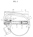
Fig. 1 is a front view showing the present invention. -
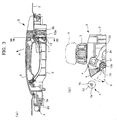
Fig. 2 is a back view showing the present invention. -
Fig. 3 is a set of views showing a handle device, and part (a) is a cross-sectional view taken alongline 3A-3A inFig. 1 and part (b) is a cross-sectional view taken alongline 3B-3B in part (a) ofFig. 3 . -
Fig. 4 is a set of views showing a handle base, and part (a) is a back view and part (b) is an enlarged perspective view of a main section. -
Fig. 1 and the following figures show an embodiment of the present invention for coupling a vehicle'soutside handle device 5 anddoor lock device 6 with anoperation cable 7. - The
handle device 5 is formed by coupling anoperation handle 3 of a grip shape long in the vehicle length direction to ahandle base 2. Thehandle device 5 is capable of turning operation between an initial rotational position shown inFig. 3 and an operative rotational position to which thehandle device 5 is rotationally operated in the direction of arrow A inFig. 3 about arotational center 3a formed at the end thereof at the front side of the vehicle (left side inFig. 3 ). - Moreover, at the tip end of the
operation handle 3 at the circumference of the rotation thereof, anoperation leg 3b is formed to protrude toward the inside of a door 1. Alever 12 and a counterweight (movable member 8) are coupled to thehandle base 2 rotatably about arotation shaft 12b. Thelever 12 includes anactuation piece 12a that is configured to be locked on theoperation leg 3b. Thecounterweight 8 is coupled to thelever 12. - The
lever 12 is capable of turning from an initial rotational position which corresponds to the initial rotational position of the operation handle 3 to an operative rotational position which corresponds to the operative rotational position of theoperation handle 3. Thelever 12 is urged toward the initial rotational position by urging force applied to thecounterweight 8 by atorsion spring 13. - The
counterweight 8 is disposed along one side edge of thehandle base 2 and has a weight necessary to cancel out a force that operates thelever 12 toward its operative rotational position, the force originating from an inertia force in a direction of opening the door 1 of the vehicle that is exerted on the operation handle 3 when a lateral collisional force is applied to the door 1. - As shown by chain lines in
Fig. 3 , in response to operation of turning the operation handle 3 from its initial rotational position to operative rotational position against the urging force from thetorsion spring 13 mentioned above, thelever 12 turns from its initial rotational position to operative rotational position and thereby moves a coupling point (output section 4) provided on thelever 12. - Further, as shown in
Figs. 1 and3 , thehandle base 2 is provided with acable coupling section 11. Thecable coupling section 11 serves as a section from which to lead out theoperation cable 7 to be described later, and is disposed at the side edge of thehandle base 2 opposite the side edge thereof at which thecounterweight 8 is mounted, so as to prevent interference with thecounterweight 8. - On the other hand, the
door lock device 6, which is operated by thehandle device 5, includes a latch not shown for folding the door 1 in a closed posture. As shown inFig. 2 , thedoor lock device 6 is affixed to the door 1 at a position in proximity to thehandle device 5 and is operated remotely by thehandle device 5 transmitting operation force, which is applied to thehandle device 5, through theoperation cable 7. - The
operation cable 7 is formed by slidably inserting aninner cable 7b into anouter cable 7a, as shown inFig. 3 , and coupled at one end to thehandle device 5 and the other end to thedoor lock device 6. Moreover, theoperation cable 7 is covered with a sponge-like tube 10 made of urethane form or like over an appropriate region in order to prevent noises generated by theoperation cable 7 hitting a door panel (door 1) during travel and other similar situations. - The
operation cable 7 is coupled to thehandle device 5 by affixing one end of theouter cable 7a to thecable coupling section 11 mentioned above and by coupling the same end of theinner cable 7b to the coupling point 4 on thelever 12. - As shown in
Fig. 2 , thedoor lock device 6 is disposed in proximity to the section where theoperation cable 7 is led out from thehandle device 5. In the case where thehandle device 5 and thedoor lock device 6 are coupled to each other directly by theoperation cable 7, the cable routing distance may be excessively short and a bent section with an excessively small curvature may appear on the routing pathway, thereby making the operational resistance excessively large. In addition, in the event of a collision or the like that results in the widening of the interval between thehandle device 5 and thedoor lock device 6, the interval between the connected ends of theinner cable 7b may be widened and the end of theinner cable 7b connected to thedoor lock device 6 may be pulled, thereby operating thedoor lock device 6 and unintentionally opening the door 1. - To avoid this, in this embodiment, the
operation cable 7 is routed along an extra length securing pathway, as shown inFigs. 1 and2 . The extra length securing pathway is a route that allows theoperation cable 7 to be led out from thehandle device 5 at the end at which theoperation cable 7 is coupled thereto once to the opposite end (front end section), then guided to the rear end section along the side edge of thehandle device 5 opposite its side edge where thecable coupling section 11 is disposed, and returned again to the side edge where thecable coupling section 11 is disposed. The extra length securing pathway therefore surrounds substantially theentire handle device 5. In this way, even when the relative positions of thehandle device 5 and thedoor lock device 6 change, theoperation cable 7 is supplied from the extra length securing pathway and absorbs the positional change, thereby preventing generation of an operation force to thedoor lock device 6. - In order to route the
operation cable 7 along the extra length securing pathway, acable holder 2a is formed at a front end section of thehandle base 2 for clamping theoperation cable 7 in cooperation with the panel of the door 1, as shown in part (a) ofFig. 3 . Further, a corner section of the base end of thecable holder 2a functions as a guide. - Meanwhile, as shown in
Figs. 1 and2 , in the case of routing theoperation cable 7 around thehandle device 5, theoperation cable 7 may possibly enter the motion range of thecounterweight 8, as shown by broken lines. In this case, theoperation cable 7 may be caught on thecounterweight 8 when the operation handle 3 is operated, thereby possibly causing an actuation failure. - To avoid this, in this embodiment, the
handle base 2 is provided with aguide section 9. As shown inFigs. 2 and4 , theguide section 9 is formed in a rectangular plate shape at the periphery on the side where thecounterweight 8 is disposed, at an intermediate section between thecounterweight 8 and thedoor lock device 6. - Near the
counterweight 8, theguide section 9 guides theoperation cable 7 in a direction away from the motion range of thecounterweight 8, which is shown by a chain line inFig. 2 , and therefore ensures prevention of theoperation cable 7 from being caught on thecounterweight 8. - Also, the
operation cable 7 is guided in a state where it is only supported by theguide section 9. Thus, theoperation cable 7 can be easily slid by load in the axial direction and easily separated from theguide section 9 by load in the vehicle width direction. This eliminates a situation where theguide section 9 restricts movement of theoperation cable 7 and blocks the supply of an extra length portion to a dimensionally changed section. - Further, in this example, a plate-shaped
guide member 14 is affixed to the door 1 and appropriately shapes the extra length securing pathway. As shown inFig. 2 , with anelongated guide protrusion 14a, theguide member 14 pushes the side face of theoperation cable 7 toward thehandle device 5 so that the curvature of theoperation cable 7 near thecounterweight 8 can be smaller than that in a free state without the guide by theguide section 9. In this way, theoperation cable 7 is kept away from the motion range of thecounterweight 8. - Like the
guide section 9, theelongated guide protrusion 14a of theguide section 14 only pushes theoperation cable 7 and does therefore not restrict the movement of theoperation cable 7 in the axial direction or in the vehicle width direction. -
- 1
- DOOR
- 2
- HANDLE BASE
- 3
- OPERATION HANDLE
- 4
- OUTPUT SECTION
- 5
- HANDLE DEVICE
- 6
- DOOR LOCK DEVICE
- 7
- OPERATION CABLE
- 8
- MOVABLE MEMBER
- 9
- GUIDE SECTION
- 10
- SPONGE-LIKE TUBE
- 11
- CABLE COUPLING SECTION
Claims (5)
- An operation cable routing structure, comprising:a handle device (5) that is affixed to a door (1) of a vehicle and that outputs, from an output section (4), operation force applied to an operation handle (3) rotatably coupled to a handle base (2);a door lock device (6) that is disposed in proximity to the output section (4) of the handle device (5); andan operation cable (7) that couples the output section (4) of the handle device (5) and the door lock device (6), characterized in thatthe operation cable (7) is coupled from the output section (4) to the door lock device (6) via an extra length securing pathway that substantially encircles the handle device (5), andthe operation cable (7) is movably supported by a guide section (9) provided on the handle base (2) at an intermediate position between a part of the operation cable (7) and a movable member (8) of the handle device (5), to thereby be restricted from entering a motion range of the movable member (8), the part of the operation cable (7) being coupled to the door lock device (6), whereinthe movable member (8) is a counterweight (8), and a lever (12) and the counterweight (8) are coupled to the handle base (2) rotatably about a rotation shaft (12b), and the counterweight (8) is disposed along one side edge of the handle base (2), anda cable holder (2a) is formed at a front end section of the handle base (2) for clamping the operation cable (7) in cooperation with the panel of the door (1), andthe guide section (9) is formed in a rectangular plate shape at the periphery on the side where the counterweight (8) is disposed, at an intermediate section between the counterweight (8) and the door lock device (6).
- The operation cable routing structure according to claim 1, wherein the guide section (9) supports the operation cable (7) such that the operation cable (7) is capable of being separated from the guide section (9) when moved in a vehicle width direction.
- The operation cable routing structure according to claim 1, wherein a sponge-like tube (10) is mounted on a section of the operation cable (7), the section being supported by the guide section (9).
- A handle device (5), comprising:a handle base (2) that is affixed to a door (1) of a vehicle;an operation handle (3) that is rotatably coupled to one end of the handle base (2); andan output section (4) including a counterweight (8) that is rotatably coupled to one side part of another end of the handle base (2), is rotationally driven by displacement of a tip end of the operation handle (3) at a circumference of rotation thereof, and cancels out an inertia force resulting from a lateral collision on the door (1), characterized in thata peripheral section of the handle base (2) opposite a peripheral section thereof on which the output section (4) is pivoted is provided with a cable coupling section (11) to which one end of an operation cable (7) that brings displacement of the output section (4) out is coupled, andthe peripheral section on which the output section (4) is pivoted is provided with a guide section (9) by which the operation cable (7) routed to surround substantially an entire periphery of the handle base (2) is movably supported to thereby be restricted from entering a motion range of the counterweight (8), anda lever (12) and the counterweight (8) are coupled to the handle base (2) rotatably about a rotation shaft (12b), and the counterweight (8) is disposed along one side edge of the handle base (2), anda cable holder (2a) is formed at a front end section of the handle base (2) for clamping the operation cable (7) in cooperation with the panel of the door (1), andthe guide section (9) is formed in a rectangular plate shape at the periphery on the side where the counterweight (8) is disposed, at an intermediate section between the counterweight (8) and the door lock device (6).
- The handle device (5) according to claim 4, wherein the guide section (9) is formed in a rectangular plate shape and, at one side edge, supports the operation cable (7) such that the operation cable (7) is capable of being separated from the guide section (9) when moved in a vehicle width direction.
Applications Claiming Priority (2)
| Application Number | Priority Date | Filing Date | Title |
|---|---|---|---|
| JP2013049371A JP6096008B2 (en) | 2013-03-12 | 2013-03-12 | Operation cable routing structure |
| PCT/JP2014/054481 WO2014141869A1 (en) | 2013-03-12 | 2014-02-25 | Routing structure for operation cable |
Publications (3)
| Publication Number | Publication Date |
|---|---|
| EP2933406A1 EP2933406A1 (en) | 2015-10-21 |
| EP2933406A4 EP2933406A4 (en) | 2016-01-13 |
| EP2933406B1 true EP2933406B1 (en) | 2017-04-12 |
Family
ID=51536544
Family Applications (1)
| Application Number | Title | Priority Date | Filing Date |
|---|---|---|---|
| EP14764725.9A Active EP2933406B1 (en) | 2013-03-12 | 2014-02-25 | Routing structure for operation cable |
Country Status (7)
| Country | Link |
|---|---|
| US (1) | US9333838B2 (en) |
| EP (1) | EP2933406B1 (en) |
| JP (1) | JP6096008B2 (en) |
| KR (1) | KR101798311B1 (en) |
| CN (1) | CN105074107B (en) |
| RU (1) | RU2624192C2 (en) |
| WO (1) | WO2014141869A1 (en) |
Families Citing this family (11)
| Publication number | Priority date | Publication date | Assignee | Title |
|---|---|---|---|---|
| KR101628499B1 (en) * | 2014-10-17 | 2016-06-21 | 현대자동차주식회사 | Structure for preventing door opening at side impact and method for preventing door opening at side impact |
| US10865588B2 (en) | 2015-08-24 | 2020-12-15 | Dan Raz Ltd. | Securing mechanism for a sliding panel |
| US9970214B2 (en) | 2015-11-29 | 2018-05-15 | Dan Raz Ltd | Door or other closable panel with lock-actuating linkage |
| US10487545B2 (en) | 2016-03-03 | 2019-11-26 | Dan Raz Ltd. | Latch arrangement having a stop latch |
| US9988830B2 (en) * | 2016-03-03 | 2018-06-05 | Dan Raz Ltd. | Latch arrangement having a handle |
| DE102016212215A1 (en) * | 2016-07-05 | 2018-01-11 | Volkswagen Aktiengesellschaft | Arrangement for preventing an automatic opening of a vehicle door or flap and vehicle with such an arrangement |
| JP6938132B2 (en) | 2016-11-07 | 2021-09-22 | 株式会社アルファ | Vehicle steering wheel device |
| JP6963410B2 (en) * | 2017-05-19 | 2021-11-10 | 株式会社アルファ | Vehicle steering wheel device |
| US11598125B2 (en) | 2017-09-03 | 2023-03-07 | Dan Raz Ltd. | Latch arrangement |
| KR102518541B1 (en) * | 2017-12-01 | 2023-04-07 | 현대자동차주식회사 | Inside handle with integrated grip |
| JP6744881B2 (en) * | 2018-02-20 | 2020-08-19 | 三井金属アクト株式会社 | Door latch device for automobile |
Family Cites Families (19)
| Publication number | Priority date | Publication date | Assignee | Title |
|---|---|---|---|---|
| JPH0443670U (en) * | 1990-08-20 | 1992-04-14 | ||
| GB2261916A (en) * | 1991-11-30 | 1993-06-02 | Angelo Guerrini | Remotely controlled operation of vehicle doors |
| JP2566840Y2 (en) * | 1992-09-21 | 1998-03-30 | 日産自動車株式会社 | Connecting device for door lock and operating device for automobile |
| US5605363A (en) * | 1995-02-07 | 1997-02-25 | Chrysler Corporation | Sliding door latch control assembly |
| ITTO20011000A1 (en) * | 2001-10-19 | 2003-04-19 | Atoma Roltra Spa | MODULAR LOCK FOR A VEHICLE DOOR AND DOOR PROVIDED WITH SUCH LOCK. |
| JP4095790B2 (en) | 2001-11-12 | 2008-06-04 | 株式会社大井製作所 | Door lock device for vehicle door |
| JP4108455B2 (en) * | 2002-11-25 | 2008-06-25 | 三井金属鉱業株式会社 | Door latch device |
| JP2005035453A (en) * | 2003-07-17 | 2005-02-10 | Nissan Motor Co Ltd | Door lock device for vehicle door |
| US7448166B2 (en) * | 2005-02-14 | 2008-11-11 | Toyota Motor Engineering & Manufacturing North America, Inc. | Cable guide mechanism for luggage handles |
| US7568744B2 (en) * | 2005-09-22 | 2009-08-04 | Nissan Technical Center North America, Inc. | Vehicle door handle assembly |
| JP4633599B2 (en) | 2005-10-28 | 2011-02-16 | 本田技研工業株式会社 | Hood lock release cable routing structure |
| US8069616B2 (en) * | 2007-09-07 | 2011-12-06 | Brose Schliesssysteme Gmbh & Co. Kg | Method for mounting a motor vehicle door lock |
| ITMI20071748A1 (en) * | 2007-09-11 | 2009-03-12 | Valeo Sicurezza Abitacolo Spa | SAFETY HANDLE FOR VEHICLES |
| US8576047B2 (en) * | 2008-03-13 | 2013-11-05 | Huf Hulsbeck & Furst Gmbh & Co. Kg | Motor vehicle outside door handle with a sensor module |
| US8152209B2 (en) * | 2008-03-31 | 2012-04-10 | Illinois Tool Works Inc. | Delay apparatus for opening of vehicle door |
| JP4839467B2 (en) * | 2008-05-13 | 2011-12-21 | 三井金属アクト株式会社 | Automotive door |
| IT1397430B1 (en) | 2009-12-11 | 2013-01-10 | Illinois Tool Works | HANDLE GROUP FOR A VEHICLE DOOR. |
| CN102654004B (en) * | 2011-03-02 | 2014-12-17 | 布罗斯锁闭系统有限责任两合公司 | Motor vehicle lock |
| JP5767016B2 (en) * | 2011-05-12 | 2015-08-19 | 株式会社アルファ | Cable connection structure to movable member |
-
2013
- 2013-03-12 JP JP2013049371A patent/JP6096008B2/en active Active
-
2014
- 2014-02-25 CN CN201480010400.9A patent/CN105074107B/en active Active
- 2014-02-25 KR KR1020157027620A patent/KR101798311B1/en active IP Right Grant
- 2014-02-25 WO PCT/JP2014/054481 patent/WO2014141869A1/en active Application Filing
- 2014-02-25 EP EP14764725.9A patent/EP2933406B1/en active Active
- 2014-02-25 RU RU2015139517A patent/RU2624192C2/en not_active IP Right Cessation
- 2014-02-25 US US14/766,143 patent/US9333838B2/en active Active
Non-Patent Citations (1)
| Title |
|---|
| None * |
Also Published As
| Publication number | Publication date |
|---|---|
| JP6096008B2 (en) | 2017-03-15 |
| WO2014141869A1 (en) | 2014-09-18 |
| US9333838B2 (en) | 2016-05-10 |
| CN105074107A (en) | 2015-11-18 |
| EP2933406A4 (en) | 2016-01-13 |
| RU2015139517A (en) | 2017-04-17 |
| CN105074107B (en) | 2018-01-19 |
| RU2624192C2 (en) | 2017-06-30 |
| KR20150130365A (en) | 2015-11-23 |
| EP2933406A1 (en) | 2015-10-21 |
| KR101798311B1 (en) | 2017-11-15 |
| US20160001643A1 (en) | 2016-01-07 |
| JP2014173385A (en) | 2014-09-22 |
Similar Documents
| Publication | Publication Date | Title |
|---|---|---|
| EP2933406B1 (en) | Routing structure for operation cable | |
| KR101932807B1 (en) | Handle device for vehicle | |
| JP5039015B2 (en) | Vehicle door handle device | |
| JP4015635B2 (en) | Vehicle door handle device | |
| JP5418549B2 (en) | Vehicle door outer handle device | |
| EP2169148B1 (en) | Door handle device for vehicle | |
| US20090001734A1 (en) | Door latch apparatus for vehicle | |
| WO2012153572A1 (en) | Cable connection structure for movable member | |
| WO2017078121A1 (en) | Locking apparatus | |
| JP5952285B2 (en) | Vehicle door handle with two levers | |
| JP2007106233A (en) | Armrest structure | |
| WO2016148181A1 (en) | Door handle device for vehicle | |
| JP5764223B2 (en) | Vehicle door | |
| JP4882306B2 (en) | Engine hood lock device | |
| JP5926106B2 (en) | Vehicle door structure | |
| JP5447779B2 (en) | Opener structure | |
| EP2687654B1 (en) | Handle configuration | |
| JP6700036B2 (en) | Cable operating structure | |
| JP2015040377A (en) | Handle device for vehicle | |
| JP2015000681A (en) | Vehicular pop-up hood device | |
| JP2006290230A (en) | Jump-up type hood structure | |
| JP4095790B2 (en) | Door lock device for vehicle door | |
| JP6286177B2 (en) | Power supply structure for sliding door | |
| JP5582845B2 (en) | Vehicle door handle device | |
| JP2007297002A (en) | Steering column mounting structure |
Legal Events
| Date | Code | Title | Description |
|---|---|---|---|
| PUAI | Public reference made under article 153(3) epc to a published international application that has entered the european phase |
Free format text: ORIGINAL CODE: 0009012 |
|
| 17P | Request for examination filed |
Effective date: 20150716 |
|
| AK | Designated contracting states |
Kind code of ref document: A1 Designated state(s): AL AT BE BG CH CY CZ DE DK EE ES FI FR GB GR HR HU IE IS IT LI LT LU LV MC MK MT NL NO PL PT RO RS SE SI SK SM TR |
|
| AX | Request for extension of the european patent |
Extension state: BA ME |
|
| A4 | Supplementary search report drawn up and despatched |
Effective date: 20151210 |
|
| RIC1 | Information provided on ipc code assigned before grant |
Ipc: E05B 79/22 20140101AFI20151204BHEP Ipc: E05B 77/36 20140101ALI20151204BHEP Ipc: E05B 77/04 20140101ALI20151204BHEP Ipc: E05B 77/06 20140101ALI20151204BHEP Ipc: B60J 5/04 20060101ALI20151204BHEP Ipc: E05B 79/20 20140101ALI20151204BHEP Ipc: E05B 85/16 20140101ALI20151204BHEP |
|
| DAX | Request for extension of the european patent (deleted) | ||
| GRAP | Despatch of communication of intention to grant a patent |
Free format text: ORIGINAL CODE: EPIDOSNIGR1 |
|
| GRAS | Grant fee paid |
Free format text: ORIGINAL CODE: EPIDOSNIGR3 |
|
| INTG | Intention to grant announced |
Effective date: 20170208 |
|
| GRAA | (expected) grant |
Free format text: ORIGINAL CODE: 0009210 |
|
| AK | Designated contracting states |
Kind code of ref document: B1 Designated state(s): AL AT BE BG CH CY CZ DE DK EE ES FI FR GB GR HR HU IE IS IT LI LT LU LV MC MK MT NL NO PL PT RO RS SE SI SK SM TR |
|
| REG | Reference to a national code |
Ref country code: GB Ref legal event code: FG4D |
|
| REG | Reference to a national code |
Ref country code: CH Ref legal event code: EP |
|
| REG | Reference to a national code |
Ref country code: IE Ref legal event code: FG4D |
|
| REG | Reference to a national code |
Ref country code: AT Ref legal event code: REF Ref document number: 884052 Country of ref document: AT Kind code of ref document: T Effective date: 20170515 |
|
| REG | Reference to a national code |
Ref country code: DE Ref legal event code: R096 Ref document number: 602014008617 Country of ref document: DE |
|
| REG | Reference to a national code |
Ref country code: NL Ref legal event code: MP Effective date: 20170412 |
|
| REG | Reference to a national code |
Ref country code: LT Ref legal event code: MG4D |
|
| REG | Reference to a national code |
Ref country code: AT Ref legal event code: MK05 Ref document number: 884052 Country of ref document: AT Kind code of ref document: T Effective date: 20170412 |
|
| PG25 | Lapsed in a contracting state [announced via postgrant information from national office to epo] |
Ref country code: NL Free format text: LAPSE BECAUSE OF FAILURE TO SUBMIT A TRANSLATION OF THE DESCRIPTION OR TO PAY THE FEE WITHIN THE PRESCRIBED TIME-LIMIT Effective date: 20170412 |
|
| PG25 | Lapsed in a contracting state [announced via postgrant information from national office to epo] |
Ref country code: FI Free format text: LAPSE BECAUSE OF FAILURE TO SUBMIT A TRANSLATION OF THE DESCRIPTION OR TO PAY THE FEE WITHIN THE PRESCRIBED TIME-LIMIT Effective date: 20170412 Ref country code: AT Free format text: LAPSE BECAUSE OF FAILURE TO SUBMIT A TRANSLATION OF THE DESCRIPTION OR TO PAY THE FEE WITHIN THE PRESCRIBED TIME-LIMIT Effective date: 20170412 Ref country code: GR Free format text: LAPSE BECAUSE OF FAILURE TO SUBMIT A TRANSLATION OF THE DESCRIPTION OR TO PAY THE FEE WITHIN THE PRESCRIBED TIME-LIMIT Effective date: 20170713 Ref country code: HR Free format text: LAPSE BECAUSE OF FAILURE TO SUBMIT A TRANSLATION OF THE DESCRIPTION OR TO PAY THE FEE WITHIN THE PRESCRIBED TIME-LIMIT Effective date: 20170412 Ref country code: LT Free format text: LAPSE BECAUSE OF FAILURE TO SUBMIT A TRANSLATION OF THE DESCRIPTION OR TO PAY THE FEE WITHIN THE PRESCRIBED TIME-LIMIT Effective date: 20170412 Ref country code: ES Free format text: LAPSE BECAUSE OF FAILURE TO SUBMIT A TRANSLATION OF THE DESCRIPTION OR TO PAY THE FEE WITHIN THE PRESCRIBED TIME-LIMIT Effective date: 20170412 Ref country code: NO Free format text: LAPSE BECAUSE OF FAILURE TO SUBMIT A TRANSLATION OF THE DESCRIPTION OR TO PAY THE FEE WITHIN THE PRESCRIBED TIME-LIMIT Effective date: 20170712 |
|
| PG25 | Lapsed in a contracting state [announced via postgrant information from national office to epo] |
Ref country code: BG Free format text: LAPSE BECAUSE OF FAILURE TO SUBMIT A TRANSLATION OF THE DESCRIPTION OR TO PAY THE FEE WITHIN THE PRESCRIBED TIME-LIMIT Effective date: 20170712 Ref country code: IS Free format text: LAPSE BECAUSE OF FAILURE TO SUBMIT A TRANSLATION OF THE DESCRIPTION OR TO PAY THE FEE WITHIN THE PRESCRIBED TIME-LIMIT Effective date: 20170812 Ref country code: PL Free format text: LAPSE BECAUSE OF FAILURE TO SUBMIT A TRANSLATION OF THE DESCRIPTION OR TO PAY THE FEE WITHIN THE PRESCRIBED TIME-LIMIT Effective date: 20170412 Ref country code: SE Free format text: LAPSE BECAUSE OF FAILURE TO SUBMIT A TRANSLATION OF THE DESCRIPTION OR TO PAY THE FEE WITHIN THE PRESCRIBED TIME-LIMIT Effective date: 20170412 Ref country code: RS Free format text: LAPSE BECAUSE OF FAILURE TO SUBMIT A TRANSLATION OF THE DESCRIPTION OR TO PAY THE FEE WITHIN THE PRESCRIBED TIME-LIMIT Effective date: 20170412 Ref country code: LV Free format text: LAPSE BECAUSE OF FAILURE TO SUBMIT A TRANSLATION OF THE DESCRIPTION OR TO PAY THE FEE WITHIN THE PRESCRIBED TIME-LIMIT Effective date: 20170412 |
|
| REG | Reference to a national code |
Ref country code: FR Ref legal event code: PLFP Year of fee payment: 5 |
|
| REG | Reference to a national code |
Ref country code: DE Ref legal event code: R097 Ref document number: 602014008617 Country of ref document: DE |
|
| PG25 | Lapsed in a contracting state [announced via postgrant information from national office to epo] |
Ref country code: SK Free format text: LAPSE BECAUSE OF FAILURE TO SUBMIT A TRANSLATION OF THE DESCRIPTION OR TO PAY THE FEE WITHIN THE PRESCRIBED TIME-LIMIT Effective date: 20170412 Ref country code: CZ Free format text: LAPSE BECAUSE OF FAILURE TO SUBMIT A TRANSLATION OF THE DESCRIPTION OR TO PAY THE FEE WITHIN THE PRESCRIBED TIME-LIMIT Effective date: 20170412 Ref country code: DK Free format text: LAPSE BECAUSE OF FAILURE TO SUBMIT A TRANSLATION OF THE DESCRIPTION OR TO PAY THE FEE WITHIN THE PRESCRIBED TIME-LIMIT Effective date: 20170412 Ref country code: EE Free format text: LAPSE BECAUSE OF FAILURE TO SUBMIT A TRANSLATION OF THE DESCRIPTION OR TO PAY THE FEE WITHIN THE PRESCRIBED TIME-LIMIT Effective date: 20170412 Ref country code: RO Free format text: LAPSE BECAUSE OF FAILURE TO SUBMIT A TRANSLATION OF THE DESCRIPTION OR TO PAY THE FEE WITHIN THE PRESCRIBED TIME-LIMIT Effective date: 20170412 |
|
| PGFP | Annual fee paid to national office [announced via postgrant information from national office to epo] |
Ref country code: FR Payment date: 20171215 Year of fee payment: 5 |
|
| PLBE | No opposition filed within time limit |
Free format text: ORIGINAL CODE: 0009261 |
|
| STAA | Information on the status of an ep patent application or granted ep patent |
Free format text: STATUS: NO OPPOSITION FILED WITHIN TIME LIMIT |
|
| PG25 | Lapsed in a contracting state [announced via postgrant information from national office to epo] |
Ref country code: SM Free format text: LAPSE BECAUSE OF FAILURE TO SUBMIT A TRANSLATION OF THE DESCRIPTION OR TO PAY THE FEE WITHIN THE PRESCRIBED TIME-LIMIT Effective date: 20170412 Ref country code: IT Free format text: LAPSE BECAUSE OF FAILURE TO SUBMIT A TRANSLATION OF THE DESCRIPTION OR TO PAY THE FEE WITHIN THE PRESCRIBED TIME-LIMIT Effective date: 20170412 |
|
| 26N | No opposition filed |
Effective date: 20180115 |
|
| PG25 | Lapsed in a contracting state [announced via postgrant information from national office to epo] |
Ref country code: SI Free format text: LAPSE BECAUSE OF FAILURE TO SUBMIT A TRANSLATION OF THE DESCRIPTION OR TO PAY THE FEE WITHIN THE PRESCRIBED TIME-LIMIT Effective date: 20170412 |
|
| REG | Reference to a national code |
Ref country code: CH Ref legal event code: PL |
|
| PG25 | Lapsed in a contracting state [announced via postgrant information from national office to epo] |
Ref country code: MC Free format text: LAPSE BECAUSE OF FAILURE TO SUBMIT A TRANSLATION OF THE DESCRIPTION OR TO PAY THE FEE WITHIN THE PRESCRIBED TIME-LIMIT Effective date: 20170412 |
|
| REG | Reference to a national code |
Ref country code: IE Ref legal event code: MM4A |
|
| REG | Reference to a national code |
Ref country code: BE Ref legal event code: MM Effective date: 20180228 |
|
| PG25 | Lapsed in a contracting state [announced via postgrant information from national office to epo] |
Ref country code: CH Free format text: LAPSE BECAUSE OF NON-PAYMENT OF DUE FEES Effective date: 20180228 Ref country code: LI Free format text: LAPSE BECAUSE OF NON-PAYMENT OF DUE FEES Effective date: 20180228 Ref country code: LU Free format text: LAPSE BECAUSE OF NON-PAYMENT OF DUE FEES Effective date: 20180225 |
|
| PG25 | Lapsed in a contracting state [announced via postgrant information from national office to epo] |
Ref country code: IE Free format text: LAPSE BECAUSE OF NON-PAYMENT OF DUE FEES Effective date: 20180225 |
|
| PG25 | Lapsed in a contracting state [announced via postgrant information from national office to epo] |
Ref country code: BE Free format text: LAPSE BECAUSE OF NON-PAYMENT OF DUE FEES Effective date: 20180228 |
|
| PG25 | Lapsed in a contracting state [announced via postgrant information from national office to epo] |
Ref country code: MT Free format text: LAPSE BECAUSE OF NON-PAYMENT OF DUE FEES Effective date: 20180225 |
|
| PG25 | Lapsed in a contracting state [announced via postgrant information from national office to epo] |
Ref country code: FR Free format text: LAPSE BECAUSE OF NON-PAYMENT OF DUE FEES Effective date: 20190228 |
|
| PG25 | Lapsed in a contracting state [announced via postgrant information from national office to epo] |
Ref country code: TR Free format text: LAPSE BECAUSE OF FAILURE TO SUBMIT A TRANSLATION OF THE DESCRIPTION OR TO PAY THE FEE WITHIN THE PRESCRIBED TIME-LIMIT Effective date: 20170412 |
|
| PGFP | Annual fee paid to national office [announced via postgrant information from national office to epo] |
Ref country code: GB Payment date: 20191205 Year of fee payment: 7 |
|
| PG25 | Lapsed in a contracting state [announced via postgrant information from national office to epo] |
Ref country code: PT Free format text: LAPSE BECAUSE OF FAILURE TO SUBMIT A TRANSLATION OF THE DESCRIPTION OR TO PAY THE FEE WITHIN THE PRESCRIBED TIME-LIMIT Effective date: 20170412 |
|
| PG25 | Lapsed in a contracting state [announced via postgrant information from national office to epo] |
Ref country code: MK Free format text: LAPSE BECAUSE OF NON-PAYMENT OF DUE FEES Effective date: 20170412 Ref country code: HU Free format text: LAPSE BECAUSE OF FAILURE TO SUBMIT A TRANSLATION OF THE DESCRIPTION OR TO PAY THE FEE WITHIN THE PRESCRIBED TIME-LIMIT; INVALID AB INITIO Effective date: 20140225 Ref country code: CY Free format text: LAPSE BECAUSE OF FAILURE TO SUBMIT A TRANSLATION OF THE DESCRIPTION OR TO PAY THE FEE WITHIN THE PRESCRIBED TIME-LIMIT Effective date: 20170412 |
|
| PG25 | Lapsed in a contracting state [announced via postgrant information from national office to epo] |
Ref country code: AL Free format text: LAPSE BECAUSE OF FAILURE TO SUBMIT A TRANSLATION OF THE DESCRIPTION OR TO PAY THE FEE WITHIN THE PRESCRIBED TIME-LIMIT Effective date: 20170412 |
|
| GBPC | Gb: european patent ceased through non-payment of renewal fee |
Effective date: 20210225 |
|
| PG25 | Lapsed in a contracting state [announced via postgrant information from national office to epo] |
Ref country code: GB Free format text: LAPSE BECAUSE OF NON-PAYMENT OF DUE FEES Effective date: 20210225 |
|
| PGFP | Annual fee paid to national office [announced via postgrant information from national office to epo] |
Ref country code: DE Payment date: 20220620 Year of fee payment: 10 |