WO2014136348A1 - 非調質型軟窒化部品 - Google Patents
非調質型軟窒化部品 Download PDFInfo
- Publication number
- WO2014136348A1 WO2014136348A1 PCT/JP2013/083439 JP2013083439W WO2014136348A1 WO 2014136348 A1 WO2014136348 A1 WO 2014136348A1 JP 2013083439 W JP2013083439 W JP 2013083439W WO 2014136348 A1 WO2014136348 A1 WO 2014136348A1
- Authority
- WO
- WIPO (PCT)
- Prior art keywords
- less
- bending
- hardness
- tempered
- compound layer
- Prior art date
- Legal status (The legal status is an assumption and is not a legal conclusion. Google has not performed a legal analysis and makes no representation as to the accuracy of the status listed.)
- Ceased
Links
Images

Classifications
-
- C—CHEMISTRY; METALLURGY
- C21—METALLURGY OF IRON
- C21D—MODIFYING THE PHYSICAL STRUCTURE OF FERROUS METALS; GENERAL DEVICES FOR HEAT TREATMENT OF FERROUS OR NON-FERROUS METALS OR ALLOYS; MAKING METAL MALLEABLE, e.g. BY DECARBURISATION OR TEMPERING
- C21D9/00—Heat treatment, e.g. annealing, hardening, quenching or tempering, adapted for particular articles; Furnaces therefor
- C21D9/30—Heat treatment, e.g. annealing, hardening, quenching or tempering, adapted for particular articles; Furnaces therefor for crankshafts; for camshafts
-
- B—PERFORMING OPERATIONS; TRANSPORTING
- B60—VEHICLES IN GENERAL
- B60W—CONJOINT CONTROL OF VEHICLE SUB-UNITS OF DIFFERENT TYPE OR DIFFERENT FUNCTION; CONTROL SYSTEMS SPECIALLY ADAPTED FOR HYBRID VEHICLES; ROAD VEHICLE DRIVE CONTROL SYSTEMS FOR PURPOSES NOT RELATED TO THE CONTROL OF A PARTICULAR SUB-UNIT
- B60W10/00—Conjoint control of vehicle sub-units of different type or different function
- B60W10/24—Conjoint control of vehicle sub-units of different type or different function including control of energy storage means
- B60W10/26—Conjoint control of vehicle sub-units of different type or different function including control of energy storage means for electrical energy, e.g. batteries or capacitors
-
- B—PERFORMING OPERATIONS; TRANSPORTING
- B60—VEHICLES IN GENERAL
- B60W—CONJOINT CONTROL OF VEHICLE SUB-UNITS OF DIFFERENT TYPE OR DIFFERENT FUNCTION; CONTROL SYSTEMS SPECIALLY ADAPTED FOR HYBRID VEHICLES; ROAD VEHICLE DRIVE CONTROL SYSTEMS FOR PURPOSES NOT RELATED TO THE CONTROL OF A PARTICULAR SUB-UNIT
- B60W10/00—Conjoint control of vehicle sub-units of different type or different function
- B60W10/24—Conjoint control of vehicle sub-units of different type or different function including control of energy storage means
-
- B—PERFORMING OPERATIONS; TRANSPORTING
- B60—VEHICLES IN GENERAL
- B60W—CONJOINT CONTROL OF VEHICLE SUB-UNITS OF DIFFERENT TYPE OR DIFFERENT FUNCTION; CONTROL SYSTEMS SPECIALLY ADAPTED FOR HYBRID VEHICLES; ROAD VEHICLE DRIVE CONTROL SYSTEMS FOR PURPOSES NOT RELATED TO THE CONTROL OF A PARTICULAR SUB-UNIT
- B60W20/00—Control systems specially adapted for hybrid vehicles
-
- C—CHEMISTRY; METALLURGY
- C21—METALLURGY OF IRON
- C21D—MODIFYING THE PHYSICAL STRUCTURE OF FERROUS METALS; GENERAL DEVICES FOR HEAT TREATMENT OF FERROUS OR NON-FERROUS METALS OR ALLOYS; MAKING METAL MALLEABLE, e.g. BY DECARBURISATION OR TEMPERING
- C21D1/00—General methods or devices for heat treatment, e.g. annealing, hardening, quenching or tempering
- C21D1/06—Surface hardening
-
- C—CHEMISTRY; METALLURGY
- C21—METALLURGY OF IRON
- C21D—MODIFYING THE PHYSICAL STRUCTURE OF FERROUS METALS; GENERAL DEVICES FOR HEAT TREATMENT OF FERROUS OR NON-FERROUS METALS OR ALLOYS; MAKING METAL MALLEABLE, e.g. BY DECARBURISATION OR TEMPERING
- C21D6/00—Heat treatment of ferrous alloys
- C21D6/002—Heat treatment of ferrous alloys containing Cr
-
- C—CHEMISTRY; METALLURGY
- C21—METALLURGY OF IRON
- C21D—MODIFYING THE PHYSICAL STRUCTURE OF FERROUS METALS; GENERAL DEVICES FOR HEAT TREATMENT OF FERROUS OR NON-FERROUS METALS OR ALLOYS; MAKING METAL MALLEABLE, e.g. BY DECARBURISATION OR TEMPERING
- C21D6/00—Heat treatment of ferrous alloys
- C21D6/005—Heat treatment of ferrous alloys containing Mn
-
- C—CHEMISTRY; METALLURGY
- C21—METALLURGY OF IRON
- C21D—MODIFYING THE PHYSICAL STRUCTURE OF FERROUS METALS; GENERAL DEVICES FOR HEAT TREATMENT OF FERROUS OR NON-FERROUS METALS OR ALLOYS; MAKING METAL MALLEABLE, e.g. BY DECARBURISATION OR TEMPERING
- C21D9/00—Heat treatment, e.g. annealing, hardening, quenching or tempering, adapted for particular articles; Furnaces therefor
-
- C—CHEMISTRY; METALLURGY
- C22—METALLURGY; FERROUS OR NON-FERROUS ALLOYS; TREATMENT OF ALLOYS OR NON-FERROUS METALS
- C22C—ALLOYS
- C22C38/00—Ferrous alloys, e.g. steel alloys
-
- C—CHEMISTRY; METALLURGY
- C22—METALLURGY; FERROUS OR NON-FERROUS ALLOYS; TREATMENT OF ALLOYS OR NON-FERROUS METALS
- C22C—ALLOYS
- C22C38/00—Ferrous alloys, e.g. steel alloys
- C22C38/001—Ferrous alloys, e.g. steel alloys containing N
-
- C—CHEMISTRY; METALLURGY
- C22—METALLURGY; FERROUS OR NON-FERROUS ALLOYS; TREATMENT OF ALLOYS OR NON-FERROUS METALS
- C22C—ALLOYS
- C22C38/00—Ferrous alloys, e.g. steel alloys
- C22C38/02—Ferrous alloys, e.g. steel alloys containing silicon
-
- C—CHEMISTRY; METALLURGY
- C22—METALLURGY; FERROUS OR NON-FERROUS ALLOYS; TREATMENT OF ALLOYS OR NON-FERROUS METALS
- C22C—ALLOYS
- C22C38/00—Ferrous alloys, e.g. steel alloys
- C22C38/06—Ferrous alloys, e.g. steel alloys containing aluminium
-
- C—CHEMISTRY; METALLURGY
- C22—METALLURGY; FERROUS OR NON-FERROUS ALLOYS; TREATMENT OF ALLOYS OR NON-FERROUS METALS
- C22C—ALLOYS
- C22C38/00—Ferrous alloys, e.g. steel alloys
- C22C38/18—Ferrous alloys, e.g. steel alloys containing chromium
- C22C38/20—Ferrous alloys, e.g. steel alloys containing chromium with copper
-
- C—CHEMISTRY; METALLURGY
- C22—METALLURGY; FERROUS OR NON-FERROUS ALLOYS; TREATMENT OF ALLOYS OR NON-FERROUS METALS
- C22C—ALLOYS
- C22C38/00—Ferrous alloys, e.g. steel alloys
- C22C38/18—Ferrous alloys, e.g. steel alloys containing chromium
- C22C38/22—Ferrous alloys, e.g. steel alloys containing chromium with molybdenum or tungsten
-
- C—CHEMISTRY; METALLURGY
- C22—METALLURGY; FERROUS OR NON-FERROUS ALLOYS; TREATMENT OF ALLOYS OR NON-FERROUS METALS
- C22C—ALLOYS
- C22C38/00—Ferrous alloys, e.g. steel alloys
- C22C38/18—Ferrous alloys, e.g. steel alloys containing chromium
- C22C38/28—Ferrous alloys, e.g. steel alloys containing chromium with titanium or zirconium
-
- C—CHEMISTRY; METALLURGY
- C22—METALLURGY; FERROUS OR NON-FERROUS ALLOYS; TREATMENT OF ALLOYS OR NON-FERROUS METALS
- C22C—ALLOYS
- C22C38/00—Ferrous alloys, e.g. steel alloys
- C22C38/18—Ferrous alloys, e.g. steel alloys containing chromium
- C22C38/38—Ferrous alloys, e.g. steel alloys containing chromium with more than 1.5% by weight of manganese
-
- C—CHEMISTRY; METALLURGY
- C22—METALLURGY; FERROUS OR NON-FERROUS ALLOYS; TREATMENT OF ALLOYS OR NON-FERROUS METALS
- C22C—ALLOYS
- C22C38/00—Ferrous alloys, e.g. steel alloys
- C22C38/18—Ferrous alloys, e.g. steel alloys containing chromium
- C22C38/40—Ferrous alloys, e.g. steel alloys containing chromium with nickel
- C22C38/42—Ferrous alloys, e.g. steel alloys containing chromium with nickel with copper
-
- C—CHEMISTRY; METALLURGY
- C22—METALLURGY; FERROUS OR NON-FERROUS ALLOYS; TREATMENT OF ALLOYS OR NON-FERROUS METALS
- C22C—ALLOYS
- C22C38/00—Ferrous alloys, e.g. steel alloys
- C22C38/18—Ferrous alloys, e.g. steel alloys containing chromium
- C22C38/40—Ferrous alloys, e.g. steel alloys containing chromium with nickel
- C22C38/58—Ferrous alloys, e.g. steel alloys containing chromium with nickel with more than 1.5% by weight of manganese
-
- C—CHEMISTRY; METALLURGY
- C22—METALLURGY; FERROUS OR NON-FERROUS ALLOYS; TREATMENT OF ALLOYS OR NON-FERROUS METALS
- C22C—ALLOYS
- C22C38/00—Ferrous alloys, e.g. steel alloys
- C22C38/60—Ferrous alloys, e.g. steel alloys containing lead, selenium, tellurium, or antimony, or more than 0.04% by weight of sulfur
Definitions
- the present invention relates to a non-tempered soft nitriding component. More specifically, after forging and machining into the required shape, such as crankshafts and connecting rods used in automobiles, industrial machinery and construction machinery, etc., softening is performed without performing quenching-tempering tempering treatment.
- the present invention relates to a non-tempered soft nitriding component that is manufactured by nitriding treatment and has high bending fatigue strength and excellent bending straightness. More specifically, the present invention relates to a non-tempered nitrocarburized part having a high bending fatigue strength of 750 MPa or more in an excellent bending straightness and a bending fatigue test.
- non-tempered soft nitriding part refers to a part that has been subjected to soft nitriding without being subjected to “quenching-tempering” which is a so-called “tempering” after machining.
- quenching-tempering a so-called “tempering” after machining.
- soft nitriding component the above-mentioned “component subjected to soft nitriding” is simply referred to as “soft nitriding component”.
- processing such as induction hardening and soft nitriding, which are surface hardening treatments, are often performed after forging and machining.
- the above-mentioned “soft nitriding treatment” is a diffusion permeation treatment of nitrogen and carbon at a temperature equal to or lower than the A 1 transformation point.
- the heat treatment temperature is low and the heat treatment strain is small compared to the “induction hardening treatment” It is said.
- a “compound layer” (a layer in which a nitride such as Fe 3 N is deposited) that is observed as white when corroded with nital is formed.
- a “diffusion layer” is formed between the compound layer and the dough (base material).
- the soft nitriding treatment has a small heat treatment strain, but is not completely absent, and has a considerable adverse effect on dimensional accuracy.
- a decrease in dimensional accuracy is a problem even if it is slight. Therefore, it is necessary to improve the dimensional accuracy by performing bending correction after the soft nitriding treatment.
- soft nitrided parts such as crankshafts are required not only to have high bending fatigue strength, but also to have no cracks even when subjected to bending correction, that is, excellent bending correction. .
- crankshaft the above-mentioned soft nitrided part may be represented by “crankshaft”.
- crankshaft which is the main part of the engine, has been aimed at reducing the weight and size without exception.
- extremely high bending fatigue strength of 750 MPa or more has been demanded. Yes.
- the hardness at the position of 0.05 mm from the part surface (hereinafter sometimes referred to as “surface hardness”).
- surface hardness At least Vickers hardness (hereinafter referred to as “HV hardness”) needs to be 400 or more.
- crankshaft shape design is required to have a higher degree of freedom than ever before.
- the crankshaft rope is required to bend and correct even for crankshafts having a shape that is more likely to bend than before when soft nitriding, that is, high bend straightness is required.
- crankshaft having sufficient bending straightness in addition to a bending fatigue strength of 750 MPa or more.
- Patent Document 2 discloses a crankshaft having a pin part and a journal part made of steel having a surface subjected to nitriding treatment or soft nitriding treatment, wherein the steel is used as an alloy component, and C: 0.07% by mass or more.
- Ni 2.4 mass% or more and 4.5 mass% or less
- Al 0.8 mass% or more and 1.5 mass% or less
- Ti 0.5 mass% or more and 1.5 mass% or less
- it further contains one or two of S: 0.01 mass% or more and 0.10 mass%, Ca: 0.0010 mass% or more and 0.0050 mass%, with the balance being Fe and inevitable Sampled from the center made of impurities and unaffected by nitriding After the obtained steel sample is melted at 1200 ° C.
- the temperature range from 900 ° C. to 300 ° C. is set at 0.3 ° C./second to 1.5 ° C./second at an appropriate cooling rate.
- the ratio of bainite in the steel structure can be 80% or more, and the HV hardness can be 200 or more and 300 or less, and the pin portion and the journal portion that have been subjected to the nitriding treatment or soft nitriding treatment
- a “crankshaft” is disclosed in which the internal hardness is 350 to 500 in terms of HV hardness and the HV hardness at a position 0.05 mm from the surface is 650 to 950.
- the inventors of the present invention have a steel material of mass: C: 0.25 to 0.60%, Si: 0.10 to 1.0%, Mn: 0.60 to 2.% by mass. 0%, P: 0.08% or less, S: 0.10% or less, Al: 0.05% or less, Cr: 0.20 to 1.0% and N: 0.0030 to 0.0250%
- the balance is a non-tempered nitrided crankshaft composed of Fe and impurities and satisfying 40 ⁇ C + 2Mn + 5.5Cr ⁇ 43.0, and has an HV hardness of 380 to 600 at a depth of 0.05 mm from the surface.
- a “non-tempered nitrided crankshaft” is proposed in which the compound layer depth of at least the pin fillet portion, journal fillet portion, and pin portion is 5 ⁇ m or less.
- the non-tempered nitrided crankshaft may further contain one or more selected from Cu, Ni, Mo, V, Ti and Ca. In that case, [40 ⁇ C + 2Mn + 5.5Cr + 26Mo ⁇ 43. 0] must be satisfied.
- the inventors of the present invention disclosed in Patent Document 4 that the steel material of the dough is, by mass%, C: 0.25 to 0.40%, Si: 0.10 to 0.35%, Mn: 0.60 to 1.0%, P: 0.08% or less, S: 0.10% or less, Al: 0.05% or less, Cr: 0.30 to 1.10%, and N: 0.0030 to 0.0250%
- a tempered soft nitrided part comprising Fe and impurities in the balance, having an HV hardness of 400 to 600 at a position of 0.05 mm from the surface, and a compound layer depth of 5 ⁇ m or less at the stress concentration portion
- the tempered nitrided part may further include one or more selected from Cu, Mo, V, Ni, and Ti.
- JP 2002-226939 A JP 2007-177309 A JP 2012-2605 A JP 2011-42846 A
- the tempered soft nitriding component disclosed in Patent Document 4 is excellent in bending straightening after soft nitriding, and has a high bending fatigue strength of 800 MPa or more in a bending fatigue test. For this reason, it can be used as a part such as an automobile, an industrial machine, and a construction machine, for example, a crankshaft, and it is possible to cope with a reduction in weight and size.
- it is necessary to perform a tempering treatment of quenching and tempering after machining and before soft nitriding.
- the present invention has been made to solve the above problems, and provides a non-tempered nitrocarburized part that has excellent bending straightness and has a high bending fatigue strength of 750 MPa or more in a bending fatigue test. For the purpose.
- the fracture surface of the test piece from which the compound layer was not removed is a starting point of cracking due to the brittle fracture of the compound layer, In the case of the test piece from which the compound layer is removed, it becomes a ductile fracture surface.
- the hardness at the 0.05 mm position from the component surface is 400 or more in terms of HV hardness, and the hardness at the 1.0 mm position from the component surface (hereinafter “internal hardness”). If the HV hardness is 200 or more, a high bending fatigue strength of 750 MPa or more can be stably obtained.
- Non-tempered parts have a lower base material durability ratio (fatigue strength / tensile strength) than tempered parts. Therefore, even if the non-tempered part has the same internal hardness as the tempered part, the fatigue strength of the base material is lower than that of the tempered part.
- the internal hardness of the non-tempered nitrocarburized part is as low as less than 200 in terms of HV hardness, even if it has a high surface hardness of 400 or more in terms of HV hardness, it will start from the interior during the fatigue test. May occur, and it may be difficult to obtain a high fatigue strength of 750 MPa or more.
- the present invention has been completed based on the above findings, and the gist of the present invention is the non-tempered soft nitriding component shown below.
- a non-tempered soft nitriding component having a compound layer on the surface layer of a steel material wherein the chemical composition of the steel material is C: 0.25 to 0.40%, Si: 0 .10 to 0.35%, Mn: more than 2.0% and 2.8% or less, N: 0.0030 to 0.0250%, Cu: 0 to 1.0%, Mo: 0 to 0.3 %, Ni: 0 to 0.5%, Ti: 0 to 0.020%, balance: Fe and impurities, and P, S, Al and Cr in the impurities are P: 0.08% or less, S: 0.10% or less, Al: 0.05% or less, and Cr: less than 0.20%, HV hardness at 0.05 mm position from the surface is 400 to 480, and HV hardness at 1.0 mm position from the surface
- a non-tempered soft nitriding component having a thickness of 200 or more and a compound layer depth of a stress concentration portion of 5 ⁇ m or less.
- Impurity refers to what is mixed from ore, scrap, or the production environment as raw materials when industrially producing steel materials.
- the “stress concentration portion” refers to a portion where a crack is generated when fatigue fracture due to bending and bending correction are performed.
- the “stress concentration part” means “pin fillet part” or “journal fillet part”. Point to.
- the non-tempered soft nitriding component of the present invention is excellent in bend straightening after nitrocarburizing treatment and has a high bending fatigue strength of 750 MPa or more in a bending fatigue test.
- it can be used as a crankshaft, and it is possible to reduce the weight and size of these components.
- C 0.25 to 0.40%
- C has an effect of increasing the internal fatigue and surface hardness and increasing the bending fatigue strength.
- the C content is set to 0.25 to 0.40%.
- the C content is preferably 0.28% or more, and more preferably 0.38% or less.
- Si 0.10 to 0.35%
- Si is an element necessary for deoxidation at the time of melting, and in order to obtain such an effect, the content needs to be at least 0.10%.
- the Si content is set to 0.10 to 0.35%.
- the Si content is preferably 0.15% or more, and preferably 0.30% or less.
- Mn More than 2.0% and 2.8% or less Mn is an element having a deoxidizing action like Si. Mn also has the effect of increasing the bending fatigue strength by increasing the internal hardness and further increasing the surface layer hardness by increasing the amount of dissolved nitrogen in the surface layer during soft nitriding. In order to exert such an effect, it is necessary to contain Mn in an amount exceeding 2.0%. On the other hand, when the content of Mn exceeds 2.8%, the surface layer hardness becomes excessively high, and even when the compound layer depth of the stress concentration portion is 5 ⁇ m or less, the bending straightness is excessively lowered. Therefore, the Mn content is more than 2.0% and not more than 2.8%. The Mn content is preferably 2.2% or more, and preferably 2.7% or less.
- N 0.0030 to 0.0250%
- N is an element that improves the bending fatigue strength and the bending straightness. In order to acquire such an effect, it is necessary to contain 0.0030% or more of N. On the other hand, the effect is saturated even if it contains N exceeding 0.0250%. Therefore, the N content is set to 0.0030 to 0.0250%.
- the N content is preferably 0.0080% or more, and preferably 0.0220% or less.
- One of the base steel materials of the non-tempered soft nitriding part of the present invention is composed of the above elements C to N, the balance being Fe and impurities, and P, S, Al and Cr in the impurities are P: 0.08% or less, S: 0.10% or less, Al: 0.05% or less, and Cr: less than 0.20%.
- P 0.08% or less
- P is an impurity contained in the steel and reduces the bending fatigue strength.
- the content of P is set to 0.08% or less.
- S 0.10% or less S is an impurity contained in steel. Further, if S is positively contained, there is an effect of improving machinability. However, when the content of S exceeds 0.10%, the bending fatigue strength and the bending straightness are significantly reduced. Therefore, the content of S is set to 0.10% or less. The S content is preferably 0.08% or less. In addition, when obtaining the improvement effect of machinability, it is preferable that content of S shall be 0.04% or more.
- Al 0.05% or less
- Al is an impurity contained in steel.
- the content of Al increases, bending straightness deteriorates.
- the content exceeds 0.05%, the bending straightness is significantly lowered even when the compound layer depth of the stress concentration portion is 5 ⁇ m or less. Therefore, the Al content is set to 0.05% or less.
- the Al content is preferably 0.03% or less.
- Cr Less than 0.20% Cr is an impurity contained in steel. When Cr is contained, the surface layer hardness becomes excessively high and the bending straightness is lowered. Therefore, the Cr content is preferably as low as possible. Therefore, the Cr content is less than 0.20%. The Cr content is preferably 0.10% or less.
- Another one of the base steel materials of the non-tempered soft nitriding part of the present invention contains at least one element selected from Cu, Mo, Ni and Ti instead of a part of Fe. is there.
- Cu and Mo may be contained for the purpose of increasing the bending fatigue strength. This will be described in detail below.
- Cu 0 to 1.0%
- Cu is an element that increases internal hardness and improves bending fatigue strength. Therefore, Cu may be contained. However, when the Cu content exceeds 1.0%, the hot workability is lowered. Therefore, the amount of Cu in the case of inclusion is set to 1.0% or less.
- the amount of Cu is preferably 0.4% or less, and more preferably 0.3% or less.
- the amount of Cu is preferably 0.05% or more, and more preferably 0.1% or more.
- Mo 0 to 0.3% Mo has the effect
- the amount of Mo is preferably 0.05% or more, and more preferably 0.1% or more.
- said Cu and Mo can be contained only in any 1 type in them, or 2 types of composites.
- the total content of these elements may be 1.30%, but is preferably 0.30% or less.
- Ni and Ti may be contained for the purpose of improving the bending straightness. This will be described in detail below.
- Ni 0 to 0.5%
- Ni is an element that improves toughness and improves bend straightening. Therefore, Ni may be included. However, even if Ni is contained in an amount exceeding 0.5%, the above effect is saturated and the economic efficiency is impaired. Therefore, the amount of Ni in the case of inclusion is set to 0.5% or less. Note that the amount of Ni is preferably 0.3% or less, and more preferably 0.2% or less.
- the amount of Ni is preferably 0.05% or more, and more preferably 0.08% or more.
- Ni is combined so that Ni / Cu ⁇ 0.5 is satisfied. Is preferably contained.
- Ti 0 to 0.020%
- Ti is an element that improves bend straightening by forming nitrides, making crystal grains fine, and making cracks difficult to progress during bending straightening. Therefore, Ti may be included. However, when the Ti content exceeds 0.020%, the nitride becomes coarse, and conversely, even if the compound layer depth of the stress concentration portion is 5 ⁇ m or less, the bending straightness is remarkably lowered. Therefore, when Ti is included, the amount of Ti is set to 0.020% or less. The amount of Ti is preferably 0.015% or less.
- the amount of Ti is preferably 0.005% or more.
- said Ni and Ti can be contained only in one of them, or 2 types of composites.
- the total content of these elements may be 0.520%, but is preferably 0.30% or less.
- the non-tempered nitrocarburized part according to the present invention must have an HV hardness of 400 to 480 at a position of 0.05 mm from the surface.
- the HV hardness of the surface layer is 400 or more, and 1.0 mm position from the surface of the part, that is, the internal HV hardness is 200 or more. If the compound layer depth of the part is 5 ⁇ m or less, a high bending fatigue strength of 750 MPa or more can be ensured. However, when the HV hardness of the surface layer exceeds 480, even when the compound layer depth of the stress concentration portion is 5 ⁇ m or less for a crankshaft shape that is more likely to bend than before when soft nitriding. In some cases, it is not possible to obtain practically sufficient bending straightness.
- the tempered soft nitrided part according to the present invention has an HV hardness of 400 to 480 at a position of 0.05 mm from the surface.
- the HV hardness at a position of 0.05 mm from the surface is preferably 410 or more, and preferably 470 or less.
- the non-tempered soft nitriding component according to the present invention must have an HV hardness of 200 or more at a position 1.0 mm from the surface of the component.
- the durability ratio of the base material is lower than that of tempered nitrocarburized parts. Fatigue strength is lower than that of tempered nitrocarburized parts. For this reason, in the non-tempered nitrocarburized part, when the internal HV hardness is less than 200, even if the internal hardness is equal to the tempered part, and the surface hardness of the HV hardness is 400 or higher. Even if it has the thickness, fatigue fracture occurs from the inside, and it may be difficult to obtain a high fatigue strength of 750 MPa or more.
- the non-tempered soft nitriding component according to the present invention has an HV hardness at a position of 1.0 mm from the surface of 200 or more.
- the HV hardness at a position of 1.0 mm from the surface is preferably 210 or more, and preferably 320 or less from the viewpoint of machinability.
- the compound layer depth of the stress concentration part In the non-tempered soft nitriding component according to the present invention, the compound layer depth of the stress concentration portion must be 5 ⁇ m or less.
- the compound layer depth of the stress concentration portion is 5 ⁇ m or less.
- the depth of the compound layer in the stress concentration portion is preferably 3 ⁇ m or less, and it is most preferable that there is no compound layer, that is, the compound layer depth is 0 ⁇ m.
- the parts satisfying the above (B) to (D) are, for example, machined into a hot forged product satisfying the chemical composition defined in the present invention, and then RX gas and ammonia gas are set to 1: 1. It is obtained by holding the mixed temperature in an atmosphere of 600 ° C. for 2 hours for soft nitriding, cooling in 90 ° C. oil, and then polishing the stress concentration portion by mechanical processing such as lapping. *
- RX gas is a kind of modified gas and is a trade name of gas.
- crankshaft is cited as an example of a non-tempered soft nitriding component, for example, a crankshaft manufactured by hot forging a material that satisfies the chemical composition conditions defined in the present invention is used.
- RX gas and ammonia gas are mixed in a 1: 1 ratio and kept in an atmosphere of 600 ° C. for 2 hours for soft nitriding treatment, cooled in 90 ° C. oil, and then the pin fillet part Further, it is obtained by polishing the journal fillet portion by machining such as lapping.
- each steel slab was hot forged under conditions of a heating temperature of 1200 ° C. and a finishing temperature of 1000 to 1050 ° C. to form a steel bar having a diameter of 90 mm.
- the steel bar after hot forging was allowed to cool in the atmosphere and cooled to room temperature.
- steels A to G are examples in which the chemical composition is within the range defined by the present invention
- steels H to K are examples in which the chemical composition is outside the range defined by the present invention.
- the steel bar having a diameter of 90 mm thus obtained was heated to 1200 ° C. and hot forged at a finishing temperature of 1000 to 1050 ° C. to produce a steel bar having a diameter of 50 mm. All finished steel bars were allowed to cool in the atmosphere to room temperature.
- a part of the steel bar having a diameter of 50 mm of steel A is further austenitized under the conditions of heating temperature: 880 ° C. and holding time: 60 minutes, and then allowed to cool in the atmosphere and subjected to normalizing treatment. It was.
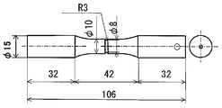
- the groove bottom of R3 is the stress concentration part.
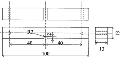
- the notch bottom of R3 becomes the stress concentration portion.
- the grooved Ono rotary bending fatigue test piece and the 4-point bending test piece obtained as described above were soft nitrided by holding RX gas and ammonia gas in a 1: 1 mixture at a temperature of 600 ° C. for 2 hours. Treated and then cooled in 90 ° C. oil.
- the target polishing depth was set to 0.03 mm for the groove bottom of the grooved Ono-type rotary bending fatigue test piece and the notch bottom of the four-point bending test piece. Electropolishing was performed under the following conditions.
- the target polishing depth was set to 0.015 mm for the groove bottom of the grooved Ono-type rotary bending fatigue test piece and the notch bottom of the four-point bending test piece. Electropolishing was performed under the following conditions.
- test piece as it was soft-nitrided (Test No. 13) and the test piece (Test No. 1-12 and Test No. 14-16) electropolished after the soft nitriding,
- the bending fatigue strength was investigated by a bending fatigue test and the bending straightness was investigated by a four-point bending test.
- the target for ⁇ w was 750 MPa or more.
- the target of the bending straightness was determined to be 22000 ⁇ (corresponding to 2.2% of bending straightening strain) or more on the gauge reading.
- the above resin-filled test piece is polished again, corroded with nital, and the R3 groove bottom and R3 notch bottom are arbitrarily observed with an optical microscope at a magnification of 400 times, respectively, and whitened.
- the observed portion was defined as a “compound layer”, the depths thereof were measured, and the arithmetic average was obtained as the compound layer depth.
- the C content of steel H which is a steel material
- the internal hardness of the Ono type rotating bending fatigue test piece is as low as 187 in HV hardness, and ⁇ w does not reach the target of 750 MPa or more, and is inferior in bending fatigue characteristics.
- the Mn content of steel I which is a steel material, is below the range specified in the present invention.
- the surface layer hardness of the Ono type rotating bending fatigue test piece is as low as 332 in HV hardness, ⁇ w does not reach the target of 750 MPa or more, and the bending fatigue characteristics are inferior.
- the Mn content of steel J which is a steel material, exceeds the range specified in the present invention.
- the depth of the compound layer is as small as 1 ⁇ m
- the surface hardness of the 4-point bending test piece is as high as 520 in HV hardness
- the bend correction property has reached the target of 22000 ⁇ or more by gauge reading. It is inferior in bending straightness.
- the Cr content of steel K which is a steel material, exceeds the range specified in the present invention.
- the compound layer depth is as small as 2 ⁇ m
- the surface hardness of the four-point bending test piece is as high as 518 in HV hardness, and the bending straightness has reached the target of 22000 ⁇ or more in gauge reading. It is inferior in bending straightness.
- the compound layer depth of the 4-point bending test piece is out of the conditions defined in the present invention, so that the bending straightness is inferior.
- the chemical composition of steel B which is the base steel material, is within the range specified in the present invention, but the depth of the compound layer of the 4-point bending test piece is as high as 20 ⁇ m, and the bending straightness is gauged. Has not reached the target of 22000 ⁇ or more, and is inferior in bending straightness.
- the chemical composition of steel C which is a steel material, is within the range specified in the present invention, but the depth of the compound layer of the 4-point bending test piece is as high as 11 ⁇ m, and the bending straightness is gauged. Has not reached the target of 22000 ⁇ or more, and is inferior in bending straightness.
- the chemical composition of steel F which is the material of the base steel, is within the range specified in the present invention, but the depth of the compound layer of the 4-point bending test piece is as high as 8 ⁇ m, and the bending straightness is gauged. Has not reached the target of 22000 ⁇ or more, and is inferior in bending straightness.
- the chemical composition of steel G which is a steel material, is within the range specified in the present invention, but the depth of the compound layer of the 4-point bending test piece is as high as 8 ⁇ m, and the bending straightness is gauged. Has not reached the target of 22000 ⁇ or more, and is inferior in bending straightness.
- the non-tempered soft nitriding component of the present invention is excellent in bend straightening after nitrocarburizing treatment and has a high bending fatigue strength of 750 MPa or more in a bending fatigue test.
- it can be used as a crankshaft and can cope with light weight and downsizing.
Landscapes
- Chemical & Material Sciences (AREA)
- Engineering & Computer Science (AREA)
- Mechanical Engineering (AREA)
- Materials Engineering (AREA)
- Organic Chemistry (AREA)
- Metallurgy (AREA)
- Crystallography & Structural Chemistry (AREA)
- Physics & Mathematics (AREA)
- Thermal Sciences (AREA)
- Transportation (AREA)
- Combustion & Propulsion (AREA)
- Automation & Control Theory (AREA)
- Heat Treatment Of Articles (AREA)
- Solid-Phase Diffusion Into Metallic Material Surfaces (AREA)
- Heat Treatment Of Steel (AREA)
- Chemical Kinetics & Catalysis (AREA)
Abstract
Description
C:0.25~0.40%
Cは、内部硬さおよび表層硬さを高めて、曲げ疲労強度を高める作用を有する。所望の曲げ疲労強度を得るためには、0.25%以上のCを含有する必要がある。しかしながら、Cの含有量が多くなりすぎると、表層硬さがあまりにも大きくなって、応力集中部の化合物層深さが5μm以下であっても十分な曲げ矯正性を得ることができない。このため、Cの含有量を0.25~0.40%とした。なお、Cの含有量は、0.28%以上とすることが好ましく、また、0.38%以下とすることが好ましい。
Siは、溶製時の脱酸用として必要な元素であり、かかる効果を得るためには少なくとも0.10%の含有量とする必要がある。しかしながら、Siの含有量が多くなりすぎると、応力集中部の化合物層深さが5μm以下であっても曲げ矯正性の過度な低下を招く。このため、Siの含有量を0.10~0.35%とした。なお、Siの含有量は、0.15%以上とすることが好ましく、また、0.30%以下とすることが好ましい。
Mnは、Siと同様に脱酸作用を有する元素である。Mnには、内部硬さを高め、さらに軟窒化時に表層の固溶窒素量を増加させて表層硬さを向上させることにより、曲げ疲労強度を高める作用もある。このような効果を発揮させるためには、2.0%を超える量のMnを含有させる必要がある。一方、Mnの含有量が2.8%を超えると、表層硬さが過剰に高くなって、応力集中部の化合物層深さが5μm以下であっても曲げ矯正性が過度に低下する。したがって、Mnの含有量は2.0%を超えて2.8%以下とした。なお、Mnの含有量は、2.2%以上とすることが好ましく、また、2.7%以下とすることが好ましい。
Nは、曲げ疲労強度および曲げ矯正性を向上させる元素である。このような効果を得るためには、0.0030%以上の量のNを含有させる必要がある。一方、0.0250%を超えるNを含有させてもその効果は飽和する。したがって、Nの含有量は0.0030~0.0250%とした。なお、Nの含有量は、0.0080%以上とすることが好ましく、また、0.0220%以下とすることが好ましい。
Pは、鋼に含有される不純物であり、曲げ疲労強度を低下させてしまう。特に、その含有量が0.08%を超えると、曲げ疲労強度の低下が著しくなる。したがって、Pの含有量を0.08%以下とした。なお、Pの含有量は、0.04%以下とすることが好ましい。
Sは、鋼に含有される不純物である。また、Sを積極的に含有させれば、被削性を向上させる効果を有する。しかしながら、Sの含有量が0.10%を超えると、曲げ疲労強度と曲げ矯正性の著しい低下をきたす。したがって、Sの含有量を0.10%以下とした。Sの含有量は0.08%以下とすることが好ましい。なお、被削性の向上効果を得る場合には、Sの含有量は、0.04%以上とすることが好ましい。
Alは、鋼に含有される不純物である。Alの含有量が多くなると、曲げ矯正性の低下をきたす。特に、その含有量が0.05%を超えると、応力集中部の化合物層深さが5μm以下であっても曲げ矯正性の低下が著しくなる。したがって、Alの含有量を0.05%以下とした。なお、Alの含有量は、0.03%以下とすることが好ましい。
Crは、鋼に含有される不純物である。Crを、含有すると表層硬さが過度に高くなり、曲げ矯正性を低下させるため、Crの含有量はできるだけ低くすることが望ましい。したがって、Crの含有量を0.20%未満とした。Crの含有量は、0.10%以下とすることが好ましい。
Cuは、内部硬さを高めて、曲げ疲労強度を向上させる元素である。したがって、Cuを含有させてもよい。しかしながら、Cuの含有量が1.0%を超えると、熱間加工性の低下をきたす。したがって、含有させる場合のCuの量を1.0%以下とした。なお、Cuの量は、0.4%以下とすることが好ましく、0.3%以下とすれば一層好ましい。
Moは、フェライトを強化し、内部硬さを高めて、曲げ疲労強度を向上させる作用を有する。したがって、Moを含有させてもよい。しかしながら、0.3%を超える量のMoを含有させても上記の効果が飽和して、経済性が損なわれるばかりである。したがって、含有させる場合のMoの量を0.3%以下とした。なお、Moの量は、0.2%以下とすることが好ましい。
Niは、靱性を向上させ、曲げ矯正性を向上させる元素である。したがって、Niを含有させてもよい。しかしながら、0.5%を超える量のNiを含有させても上記の効果が飽和して、経済性が損なわれるばかりである。したがって、含有させる場合のNiの量を0.5%以下とした。なお、Niの量は、0.3%以下とすることが好ましく、0.2%以下とすれば一層好ましい。
Tiは、窒化物を形成し、結晶粒を微細化して曲げ矯正時にクラックを進展させにくくすることで曲げ矯正性を向上させる元素である。したがって、Tiを含有させてもよい。しかしながら、Tiの含有量が0.020%を超えると、窒化物が粗大になり、逆に、応力集中部の化合物層深さが5μm以下であっても曲げ矯正性が著しく低下する。したがって、含有させる場合のTiの量を0.020%以下とした。なお、Tiの量は、0.015%以下とすることが好ましい。
本発明に係る非調質型軟窒化部品は、表面から0.05mm位置のHV硬さが400~480でなければならない。
本発明に係る非調質型軟窒化部品は、該部品の表面から1.0mm位置のHV硬さが200以上でなければならない。
本発明に係る非調質型軟窒化部品は、さらに、その応力集中部の化合物層深さが5μm以下でなければならない。

・電流値:0.14A、
・研磨面積:小野式回転曲げ疲労試験片の場合:160mm2、
4点曲げ試験片の場合:96mm2、
・研磨時間:小野式回転曲げ疲労試験片の場合:970秒、
4点曲げ試験片の場合:590秒。
・電流値:0.14A、
・研磨面積:小野式回転曲げ疲労試験片の場合:160mm2、
4点曲げ試験片の場合:96mm2、
・研磨時間:小野式回転曲げ疲労試験片の場合:490秒、
4点曲げ試験片の場合:300秒。
小野式回転曲げ疲労試験を、室温、大気中、回転数3000rpmの両振りの条件で行い、曲げ疲労強度(以下、「σw」という。)を調査した。
4点曲げ試験片のノッチ底に2mmの歪ゲージを接着し、ゲージが断線するまで曲げ矯正歪を付与した。ゲージが断線した時点でのゲージの読みを曲げ矯正性として評価した。
小野式回転曲げ疲労試験片のR3の溝底縦断部位および4点曲げ試験片のR3のノッチ底縦断部位が被検面になるようにして樹脂に埋め込んだ後、前記の面が鏡面仕上げになるように研磨し、ビッカース硬度計を使用して表面硬さおよび内部硬さを調査した。
前記〈3〉で用いた樹脂埋めした試験片を使用して、化合物層深さの調査を行った。

Claims (3)
- 生地の鋼材の表層に化合物層を有する非調質型軟窒化部品であって、
生地の鋼材の化学組成が、質量%で、
C:0.25~0.40%、
Si:0.10~0.35%、
Mn:2.0%を超えて2.8%以下、
N:0.0030~0.0250%、
Cu:0~1.0%、
Mo:0~0.3%、
Ni:0~0.5%、
Ti:0~0.020%、
残部:Feおよび不純物であり、
不純物中のP、S、AlおよびCrが、
P:0.08%以下、
S:0.10%以下、
Al:0.05%以下および
Cr:0.20%未満であり、
表面から0.05mm位置のHV硬さが400~480であり、
表面から1.0mm位置のHV硬さが200以上であり、かつ
応力集中部の化合物層深さが5μm以下である、
非調質型軟窒化部品。 - 生地の鋼材が、質量%で、Cu:0.05~1.0%およびMo:0.05~0.3%から選択される1種以上を含有する、請求項1に記載の非調質型軟窒化部品。
- 生地の鋼材が、質量%で、Ni:0.05~0.5%およびTi:0.005~0.020%から選択される1種以上を含有する、請求項1または2に記載の非調質型軟窒化部品。
Priority Applications (4)
| Application Number | Priority Date | Filing Date | Title |
|---|---|---|---|
| US14/768,260 US9956950B2 (en) | 2013-03-07 | 2013-12-13 | Non-thermal refined soft-nitrided component |
| JP2015504136A JP5811303B2 (ja) | 2013-03-07 | 2013-12-13 | 非調質型軟窒化部品 |
| CN201380074276.8A CN105026591B (zh) | 2013-03-07 | 2013-12-13 | 非调质型软氮化部件 |
| KR1020157022587A KR101717390B1 (ko) | 2013-03-07 | 2013-12-13 | 비조질형 연질화 부품 |
Applications Claiming Priority (2)
| Application Number | Priority Date | Filing Date | Title |
|---|---|---|---|
| JP2013-045234 | 2013-03-07 | ||
| JP2013045234 | 2013-03-07 |
Publications (1)
| Publication Number | Publication Date |
|---|---|
| WO2014136348A1 true WO2014136348A1 (ja) | 2014-09-12 |
Family
ID=51490890
Family Applications (1)
| Application Number | Title | Priority Date | Filing Date |
|---|---|---|---|
| PCT/JP2013/083439 Ceased WO2014136348A1 (ja) | 2013-03-07 | 2013-12-13 | 非調質型軟窒化部品 |
Country Status (5)
| Country | Link |
|---|---|
| US (1) | US9956950B2 (ja) |
| JP (1) | JP5811303B2 (ja) |
| KR (1) | KR101717390B1 (ja) |
| CN (1) | CN105026591B (ja) |
| WO (1) | WO2014136348A1 (ja) |
Cited By (2)
| Publication number | Priority date | Publication date | Assignee | Title |
|---|---|---|---|---|
| WO2016035519A1 (ja) * | 2014-09-02 | 2016-03-10 | 新日鐵住金株式会社 | 非調質型軟窒化部品 |
| JP2019019411A (ja) * | 2017-07-12 | 2019-02-07 | 三菱製鋼株式会社 | 熱間鍛造用非調質鋼 |
Families Citing this family (1)
| Publication number | Priority date | Publication date | Assignee | Title |
|---|---|---|---|---|
| JP7488491B2 (ja) * | 2020-02-25 | 2024-05-22 | 日本製鉄株式会社 | クランクシャフト及びその製造方法 |
Citations (4)
| Publication number | Priority date | Publication date | Assignee | Title |
|---|---|---|---|---|
| JP2000160287A (ja) * | 1998-11-20 | 2000-06-13 | Sumitomo Metal Ind Ltd | 非調質窒化鍛造部品およびその製造方法 |
| JP2002180194A (ja) * | 2000-12-12 | 2002-06-26 | Sanyo Special Steel Co Ltd | 衝撃特性の異方性に優れる非調質鋼 |
| JP2010242170A (ja) * | 2009-04-06 | 2010-10-28 | Nippon Steel Corp | 靭性に優れた高強度熱間鍛造非調質鋼及びその製造方法 |
| JP2012026005A (ja) * | 2010-07-26 | 2012-02-09 | Sumitomo Metal Ind Ltd | 非調質型窒化クランクシャフト |
Family Cites Families (6)
| Publication number | Priority date | Publication date | Assignee | Title |
|---|---|---|---|---|
| JPH02153042A (ja) * | 1988-12-06 | 1990-06-12 | Kobe Steel Ltd | 熱間鍛造用の高強度・高靭性非調質鋼 |
| JP4716546B2 (ja) | 2000-07-19 | 2011-07-06 | 三菱製鋼室蘭特殊鋼株式会社 | Vを含有しない熱間鍛造用非調質鋼 |
| JP4556334B2 (ja) | 2001-02-01 | 2010-10-06 | 大同特殊鋼株式会社 | 軟窒化用非調質鋼熱間鍛造部品 |
| JP4230794B2 (ja) | 2002-09-25 | 2009-02-25 | 大同特殊鋼株式会社 | 機械部品およびその製造方法 |
| JP2007177309A (ja) | 2005-12-28 | 2007-07-12 | Honda Motor Co Ltd | クランクシャフト及びその製造方法 |
| JP5343760B2 (ja) | 2009-08-24 | 2013-11-13 | 新日鐵住金株式会社 | 調質型軟窒化部品 |
-
2013
- 2013-12-13 JP JP2015504136A patent/JP5811303B2/ja active Active
- 2013-12-13 WO PCT/JP2013/083439 patent/WO2014136348A1/ja not_active Ceased
- 2013-12-13 KR KR1020157022587A patent/KR101717390B1/ko not_active Expired - Fee Related
- 2013-12-13 US US14/768,260 patent/US9956950B2/en active Active
- 2013-12-13 CN CN201380074276.8A patent/CN105026591B/zh active Active
Patent Citations (4)
| Publication number | Priority date | Publication date | Assignee | Title |
|---|---|---|---|---|
| JP2000160287A (ja) * | 1998-11-20 | 2000-06-13 | Sumitomo Metal Ind Ltd | 非調質窒化鍛造部品およびその製造方法 |
| JP2002180194A (ja) * | 2000-12-12 | 2002-06-26 | Sanyo Special Steel Co Ltd | 衝撃特性の異方性に優れる非調質鋼 |
| JP2010242170A (ja) * | 2009-04-06 | 2010-10-28 | Nippon Steel Corp | 靭性に優れた高強度熱間鍛造非調質鋼及びその製造方法 |
| JP2012026005A (ja) * | 2010-07-26 | 2012-02-09 | Sumitomo Metal Ind Ltd | 非調質型窒化クランクシャフト |
Cited By (5)
| Publication number | Priority date | Publication date | Assignee | Title |
|---|---|---|---|---|
| WO2016035519A1 (ja) * | 2014-09-02 | 2016-03-10 | 新日鐵住金株式会社 | 非調質型軟窒化部品 |
| JPWO2016035519A1 (ja) * | 2014-09-02 | 2017-07-27 | 新日鐵住金株式会社 | 非調質型軟窒化部品 |
| US20170275741A1 (en) * | 2014-09-02 | 2017-09-28 | Nippon Steel & Sumitomo Metal Corporation | Non-thermal refined nitrocarburized component |
| JP2019019411A (ja) * | 2017-07-12 | 2019-02-07 | 三菱製鋼株式会社 | 熱間鍛造用非調質鋼 |
| JP7132000B2 (ja) | 2017-07-12 | 2022-09-06 | 三菱製鋼株式会社 | 熱間鍛造用非調質鋼 |
Also Published As
| Publication number | Publication date |
|---|---|
| CN105026591A (zh) | 2015-11-04 |
| JP5811303B2 (ja) | 2015-11-11 |
| US9956950B2 (en) | 2018-05-01 |
| KR101717390B1 (ko) | 2017-03-16 |
| JPWO2014136348A1 (ja) | 2017-02-09 |
| US20150376763A1 (en) | 2015-12-31 |
| KR20150107876A (ko) | 2015-09-23 |
| CN105026591B (zh) | 2017-07-07 |
Similar Documents
| Publication | Publication Date | Title |
|---|---|---|
| JP5521970B2 (ja) | 冷鍛窒化用鋼、冷鍛窒化用鋼材および冷鍛窒化部品 | |
| JP6304386B2 (ja) | 非調質型軟窒化部品 | |
| WO2013140869A1 (ja) | 窒化用鋼材および窒化部品 | |
| JP2019218633A (ja) | 軟窒化用鋼および部品 | |
| JP5343760B2 (ja) | 調質型軟窒化部品 | |
| JP5682486B2 (ja) | 冷鍛窒化用鋼材 | |
| JP2015042766A (ja) | 肌焼鋼鋼材 | |
| JPWO2014017074A1 (ja) | 軟窒化用鋼および軟窒化部品ならびにこれらの製造方法 | |
| JP5499974B2 (ja) | 非調質型窒化クランクシャフト | |
| JP6561816B2 (ja) | クランクシャフト及びその製造方法 | |
| JP5639188B2 (ja) | 軟窒化用非調質鋼および軟窒化部品 | |
| JP5886119B2 (ja) | 肌焼鋼鋼材 | |
| JP2008261037A (ja) | ショットピーニングを施した鋼製の浸炭部品又は浸炭窒化部品 | |
| JP4609585B2 (ja) | 軟窒化用鋼、軟窒化用鋼材およびクランクシャフト | |
| JP5200552B2 (ja) | 調質型軟窒化クランク軸用粗形品および調質型軟窒化クランク軸 | |
| JP5811303B2 (ja) | 非調質型軟窒化部品 | |
| JP5708844B2 (ja) | 非調質型窒化クランクシャフト | |
| JP2011032537A (ja) | 窒化用鋼および窒化部品 | |
| TW201739933A (zh) | 表面硬化鋼 | |
| JP2014043609A (ja) | 時効硬化型軟窒化用鋼 | |
| CN108291286A (zh) | 碳氮共渗用钢材和碳氮共渗零件 |
Legal Events
| Date | Code | Title | Description |
|---|---|---|---|
| WWE | Wipo information: entry into national phase |
Ref document number: IDP00201506173 Country of ref document: ID Ref document number: 201380074276.8 Country of ref document: CN |
|
| 121 | Ep: the epo has been informed by wipo that ep was designated in this application |
Ref document number: 13876867 Country of ref document: EP Kind code of ref document: A1 |
|
| ENP | Entry into the national phase |
Ref document number: 2015504136 Country of ref document: JP Kind code of ref document: A |
|
| WWE | Wipo information: entry into national phase |
Ref document number: 14768260 Country of ref document: US |
|
| ENP | Entry into the national phase |
Ref document number: 20157022587 Country of ref document: KR Kind code of ref document: A |
|
| NENP | Non-entry into the national phase |
Ref country code: DE |
|
| 122 | Ep: pct application non-entry in european phase |
Ref document number: 13876867 Country of ref document: EP Kind code of ref document: A1 |