WO2014136171A1 - Procédé de rénovation d'ascenseur - Google Patents
Procédé de rénovation d'ascenseur Download PDFInfo
- Publication number
- WO2014136171A1 WO2014136171A1 PCT/JP2013/055815 JP2013055815W WO2014136171A1 WO 2014136171 A1 WO2014136171 A1 WO 2014136171A1 JP 2013055815 W JP2013055815 W JP 2013055815W WO 2014136171 A1 WO2014136171 A1 WO 2014136171A1
- Authority
- WO
- WIPO (PCT)
- Prior art keywords
- car
- elevator
- counterweight
- hydraulic jack
- installation area
- Prior art date
Links
Images


Classifications
-
- B—PERFORMING OPERATIONS; TRANSPORTING
- B66—HOISTING; LIFTING; HAULING
- B66B—ELEVATORS; ESCALATORS OR MOVING WALKWAYS
- B66B7/00—Other common features of elevators
-
- B—PERFORMING OPERATIONS; TRANSPORTING
- B66—HOISTING; LIFTING; HAULING
- B66B—ELEVATORS; ESCALATORS OR MOVING WALKWAYS
- B66B19/00—Mining-hoist operation
- B66B19/002—Mining-hoist operation installing or exchanging guide rails
-
- B—PERFORMING OPERATIONS; TRANSPORTING
- B66—HOISTING; LIFTING; HAULING
- B66B—ELEVATORS; ESCALATORS OR MOVING WALKWAYS
- B66B19/00—Mining-hoist operation
- B66B19/007—Mining-hoist operation method for modernisation of elevators
-
- B—PERFORMING OPERATIONS; TRANSPORTING
- B66—HOISTING; LIFTING; HAULING
- B66B—ELEVATORS; ESCALATORS OR MOVING WALKWAYS
- B66B7/00—Other common features of elevators
- B66B7/06—Arrangements of ropes or cables
-
- B—PERFORMING OPERATIONS; TRANSPORTING
- B66—HOISTING; LIFTING; HAULING
- B66B—ELEVATORS; ESCALATORS OR MOVING WALKWAYS
- B66B19/00—Mining-hoist operation
- B66B19/005—Mining-hoist operation installing or exchanging the elevator drive
Definitions
- This invention relates to an elevator repair method for repairing a hydraulic elevator to a machine room-less elevator of a 2: 1 roping method.
- a pair of counterweight guide rails are installed behind the elevator area of the car in the hoistway, alongside the existing hydraulic jack.
- a support beam is installed directly above the hydraulic jack at the upper part of the hoistway.
- a hoisting machine is installed on the support beam. After the repair, the hydraulic jack remains in the hoistway (see, for example, Patent Documents 1 and 2).
- the present invention has been made to solve the above-described problems, and an object of the present invention is to obtain an elevator repair method that can reduce the trouble of repair work.
- the elevator repair method includes a hydraulic elevator in which a hydraulic jack is installed in an equipment installation area, which is an area on either the left or right side of a car in a hoistway when viewed from directly above.
- a 2 1 roping type machine room-less elevator equipped with a counterweight and a pair of counterweight guide rails, wherein at least one of the pair of counterweight guide rails is left with a hydraulic jack.
- the elevator repair method according to the present invention is a hydraulic system in which a hydraulic jack and a pair of hydraulic jack rails are installed in an equipment installation area which is an area on either the left or right side of the car in the hoistway when viewed from directly above.
- the elevator repair method is a hoisting machine in which a hydraulic elevator in which a hydraulic jack is installed in an equipment installation area which is an area on either the left or right side of a car in a hoistway when viewed from directly above.
- a counterweight, and a 2: 1 roping type machine room-less elevator equipped with a pair of counterweight guide rails, in which the hoisting machine remains below the equipment installation area while leaving the hydraulic jack Install the balance weight guide rail in the equipment installation area using the space after removing the hydraulic jack, the process of removing the hydraulic jack from the hoistway, and the balance between the balance weight guide rails.
- FIG. 3 is a plan view showing a schematic layout of main equipment in the elevator before the repair according to the first embodiment. It is a top view which shows the state in the middle of repair of the elevator of FIG. It is a top view which shows the state after repair of the elevator of FIG. It is a top view which shows the schematic layout of the main equipment in the elevator in the middle of repair by Embodiment 2 of this invention. It is a top view which shows the state after repair of the elevator of FIG. It is a perspective view which shows the machine room less elevator renovated with the renovation method of Embodiment 3 of this invention.
- FIG. 10 is a plan view showing a schematic layout of main equipment in an elevator in the middle of refurbishment according to a third embodiment. It is a top view which shows the state after repair of the elevator of FIG.
- FIG. 1 is a perspective view showing a machine room-less elevator refurbished by the refurbishing method of Embodiment 1 of the present invention.
- First to third bases 2 to 4 are fixed to the floor surface at the bottom of the hoistway 1.
- a pair of car guide rails 5a and 5b are installed in parallel and vertically.
- the car 6 is disposed between the car guide rails 5a and 5b, and is moved up and down in the hoistway 1 while being guided by the car guide rails 5a and 5b.
- a pair of car suspension wheels 7 a and 7 b are provided at the lower part of the car 1.
- a pair of counterweight guide rails 8a and 8b are installed in parallel and vertically.
- the counterweight 9 is disposed between the counterweight guide rails 8a and 8b, and is moved up and down in the hoistway 1 while being guided by the counterweight guide rails 8a and 8b.
- a counterweight suspension vehicle 10 is provided on the upper part of the counterweight 9, a counterweight suspension vehicle 10 is provided.
- a hoisting machine 12 is installed on the third base 4 via a hoisting machine base 11.
- the hoisting machine 12 is arranged in the lower part in the hoistway 1.
- a thin hoisting machine having an axial dimension smaller than a dimension in a direction perpendicular to the axial direction is used.
- the hoisting machine 12 has a drive sheave 13 and a hoisting machine main body 14.
- the hoisting machine main body 14 is provided with a hoisting machine motor that rotates the driving sheave 13 and a hoisting machine brake that brakes the rotation of the driving sheave 13.
- a control panel (not shown) for controlling the hoisting machine 12 is installed in the hoistway 1.
- the upper support beam 15 is fixed horizontally near the upper end of the counterweight guide rails 8a and 8b.
- a car return wheel 16 is supported at the lower part of the upper support beam 15.
- a counterweight wheel 17 is supported on the upper support beam 15. The car return wheel 16 and the counterweight return wheel 17 are opposed to the back surface of the car guide rail 5b.
- a car side rope stop 18 is fixed.
- the car-side rope stopper 18 may be fixed to an existing rope clamp on the upper part of the hoistway 1.
- the upper support beam 15 is provided with a counterweight side rope stop 19.
- the car 6 and the counterweight 9 are suspended in the hoistway 1 by the suspension body 20 and are raised and lowered by the hoisting machine 12.
- the suspension body 20 a plurality of ropes or a plurality of belts are used.
- the suspension body 20 includes a first end (cage side end) 20a connected to the car side rope stopper 18 and a second end (balanced weight) connected to the counterweight side rope stopper 19. Side end) 20b.
- the suspension body 20 is wound around the car suspension wheels 7a and 7b, the car return wheel 16, the drive sheave 13, the counterweight return wheel 17 and the counterweight suspension car 10 in order from the first end 20a side. It has been. That is, the car 6 and the counterweight 9 are suspended by a 2: 1 roping method.
- the car guide rails 5 a and 5 b are arranged on the left and right sides of the car 6 in the middle part of the car 6 in the front-rear direction.
- the counterweight guide rails 8a and 8b, the counterweight 9, the hoisting machine 12, the upper support beam 15, the car return wheel 16 and the counterweight return car 17 are the left and right sides of the car in the hoistway 1 as viewed from directly above. It is arranged in the equipment installation area 1a (FIG. 4), which is an area on either side (in this example, the car guide rail 5b side).
- the counterweight 9 is disposed on the front side of the equipment installation area 1a
- the hoisting machine 12 is disposed on the back side of the equipment installation area 1a.
- the hoisting machine 12 is arranged so that the rotation shaft of the drive sheave 13 is horizontal and parallel to the width direction of the car 6 (left-right direction in FIG. 4).
- the hoisting machine 12 is arranged so that the hoisting machine main body 14 is positioned on the lift area side of the car 6 relative to the drive sheave 13.
- the straight line connecting the centers of the car guide rails 5 a and 5 b is parallel to the width direction of the car 6 when viewed from directly above. Furthermore, as viewed from directly above, a straight line connecting the centers of the counterweight guide rails 8a and 8b is parallel to the front-rear direction of the car 6 (the vertical direction in FIG. 4).
- the car suspension wheel 7a is disposed on the front side of the car 6 in the front-rear direction with respect to the car guide rails 5a and 5b.
- the car suspension wheel 7b is arranged behind the car guide rails 5a and 5b in the front-rear direction of the car 6.
- the rotation axes of the car suspension wheels 7a and 7b are parallel to each other and are horizontal.
- the car suspension vehicles 7 a and 7 b are arranged so that the suspension body 20 passing between the car suspension vehicles 7 a and 7 b is inclined with respect to the width direction of the car 6 when viewed from directly above. Further, when viewed from directly above, the suspension body 20 passing between the car suspension wheels 7a and 7b intersects with a straight line connecting the centers of the car guide rails 5a and 5b.
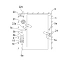
- FIG. 2 is a plan view showing a schematic layout of main equipment in the elevator (hydraulic elevator) before renovation according to the first embodiment.
- a hydraulic jack 21 is installed in a region behind the car guide rail 5b in the device installation region 1a (back side as viewed from the landing).
- First and second upper return wheels (not shown) are provided on the upper portion of the hydraulic jack 21. The first and second upper return wheels are moved up and down by a hydraulic jack 21.
- a pair of hydraulic jack rails 22a and 22b for guiding the vertical movement of the first and second upper return wheels are installed on both sides of the hydraulic jack 21 in parallel and vertically.
- a hydraulic jack rope stopper 23 and a lower return wheel are provided under the hydraulic jack 21, a hydraulic jack rope stopper 23 and a lower return wheel (not shown) are provided under the hydraulic jack 21, a hydraulic jack rope stopper 23 and a lower return wheel (not shown) are provided under the hydraulic jack 21, a hydraulic jack rope stopper 23 and a lower return wheel (not shown) are provided.
- An upper rope stop 24 is provided on the rope holding beam at the upper part of the hoistway 1.
- the car 6 is suspended in the hoistway 1 by a plurality of pre-repair ropes (not shown).
- the pre-renovation rope has a first end connected to the upper leash stop 24 and a second end connected to the hydraulic jack leash 23.
- the rope before repair is wound around the car suspension wheels 7a and 7b, the first upper return wheel, the lower return wheel, and the second upper return wheel in order from the first end side, and the hydraulic jack rope is fastened. Part 23 is reached.
- the period of renovation work in Embodiment 1 is divided into a prior construction period and a continuous suspension period. During the preliminary construction period, it is not necessary to stop the operation of the existing hydraulic elevator continuously.
- the continuous stop period is a period during which any of the existing and new elevators cannot be operated.
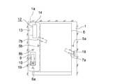
- FIG. 3 is a plan view showing a state during the repair of the elevator shown in FIG.
- the part 19 and the like are installed in the device installation area 1 a in the hoistway 1.
- These devices are installed in a region opposite to the hydraulic jack 21 in the front-rear direction of the car 6 with respect to the car guide rail 5b.
- devices such as the third base 4, the hoisting machine base 11, and the hoisting machine 12 are placed in the lower part of the equipment installation area 1 a by using the space after the removal of the hydraulic jack 21 and the like. Installed.
- a car side rope stop 18 is installed in the upper part of the hoistway 1. Thereafter, the suspension body 20 is arranged as shown in FIG.
- the position of the suspension 20 with respect to the car 6 on the plane layout can be arranged at the same position as the rope before the repair, the car guide rails 5a and 5b, the car 6, the car suspension cars 7a and 7b, and other car peripheral devices, etc. Many existing equipment can be diverted, and production and installation costs can be reduced, construction periods can be shortened, and waste can be reduced.
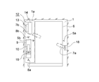
- FIG. 5 is a plan view showing a schematic layout of main equipment in the elevator in the middle of the repair
- FIG. 6 is a plan view showing a state after the repair of the elevator in FIG.
- the counterweight guide rail 8a far from the car guide rail 5b is installed in an empty space in the device installation area 1a during the prior construction period.
- the other machine room-less elevator devices are installed in the hoistway 1 during a continuous stop period after the hydraulic jack 21 and the like are removed.
- the counterweight guide rail 8b is installed in an area behind the car guide rail 5b.
- Other configurations and repair methods are the same as those in the first embodiment.
- the plane space of the counterweight 9 can be increased as compared with the first embodiment, even when the mass of the car 6 is large, it can be dealt with.
- the continuous stop period can be shortened as compared with the case where all the devices are removed.
- the upper support beam 15, the car return wheel 16, the counterweight return wheel 17, and the counterweight side rope stop 19 are supported by the counterweight guide rails 8a and 8b, they are supported in the hoistway 1. There is no need to install pillars or install new support beams in the building, and repair work is easy.
- the position on the plane layout of the suspension body 20 with respect to the car 6 can be arranged at the same position as the rope before repair, the car guide rails 5a and 5b, the car 6, the car suspension cars 7a and 7b, and other car peripheral devices, etc. Many existing equipment can be diverted, and production and installation costs can be reduced, construction periods can be shortened, and waste can be reduced.
- the counterweight guide rail 8a of the counterweight guide rails 8a and 8b is installed in the equipment installation area 1a during the preliminary construction period. However, an empty space in the equipment installation area 1a is used. After installing both the counterweight guide rails 8a and 8b and removing the hydraulic jack 21, etc., the counterweight guide rail 8b is moved, and the distance between the counterweight guide rails 8a and 8b is increased to the required size. May be.
- FIG. 7 is a perspective view showing a machine room-less elevator refurbished by the refurbishing method according to the third embodiment of the present invention.
- the counterweight 9 and the counterweight-side rope stop 19 are arranged on the back side of the equipment installation area 1a when viewed from the landing side, and the hoisting machine 12, the basket return wheel 16, and the fishing
- the combined weight return wheel 17 is arranged on the front side of the device installation area 1a.
- the car suspension wheel 7a is arranged behind the car guide rails 5a and 5b in the front-rear direction of the car 6.
- the car suspension wheel 7b is disposed on the front side of the car 6 in the front-rear direction with respect to the car guide rails 5a and 5b.
- Other configurations are the same as those in the first embodiment.
- FIG. 8 is a plan view showing a schematic layout of main equipment in the elevator in the middle of the repair
- FIG. 9 is a plan view showing a state after the repair of the elevator in FIG.
- the third base 4, the hoisting machine base 11, and the hoisting machine 12 are installed in an empty space in the device installation area 1a during the preliminary construction period.
- the other machine room-less elevator devices are installed in the device installation area 1a using the space after the hydraulic jacks 21 etc. are removed during the continuous stop period after the hydraulic jacks 21 etc. are removed. Further, the mounting positions of the car suspension cars 7 a and 7 b to the car 6 are changed, or the existing car suspension cars 7 a and 7 b are removed, and new car suspension cars 7 a and 7 b are attached to the lower part of the car 6.
- the hydraulic jack rails 22a and 22b are used as the counterweight guide rails 8a and 8b, or the hydraulic jack rails 22a and 22b are removed, and new counterweights are used.
- Guide rails 8a and 8b are installed.
- Other modification methods are the same as those in the first embodiment.
- the pre-construction period can be shortened compared to the second embodiment.
- the hydraulic jack rails 22a and 22b are used as the counterweight guide rails 8a and 8b after repair, the continuous stop period can be shortened as compared with the second embodiment, and the entire construction period is further shortened. be able to.
- Embodiment 3 when the interval between the counterweight guide rails 8a and 8b of the machine room-less elevator after the repair is large and the counterweight guide rail 8b is installed in an empty space in the hydraulic elevator before the repair,
- the counterweight guide rail 8b may be installed during the preliminary construction period. Also, during the prior construction period, both the counterweight guide rails 8a and 8b are installed in the empty space in the equipment installation area 1a, and after removing the hydraulic jack 21 and the like, the counterweight guide rail 8a is moved, The interval between the counterweight guide rails 8a and 8b may be increased to a necessary size.
- the existing car guide rails 5a and 5b, the car 6, the car suspension cars 7a and 7b, etc. do not necessarily have to be diverted to the elevator after the repair. May be replaced as appropriate.
- the device installation area 1a is on the car guide rail 5b side in the hoistway 1, but may be on the car guide rail 5a side.
- the refurbishing method of the present invention can also be applied to an elevator having a device arrangement obtained by inverting the device arrangement of the first to third embodiments in the front-rear direction of the car 6.
Abstract
Priority Applications (4)
| Application Number | Priority Date | Filing Date | Title |
|---|---|---|---|
| CN201380074226.XA CN105026298B (zh) | 2013-03-04 | 2013-03-04 | 电梯的改造方法 |
| US14/761,199 US9676596B2 (en) | 2013-03-04 | 2013-03-04 | Elevator refurbishing method |
| PCT/JP2013/055815 WO2014136171A1 (fr) | 2013-03-04 | 2013-03-04 | Procédé de rénovation d'ascenseur |
| JP2015504015A JP5951104B2 (ja) | 2013-03-04 | 2013-03-04 | エレベータの改修方法 |
Applications Claiming Priority (1)
| Application Number | Priority Date | Filing Date | Title |
|---|---|---|---|
| PCT/JP2013/055815 WO2014136171A1 (fr) | 2013-03-04 | 2013-03-04 | Procédé de rénovation d'ascenseur |
Publications (1)
| Publication Number | Publication Date |
|---|---|
| WO2014136171A1 true WO2014136171A1 (fr) | 2014-09-12 |
Family
ID=51490740
Family Applications (1)
| Application Number | Title | Priority Date | Filing Date |
|---|---|---|---|
| PCT/JP2013/055815 WO2014136171A1 (fr) | 2013-03-04 | 2013-03-04 | Procédé de rénovation d'ascenseur |
Country Status (4)
| Country | Link |
|---|---|
| US (1) | US9676596B2 (fr) |
| JP (1) | JP5951104B2 (fr) |
| CN (1) | CN105026298B (fr) |
| WO (1) | WO2014136171A1 (fr) |
Cited By (3)
| Publication number | Priority date | Publication date | Assignee | Title |
|---|---|---|---|---|
| JP2016147741A (ja) * | 2015-02-12 | 2016-08-18 | 三菱電機株式会社 | エレベータの改修方法および改修されたロープ式エレベータ |
| CN106185534A (zh) * | 2014-10-21 | 2016-12-07 | 三菱电机株式会社 | 无机房电梯的改造方法 |
| JP2017149553A (ja) * | 2016-02-26 | 2017-08-31 | 三菱電機ビルテクノサービス株式会社 | エレベータ機器搬出入方法およびエレベータ機器搬出入装置 |
Families Citing this family (6)
| Publication number | Priority date | Publication date | Assignee | Title |
|---|---|---|---|---|
| WO2014136171A1 (fr) * | 2013-03-04 | 2014-09-12 | 三菱電機株式会社 | Procédé de rénovation d'ascenseur |
| CA2969603A1 (fr) * | 2014-12-16 | 2016-06-23 | Inventio Ag | Systeme d'ascenseur comportant un compartiment machine mobile |
| GR1009066B (el) * | 2016-03-17 | 2017-07-05 | Βαλσαμιδης Aνωνυμη Τεχνικη Εταιρεια Ανελκυστηρων Με Δ.Τ. Βαλσαμιδης Α.Τ.Ε.Α. | Μετατροπη υδραυλικου ανελκυστηρα σε ηλεκτρομηχανικο με εφαρμογη ηλεκτρομηχανολογικων παρεμβασεων |
| JP6250107B1 (ja) * | 2016-07-08 | 2017-12-20 | 三菱電機ビルテクノサービス株式会社 | エレベーター改修方法およびエレベーター改修用ガイドレール支持装置 |
| JP6576567B2 (ja) * | 2016-08-18 | 2019-09-18 | 三菱電機株式会社 | エレベータ改修方法およびエレベータガイドレール |
| CN111232799B (zh) * | 2020-01-10 | 2021-11-26 | 日立电梯(中国)有限公司 | 移动作业平台曳引系统及利用其的无机房电梯施工方法 |
Citations (4)
| Publication number | Priority date | Publication date | Assignee | Title |
|---|---|---|---|---|
| JP2009196786A (ja) * | 2008-02-22 | 2009-09-03 | Hitachi Building Systems Co Ltd | エレベータの改修方法 |
| JP2011251826A (ja) * | 2010-06-03 | 2011-12-15 | Toshiba Elevator Co Ltd | エレベータのリニューアル方法及びリニューアルされたエレベータ装置 |
| JP2012224414A (ja) * | 2011-04-15 | 2012-11-15 | Mitsubishi Electric Corp | エレベータの改修方法、及びエレベータ |
| JP2012240801A (ja) * | 2011-05-20 | 2012-12-10 | Mitsubishi Electric Corp | エレベータ据え替え方法、エレベータのガイドレール仮保持治具 |
Family Cites Families (16)
| Publication number | Priority date | Publication date | Assignee | Title |
|---|---|---|---|---|
| US5899301A (en) * | 1993-12-30 | 1999-05-04 | Kone Oy | Elevator machinery mounted on a guide rail and its installation |
| US6991069B1 (en) * | 1997-12-23 | 2006-01-31 | Inventio Ag | Cable elevator with a drive plate |
| FI109468B (fi) * | 1998-11-05 | 2002-08-15 | Kone Corp | Vetopyörähissi |
| FI111622B (fi) * | 1999-01-27 | 2003-08-29 | Kone Corp | Vetopyörähissi ja taittopyörän käyttö |
| JP4791656B2 (ja) * | 2001-07-03 | 2011-10-12 | オーチス エレベータ カンパニー | 階高可変式ダブルデッキエレベータ |
| JP4468892B2 (ja) * | 2002-11-04 | 2010-05-26 | コネ コーポレイション | カウンタウェイトがないトラクションシーブエレベータ |
| JP2005263490A (ja) * | 2004-03-15 | 2005-09-29 | Inventio Ag | 大荷重用エレベータ |
| FI118641B (fi) * | 2006-06-21 | 2008-01-31 | Kone Corp | Menetelmä ja järjestelmä hississä hissikorin hallitsemattoman liikkeen tunnistamiseksi ja pysäyttämiseksi |
| US8640829B2 (en) * | 2008-07-16 | 2014-02-04 | William P. Block, JR. | Hydraulic elevator system |
| JP4748207B2 (ja) * | 2008-11-12 | 2011-08-17 | 三菱電機ビルテクノサービス株式会社 | 油圧エレベータのリニューアル方法及びその方法によりリニューアルされたロープ式エレベータ |
| JP5448508B2 (ja) | 2009-03-13 | 2014-03-19 | 東芝エレベータ株式会社 | エレベータ設備及びエレベータ設備のリニューアル方法 |
| WO2010148102A1 (fr) * | 2009-06-16 | 2010-12-23 | Wei Tian | Système d'ascenseur sans local de machinerie et procédé pour celui-ci |
| JP2011020804A (ja) | 2009-07-16 | 2011-02-03 | Toshiba Elevator Co Ltd | エレベータのリニューアル方法 |
| JP2011068438A (ja) * | 2009-09-24 | 2011-04-07 | Toshiba Elevator Co Ltd | エレベータのリニューアル方法 |
| JP5595788B2 (ja) * | 2010-05-17 | 2014-09-24 | 東芝エレベータ株式会社 | エレベータのリニューアル方法 |
| WO2014136171A1 (fr) * | 2013-03-04 | 2014-09-12 | 三菱電機株式会社 | Procédé de rénovation d'ascenseur |
-
2013
- 2013-03-04 WO PCT/JP2013/055815 patent/WO2014136171A1/fr active Application Filing
- 2013-03-04 JP JP2015504015A patent/JP5951104B2/ja active Active
- 2013-03-04 US US14/761,199 patent/US9676596B2/en not_active Expired - Fee Related
- 2013-03-04 CN CN201380074226.XA patent/CN105026298B/zh active Active
Patent Citations (4)
| Publication number | Priority date | Publication date | Assignee | Title |
|---|---|---|---|---|
| JP2009196786A (ja) * | 2008-02-22 | 2009-09-03 | Hitachi Building Systems Co Ltd | エレベータの改修方法 |
| JP2011251826A (ja) * | 2010-06-03 | 2011-12-15 | Toshiba Elevator Co Ltd | エレベータのリニューアル方法及びリニューアルされたエレベータ装置 |
| JP2012224414A (ja) * | 2011-04-15 | 2012-11-15 | Mitsubishi Electric Corp | エレベータの改修方法、及びエレベータ |
| JP2012240801A (ja) * | 2011-05-20 | 2012-12-10 | Mitsubishi Electric Corp | エレベータ据え替え方法、エレベータのガイドレール仮保持治具 |
Cited By (3)
| Publication number | Priority date | Publication date | Assignee | Title |
|---|---|---|---|---|
| CN106185534A (zh) * | 2014-10-21 | 2016-12-07 | 三菱电机株式会社 | 无机房电梯的改造方法 |
| JP2016147741A (ja) * | 2015-02-12 | 2016-08-18 | 三菱電機株式会社 | エレベータの改修方法および改修されたロープ式エレベータ |
| JP2017149553A (ja) * | 2016-02-26 | 2017-08-31 | 三菱電機ビルテクノサービス株式会社 | エレベータ機器搬出入方法およびエレベータ機器搬出入装置 |
Also Published As
| Publication number | Publication date |
|---|---|
| JP5951104B2 (ja) | 2016-07-13 |
| CN105026298B (zh) | 2017-04-12 |
| US9676596B2 (en) | 2017-06-13 |
| CN105026298A (zh) | 2015-11-04 |
| US20150336771A1 (en) | 2015-11-26 |
| JPWO2014136171A1 (ja) | 2017-02-09 |
Similar Documents
| Publication | Publication Date | Title |
|---|---|---|
| JP5951104B2 (ja) | エレベータの改修方法 | |
| WO2013084310A1 (fr) | Dispositif ascenseur | |
| JP2016079010A (ja) | 機械室レスエレベータの改修方法 | |
| JP6579736B2 (ja) | 機械室レスエレベータの改修方法及び機械室レスエレベータ | |
| JP6270635B2 (ja) | 機械室レスエレベータの改修方法 | |
| JP6253279B2 (ja) | エレベータの吊り車装置及び改修方法 | |
| JP5278364B2 (ja) | 油圧エレベータのリニューアル方法及びその方法によりリニューアルされたロープ式エレベータ | |
| JP2007210703A (ja) | マシンルームレスエレベータの巻上機据付装置および据付工法 | |
| WO2015025397A1 (fr) | Dispositif d'ascenseur | |
| JP3797873B2 (ja) | エレベータ装置 | |
| JP6261418B2 (ja) | エレベータの釣合おもり装置及びその改修方法 | |
| JP6758461B2 (ja) | 機械室レスエレベータの改修方法 | |
| JP2011020804A (ja) | エレベータのリニューアル方法 | |
| JP5930842B2 (ja) | エレベータの据付方法及び据付用治具 | |
| JP6806660B2 (ja) | 機械室レスエレベータの改修方法 | |
| JP5748538B2 (ja) | エレベータの改修方法、及びエレベータ | |
| WO2019123583A1 (fr) | Ascenseur sans local technique | |
| JP2016008131A (ja) | エレベーター及び既設エレベーターの改造方法 | |
| JP4258178B2 (ja) | エレベーター装置 | |
| JPH04213581A (ja) | リニアモータ式エレベータの据付方法 | |
| JP5535055B2 (ja) | エレベータ装置の改修方法、及びエレベータ装置 | |
| WO2023223554A1 (fr) | Dispositif d'ascenseur et procédé de réparation associé | |
| JP5570602B2 (ja) | エレベータ装置 | |
| JP6508438B1 (ja) | エレベーターの重り枠組立支援装置およびエレベーターの重り枠組立方法 | |
| WO2020194523A1 (fr) | Dispositif ascenseur et base mécanique destinée à un tel dispositif ascenseur |
Legal Events
| Date | Code | Title | Description |
|---|---|---|---|
| WWE | Wipo information: entry into national phase |
Ref document number: 201380074226.X Country of ref document: CN |
|
| 121 | Ep: the epo has been informed by wipo that ep was designated in this application |
Ref document number: 13877268 Country of ref document: EP Kind code of ref document: A1 |
|
| ENP | Entry into the national phase |
Ref document number: 2015504015 Country of ref document: JP Kind code of ref document: A |
|
| WWE | Wipo information: entry into national phase |
Ref document number: 14761199 Country of ref document: US |
|
| NENP | Non-entry into the national phase |
Ref country code: DE |
|
| 122 | Ep: pct application non-entry in european phase |
Ref document number: 13877268 Country of ref document: EP Kind code of ref document: A1 |