WO2014129285A1 - 丸鋸 - Google Patents
丸鋸 Download PDFInfo
- Publication number
- WO2014129285A1 WO2014129285A1 PCT/JP2014/052160 JP2014052160W WO2014129285A1 WO 2014129285 A1 WO2014129285 A1 WO 2014129285A1 JP 2014052160 W JP2014052160 W JP 2014052160W WO 2014129285 A1 WO2014129285 A1 WO 2014129285A1
- Authority
- WO
- WIPO (PCT)
- Prior art keywords
- rake face
- circular saw
- rake
- base metal
- reference line
- Prior art date
- Legal status (The legal status is an assumption and is not a legal conclusion. Google has not performed a legal analysis and makes no representation as to the accuracy of the status listed.)
- Ceased
Links
Images


Classifications
-
- B—PERFORMING OPERATIONS; TRANSPORTING
- B23—MACHINE TOOLS; METAL-WORKING NOT OTHERWISE PROVIDED FOR
- B23D—PLANING; SLOTTING; SHEARING; BROACHING; SAWING; FILING; SCRAPING; LIKE OPERATIONS FOR WORKING METAL BY REMOVING MATERIAL, NOT OTHERWISE PROVIDED FOR
- B23D61/00—Tools for sawing machines or sawing devices; Clamping devices for these tools
- B23D61/02—Circular saw blades
- B23D61/04—Circular saw blades with inserted saw teeth, i.e. the teeth being individually inserted
-
- B—PERFORMING OPERATIONS; TRANSPORTING
- B23—MACHINE TOOLS; METAL-WORKING NOT OTHERWISE PROVIDED FOR
- B23D—PLANING; SLOTTING; SHEARING; BROACHING; SAWING; FILING; SCRAPING; LIKE OPERATIONS FOR WORKING METAL BY REMOVING MATERIAL, NOT OTHERWISE PROVIDED FOR
- B23D61/00—Tools for sawing machines or sawing devices; Clamping devices for these tools
- B23D61/02—Circular saw blades
- B23D61/021—Types of set; Variable teeth, e.g. variable in height or gullet depth; Varying pitch; Details of gullet
Definitions
- This invention relates to a circular saw that cuts a workpiece such as a steel material with a tip provided on an outer peripheral portion.
- a circular saw used for cutting a workpiece such as a steel material chips are brazed at predetermined intervals on the outer periphery of a disk-shaped base metal, and cutting edges are formed on the chips (see, for example, Patent Document 1).
- the chip has a flank formed on the outer periphery of the chip and a rake surface formed on the front surface in the rotational direction of the chip, and a cutting edge is formed by a ridge where the flank and the rake surface intersect.
- the tip of a circular saw that cuts relatively hard workpieces such as steel materials has a rake angle of the rake face that contacts the cutting edge set to a negative angle.
- the second rake face is connected to the inside of the rake face in the radial direction.
- the second rake face is formed on an imaginary line connecting the cutting edge from the rotation center of the circular saw to secure a wide tooth bag defined on the front side in the rotation direction of the chip, or rotated with respect to the imaginary line. In general, it is formed so as to have a positive angle inclined backward in the direction.
- the chip is brazed to the stepped installation portion formed on the tooth body on the outer peripheral portion of the base metal, with the back surface facing the rear side in the rotation direction and the bottom surface facing the rotation center side, and the second rake surface is formed. It is fixed with it facing the tooth bag.
- the circular saw may bite cutting scraps or a weld bead that has fallen from the workpiece into the cutting edge.
- the tip having the above-mentioned shape is easily damaged, and the stress at the time of biting such as cutting scraps tends to concentrate on the boundary between the second rake face and the base metal, so that the brazed portion is destroyed and the tip falls off. Or other problems may occur.
- the steel pipe body is cut while entraining a cutting waste that accumulates on the inside of the steel pipe along with the cutting and a hard weld bead compared to the steel pipe body. The chip is easily damaged.
- the present invention has been proposed in view of the above-mentioned problems inherent in the conventional circular saws, and has been proposed to suitably solve these problems.
- a circular saw in which the chip is difficult to break and the brazed part is difficult to break. The purpose is to provide.
- the circular saw of the invention In a circular saw having a plurality of chips joined at intervals to the outer periphery of the base metal, and cutting a workpiece with a cutting edge provided on the chips,
- the tip faces a first rake face in contact with the cutting edge and a tooth bag provided on the front side in the rotation direction of the tip, and an inner peripheral edge in the radial direction defines an outer peripheral edge of the base metal.
- a second rake face in contact with The second rake face has a second rake angle formed by a first reference line drawn from the rotation center of the circular saw to the cutting edge and a second reference line passing through the inner edge along the second rake face,
- the gist is that it is formed to have a negative angle.
- the said 1st rake surface is formed so that the 1st rake angle with respect to the said 1st reference line may be a negative angle
- the second rake face is formed radially inward of the first rake face, and the second rake angle is set to be larger on the positive side than the first rake angle.
- tip and a base metal can be suppressed more by setting the 2nd rake face to the negative angle which made the positive side rather than the 1st rake face. .
- the base is configured such that the base extends inward in the radial direction from the inner edge of the second rake face so as to be recessed inward in the radial direction in accordance with the peripheral surface of the base. It is fixed by fitting to the installation part formed in, and joining the peripheral surface of the base to the base metal,
- the gist of the present invention is that a peripheral surface of the base is provided with a dispersive surface that is connected to a radially inner side of an inner edge of the second rake face and is inclined rearward in the rotational direction with respect to the second reference line. To do.
- the teeth of the second rake face of the chip and the base metal are formed. Stress applied to the boundary facing the bag can be reduced.
- the gist of the invention according to claim 4 is that the dispersion surface is formed to be inclined at a positive angle with respect to the first reference line. According to the invention which concerns on Claim 4, the stress concerning the boundary which faces the tooth bag of the 2nd rake face of a chip
- the chip is difficult to break, and the brazed portion can be hardly broken.
- FIG. 3 is a sectional view taken along line AA in FIG. 2. It is explanatory drawing which shows the circular saw of a comparative example. It is explanatory drawing which shows an analysis model.
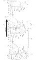
- the circular saw 10 As shown in FIG. 1, the circular saw 10 according to the embodiment is disposed on each of a base 12 formed in a substantially disc shape and a plurality of tooth bodies 14 formed on an outer peripheral portion of the base 12. Chip 30.
- the circular saw 10 is rotated in a predetermined direction with a virtual axis passing through the center of the base metal 12 in the thickness direction of the base metal 12 as a rotation center O.
- the workpiece is cut by pressing against the material.
- the base metal 12 is made of steel such as carbon tool steel or alloy tool steel, and each tooth body 14 is formed so as to protrude radially outward from the main body portion of the base metal 12.
- a plurality of tooth bodies 14 are formed on the outer peripheral portion of the base metal 12 so as to be spaced apart from each other in the rotation direction (circumferential direction) at uniform intervals or non-uniform intervals.
- a tooth bag 16 capable of accommodating a workpiece cutting waste generated when cutting with the chip 30 is formed on the front side in the rotation direction of each chip 30.
- the base metal 12 is provided with an installation portion 18 on the front side in the rotational direction of each tooth body 14.
- the installation portion 18 of the embodiment includes a vertical wall surface 18 a formed to extend in the radial direction corresponding to the back surface 34 facing the rear side in the rotation direction of the tip 30, and teeth corresponding to the base portion 31 of the tip 30. It is defined by a concave surface 18b formed so as to be recessed radially inward from the bottom 17.
- the plurality of tooth bodies 14 are formed in the same shape
- the plurality of chips 30 are formed in the same shape
- all the tooth bags 16 have the same shape. It has become.
- the chip 30 is a single block made of cemented carbide, cermet, CBN (cubic boron nitride), polycrystalline diamond, or the like, or a block-like material made of a composite material obtained by combining these. Further, the chip 30 may form a film on the outer surface.
- the coating may have a single layer structure or a multilayer structure in which the same or different ones are stacked, and a metal, nitride, carbide, one or more elements such as chromium, titanium, aluminum, etc. Mention may be made of layers of carbonitrides, oxides, oxynitrides and the like.
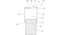
- the chip 30 has a back surface 34 bonded to the vertical wall surface 18a and a peripheral surface of the base 31 bonded to the concave surface 18b.
- the chip 30 has both side surfaces 36 and 36 facing in the width direction (the direction along the rotation axis of the circular saw 10) and a flank 38 formed on the outer peripheral surface facing outward in the radial direction exposed from the base metal 12.
- the surface facing the front side in the rotational direction excluding the peripheral surface of the base 31 fitted in the recess 18 b faces the tooth bag 16.
- the chip 30 is formed such that the dimension in the width direction is slightly larger than the thickness of the base metal 12.
- the chip 30 is formed such that each side surface 36 is a flat surface, and both side surfaces 36, 36 are separated from each other in the radial direction from the inner side toward the outer side.
- the tip 30 of the embodiment is wider on the cutting edge 32 side than on the base 31 side.
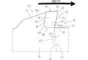
- the tip 30 has a cutting edge 32 at the edge of the flank 38 on the front side in the rotation direction, and a first rake face 40 facing the front side in the rotation direction is formed in contact with the cutting edge 32.
- the flank 38 tilts radially inward from the cutting edge 32 toward the rear side in the rotation direction with respect to a plane orthogonal to the virtual first reference line L1 connecting the rotation center O and the cutting edge 32 with a straight line.
- the cutting edge 32 has other shapes, such as a straight ridge as shown in FIG. 2 or a mountain shape that inclines radially inward from the center in the width direction toward the outside in the width direction. May be.
- the flank 38 may be provided with a nick 38a for dividing the cutting waste (see FIG.
- the nick 38a recessed inward in the radial direction is rotated in the direction of the flank 38. It is formed over the entire length and is disposed at a position deviating from the center in the width direction.
- the tip 30 of the embodiment is tapered by chamfering both corners in the width direction of the flank 38.
- the first rake face 40 is formed as a flat plane over the entire radial direction and width direction, and the first rake angle ⁇ 1 with respect to the first reference line L1 is set to be a negative angle. That is, the first rake face 40 is formed so as to incline forward in the rotational direction as it goes from the radially outer side to the inner side.
- the tip 30 is formed with a second rake face 42 facing the tooth bag 16 provided on the front side in the rotational direction of the tip 30 on the radially inner side of the first rake face 40.
- the second rake face 42 is in contact with the outer peripheral edge of the base 12 defining the tooth bag 16 at the inner edge in the radial direction, and in the embodiment, the inner edge is in contact with the tooth bottom 17 extending substantially along the rotation direction. ing. That is, the boundary P between the tip 30 appearing in the tooth bag 16 and the outer peripheral edge of the base metal 12 is formed at the intersection of the second rake face 42 and the tooth bottom 17. As shown in FIG.
- the second rake face 42 may be formed as a flat plane over the entire radial direction and width direction, or formed as a curved surface that is curved in the radial direction so that the tooth bag 16 side is concave or convex. You can also.
- the second rake face 42 is formed by the first reference line L1 and the second reference line L2, which is an imaginary line that passes straight through the inner edge of the second rake face 42 along the second rake face 42.
- the two rake angles ⁇ 2 are formed to be negative. That is, the second rake face 42 is inclined with respect to the first reference line L1 so as to incline toward the front side in the rotational direction from the radially outer side toward the inner side, and is formed so as not to be parallel to the first reference line L1. .
- the second rake face 42 is formed as a flat surface as in the embodiment, the second reference line L2 and the second rake face 42 coincide, and when the second rake face 42 is a curved surface, The 2 reference line L2 becomes a tangent line passing through the inner edge.
- the second rake face 42 is an angle ⁇ 3 formed by a virtual third reference line L3 that connects the rotation center O of the circular saw 10 and the inner edge of the second rake face 42 with a straight line and the second reference line L2. Is also formed to have a negative angle.
- the second rake face 42 is formed so that the inclination angle of the first rake face 40 is changed from that of the first rake face 40 so that the second rake angle ⁇ 2 is larger on the positive side than the first rake angle ⁇ 1.
- the second rake face 42 (second reference line L2) is formed so as to be inclined rearward (positive side) in the rotational direction with respect to the first rake face 40.
- the second rake face 42 is the first rake face. It is preferable to set the angle so as to incline toward the positive side in the range of 5 ° to 45 ° with respect to the surface 40.
- the 2nd rake face 42 of an Example is formed more largely than the 1st rake face 40 in the radial direction.
- the chip 30 is formed such that the back surface 34 is formed in parallel with the first reference line L1 as shown in FIG. 2, or is inclined forward in the rotational direction as it goes from the radially outer side to the inner side.
- the tip 30 may have the same width in the rotational direction between the second rake face 42 and the rear face 34 in the radial direction, but as shown in FIG. It is preferable to form so that it becomes wider as it goes to.
- the base 31 on the radially inner side extends radially inward from the inner edge of the second rake face 42.
- the tip 30 includes a dispersion surface 44 formed on the circumferential surface of the base portion 31 so as to be inclined to the rear side in the rotation direction with respect to the second reference line L ⁇ b> 2, being connected to the radially inner side of the inner edge of the second rake face 42.
- the dispersion surface 44 is formed so as to incline toward the rear side (positive side) in the rotational direction from the inner edge of the second rake face 42 toward the inner side in the radial direction and to have a positive inclination angle ⁇ 4 with respect to the first reference line L1.
- the dispersion surface 44 is also at a positive angle with respect to the second reference line L2.
- a bottom surface 46 extending so as to be orthogonal to the first reference line L ⁇ b> 1 is connected to the inner side in the radial direction of the dispersion surface 44, and an inclined surface 48 is formed between the back surface 34 and the bottom surface 46. Is done.
- the inclined surface 48 is inclined to the front side (negative side) in the rotational direction as it goes radially inward from the back surface 34, and is formed to have a negative angle with respect to the first reference line L1.
- the peripheral surface of the base portion 31 is formed in a shape in which corner portions before and after the rotation direction are chamfered, and the peripheral surface formed as a multifaceted surface is joined to the concave surface 18 b of the installation portion 18.
- the outer peripheral edge 14 a of the tooth body 14 is connected to the back surface 34 of the chip 30 disposed on the front side in the rotation direction, and the outer peripheral edge 14 a is the cutting edge 32 of the chip 30. It extends more radially inward.
- the outer peripheral edge 14a of the tooth body 14 is formed so as to incline radially outward from the tooth bag 16 side toward the front side in the rotational direction.
- a protrusion 20 is formed on the outer peripheral edge 14 a of the tooth body 14 so as to protrude radially outward from the outer peripheral edge 14 a, and the top of the protrusion 20 on the outer side in the radial direction is more radial than the cutting edge 32 of the tip 30.
- the protrusion 20 is provided on the front side in the rotation direction of the tooth bag 16 and is preferably formed so that the top is located within 1.5 mm inward in the radial direction from the rotation locus of the cutting edge 32 of the tip 30.
- the protrusion 20 of the embodiment protrudes from the outer peripheral edge of the tooth body 14 in a bump shape, and the top is formed in an arc shape. Further, the protrusion 20 is formed so that the edge on the front side in the rotation direction is inclined inward in the radial direction as it goes from the top to the front side in the rotation direction.
- the second rake face 42 is inclined at a negative angle with respect to the first reference line L1
- the impact when the cutting waste or the like hits the front surface in the rotational direction of the chip 30 is affected by the chip 30 and the base metal 12. It is possible to suppress concentration on the boundary P. Therefore, in the circular saw 10, the load on the boundary P between the chip 30 and the base metal 12 having relatively low strength can be suppressed, and the chip 30 breaks from the joint part of the boundary P due to the concentration of stress and the chip 30 is removed from the base metal 12. It is possible to prevent the chip 30 from dropping off or being damaged.
- the circular saw 10 can cut smoothly. Since the circular saw 10 is set to a negative angle in which the second rake face 42 is set to be more positive than the first rake face 40, the load on the boundary P between the chip 30 and the base metal 12 can be further suppressed. it can.
- the base portion 31 radially inward from the second rake face 42 of the chip 30 is fitted into the installation portion 18 of the base metal 12 that is recessed according to the base portion 31, so that not only the back surface 34 but also the base portion 31. Is also joined to the base 12. Since the circular saw 10 receives the cutting force applied to the chip 30 at the joint portion between the peripheral surface of the base portion 31 of the tip 30 and the concave surface 18b of the installation portion 18 of the base metal 12, the stress applied to the joint portion during cutting is reduced. Decrease. Further, according to the embodiment, when an impact is applied to the boundary P facing the tooth bag 16 between the second rake face 42 of the chip 30 and the base metal 12, the base bottom surface of the chip 30 is the second rake face 42.
- the peripheral surface of the base 31 is composed of multiple surfaces and the bonding surface of the base metal 12 is formed in accordance with the peripheral surface. Therefore, the bonding area between the chip 30 and the base metal 12 can be increased.
- the bonding strength of the chip 30 to the base metal 12 can be improved.
- the tip 30 is formed so that the width before and after the rotation direction between the second rake face 42 and the rear face 34 becomes wider from the outside in the radial direction toward the inside, so that the periphery of the base 31 joined to the base metal 12 is formed. Since the surface can be widened, the bonding strength of the chip 30 to the base metal 12 can be further improved.
- the circular saw 10 Since the circular saw 10 is provided with a protrusion 20 protruding radially outward on the outer peripheral edge 14a of the tooth body 14 extending to the front side in the rotation direction of the tooth bag 16, the tooth bag is cut by the protrusion 20 during cutting. It is possible to make it difficult for the cutting scraps to be caught in 16. Therefore, the circular saw 10 can suppress the entanglement of the cutting waste into the tooth bag 16 which is one of the factors of the load on the chip 30 by the protrusion 20, so that the chip 30 is damaged or the table near the chip 30. It is possible to prevent the so-called neck breakage in which the gold 12 is broken and broken.
- a test for actually cutting a workpiece was performed on the circular saw 10 of the embodiment shown in FIGS. 1 to 3 and the circular saw 50 of the comparative example shown in FIG. 4, and the two were compared.
- a carbon steel pipe for mechanical structure STKM13A
- the workpiece has an outer diameter of 50.8 mm and a thickness of 5 mm.
- the circular saws 10 and 50 of the examples and comparative examples use a base metal 12 having a thickness of 1.7 mm, an outer diameter of 285 mm, the number of teeth is set to 80, and a cutting edge width of 2 mm. 52 is brazed to the base 12.
- the chips 30 and 52 of Examples and Comparative Examples are cemented carbides having a TiAlN-based film formed on the outer surface.
- the first rake face 40 has a radial width of 0.3 mm
- the second rake faces 42 and 54 have the same radial width.
- the first rake angle ⁇ 1 of the first rake face 40 is ⁇ 25 °
- the second rake angle ⁇ 2 of the second rake face 42 is ⁇ 5 °
- the inclination angle ⁇ 4 of the dispersion surface 44 is 45.
- the back surface 34 is formed in parallel with the first reference line L1.
- the protrusion 20 is formed on the front side in the rotation direction of the tooth bag 16, whereas the circular saw 50 of the comparative example extends on the front side in the rotation direction of the tooth bag 16.
- the outer peripheral edge 14 a of the tooth body 14 is not provided with a shape corresponding to the protrusion 20.
- the first rake face ⁇ 1 of the first rake face 40 is set to ⁇ 25 °
- the second rake angle ⁇ 2 of the second rake face 52 is set to 10 °
- the back face 56 is set to the second rake face 52. Extends in parallel with.
- the chip 52 of the comparative example is formed so that the bottom surface 58 extends along the rotation direction from the boundary P between the second rake face 42 and the base metal 12, and the base 31 is fitted into the base metal 12 as in the embodiment.
- the workpiece was cut while supplying mist at a cutting speed of 358 m / min and a feed amount per tooth of 0.07 mm.
- Two round saws 10 and 50 of the example and the comparative example were prepared for the test, and each test was performed twice. The results are shown in Table 1.
- the circular saw 50 of the comparative example has a lot of biting until it reaches the total number of cuts until it becomes impossible to continue cutting due to abnormalities of the tip 52 such as neck breakage, chipping or chipping. .
- the circular saw 10 of the embodiment can continue the cutting even when the total number of cuts shown in Table 1 is reached, so that the cutting can be continued and more than the comparative example.
- the circular saw 10 of the example hardly bites and the chip 30 is not easily damaged.
- the analysis models 1 to 4 of the circular saw according to the present invention and the analysis model 5 according to the comparative example are created by the finite element method, and the tooth bag 16 is obtained for each of the analysis models 1 to 5.
- the analysis model 1 shown in FIG. 5 (a) is set to the same conditions as the embodiment described in the paragraph [0026] except that the width of the cutting edge 32 of 3 mm and the inclined surface 48 are not present.
- the analysis model 2 shown in FIG. 5B is an analysis model except that the second rake face 42 is extended in the radial direction as it is and the base 31 is fitted into the base metal 12, and the dispersion surface 44 is not provided.
- the analysis model 3 shown in FIG. 5C is a chip 30 having the same shape as the analysis model 2 and is different from the analysis model 2 in that the base 31 of the chip 30 is not fitted into the base metal.
- the analysis model 4 shown in FIG. 5D is obtained by forming a bottom surface 46 along the rotational direction from the second rake face 42 of the analysis model 1, and the base portion is not fitted into the base metal 12.
- the analysis model 5 shown in FIG. 5 (e) is set to the same conditions as the comparative example described in paragraph [0026] except that the width of the cutting edge 32 of 3 mm and the inclined surface 48 are not present.
- analysis model 1 is 15.3 kgf / mm 2
- analysis model 2 is 16.6 kgf / mm 2
- analysis model 3 is 17.3 kgf / mm 2
- analysis model 4 is 16.8 kgf / mm 2.
- mm 2 and analysis model 5 was 22.5 kgf / mm 2 .
- the main stress applied to the boundary P between the second rake face 42 and the base metal 12 is reduced by setting the second rake face 42 of the chip 30 as in the present invention. Further, by fitting the base portion 31 of the chip 30 to the base metal 12, the main stress of the boundary P becomes lower, and by forming the dispersion surface 44 on the base portion 31 fitted to the base metal 12, the boundary boundary is further increased. It can be seen that the main stress of P is lowered.
- the present invention is not limited to the above-described configuration, and can be modified as follows, for example.
- the chip may form an auxiliary rake face between the first rake face and the second rake face.
- the auxiliary rake face is formed so as to incline forward in the rotational direction from the outer side in the radial direction toward the first reference line, and the auxiliary rake angle made with the first reference line is set to a negative angle. , May be parallel to the first reference line.
- the auxiliary rake face may be formed so as to incline toward the rear side in the rotational direction from the outer side in the radial direction toward the inner side with respect to the first reference line, and the auxiliary rake angle may be a positive angle.
- the auxiliary rake face preferably has a negative rake angle.
- the auxiliary rake angle is set to a negative angle inclined to the positive side from the first rake angle
- the second rake angle may be set as a negative angle inclined to the positive side of the auxiliary rake face (
- the tip is not limited to the configuration in which the base is fitted into the base metal, but may have a shape in which the bottom surface extends along the rotational direction through the boundary facing the tooth bag between the second rake face and the base metal. Good.
- the shape of the protrusion is not limited to the circular arc shape in a side view, and may be a triangular shape, a rectangular shape, or other shapes.
Landscapes
- Engineering & Computer Science (AREA)
- Mechanical Engineering (AREA)
- Drilling Tools (AREA)
- Cutting Tools, Boring Holders, And Turrets (AREA)
- Harvester Elements (AREA)
- Processing Of Stones Or Stones Resemblance Materials (AREA)
- Milling Processes (AREA)
Priority Applications (3)
| Application Number | Priority Date | Filing Date | Title |
|---|---|---|---|
| CN201480010372.0A CN105008077B (zh) | 2013-02-25 | 2014-01-30 | 圆锯 |
| EP14754288.0A EP2949414B2 (en) | 2013-02-25 | 2014-01-30 | Circular saw blade |
| US14/767,204 US20160001383A1 (en) | 2013-02-25 | 2014-01-30 | Circular saw blade |
Applications Claiming Priority (2)
| Application Number | Priority Date | Filing Date | Title |
|---|---|---|---|
| JP2013034207A JP6339764B2 (ja) | 2013-02-25 | 2013-02-25 | 丸鋸 |
| JP2013-034207 | 2013-02-25 |
Publications (1)
| Publication Number | Publication Date |
|---|---|
| WO2014129285A1 true WO2014129285A1 (ja) | 2014-08-28 |
Family
ID=51391081
Family Applications (1)
| Application Number | Title | Priority Date | Filing Date |
|---|---|---|---|
| PCT/JP2014/052160 Ceased WO2014129285A1 (ja) | 2013-02-25 | 2014-01-30 | 丸鋸 |
Country Status (5)
| Country | Link |
|---|---|
| US (1) | US20160001383A1 (enExample) |
| EP (1) | EP2949414B2 (enExample) |
| JP (1) | JP6339764B2 (enExample) |
| CN (1) | CN105008077B (enExample) |
| WO (1) | WO2014129285A1 (enExample) |
Cited By (1)
| Publication number | Priority date | Publication date | Assignee | Title |
|---|---|---|---|---|
| EP3263259B1 (en) * | 2016-06-30 | 2023-07-12 | Tanitec Corporation | Tip saw for composite material |
Families Citing this family (8)
| Publication number | Priority date | Publication date | Assignee | Title |
|---|---|---|---|---|
| WO2018074038A1 (ja) | 2016-10-18 | 2018-04-26 | 兼房株式会社 | チップ付き丸鋸刃 |
| CN117021258A (zh) * | 2018-09-07 | 2023-11-10 | 大连金河精密工具有限公司 | 单片式开槽刀 |
| PL129948U1 (pl) * | 2018-12-14 | 2023-11-13 | Politechnika Lubelska | Piła z łamaczami wiórów |
| EP4079433A4 (en) * | 2019-12-19 | 2024-01-17 | Kanefusa Kabushiki Kaisha | POINTED SAW |
| JPWO2021171945A1 (enExample) | 2020-02-28 | 2021-09-02 | ||
| KR102148275B1 (ko) * | 2020-02-29 | 2020-08-26 | 곽기웅 | 칩배출부재를 갖는 원형톱 |
| DE102020128920A1 (de) * | 2020-11-03 | 2022-05-05 | WIKUS-Sägenfabrik Wilhelm H. Kullmann GmbH & Co. KG | Superlegierungssägeblatt |
| NO347919B1 (en) | 2023-05-03 | 2024-05-13 | Ra Jacobsen Kenneth | System providing increased cutting accuracy of fibre insulation batts |
Citations (5)
| Publication number | Priority date | Publication date | Assignee | Title |
|---|---|---|---|---|
| JPH07116916A (ja) | 1993-10-25 | 1995-05-09 | Shinkoonan:Kk | ろう付けホットソー及びその製造方法 |
| JPH09216121A (ja) * | 1996-02-14 | 1997-08-19 | Tsune Wagner Carbide:Kk | 丸 鋸 |
| JP2009119869A (ja) * | 2007-11-15 | 2009-06-04 | Wikus Saegenfabrik Wilhelm H Kullmann Gmbh & Co Kg | 石鋸刃 |
| JP2009292142A (ja) * | 2008-12-08 | 2009-12-17 | Ryobi Ltd | 切断機の複合鋸刃 |
| JP2011168035A (ja) * | 2010-02-17 | 2011-09-01 | Trigger:Kk | チップソー及びその製造方法 |
Family Cites Families (20)
| Publication number | Priority date | Publication date | Assignee | Title |
|---|---|---|---|---|
| GB191321297A (en) * | 1913-09-20 | 1914-04-02 | Elmer Ellsworth Smith | Improvements in Milling Cutters, Circular Saws and like Cutting Devices. |
| DE1957024A1 (de) * | 1969-11-13 | 1971-05-27 | Albert Knebel | Kreissaegeblatt zur Metallbearbeitung mit Zaehnen mit eingesetzten Hartmetallkoerpern |
| US4463645A (en) * | 1983-02-22 | 1984-08-07 | Speedcut, Inc. | Circular saw |
| US4604933A (en) * | 1983-10-28 | 1986-08-12 | North American Products Corp. | Carbide-tipped circular saw for metal cutting at low surface speeds |
| US4784033A (en) * | 1986-01-22 | 1988-11-15 | Milford Products Corporation | Triple chip ground carbide tip bandsaw blade with ductile filler |
| DE3711228A1 (de) * | 1987-04-03 | 1988-10-20 | Wagner Maschf Gustav | Schneidezahn sowie mit solchen schneidezaehnen versehene metallsaegen, insbesondere kreissaegeblaetter |
| DE3943321A1 (de) * | 1988-12-29 | 1990-07-05 | Ryobi Ltd | Schneideinsaetze fuer kreissaegeblaetter |
| JP3170498B2 (ja) * | 1999-01-29 | 2001-05-28 | 兼房株式会社 | 丸 鋸 |
| US20030233927A1 (en) * | 2002-06-19 | 2003-12-25 | Johnson David N. | Circular saw blade for cutting ferrous materials |
| JP2005059124A (ja) * | 2003-08-08 | 2005-03-10 | Tenryu Saw Mfg Co Ltd | 回転鋸 |
| JP2006289558A (ja) * | 2005-04-12 | 2006-10-26 | Tenryu Saw Mfg Co Ltd | ディスクカッター |
| CN100406177C (zh) * | 2005-11-02 | 2008-07-30 | 天龙制锯株式会社 | 旋转锯 |
| JP4853958B2 (ja) * | 2006-06-28 | 2012-01-11 | 株式会社谷テック | チップソー |
| DE102007022001B4 (de) * | 2007-05-08 | 2011-06-30 | Leitz GmbH & Co. KG, 73447 | Werkzeug zur spanabhebenden Bearbeitung, insbesondere Kreissägeblatt |
| DE102007054600B4 (de) * | 2007-11-15 | 2013-07-25 | WIKUS-Sägenfabrik Wilhelm H. Kullmann GmbH & Co. KG | Sägeblatt mit einem Grundkörper und Zähnen mit Schneiden |
| DE102009027896B4 (de) | 2009-07-21 | 2011-09-22 | WIKUS-Sägenfabrik Wilhelm H. Kullmann GmbH & Co. KG | Sägeblatt mit Zähnen mit einem Spanumformelement |
| JP5600029B2 (ja) * | 2010-04-19 | 2014-10-01 | アクトテック株式会社 | 回転鋸 |
| US8695465B2 (en) * | 2010-08-18 | 2014-04-15 | Advanced Machine & Engineering Co. | Saw blade stabilizer and method |
| CN202367276U (zh) * | 2011-12-23 | 2012-08-08 | 佛山市南海日东工具制造有限公司 | 抗变形耐切割不掉齿的新型切铁锯片 |
| WO2013098963A1 (ja) * | 2011-12-27 | 2013-07-04 | 株式会社谷テック | 金属切断用チップソー |
-
2013
- 2013-02-25 JP JP2013034207A patent/JP6339764B2/ja active Active
-
2014
- 2014-01-30 EP EP14754288.0A patent/EP2949414B2/en active Active
- 2014-01-30 US US14/767,204 patent/US20160001383A1/en not_active Abandoned
- 2014-01-30 CN CN201480010372.0A patent/CN105008077B/zh active Active
- 2014-01-30 WO PCT/JP2014/052160 patent/WO2014129285A1/ja not_active Ceased
Patent Citations (5)
| Publication number | Priority date | Publication date | Assignee | Title |
|---|---|---|---|---|
| JPH07116916A (ja) | 1993-10-25 | 1995-05-09 | Shinkoonan:Kk | ろう付けホットソー及びその製造方法 |
| JPH09216121A (ja) * | 1996-02-14 | 1997-08-19 | Tsune Wagner Carbide:Kk | 丸 鋸 |
| JP2009119869A (ja) * | 2007-11-15 | 2009-06-04 | Wikus Saegenfabrik Wilhelm H Kullmann Gmbh & Co Kg | 石鋸刃 |
| JP2009292142A (ja) * | 2008-12-08 | 2009-12-17 | Ryobi Ltd | 切断機の複合鋸刃 |
| JP2011168035A (ja) * | 2010-02-17 | 2011-09-01 | Trigger:Kk | チップソー及びその製造方法 |
Cited By (1)
| Publication number | Priority date | Publication date | Assignee | Title |
|---|---|---|---|---|
| EP3263259B1 (en) * | 2016-06-30 | 2023-07-12 | Tanitec Corporation | Tip saw for composite material |
Also Published As
| Publication number | Publication date |
|---|---|
| JP2014161942A (ja) | 2014-09-08 |
| CN105008077B (zh) | 2018-04-24 |
| CN105008077A (zh) | 2015-10-28 |
| EP2949414A1 (en) | 2015-12-02 |
| EP2949414A4 (en) | 2016-11-02 |
| JP6339764B2 (ja) | 2018-06-06 |
| US20160001383A1 (en) | 2016-01-07 |
| EP2949414B1 (en) | 2017-12-20 |
| EP2949414B2 (en) | 2020-10-28 |
Similar Documents
| Publication | Publication Date | Title |
|---|---|---|
| JP6339764B2 (ja) | 丸鋸 | |
| US20070172321A1 (en) | Ball endmill | |
| CN111867762B (zh) | 刀片和包括刀片的切削工具组件 | |
| US3973455A (en) | Saw | |
| JP2008264979A (ja) | 穿孔用回転切削工具 | |
| WO2015098360A1 (ja) | カッター | |
| WO2014157135A1 (ja) | ドリル用インサートおよび刃先交換式ドリル | |
| JP2017080864A (ja) | 刃先交換式リーマおよびリーマ用インサート | |
| JP4957000B2 (ja) | 切削工具 | |
| US6321618B1 (en) | Cutting tip having rounded main cutting edge and sharp side cutting edges | |
| JP5300665B2 (ja) | チップソーの製造方法 | |
| JP6577293B2 (ja) | チップ付き丸鋸刃 | |
| JP4142892B2 (ja) | 刃先交換式回転工具 | |
| JP2011101928A (ja) | 鑞付けドリル | |
| JP5441224B2 (ja) | 突切りバイト | |
| JP2008142834A (ja) | ドリル | |
| JP4359221B2 (ja) | 非鉄金属加工用チップの作製方法 | |
| JPH039945Y2 (enExample) | ||
| JP2015166119A (ja) | エンドミル | |
| WO2013015404A1 (ja) | 刃先交換式回転切削工具およびこれに用いる切削インサート | |
| JP4702804B2 (ja) | 金属切断用丸鋸 | |
| JP4752324B2 (ja) | ピンミラーカッター | |
| JP2001079803A (ja) | チップソー | |
| JP4146763B2 (ja) | 金属切断用丸鋸 | |
| JP2003019618A (ja) | ボールエンドミル |
Legal Events
| Date | Code | Title | Description |
|---|---|---|---|
| 121 | Ep: the epo has been informed by wipo that ep was designated in this application |
Ref document number: 14754288 Country of ref document: EP Kind code of ref document: A1 |
|
| WWE | Wipo information: entry into national phase |
Ref document number: 14767204 Country of ref document: US |
|
| NENP | Non-entry into the national phase |
Ref country code: DE |
|
| WWE | Wipo information: entry into national phase |
Ref document number: 2014754288 Country of ref document: EP |