WO2013015404A1 - 刃先交換式回転切削工具およびこれに用いる切削インサート - Google Patents
刃先交換式回転切削工具およびこれに用いる切削インサート Download PDFInfo
- Publication number
- WO2013015404A1 WO2013015404A1 PCT/JP2012/069107 JP2012069107W WO2013015404A1 WO 2013015404 A1 WO2013015404 A1 WO 2013015404A1 JP 2012069107 W JP2012069107 W JP 2012069107W WO 2013015404 A1 WO2013015404 A1 WO 2013015404A1
- Authority
- WO
- WIPO (PCT)
- Prior art keywords
- cutting
- blade
- rake face
- flank
- cutting insert
- Prior art date
Links
Images


Classifications
-
- B—PERFORMING OPERATIONS; TRANSPORTING
- B23—MACHINE TOOLS; METAL-WORKING NOT OTHERWISE PROVIDED FOR
- B23B—TURNING; BORING
- B23B27/00—Tools for turning or boring machines; Tools of a similar kind in general; Accessories therefor
- B23B27/14—Cutting tools of which the bits or tips or cutting inserts are of special material
- B23B27/141—Specially shaped plate-like cutting inserts, i.e. length greater or equal to width, width greater than or equal to thickness
- B23B27/145—Specially shaped plate-like cutting inserts, i.e. length greater or equal to width, width greater than or equal to thickness characterised by having a special shape
-
- B—PERFORMING OPERATIONS; TRANSPORTING
- B23—MACHINE TOOLS; METAL-WORKING NOT OTHERWISE PROVIDED FOR
- B23B—TURNING; BORING
- B23B51/00—Tools for drilling machines
-
- B—PERFORMING OPERATIONS; TRANSPORTING
- B23—MACHINE TOOLS; METAL-WORKING NOT OTHERWISE PROVIDED FOR
- B23B—TURNING; BORING
- B23B2200/00—Details of cutting inserts
- B23B2200/08—Rake or top surfaces
- B23B2200/085—Rake or top surfaces discontinuous
-
- B—PERFORMING OPERATIONS; TRANSPORTING
- B23—MACHINE TOOLS; METAL-WORKING NOT OTHERWISE PROVIDED FOR
- B23B—TURNING; BORING
- B23B2200/00—Details of cutting inserts
- B23B2200/16—Supporting or bottom surfaces
- B23B2200/163—Supporting or bottom surfaces discontinuous
Definitions
- the present invention relates to a cutting tool exchangeable rotary cutting including a tool body rotatable around a rotation axis, and two cutting inserts each having a main cutting edge and detachably disposed in a tip region of the tool body.
- the present invention relates to a tool and a cutting insert used for the tool.
- a blade-tip replaceable drill disclosed in Patent Document 1 includes a main body that can rotate around a rotation axis, two chip seats disposed in a tip region of the main body, and a drill tool that is replaceably attached to the chip seat. Two cutting inserts that are opposed to each other across the axis and that form a gap in the center.
- the above two cutting inserts each have an outer peripheral cutting edge (hereinafter referred to as an outer cutting edge) and a central cutting edge portion (hereinafter referred to as an inner cutting edge) following this, and have an inner axis across the rotation axis. It arrange
- the drill diameter of the blade-tip-exchangeable drill to which this cutting insert can be applied is determined by the length of the cutting edge from the outer peripheral side to the end portion of the inner blade. In other words, it is difficult to use the same cutting insert in common for tool bodies having a low degree of freedom in arrangement and slightly different drill diameters.
- the drill diameter can be slightly adjusted.
- the inner blade portions overlap each other, there is a problem that chips are easily clogged in a narrow gap formed between the overlapping portions of the inner blades. For this reason, the adjustment range of the drill diameter is actually limited.
- the present invention can be used in common for rotary cutting tools of various drill diameters, and can also prevent clogging of chips between two or more cutting inserts, and a cutting insert used therefor. I will provide a.
- the cutting edge exchange-type rotary cutting tool of the present invention includes a tool body (10) that can rotate about a rotation axis (C), and a cutting insert (50) that is detachably attached to a tip region of the tool body (10).
- a plurality of cutting inserts (50) are arranged at rotationally symmetric positions with respect to the rotation axis (C), and each of the plurality of cutting inserts (50) includes: An outer blade (51) extending from the rotation axis side to the outer peripheral side, and an inner blade (52) connected to the outer blade (51) and disposed on the rotation axis (C) side, When viewed from the front end side of the tool body (10), at least one of the inner blades (52) of the plurality of cutting inserts (50) is curved convexly with respect to the rotation axis (C).
- the cutting insert of the present invention is detachably disposed at a plurality of positions around the rotation axis (C) in the tip region of the tool body (10) rotatable around the rotation axis (C).
- the cutting insert (50) is formed in a plate shape, and a cutting edge is formed on an intersecting ridge line between at least one of the upper surface or the lower surface and the outer peripheral side surface, and the cutting blade includes an outer blade (51) and an outer edge.
- the first rake face that is formed so as to protrude from the second abutment surface (83), is inclined with respect to the second abutment surface (83), and is connected to the outer blade (51) (61) and the second rake connected to the first rake face (61), inclined in a direction different from the first rake face (61) and connected to the inner blade (52).
- the inner blade (52) is convexly curved.
- the amount of overlapping of the inner blades can be easily adjusted in a state where two or more inner blades face each other with the rotation axis interposed therebetween. Therefore, the degree of freedom of arrangement of the cutting insert is high. For this reason, it becomes possible to deal with tools having various drill diameters. Further, according to the present invention, since at least one inner blade of the two or more cutting inserts is convexly curved with respect to the rotation axis, chips formed at the center of the tool are laterally moved. It becomes easy to escape and can suppress clogging between cutting inserts.
- FIG. 7 is a cross-sectional view taken along a plane A that includes the axis AX of the cutting insert of FIG.
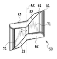
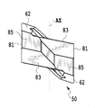
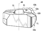
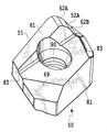
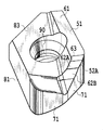
- the perspective view from one direction of the cutting insert of FIG. The perspective view from the other direction of the cutting insert of FIG.
- the side view of the tool main body seen from the direction along the Y plane of FIG. The side view of the tool main body seen from the direction along X plane of FIG.
- the perspective view from the other direction of the tool main body of FIG. It is a front view which shows the 1st modification of the 1st Embodiment of this invention.
- FIG. 1 It is a front view which shows the 1st modification of the 1st Embodiment of this invention. It is a front view which shows the 2nd modification of the 1st Embodiment of this invention. It is a front view of the cutting insert used for the cutting tool of FIG.
- the front view of the cutting insert which concerns on the 2nd Embodiment of this invention.
- the bottom view of the cutting insert of FIG. The rear view of the cutting insert of FIG.
- the right view of the cutting insert of FIG. It is a perspective view of the bottom face side of the cutting insert of FIG. It is a perspective view from the other direction of the bottom face side of the cutting insert of FIG.
- the blade-tip-exchange-type rotary cutting tool is a rotary cutting tool capable of drilling, and is used as a drill, for example.
- “Perforating” means that cutting can be performed in a direction parallel to the rotation axis C of the rotary tool. That is, a cutting edge is required from the outer periphery to the vicinity of the rotation axis C at the tip portion of the rotary cutting tool.
- the cutting edge exchange type rotary cutting tool includes a tool main body 10 that can rotate around a rotation axis C extending in the longitudinal direction, and a rotational symmetry about the rotation axis C at a tip region of the tool main body 10 by approximately 180 degrees.
- the two cutting inserts 50 are negative type cutting inserts having the same shape.
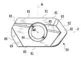
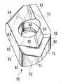
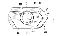
- the cutting insert 50 is formed in a plate shape and has first to third contact surfaces 81, 83 and 85. These three surfaces are in contact with first to third seat surfaces 21, 23, and 25 of the tool body 10, which will be described later.
- the first contact surface 81 is formed on the outer peripheral side surface of the cutting insert 50, and is two flat surfaces parallel to each other.
- the second contact surfaces 83 are formed on the upper surface and the lower surface of the cutting insert 50, respectively, and are parallel to each other.
- the third contact surface 85 is a surface formed at two locations on the outer peripheral side surface of the cutting insert 50.
- first to third contact surfaces 81, 83, 85 are not limited to flat surfaces, and may be curved surfaces in other embodiments. In other words, any surface may be used as long as it is in contact with the first to third seat surfaces 21, 23, 25 formed on the tool body 10.
- the cutting insert 50 includes a through hole 90 for attaching the cutting insert.
- the through hole 90 is formed so as to penetrate the upper and lower surfaces, and has a central axis AX parallel to the first contact surface 81.
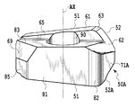
- a first rake face 61 is formed on the upper and lower surfaces of the cutting insert 50.
- the first rake face 61 is formed so as to protrude from the second contact surface 83, and is inclined with respect to the second contact surface 83. Specifically, as shown in FIG. 5, the first rake face 61 is inclined in a direction away from the cutting insert 50 from the left end side to the right end side of the cutting insert 50.
- the second rake face 62 is connected to a connection region 63 that is the most protruding portion of the first rake face 61, and is inclined with respect to the second abutting face 83 in a direction different from the first rake face 61. ing. Specifically, the second rake face 62 is inclined toward the bottom surface side of the cutting insert 50 as the distance from the connection region 63 increases. A part of the second rake face 62 intersects with the second contact face 83.
- connection region 63 When the first rake face 61 and the second rake face 62 are connected via the connection region 63, the shape of the cutting edge changes smoothly and the cutting insert becomes difficult to chip.
- the connection region 63 is not provided, and the first rake face 61 and the second rake face 62 may be directly connected. However, if the first rake face and the second rake face are directly connected, the ridgeline becomes a corner, which tends to cause the cutting insert to be chipped.
- the second rake face 83 is inclined.
- An inclined surface 65 is interposed.
- notched inclined surface portions 69 are formed on the upper and lower surfaces of the cutting insert 50 in order to prevent a part of the cutting insert 50 from projecting from the outer periphery of the tool body 10 and interfering with the workpiece after processing. Has been.
- the first contact surface 81 intersects with the first rake surface 61 and becomes a flank (first flank) of the outer blade 51 described later.
- the first contact surface 81 is smoothly connected to a connection surface 82 that is curved outward of the cutting insert 50, and the connection surface 82 is connected to a second flank 71 that intersects the second rake surface 62. It is connected.
- the outer blade 51 that cuts the outer peripheral side during drilling and the inner blade 52 that cuts the central side are the outer peripheral surfaces connecting the first contact surface 81, the connection surface 82, and the second flank 71. And the first rake face 61, the rake face connection region 63, and the rake face connecting the second rake face 62.
- the outer blade 51 is a part of the intersecting ridge line portion between the first contact surface 81 and the first rake surface 61 and the intersecting ridge line portion between the connection surface 82 and the first rake surface 61.
- the part which is comprised and is extended substantially linearly from the outer peripheral side of the tool main body 10 corresponds.
- the inner blade 52 is constituted by a part of the intersecting ridge line portion between the connection surface 82 and the first rake face 61 and the intersecting ridge line portion between the second flank 71 and the second rake face 62.
- the part extending in a different direction corresponds to this. That is, the inner blade 52 corresponds to a portion extending from the side where the outer blade 51 is disposed to the X plane and the Y plane, crossing the X plane and the Y plane shown in FIG.
- the portion extending linearly from the right (left) outer periphery of the tool body 10 toward the rotation axis C is the outer blade 51, and the rotation axis is bent from the outer blade 51.
- the portion that passes in the vicinity of C is the inner blade 52.
- the X plane is defined as a plane that includes the rotation axis C and passes through the outermost end of any one of the outer blades 51 as a reference.
- the Y plane is defined as a plane that includes the rotation axis C and is orthogonal to the X plane.
- the cutting insert 50 is 180-degree rotationally symmetric with respect to an axis of symmetry J that is orthogonal to the central axis AX and parallel to the first contact surface 81. Therefore, the cutting insert 50 can be used twice upside down.
- the inner blade 52 which is an intersection of the second rake face 62 and the second flank 71, as viewed from the direction of the symmetry axis J, is directed toward the rotational axis C. Curved in a convex shape.
- the inner blade 52 is curved in a convex shape when viewed from the direction facing the second flank 71. As will be described later, this is a configuration for suppressing the clogging of chips into a narrow gap formed between the overlapping portions of the inner blades.
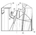
- the tool body 10 has two protrusions 11 at positions where its tip is 180 degrees rotationally symmetric with respect to the rotation axis C.
- the protrusion 11 is formed by cutting out the tip of the tool body 10 along the shape of the cutting insert 50.
- the two projecting portions 11 are formed with a first seat surface 21 with which the first abutting surface 81 of each cutting insert 50 abuts, and a screw hole penetrating the first seat surface 21. 40 is formed.
- the first seat surfaces 21 face each other across the rotation axis C and are parallel to the rotation axis C.
- the surface extending between the two protrusions 11 is a second seat surface 23 formed of an inclined surface (plane) that is rotationally symmetrical by 180 degrees with respect to the rotation axis C.
- the second seating surface 23 is inclined toward the rear end side of the tool body 10 as it goes radially outward from the rotation axis C side.
- the angle formed by the plane including the first seating surface 21 and the plane including the second seating surface 23 corresponding thereto is an acute angle.
- the third seating surface 25 is formed in the vicinity of the second seating surface 23 and is a flat surface inclined so as to face the second seating surface 23 side.
- the wall portion 26 that constitutes the third seating surface 25 and faces the outer peripheral direction of the tool main body 10 functions to protect the outer blade 51.
- a recess 30 having a concave curved surface extending along the first seat surface 21 is formed between the plane including the first seat surface 21 and the corresponding second seat surface 23.
- This recessed part 30 is for covering and protecting the one of the two cutting edges of the cutting insert 50 that is not used for cutting. By covering at least the outer blade 51 with the concave portion 30, it is possible to prevent the cutting blade that is not used during the cutting process from being damaged.
- the recess 30 is formed as a groove shape.
- the recessed part 30 can also be made into the shape which covers the whole cutting blade which is not used during cutting.
- two helical chip conveying grooves 15 are formed in the longitudinal direction on the outer peripheral surface of the tool body 10.
- the chip conveying groove 15 is continuous with a concave curved surface 24 adjacent to the second seat surface 23 shown in FIG. As shown in FIG. 13, the curved surface 24 is located immediately below the inner blade 52 in a direction parallel to the rotation axis C. By this curved surface 24, chips generated by the inner blade 52 are smoothly guided to the chip conveying groove 15.
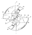
- the inner blades 52 of the two cutting inserts 50 are arranged so as to face each other across the rotation axis C when viewed from the tip, and are convex so that the tops of both inner blades 52 face the rotation axis C. It is curved. That is, when viewed from the tip, the two inner blades 51 are arranged at positions that are approximately 180 degrees rotationally symmetric with respect to the rotation axis C, and the interval GP1 between the inner blades 51 gradually increases as the distance from the rotation axis C increases in the radial direction. Has expanded to. Since the inner blades 52 of the two cutting inserts 50 face each other, a cylindrical non-cutting portion is formed between the two inner blades 52 during the cutting process.
- the interval GP2 between the second rake faces 62 that form the inner blades 52 of the two cutting inserts and that face each other is parallel to the rotation axis C. Is gradually enlarged toward the tool body 10 side. That is, the gap GP2 becomes wider from the front end side (upper drawing) of the tool main body 10 toward the rear end side (lower drawing) of the tool main body 10.
- the D direction is a direction along a plane passing through the rotation axis C between the second rake faces 62 facing each other and between the inner blades 52 facing each other.
- the “D direction” defined as described above is not limited to one, but the interval GP2 gradually increases toward the tool body 10 when viewed from all the directions defined as described above. It is formed to do.
- the two second flank surfaces 71 respectively forming the inner blades 52 of the two cutting inserts 50 are directed toward the rear end side of the tool body 10 toward the rear in the rotational direction of the rotary cutting tool. Inclined, and further toward the rear end side of the tool body 10 as it approaches the rotation axis C side.
- the gap GP1 is set as described above. Since it expands gradually as it leaves
- the two second flank surfaces 71 are inclined toward the rear end side of the tool body 10 as approaching the rotation axis C side, so It dents to the rear end side and does not interfere with the hole bottom.
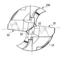
- FIGS. 17A and 17B are a first modification of the first embodiment.
- the tools shown in FIGS. 17A and 17B are obtained by attaching common cutting inserts to different tool bodies 10A and 10B.
- the same reference numerals are used for the same components as those in the first embodiment.
- the tool diameter of the tool body 10B shown in FIG. 17B is larger than the tool diameter of the tool body 10A shown in FIG. 17A. That is, since the cutting insert 50 according to the present embodiment places the two inner blades 52 facing each other across the rotation axis C, the cutting of the outer blade 51 is performed within a range where the inner blades 52 face each other across the rotation axis C. You can change the maximum diameter possible.
- the inner blade 52 is curved in a convex shape, the range in which the two inner blades 52 can be opposed to each other with the rotation axis C interposed therebetween is greater than the case where the inner blade is linear. Is also wide.
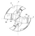
- FIGS. 18 and 19 show a second modification of the first embodiment.
- the same reference numerals are used for the same components as those in the first embodiment.
- the chip splitter 100 is formed on the first contact surface 81 of each cutting insert 50B.
- the chip splitter 100 is also called a nickname.
- the chip splitter 100 is a concave groove formed in the first contact surface 81 and extends in the thickness direction of the cutting insert 50.
- the formation position of one chip splitter 100 and the formation position of the other chip splitter 100 are not 180-degree rotationally symmetric with respect to the symmetry axis J.
- the difference between the second embodiment and the first embodiment is the shape of the cutting insert.
- the two inner blades 52 and 52A of the cutting insert 50A according to the present embodiment have different shapes and are asymmetric with respect to the above-described symmetry axis J.
- the second rake face 62 having the same shape as that of the first embodiment is formed on the upper surface, and the shape of the second rake face 62 is formed on the lower surface.
- a different third rake face 62A is formed.
- the third rake face 62A is connected in the connection region 63 of the first rake face 61, and is inclined in a direction different from that of the first rake face 61 and curved in a concave shape.
- a fourth rake face 62B is formed adjacent to the third rake face 62A, which is a flat surface.
- a second flank 71 intersecting with the second rake face 62 and a third flank 71A having a different shape from the second flank 71 intersecting with the third rake face 62A are formed on the side surfaces.
- the 1st inner blade 52 of the same shape as the inner blade of 1st Embodiment is formed in the intersection of the 2nd rake face 62 and the 2nd flank 71, and the 3rd rake face 62A and A second inner blade 52A having a shape different from that of the first inner blade 52 is formed at the intersection with the third flank 71A and at the intersection between the fourth rake face 62B and the third flank 71A. ing.
- the first inner blade 52 is curved in a convex shape toward the rotation axis C as seen from the direction of the symmetry axis J.
- the inner blade 52A is formed of a concavely curved portion and a linear portion when viewed from the direction of the symmetry axis J. That is, by making the shape of the third rake face 62A different from the shape of the fourth rake face 62B, the second inner blade 52A is formed by a curve curved in a concave shape with respect to the straight line and the rotation axis C. .
- the shortest distance from the second inner blade 52A to the rotation axis C is longer than the distance from the first inner blade 51 to the rotation axis C. That is, the second inner blade 52A is offset in the radial direction, and is disposed on the radially outer side than the first inner blade 52.
- the diameter of the cylindrical chip formed at the center of the tool is the same as that of the first inner blade 51. It is defined by the distance from the rotation axis C. For this reason, a gap is formed between the offset second inner blade 52A and the cylindrical chip. As a result, chips are less likely to be clogged between the first inner blade 51 and the second inner blade 52A.
- the cylindrical chip formed in the center part of the blade-tip-exchange-type rotary cutting tool of the present embodiment receives force only from the first inner blade 51, the cylindrical chip, particularly the cylindrical non-cutting A bending force to be folded can always be applied to the part. Thereby, columnar chips are easily discharged in the outer peripheral direction of the tool body 10.
- a feed is given in the rotational axis direction such as a plunging tool or an end mill with a bottom blade.
- any tool that cuts can be used.
- both inner blades have the same shape, but when both inner blades are convex curves and one inner blade is compared with the other inner blade, one inner blade It is also possible to adopt a shape in which the shortest distance from the rotation axis to the rotation axis is longer than the shortest distance on the other side.
- each of the two blades is used.
- the blade-tip-exchange-type rotary cutting tool of the present invention can be structured to have three or more cutting inserts.
- the outer blade was also a straight line in the above embodiment, but it may be formed in a concave curve shape that curves in the direction in which the thickness of the cutting insert decreases.
- a force to bend the generated chip from the side can be generated, so that the chip is easily subdivided.
- the inner blade and the inner blade face each other across the rotation axis means that the inner blades are close to each other to the extent that they function as a cutting edge-exchangeable rotary cutting tool, and the gap formed by the two inner blades That is, at least one of the openings is formed to spread from the center toward the outer periphery.
- “in the vicinity of the rotation axis C” means that the inner blade is close to the rotation axis C to such an extent that it functions as a cutting edge of a blade cutting type rotary cutting tool capable of drilling.
Abstract
2つの切削インサートの間へ切りくずが詰まるのを抑制できる刃先交換式回転切削工具およびこれに用いる切削インサートを提供する。切削インサート(50)は、回転軸線Cのまわりに回転可能な工具本体(10)と、該工具本体(10)の先端領域に着脱可能に装着される切削インサート(50)とを有し、切削インサート(50)は、回転軸線Cに関して回転対称な位置に少なくとも2つあり、切削インサート(50)は、回転軸線C側から外周側へ延びる外刃(51)と、外刃(51)と接続され、かつ、回転軸線C側に配置される内刃(52)と、を有し、工具の先端側からみて、切削インサート(50)の少なくとも1つの内刃(52)が回転軸線Cに対して凸状に湾曲している。
Description
本発明は、回転軸線のまわりに回転可能な工具本体と、それぞれ主切れ刃を有し、かつ、工具本体の先端領域に着脱可能に配置される2つの切削インサートとを含む刃先交換式回転切削工具、および、この工具に用いる切削インサートに関する。
いわゆる2枚刃タイプの刃先交換式ドリルは、超硬ソリッドドリルに比べて、より高速に切削を行える。このような2枚刃タイプの刃先交換式ドリルは、例えば、特許文献1に開示されている。特許文献1に開示された刃先交換式ドリルは、回転軸線のまわりに回転可能な本体と、本体の先端領域に配置される2つのチップ座と、このチップ座に交換可能に取り付けられ、穿孔工具軸線を挟んで互いに対向して中央部に間隙を形成する2つの切削インサートとを備えている
ところで、上記2つの切削インサートは、外周側切れ刃(以後は外刃と呼ぶ)とこれに続く中央側切れ刃部分(以後は内刃と呼ぶ)とをそれぞれ有し、回転軸線を挟んで内刃の終端部同士が対向するように配置される。このため、この切削インサートを適用できる刃先交換式ドリルのドリル径は、外周側から内刃の終端部までの切れ刃の長さで決まる。つまり、配置の自由度が低く、ドリル径の多少違う工具本体に、同一の切削インサートを共通に使用することが難しい。ドリル径を小さくする方向には、切削インサートの内刃部分が重なるようにすると、ドリル径の調整が少しだけできる。しかし、内刃部分が重なるようにすると、内刃の重なり部分の間に形成される狭い隙間に切りくずが詰まりやすいという問題がある。このため、実際にはドリル径の調整範囲が限られる。
本発明は、様々なドリル径の回転切削工具に共通に使用できて、なおかつ、2つ以上の切削インサートの間へ切りくずが詰まるのを抑制できる刃先交換式回転切削工具およびこれに用いる切削インサートを提供する。
本発明の刃先交換式回転切削工具は、回転軸線(C)のまわりに回転可能な工具本体(10)と、該工具本体(10)の先端領域に着脱可能に装着される切削インサート(50)とを有する刃先交換式回転切削工具であって、複数の前記切削インサート(50)が、前記回転軸線(C)に関して回転対称な位置に配置され、該複数の切削インサート(50)の各々は、前記回転軸線側から外周側へ延びる外刃(51)と、前記外刃(51)と接続され、かつ、前記回転軸線(C)側に配置される内刃(52)と、を有し、当該工具本体(10)の先端側からみて、当該複数の切削インサート(50)の少なくとも1つの前記内刃(52)が前記回転軸線(C)に対して凸状に湾曲している、ことを特徴とする。
本発明の切削インサートは、回転軸線(C)のまわりに回転可能な工具本体(10)の先端領域の前記回転軸線(C)の周りの複数個所に着脱可能に配置される切削インサート(50)であって、前記切削インサート(50)は、板状に形成され、上面または下面の少なくとも一方と外周側面との交差稜線に切れ刃が形成され、該切れ刃は外刃(51)と、外刃(51)に対して傾斜する内刃(52)とを有し、前記外周側面に形成された、互いに平行な第1の当接面(81)と、前記2つの第1の当接面(81)の間に形成され、かつ、前記第1の当接面(81)に平行な中心軸線(AX)を有する貫通穴(90)と、上面および下面にそれぞれ形成され、互いに平行な第2の当接面(83)と、前記上面または下面の少なくとも1方に前記第2の当接面(83)から突出するように形成され、前記第2の当接面(83)に対して傾斜し、かつ、前記外刃(51)と接続する第1のすくい面(61)と、該第1のすくい面(61)と接続され、前記第1のすくい面(61)とは異なる向きに傾斜し、かつ、前記内刃(52)と接続する第2のすくい面(62)と、前記第1の当接面(81)と同一面として形成され、かつ、前記第1のすくい面(61)と交差する第1の逃げ面(81)と、前記外周側面に形成され、前記第2のすくい面(62)と交差する第2の逃げ面(71)と、を有し、前記第2の逃げ面(71)に対向する方向から見て、少なくとも1つの前記内刃(52)は凸状に湾曲している、ことを特徴とする。
本発明によれば、同一の切削インサートを様々なドリル径の工具本体に装着するときに、2つ以上の内刃が回転軸線を挟んで対向する状態で、内刃を重ねる量を容易に調整して使用できるので、切削インサートの配置の自由度が高い。このため様々なドリル径の工具に対応可能となる。また、本発明によれば、2つ以上の切削インサートの少なくとも1つの内刃が、回転軸線に対して凸状に湾曲しているため、工具の中心部で形成された切りくずが側方へ逃げやすくなり、切削インサート間に詰まるのを抑制できる。
以下、本発明の実施の形態について詳細に説明する。
第1実施形態
図1~図16を参照して、本発明の第1実施形態に係る刃先交換式回転切削工具および切削インサートについて説明する。なお、本実施形態に係る刃先交換式回転切削工具は、穴あけ加工のできる回転切削工具であり、例えば、ドリルとして使用される。穴あけ加工ができるとは、回転工具の回転軸線Cと平行な方向に切削加工ができることである。つまり、回転切削工具の先端部分に、外周から回転軸線Cの近傍まで切れ刃が必要である。
第1実施形態
図1~図16を参照して、本発明の第1実施形態に係る刃先交換式回転切削工具および切削インサートについて説明する。なお、本実施形態に係る刃先交換式回転切削工具は、穴あけ加工のできる回転切削工具であり、例えば、ドリルとして使用される。穴あけ加工ができるとは、回転工具の回転軸線Cと平行な方向に切削加工ができることである。つまり、回転切削工具の先端部分に、外周から回転軸線Cの近傍まで切れ刃が必要である。
本実施形態に係る刃先交換式回転切削工具は、長手方向に延在する回転軸線Cのまわりに回転可能な工具本体10と、工具本体10の先端領域に、回転軸線Cに関してほぼ180度回転対称な位置に着脱可能に配置され、装着される2つの切削インサート50と、各切削インサート50を工具本体10に取り付けるための締め付けねじSCとを有する。
第1実施形態において、2つの切削インサート50は、互いに同一形状を有するネガティブタイプの切削インサートである。切削インサート50は、図5~図11に示すように、板状に形成され、第1~第3の当接面81、83、85を有する。これら3つの面は、後述する工具本体10の第1~第3の座面21、23、25にそれぞれ当接する。第1の当接面81は、切削インサート50の外周側面に形成され、互いに平行な2つの平面となっている。第2の当接面83は、切削インサート50の上面および下面にそれぞれ形成され、互いに平行な平面となっている。第3の当接面85は、図6および図8に示すように、切削インサート50の外周側面の2箇所に形成された面である。ただし、第1~第3の当接面81、83、85は、平面に限定されず、他の実施形態においては曲面でもよい。すなわち、工具本体10に形成される第1~第3の座面21、23、25にそれぞれ当接する形状であれば、どのような形状の面でも構わない。
切削インサート50は切削インサート取り付け用の貫通穴90を備える。この貫通穴90は上下面に貫くように形成され、第1の当接面81に平行な中心軸線AXを有する。
切削インサート50の上面および下面には第1のすくい面61が形成される。この第1のすくい面61は第2の当接面83からそれぞれ突出するように形成され、かつ、第2の当接面83に対して傾斜する。具体的には、第1のすくい面61は、図5に示すように、切削インサート50の左端部側から右端部側に向けて切削インサート50から離れる向きに傾斜している。
第2のすくい面62は第1のすくい面61の最も突出した部分である接続領域63に接続し、第2の当接面83に対して第1のすくい面61とは異なる向きに傾斜している。具体的には、第2のすくい面62は接続領域63から離れるにしたがって、切削インサート50の底面側に向けて傾斜している。また、第2のすくい面62は、その一部が第2の当接面83と交差している。
接続領域63を介して第1のすくい面61と第2のすくい面62とが接続されることで、切れ刃の形状が滑らかに変化し、切削インサートが欠けにくくなる。なお、別の実施形態においては、接続領域63が設けられず、第1のすくい面61と第2のすくい面62とが直接接続されてもよい。しかし、第1のすくい面と第2のすくい面とが直接接続されると、稜線が角になるため、切削インサートが欠ける原因となりやすい。
第1のすくい面61と第2の当接面83との間、および第2のすくい面62と第2の当接面83との間には、第2の当接面83に対して傾斜する傾斜面65が介在している。また、切削インサート50の上面および下面には、切削インサート50の一部が工具本体10の外周から突出して、加工後の被削材と干渉することを防ぐために、切り欠いた傾斜面部69が形成されている。
第1の当接面81は第1のすくい面61と交差し、後述する外刃51の逃げ面(第1の逃げ面)となる。第1の当接面81は、切削インサート50の外方に向かって湾曲した接続面82と滑らかに接続し、この接続面82は第2のすくい面62と交差する第2の逃げ面71に接続されている。
そして、穴加工のときに外周側を切削する外刃51および中心側を切削する内刃52は、第1の当接面81、接続面82、および第2の逃げ面71をつなげた外周面と、第1のすくい面61、すくい面の接続領域63、および第2のすくい面62をつなげたすくい面との交差稜線部に形成されている。
図2に示すように、外刃51は第1の当接面81と第1のすくい面61との交差稜線部および接続面82と第1のすくい面61との交差稜線部の一部で構成され、工具本体10の外周側からほぼ直線的に延びている部分が該当する。
一方、内刃52は接続面82と第1のすくい面61との交差稜線部の一部および第2の逃げ面71と第2のすくい面62との交差稜線部で構成され、外刃51とは異なる向きに延びている部分が該当する。すなわち、内刃52はX平面およびY平面に対して、外刃51の配置された側から、図1に示すX平面およびY平面を横切って、それとは反対側まで延びる部分が該当する。
外刃51と内刃52との間には、両切れ刃をつなぐ接続部分がある。図1を用いてより直感的に説明すると、工具本体10の右側(左側)外周から回転軸線Cに向かって直線的に延びている部分が外刃51であり、外刃51から折れ曲がって回転軸線Cの近傍を通過する部分が内刃52である。
なおX平面は、回転軸線Cを含み、かつ、基準とする任意の1つの外刃51の最外の端部を通る平面として定義する。Y平面は回転軸線Cを含みX平面に直交する平面として定義する。
切削インサート50は、中心軸線AXに直交し、かつ、第1の当接面81に平行な対称軸線Jに関して180度回転対称である。したがって、切削インサート50は、上下裏返して2回使用できる。ここで、図7に示すように、対称軸線Jの方向から見て、第2のすくい面62と第2の逃げ面71との交差部である、内刃52は、回転軸線Cに向かって凸状に湾曲している。図示しないが、第2の逃げ面71に対向する方向からみても、内刃52は、凸状に湾曲している。これは、後述するように、内刃の重なり部分の間に形成される狭い隙間へ切りくずが詰まることを抑制するための構成である。
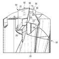
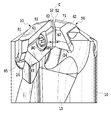
工具本体10は、図12~図16に示すように、その先端部の、回転軸線Cに関して180度回転対称な位置に、2つの突出部11を有する。この突出部11は、工具本体10の先端部が切削インサート50の形状に沿って切り欠かれることにより形成されている。
この2つの突出部11には、それぞれの切削インサート50の第1の当接面81が当接する第1の座面21が形成されているとともに、この第1の座面21を貫通するねじ穴40がそれぞれ形成されている。第1の座面21どうしは、回転軸線Cを挟んで互いに対向し、回転軸線Cに対して平行である。2つの突出部11の間で延在する面は、回転軸線Cに関して180度回転対称な傾斜面(平面)からなる第2の座面23となっている。第2の座面23は、回転軸線C側から半径方向外側にいくにしたがって、工具本体10の後端側に向けて傾斜している。したがって、第1の座面21を含む平面とこれに対応する第2の座面23を含む平面とがなす角度は、鋭角となっている。この構成により、切削インサート50を締め付けネジSCで締結した際に、切削インサート50は確実にクランプされる。また、第1の座面21と、第2の座面23とがなす角度が鋭角となることで、切削インサート50に主分力が加わったときに、切削インサート50の工具本体10の後方側に位置する端部が浮き上ることが抑制される。第3の座面25は、第2の座面23の近傍に形成され、第2の座面23側を向くように傾斜した平面からなる。この第3の座面25を構成し工具本体10の外周方向を向く壁部分26は、外刃51を保護する機能を果たす。
第1の座面21を含む平面とこれに対応する第2の座面23との間には、第1の座面21に沿って延びる凹状の湾曲面をもつ凹部30が形成される。この凹部30は、切削インサート50の2つの切れ刃のうち、切削に使用しない方の切れ刃をカバーして保護するためのものである。この凹部30で少なくとも外刃51を覆うことで、切削加工中等に使用していない切れ刃が損傷するのを防ぐことができる。この実施形態では、凹部30は溝形状として形成される。また別の実施形態において、凹部30は切削加工中等に使用していない切れ刃全体を覆うような形状とすることも可能である。
また、工具本体10の外周面には、らせん状の2つの切りくず搬送溝15が長手方向に形成されている。切りくず搬送溝15は、図12に示す、第2の座面23に隣接する凹状の湾曲面24に連なっている。この湾曲面24は、図13に示すように、回転軸線Cと平行な方向において、内刃52の直下に位置している。この湾曲面24により、内刃52で生成された切りくずが、スムーズに切りくず搬送溝15へ誘導される。
2つの切削インサート50の内刃52は先端視したとき、回転軸線Cを挟んで互いに対向して配置され、かつ、両方の内刃52の頂部が回転軸線Cの方を向くように凸状に湾曲している。すなわち、先端視したとき、2つの内刃51は、回転軸線Cに関してほぼ180度回転対称な位置に配置され、内刃51の間の間隔GP1は、回転軸線Cから半径方向に離れるにしたがって徐々に拡大している。2つの切削インサート50の内刃52は、対向しているので、切削加工中にこの2つの内刃52の間に円柱状の非切削加工部分が形成される。
また、図4に示すように、D方向からみると、2つの切削インサートの内刃52をそれぞれ形成する互いに対向する第2のすくい面62の間の間隔GP2は、回転軸線Cと平行な方向において工具本体10の側に向かって徐々に拡大している。すなわち、間隔GP2は工具本体10の先端側(図面上方)から工具本体10の後端側(図面下方)に向かうにしたがい広くなっている。なお、D方向とは、回転軸線Cを、互いに対向する第2のすくい面62の間および互いに対向する内刃52の間を通過する平面に沿った方向である。上記のように定義される「D方向」は唯ひとつには定まらないが、間隔GP2は上記のように定義される全ての方向から見たときに、工具本体10の側に向かって徐々に拡大するように形成されている。
図2に示すように、2つの切削インサート50の内刃52をそれぞれ形成する2つの第2の逃げ面71は、回転切削工具の回転方向後方に向かうに従って工具本体10の後端側に向かって傾斜し、なおかつ、回転軸線C側に近づくに従って工具本体10の後端側に向かって傾斜している。
本実施形態では、2つの内刃52の間には、回転軸線Cを中心として、間隙が形成される。このため、切削加工中には、工具の中心部には、円柱状の非切削部分が形成される。この円柱状の非切削部分は刃先交換式回転工具に押されてワークから除去されると、通常ならば切削インサートどうしの隙間に詰まり易いが、本実施形態においては上記したように、間隔GP1が回転軸線Cから半径方向に離れるにしたがって徐々に拡大しているので、外周側に向かって排出され易くなる。また、第2のすくい面62の間の間隔GP2も工具本体10側に向かって拡大しているので、この方向においても、切りくずが詰まりにくくなる。このように、切削インサートの間に形成される隙間が、同時に2つの方向に向かって拡大する形状をしているので、本実施形態の刃先好感式回転切削工具は従来の刃先交換式回転切削工具よりも、切りくず排出性能が高い。
さらに、図2に示すように、2つの第2の逃げ面71は、回転軸線C側に近づくに従って工具本体10の後端側に向かって傾斜しているので、切れ刃よりも工具本体10の後端側に凹み、穴底と干渉することがない。
図17A,17Bは、第1の実施形態の第1変形例である。図17A,17Bに示す工具は、それぞれ異なる工具本体10A,10Bに共通の切削インサートを取り付けたものである。なお、図17A,17Bにおいて、第1の実施形態と同一構成部分については同一の符号を使用している。図17Bに示す工具本体10Bの工具径は、図17Aに示す工具本体10Aの工具径よりも大きくなっている。すなわち、本実施形態に係る切削インサート50は、2つの内刃52を回転軸線Cを挟んで対向配置させるので、内刃52が回転軸線Cを挟んで互いに対向する範囲内で外刃51の切削可能な最大直径を変更できる。特に、本実施形態では、内刃52を凸状に湾曲させているので、2つの内刃52を回転軸線Cを挟んで対向配置させることができる範囲が、内刃が直線状である場合よりも広い。
図18および図19は、第1の実施形態の第2変形例である。なお、図18および図19において、第1の実施形態と同一構成部分については同一の符号を使用している。
図18および図19に示すように、それぞれの切削インサート50Bの第1の当接面81にチップスプリッタ100が形成されている。チップスプリッタ100は、別名でニックとも呼ばれる。チップスプリッタ100は、第1の当接面81に形成される凹溝で、切削インサート50の厚み方向に延びている。そして、一方のチップスプリッタ100の形成位置と、他方のチップスプリッタ100の形成位置とは対称軸線Jに関して180度回転対称ではない。このような構成を採用することで、図18に示すように2つのチップスプリッタ100の配置を工具本体10の半径方向において異ならせることができるので、工具本体10が一回転するうちに、異なる位置で切りくずを切断でき、切りくずの切断効率が改善する。
第2実施形態
次に、図20~図28を参照して、本発明の第2実施形態に係る刃先交換式回転切削工具および切削インサートについて説明する。なお、図23~図28において、第1の実施形態と同一構成部分については同一の符号を使用している。
次に、図20~図28を参照して、本発明の第2実施形態に係る刃先交換式回転切削工具および切削インサートについて説明する。なお、図23~図28において、第1の実施形態と同一構成部分については同一の符号を使用している。
第2の実施形態と第1の実施形態とが異なる点は、切削インサートの形状である。本実施形態に係る切削インサート50Aの2つの内刃52,52Aは、異なる形状を有し、かつ、上記した対称軸線Jに関して非対称である。
具体的には、本実施形態に係る切削インサート50Aは、上面には第1の実施形態と同じ形状の第2のすくい面62が形成され、下面には第2のすくい面62とは形状が異なる第3のすくい面62Aが形成されている。この第3のすくい面62Aは、第1のすくい面61の接続領域63において接続され、かつ、第1のすくい面61とは異なる向きに傾斜するとともに凹状に湾曲している。第4のすくい面62Bが第3のすくい面62Aに隣接して形成され、これは平坦な面となっている。また、第2のすくい面62と交差する第2の逃げ面71と、第3のすくい面62Aと交差する第2の逃げ面71とは形状が異なる第3の逃げ面71Aとが側面に形成されている。そして、第2のすくい面62と第2の逃げ面71との交差部に、第1の実施形態の内刃と同じ形状の第1の内刃52が形成され、第3のすくい面62Aと第3の逃げ面71Aとの交差部および第4のすくい面62Bと第3の逃げ面71Aとの交差部に、第1の内刃52とは異なる形状の第2の内刃52Aが形成されている。
第1の内刃52は、第1の実施形態で説明したように、対称軸線Jの方向から見て、回転軸線Cに向かって凸状に湾曲し、図26に示すように、第2の内刃52Aは、対称軸線Jの方向から見て、凹状に湾曲した部分と直線状の部分とで形成されている。すなわち、第3のすくい面62Aの形状と第4のすくい面62Bの形状とを異ならせることにより、第2の内刃52Aは直線および回転軸線Cに対して凹状に湾曲した曲線で形成される。このとき、第2の内刃52Aから回転軸線Cまでの最短距離は、第1の内刃51から回転軸線Cまでの距離よりも長い。つまり、第2の内刃52Aは、半径方向にオフセットしており、第1の内刃52よりも半径方向外側に配置されている。
第1の内刃51および第2の内刃52Aを非対称で、かつ、半径方向にオフセットさせると、工具の中心部で形成される円柱状の切りくずの直径は、第1の内刃51と回転軸線Cとの距離によって規定される。このため、オフセットされた第2の内刃52Aと円柱状の切りくずとの間には、隙間が形成される。この結果、第1の内刃51および第2の内刃52Aとの間に切りくずが詰まりにくくなる。
また、本実施形態の刃先交換式回転切削工具の中心部に形成される円柱状の切りくずは、第1の内刃51だけから力を受けるため、円柱状の切りくず、特に円柱状の非切削部分に、折ろうとする曲げの力を、常に加えることができる。これにより、円柱状の切りくずが工具本体10の外周方向に排出されやすくなる。
上記実施形態では、本発明をドリルに適用した場合について説明したが、これに限定されるわけではなく、例えば、プランジング加工用の工具や底刃つきのエンドミルなどの、回転軸線方向に送りを与えながら切削する工具であれば適用可能である。
また、上記第1の実施形態では、両方の内刃を同じ形状としたが、両方の内刃が凸曲線で、なおかつ一方の内刃と他方の内刃とを比べたとき、一方の内刃から回転軸までの最短距離の方が、他方側の最短距離よりも長くなるような形状を採用することも可能である。
また、上記の実施形態ではいずれも2枚刃であったが、本発明の刃先交換式回転切削工具は3つ以上の切削インサートを備える構造にすることも可能である。
外刃に関しても、上記の実施形態では直線であったが、切削インサートの厚みが減じる方向に向かって湾曲する凹曲線状に形成されても良い。外刃がこのような形状になると、生成された切りくずに対してそれを横から曲げようとする力を発生させることができるので、切りくずが細分化され易くなる。
本明細書で用いられている用語に関する定義についても説明する。本発明において「内刃と内刃とが回転軸線を挟んで対向する」とは、刃先交換式回転切削工具として機能する程度に内刃どうしが近接し、かつ、2つの内刃が形成する隙間の開口部の少なくとも一方が中心から外周に向けて末広がりに形成されることをいう。
本発明において「回転軸線Cの近傍」とは、内刃が穴あけ加工ができる刃先交換式回転切削工具の切れ刃として機能する程度に回転軸線Cに近接していることである。
10…工具本体
15…切りくず搬送溝
50…切削インサート
51…外刃
52…内刃
71…第2の逃げ面
61…第1のすくい面
62…第2のすくい面
62A…第3のすくい面
62B…第4のすくい面
63…すくい面の接続領域
81…第1の当接面(第1の逃げ面)
82…接続面
83…第2の当接面
85…第3の当接面
21…第1の座面
23…第2の座面
25…第3の座面
SC…締め付けネジ
C…回転軸線
AX…中心軸線
15…切りくず搬送溝
50…切削インサート
51…外刃
52…内刃
71…第2の逃げ面
61…第1のすくい面
62…第2のすくい面
62A…第3のすくい面
62B…第4のすくい面
63…すくい面の接続領域
81…第1の当接面(第1の逃げ面)
82…接続面
83…第2の当接面
85…第3の当接面
21…第1の座面
23…第2の座面
25…第3の座面
SC…締め付けネジ
C…回転軸線
AX…中心軸線
Claims (15)
- 回転軸線(C)のまわりに回転可能な工具本体(10)と、該工具本体(10)の先端領域に着脱可能に装着される切削インサート(50)とを有する刃先交換式回転切削工具であって、
複数の前記切削インサート(50)が、前記回転軸線(C)に関して回転対称な位置に配置され、該複数の切削インサート(50)の各々は、前記回転軸線側から外周側へ延びる外刃(51)と、前記外刃(51)と接続され、かつ、前記回転軸線(C)側に配置される内刃(52)と、を有し、
当該工具本体(10)の先端側からみて、当該複数の切削インサート(50)の少なくとも1つの前記内刃(52)が前記回転軸線(C)に対して凸状に湾曲している、ことを特徴とする刃先交換式回転切削工具。 - 前記切削インサート(50)が2つ装着され、該2つの切削インサート(50)の内刃(52)の互いに対向するすくい面(62)の間隔(GP2)は、前記回転軸線(C)に直交し、かつ両方のすくい面(62)が見える方向から見たときに、前記工具本体(10)の後端側に向かって拡大している、ことを特徴とする請求項1に記載の刃先交換式回転切削工具。
- 前記内刃(52)の長さは該切削インサート(50)の切れ刃の長さの10%以上、かつ40%以下とされ、前記内刃(52)の逃げ面(71)は、該回転切削工具の回転方向後方に向かうに従って前記工具本体(10)の後端側に向かって傾斜し、かつ、前記回転軸線(C)側に近づくに従って前記工具本体(10)の後端側に向かって傾斜している、ことを特徴とする請求項1又は2に記載の刃先交換式回転切削工具。
- 前記回転軸線(C)方向から見たとき、前記2つの切削インサート(50)の内刃(52)は、いずれも前記回転軸線(C)に対して凸状に湾曲し、前記回転軸線(C)に関して回転対称な位置に配置され、前記2つの切削インサート(50)の内刃(52)の間隔(GP2)が、前記回転軸線(C)から半径方向に離れるにしたがって徐々に拡大している、ことを特徴とする請求項2に記載の刃先交換式回転切削工具。
- 前記複数の切削インサート(50)の各々は、板状に形成され、
外周側面に形成された、互いに平行でかつ、前記工具本体(10)の第1の座面(21)に当接する2つの第1の当接面(81)と、
前記2つの第1の当接面(81)の間に形成され、かつ、前記第1の当接面(81)に平行な中心軸線(AX)を有する切削インサート取り付け用の貫通穴(90)と、
上面および下面にそれぞれ形成され、互いに平行で、かつ、前記工具本体(10)の第2の座面(23)に当接する第2の当接面(83)と、
前記上面および下面に前記第2の当接面(83)からそれぞれ突出するように形成され、前記第2の当接面(83)に対して傾斜し、かつ、前記外刃(51)に接続する第1のすくい面(61)と、
前記上面および下面にそれぞれ形成され、前記第1のすくい面(61)と接続され、前記第1のすくい面(61)とは異なる向きに傾斜し、かつ、前記内刃(52)に接続する第2のすくい面(62)と、
前記第1の当接面(81)と同一面として形成され、かつ、前記第1のすくい面(61)と交差する第1の逃げ面(81)と、
前記外周側面にそれぞれ形成され、前記第2のすくい面(62)と交差する第2の逃げ面(71)と、を有し、
前記複数の切削インサート(50)の各々は、前記中心軸線(AX)に直交し、かつ、前記第1の当接面(81)に平行な対称軸線(J)に関して180度回転対称である、ことを特徴とする請求項1ないし4のいずれかに記載の刃先交換式回転切削工具。 - 前記第2の逃げ面(71)に対向する方向から見て、前記内刃(52)は、凸状に湾曲している、ことを特徴とする請求項5に記載の刃先交換式回転切削工具。
- 前記切削インサート(50)が2つ装着され、該2つの切削インサート(50)の一方の切削インサート(50)の内刃(52)は、前記回転軸線(C)に対して凸状に湾曲し、他方の切削インサート(50)の内刃(52)は、直線状に形成され又は前記回転軸線(C)に対して凹状に湾曲して形成され、
前記他方の切削インサート(50)の内刃(52)から前記回転軸線(C)までの最短距離は、前記一方の切削インサート(50)の内刃(52)から前記回転軸線(C)までの距離よりも長い、ことを特徴とする請求項1ないし3のいずれかに記載の刃先交換式回転切削工具。 - 前記2つの切削インサート(50)の各々は、板状に形成され、
外周側面に形成された、互いに平行で、かつ、前記工具本体(10)の第1の座面(21)に当接する第1の当接面(81)と、
前記2つの第1の当接面(81)の間に形成され、かつ、前記第1の当接面(81)に平行な中心軸線(AX)を有する切削インサート取り付け用の貫通穴(90)と、
上面および下面にそれぞれ形成され、互いに平行で、かつ、前記工具本体(10)の第2の座面(23)に当接する第2の当接面(83)と、
前記上面および下面に前記第2の当接面(83)からそれぞれ突出するように形成され、前記第2の当接面(83)に対して傾斜し、かつ、前記外刃(51)に接続する第1のすくい面(61)と、
前記切削インサート(50)の上面に形成され、前記第1のすくい面(61)と接続され、前記第1のすくい面(61)とは異なる向きに傾斜する第2のすくい面(62)と、
前記切削インサート(50)の下面に形成され、前記第1のすくい面(61)と接続され、前記第1のすくい面(61)とは異なる向きに傾斜する第3のすくい面(62A)と、
前記第1の当接面(81)と同一面として形成され、かつ、前記第1のすくい面(61)と交差する第1の逃げ面(81)と、
前記外周側面に形成され、前記第2のすくい面(62)と交差する第2の逃げ面(71)と、
前記外周側面に形成され、前記第3のすくい面(62A)と交差する第3の逃げ面(71A)と、を有し、
前記第2のすくい面(62)と前記第2の逃げ面(71)との交差部に、第1の内刃(52)が形成され、
前記第3のすくい面(62A)と前記第3の逃げ面(71A)との交差部に、第2の内刃(52A)が形成され、
前記第1の内刃(52)は、前記第2の逃げ面(71)に対向する方向から見て、凸状に湾曲し、
前記第2の内刃(52A)は、前記第3の逃げ面(71A)に対向する方向から見て、直線状に形成され、又は、凹状に湾曲して形成されている、ことを特徴とする請求項7に記載の刃先交換式回転切削工具。 - 前記工具本体(10)は、前記複数の切削インサート(50)の第1の当接面(81)がそれぞれ当接する第1の座面(21)と、前記切削インサート(50)の第2の当接面(83)がそれぞれ当接する第2の座面(23)とを有し、
前記第1の座面(21)と対応する第2の座面(23)との間に、切削に使用されない側の少なくとも外刃(51)をカバーして保護するための凹部(30)が形成されている、ことを特徴とする請求項1ないし3のいずれかに記載の刃先交換式回転切削工具。 - 前記第1の座面(21)と対応する第2の座面(23)とがなす角度が鋭角となっている、ことを特徴とする請求項1ないし3のいずれかに記載の刃先交換式回転切削工具。
- 前記第1の逃げ面(81)のそれぞれに、上下の前記外刃(51)まで延びるチップスプリッタ(100)が形成され、
一方の前記第1の逃げ面(81)への前記チップスプリッタ(100)の形成位置と、他方の前記第1の逃げ面(81)への前記チップスプリッタ(100)の形成位置とが互いに異なる、ことを特徴とする請求項1ないし3のいずれかに記載の刃先交換式回転切削工具。 - 回転軸線(C)のまわりに回転可能な工具本体(10)の先端領域の前記回転軸線(C)の周りの複数個所に着脱可能に配置される切削インサート(50)であって、
前記切削インサート(50)は、板状に形成され、上面または下面の少なくとも一方と外周側面との交差稜線に切れ刃が形成され、該切れ刃は外刃(51)と、外刃(51)に対して傾斜する内刃(52)とを有し、
前記外周側面に形成された、互いに平行な第1の当接面(81)と、
前記2つの第1の当接面(81)の間に形成され、かつ、前記第1の当接面(81)に平行な中心軸線(AX)を有する貫通穴(90)と、
上面および下面にそれぞれ形成され、互いに平行な第2の当接面(83)と、
前記上面または下面の少なくとも1方に前記第2の当接面(83)から突出するように形成され、前記第2の当接面(83)に対して傾斜し、かつ、前記外刃(51)と接続する第1のすくい面(61)と、
該第1のすくい面(61)と接続され、前記第1のすくい面(61)とは異なる向きに傾斜し、かつ、前記内刃(52)と接続する第2のすくい面(62)と、
前記第1の当接面(81)と同一面として形成され、かつ、前記第1のすくい面(61)と交差する第1の逃げ面(81)と、
前記外周側面に形成され、前記第2のすくい面(62)と交差する第2の逃げ面(71)と、を有し、
前記第2の逃げ面(71)に対向する方向から見て、少なくとも1つの前記内刃(52)は凸状に湾曲している、ことを特徴とする切削インサート。 - 前記中心軸線(C)に直交し、かつ、前記第1の当接面(81)に平行な対称軸線に関して180度回転対称であることを特徴とする請求項12に記載の切削インサート。
- 前記第2のすくい面(62)は、前記切削インサート(50)の上面に形成され、
前記切削インサート(50)の下面に形成され、前記第1のすくい面(61)と接続され、前記第1のすくい面(61)とは異なる向きに傾斜する第3のすくい面(62A)と、
前記外周側面に形成され、該第3のすくい面(62A)と交差する第3の逃げ面(71A)と、を有し、
前記第2のすくい面(62)と前記第2の逃げ面(71)との交差部に、第1の内刃(52)が形成され、
前記第3のすくい面(62A)と前記第3の逃げ面(71A)との交差部に、第2の内刃(52A)が形成され、
前記第1の内刃(52)は、前記第2の逃げ面(71)に対向する方向から見て、凸状に湾曲し、
前記第2の内刃(52A)は、前記第3の逃げ面(71A)に対向する方向から見て、直線状に形成され、又は、凹状に湾曲して形成されている、ことを特徴とする請求項12に記載の切削インサート。 - 前記第1の逃げ面(81)のそれぞれに、上下の前記外刃(51)まで延びるチップスプリッタ(100)が形成され、
一方の前記第1の逃げ面(81)への前記チップスプリッタ(100)の形成位置と、他方の前記第1の逃げ面(81)への前記チップスプリッタ(100)の形成位置とが、前記対称軸線(J)に関して180度回転対称ではない、ことを特徴とする請求項12に記載の切削インサート。
Applications Claiming Priority (2)
| Application Number | Priority Date | Filing Date | Title |
|---|---|---|---|
| JP2011164417A JP2014193491A (ja) | 2011-07-27 | 2011-07-27 | 刃先交換式回転切削工具およびこれに用いる切削インサート |
| JP2011-164417 | 2011-07-27 |
Publications (1)
| Publication Number | Publication Date |
|---|---|
| WO2013015404A1 true WO2013015404A1 (ja) | 2013-01-31 |
Family
ID=47601235
Family Applications (1)
| Application Number | Title | Priority Date | Filing Date |
|---|---|---|---|
| PCT/JP2012/069107 WO2013015404A1 (ja) | 2011-07-27 | 2012-07-27 | 刃先交換式回転切削工具およびこれに用いる切削インサート |
Country Status (2)
| Country | Link |
|---|---|
| JP (1) | JP2014193491A (ja) |
| WO (1) | WO2013015404A1 (ja) |
Cited By (2)
| Publication number | Priority date | Publication date | Assignee | Title |
|---|---|---|---|---|
| WO2016084898A1 (ja) * | 2014-11-27 | 2016-06-02 | 株式会社タンガロイ | 切削インサート、工具ボデーおよび切削工具 |
| CN109158665A (zh) * | 2018-08-14 | 2019-01-08 | 株洲钻石切削刀具股份有限公司 | 可转位钻孔刀具 |
Citations (4)
| Publication number | Priority date | Publication date | Assignee | Title |
|---|---|---|---|---|
| JPH11291102A (ja) * | 1998-04-08 | 1999-10-26 | Mitsubishi Materials Corp | スローアウェイチップおよび該スローアウェイチップを装着したスローアウェイ式ドリル |
| JP2000094210A (ja) * | 1998-09-28 | 2000-04-04 | Mitsubishi Materials Corp | スローアウェイ式穴明け工具 |
| JP2000158220A (ja) * | 1998-11-30 | 2000-06-13 | Ngk Spark Plug Co Ltd | スローアウェイドリル及びそのシャンク |
| JP2010523353A (ja) * | 2007-04-01 | 2010-07-15 | イスカーリミテッド | 切削インサート |
-
2011
- 2011-07-27 JP JP2011164417A patent/JP2014193491A/ja not_active Withdrawn
-
2012
- 2012-07-27 WO PCT/JP2012/069107 patent/WO2013015404A1/ja active Application Filing
Patent Citations (4)
| Publication number | Priority date | Publication date | Assignee | Title |
|---|---|---|---|---|
| JPH11291102A (ja) * | 1998-04-08 | 1999-10-26 | Mitsubishi Materials Corp | スローアウェイチップおよび該スローアウェイチップを装着したスローアウェイ式ドリル |
| JP2000094210A (ja) * | 1998-09-28 | 2000-04-04 | Mitsubishi Materials Corp | スローアウェイ式穴明け工具 |
| JP2000158220A (ja) * | 1998-11-30 | 2000-06-13 | Ngk Spark Plug Co Ltd | スローアウェイドリル及びそのシャンク |
| JP2010523353A (ja) * | 2007-04-01 | 2010-07-15 | イスカーリミテッド | 切削インサート |
Cited By (5)
| Publication number | Priority date | Publication date | Assignee | Title |
|---|---|---|---|---|
| WO2016084898A1 (ja) * | 2014-11-27 | 2016-06-02 | 株式会社タンガロイ | 切削インサート、工具ボデーおよび切削工具 |
| JP5991565B1 (ja) * | 2014-11-27 | 2016-09-14 | 株式会社タンガロイ | 切削インサート、工具ボデーおよび切削工具 |
| CN107000081A (zh) * | 2014-11-27 | 2017-08-01 | 株式会社泰珂洛 | 切削刀片、工具体及切削工具 |
| CN109158665A (zh) * | 2018-08-14 | 2019-01-08 | 株洲钻石切削刀具股份有限公司 | 可转位钻孔刀具 |
| CN109158665B (zh) * | 2018-08-14 | 2020-02-04 | 株洲钻石切削刀具股份有限公司 | 可转位钻孔刀具 |
Also Published As
| Publication number | Publication date |
|---|---|
| JP2014193491A (ja) | 2014-10-09 |
Similar Documents
| Publication | Publication Date | Title |
|---|---|---|
| JP5070225B2 (ja) | 切削インサート、特にドリル用スローアウェイチップ | |
| JP6580572B2 (ja) | 割出し可能な両面切削インサートおよびそれ用の切削工具 | |
| JP6532940B2 (ja) | 両面型切削インサートおよびフライス工具 | |
| JP5491505B2 (ja) | フライスおよびそのための切削チップ | |
| JP5679042B2 (ja) | ガイドパッド、切削工具本体および切削工具 | |
| JP5939355B2 (ja) | 切削インサート及び刃先交換式切削工具 | |
| JP6330913B2 (ja) | 切削インサート及び刃先交換式回転切削工具 | |
| WO2011046121A1 (ja) | 切削インサート及び刃先交換式回転工具 | |
| JP6436093B2 (ja) | 切削インサート及び刃先交換式切削工具 | |
| JP6361948B2 (ja) | 切削インサートおよび切削工具 | |
| JP2018534159A (ja) | 旋削インサートおよび方法 | |
| JPWO2016017780A1 (ja) | 切削インサートおよび刃先交換式切削工具 | |
| JP6011831B2 (ja) | 刃先交換式回転切削工具 | |
| JP5196077B2 (ja) | 切削用インサートおよび刃先交換式転削工具 | |
| JP4125909B2 (ja) | スクエアエンドミル | |
| WO2015137508A1 (ja) | 切削インサート、工具ボデーおよび切削工具 | |
| WO2013015404A1 (ja) | 刃先交換式回転切削工具およびこれに用いる切削インサート | |
| JP2015196203A (ja) | 刃先交換式メタルソー | |
| JP6292425B2 (ja) | 刃先交換式回転切削工具 | |
| JP2022122825A (ja) | 切削インサートおよびこれを備えた切削工具 | |
| JP2008018491A (ja) | サイドカッタ | |
| JP7242997B2 (ja) | 刃先交換式エンドミルのエンドミル本体 | |
| JPH0433565B2 (ja) | ||
| JP4961841B2 (ja) | 中ぐり工具 | |
| JP2007283467A (ja) | 切削インサート及び切削工具 |
Legal Events
| Date | Code | Title | Description |
|---|---|---|---|
| 121 | Ep: the epo has been informed by wipo that ep was designated in this application |
Ref document number: 12817592 Country of ref document: EP Kind code of ref document: A1 |
|
| NENP | Non-entry into the national phase |
Ref country code: DE |
|
| 122 | Ep: pct application non-entry in european phase |
Ref document number: 12817592 Country of ref document: EP Kind code of ref document: A1 |
|
| NENP | Non-entry into the national phase |
Ref country code: JP |