WO2014125929A1 - バルブ制御装置及びバルブ制御方法 - Google Patents
バルブ制御装置及びバルブ制御方法 Download PDFInfo
- Publication number
- WO2014125929A1 WO2014125929A1 PCT/JP2014/052079 JP2014052079W WO2014125929A1 WO 2014125929 A1 WO2014125929 A1 WO 2014125929A1 JP 2014052079 W JP2014052079 W JP 2014052079W WO 2014125929 A1 WO2014125929 A1 WO 2014125929A1
- Authority
- WO
- WIPO (PCT)
- Prior art keywords
- valve
- operation amount
- correction
- control deviation
- state
- Prior art date
Links
Images


Classifications
-
- G—PHYSICS
- G05—CONTROLLING; REGULATING
- G05D—SYSTEMS FOR CONTROLLING OR REGULATING NON-ELECTRIC VARIABLES
- G05D7/00—Control of flow
- G05D7/06—Control of flow characterised by the use of electric means
- G05D7/0617—Control of flow characterised by the use of electric means specially adapted for fluid materials
- G05D7/0629—Control of flow characterised by the use of electric means specially adapted for fluid materials characterised by the type of regulator means
- G05D7/0635—Control of flow characterised by the use of electric means specially adapted for fluid materials characterised by the type of regulator means by action on throttling means
-
- F—MECHANICAL ENGINEERING; LIGHTING; HEATING; WEAPONS; BLASTING
- F02—COMBUSTION ENGINES; HOT-GAS OR COMBUSTION-PRODUCT ENGINE PLANTS
- F02D—CONTROLLING COMBUSTION ENGINES
- F02D41/00—Electrical control of supply of combustible mixture or its constituents
- F02D41/02—Circuit arrangements for generating control signals
- F02D41/14—Introducing closed-loop corrections
- F02D41/1401—Introducing closed-loop corrections characterised by the control or regulation method
-
- G—PHYSICS
- G05—CONTROLLING; REGULATING
- G05B—CONTROL OR REGULATING SYSTEMS IN GENERAL; FUNCTIONAL ELEMENTS OF SUCH SYSTEMS; MONITORING OR TESTING ARRANGEMENTS FOR SUCH SYSTEMS OR ELEMENTS
- G05B15/00—Systems controlled by a computer
- G05B15/02—Systems controlled by a computer electric
-
- F—MECHANICAL ENGINEERING; LIGHTING; HEATING; WEAPONS; BLASTING
- F01—MACHINES OR ENGINES IN GENERAL; ENGINE PLANTS IN GENERAL; STEAM ENGINES
- F01P—COOLING OF MACHINES OR ENGINES IN GENERAL; COOLING OF INTERNAL-COMBUSTION ENGINES
- F01P7/00—Controlling of coolant flow
- F01P7/14—Controlling of coolant flow the coolant being liquid
- F01P2007/146—Controlling of coolant flow the coolant being liquid using valves
-
- F—MECHANICAL ENGINEERING; LIGHTING; HEATING; WEAPONS; BLASTING
- F02—COMBUSTION ENGINES; HOT-GAS OR COMBUSTION-PRODUCT ENGINE PLANTS
- F02D—CONTROLLING COMBUSTION ENGINES
- F02D41/00—Electrical control of supply of combustible mixture or its constituents
- F02D41/02—Circuit arrangements for generating control signals
- F02D41/14—Introducing closed-loop corrections
- F02D41/1401—Introducing closed-loop corrections characterised by the control or regulation method
- F02D2041/1409—Introducing closed-loop corrections characterised by the control or regulation method using at least a proportional, integral or derivative controller
Definitions
- the present invention relates to a valve control device and a valve control method for controlling an electronic control valve.
- valves to be controlled by this technology include engine throttle valves and cooling water valves.
- PID Proportional Integral Derivative
- Examples of valves to be controlled by this technology include engine throttle valves and cooling water valves.
- a throttle valve control there is a problem that the actual measurement value of the controlled object does not reach the required target value due to the occurrence of hysteresis caused by the frictional resistance between the parts of the control mechanism.
- a valve control device that enables quick and accurate control from the target value to the required target value (see, for example, Patent Document 1).
- the elapsed time from the energization of the actuator calculated by the controller to the change in water temperature is calculated, the water temperature after the elapsed time is predicted, and the predicted water temperature is calculated.
- Patent Document 2 there is known a technique that realizes high followability of the cooling water temperature by controlling the actuator in advance (see, for example, Patent Document 2).
- the above-described throttle valve adjusts the amount of air sucked into the engine, whereas the cooling water valve adjusts the flow rate of cooling water that cools the engine.
- the settling performance to the target opening degree is deteriorated, that is, the controllability of the flow rate adjustment of the cooling water is deteriorated.
- a factor different from the throttle valve is, for example, that the friction becomes unstable due to a stick-slip phenomenon occurring between the cooling water valve and the seal member.
- Such a problem is not limited to the cooling water valve, and is a problem that can occur in general control of a valve that adjusts the flow rate of fluid.
- the present invention has been made to solve the above-described problems, and in the control of a valve that adjusts the flow rate of a fluid, a valve control device and a valve control that can improve the stability of the valve to a target opening degree. It aims to provide a method.
- one aspect of the present invention is an operation of the drive device at a predetermined sampling cycle based on a control deviation between a target value of the valve opening and an actual measured value of the valve opening.
- An operation amount calculation unit that calculates an amount, a state determination unit that determines whether the valve is in a steady state or a transient state, and when the state determination unit determines that the valve is in a steady state,
- a first correction unit that outputs a predetermined first correction value corresponding to the sign of the control deviation and corrects the operation amount calculated by the operation amount calculation unit with the first correction value;
- the stability of the valve to the target opening can be improved in the control of the valve for adjusting the flow rate of the fluid.
- FIG. 1 is a schematic diagram showing an engine cooling system according to the present embodiment.
- the engine cooling system 1 includes an engine 11, a water jacket 12, a water pump 13, a cooling water valve 21, a motor 22, a position sensor 23, a water temperature sensor 24, an ECU (Engine Control). Unit) 31, a radiator 41, a heater 42, a throttle 43, a main flow path pipe 91, a sub flow path pipe 92, and a bypass flow path pipe 93.
- the engine cooling system 1 circulates cooling water through the main flow path pipe 91, the sub flow path pipe 92, or the bypass flow path pipe 93, and controls the temperature of the engine 11 by the water jacket 12.
- the engine 11 is an internal combustion engine of a vehicle such as an automobile.
- the water jacket 12 is provided in the vicinity of the engine 11 and cools the engine 11 with cooling water therein.
- the main flow path pipe 91 allows cooling water to flow into the radiator 41.
- the sub passage pipe 92 allows cooling water to flow into the heater 42 and the throttle 43.
- the bypass flow path pipe 93 allows the cooling water flowing out from the water jacket 12 to flow into the water pump 13.
- the cooling water that has flowed into the radiator 41, the heater 42, and the throttle 43 flows into the water pump 13.
- the water pump 13 allows cooling water to flow into the water jacket 12.
- the radiator 41 cools the cooling water.
- the heater 42 warms the passenger compartment.
- the throttle 43 controls the amount of exhaled air flowing into the engine 11.
- the cooling water valve 21 is a rotary type valve, and an opening is provided in a part of the outer peripheral surface, and the cooling water flows into the main passage pipe 91 and the sub passage pipe 92 depending on the opening degree.
- the motor 22 is a DC motor as an actuator that drives the cooling water valve 21.
- the position sensor 23 detects the opening degree of the cooling water valve 21 relative to the main flow path pipe 91 and the sub flow path pipe 92 by detecting the circumferential position of the cooling water valve 21.
- the water temperature sensor 24 detects the temperature of the cooling water.
- the ECU 31 includes a processor and a memory, and is a microcontroller that controls various operations related to the engine 11. In this embodiment, the ECU 31 detects the position of the cooling water valve 21 and the cooling water detected by the water temperature sensor 24 and the position sensor 23. It is assumed that the operation of the motor 22 is operated based on the temperature.
- the cooling water is cooled by the radiator 41 by being circulated through the main flow path pipe 91, and is circulated without being cooled when it is routed through the bypass flow path pipe 93. Further, the engine cooling system 1 controls the temperature of the engine 11 by switching the cooling water circulation path according to the opening degree of the cooling water valve 21 and controlling the amount of cooling water flowing into the main passage pipe 91. .
- FIG. 2 is a schematic view showing a cooling water valve and a seal member.
- seal members 91 a and 92 a are provided in the vicinity of the cooling water inlets of the main passage pipe 91 and the sub passage pipe 92 so as to cover the outer peripheries thereof.
- the cooling water valve 21 changes the position of the opening with respect to the main flow path pipe 91 and the sub flow path pipe 92 by rotating in the circumferential direction about the rotation shaft 21a.
- the amount of cooling water flowing into the main flow path pipe 91 and the sub flow path pipe 92 is adjusted by the position of the opening. In such a configuration, hysteresis friction, stick slip, and the like occur between the cooling water valve 21 and the seal members 91a and 92b.
- the area where the coolant valve 21 and the seal members 91a and 92b are in contact with each other varies depending on the position of the opening, and the friction coefficient also varies accordingly.
- FIG. 3 is a block diagram illustrating a hardware configuration of the ECU.
- the ECU 31 includes a CPU (Central Processing Unit) 311, a memory 312, and an input / output interface 313.
- the CPU 311 and the memory 312 cooperate to perform processing related to the control of the cooling water valve 21.
- the input / output interface 313 is an interface related to the input / output of the CPU 311, and the CPU 311 acquires the detection results by the position sensor 23 and the water temperature sensor 24 through the input / output interface 313, and the motor through the input / output interface 313.
- a signal corresponding to the operation amount 22 is output to the drive circuit 25.
- the drive circuit 25 is a PWM circuit that controls the motor 22 by PWM (Pulse Width Modulation), and drives the motor 22 by changing the duty ratio of the pulse width according to the magnitude of the input signal.
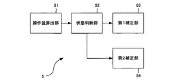
- FIG. 4 is a functional block diagram showing a functional configuration of the valve control device.
- the control target is limited to the opening degree of the water cooling valve 21.
- the valve control device 5 includes an operation amount calculation unit 51, a state determination unit 52, a first correction unit 53, and a second correction unit 54 as functions. Note that these functions are realized by the cooperation of the CPU 311 and the memory 312 described above.
- the operation amount calculation unit 51 applies the target water jacket 12 for setting the engine 11 to the target temperature based on the target temperature that is the target temperature of the engine 11 and the temperature of the cooling water detected by the water temperature sensor 24.
- a target flow rate that is the flow rate of the cooling water is calculated, and a target opening value (target value) that is the target opening degree of the cooling water valve 21 is calculated based on the target flow rate.
- the operation amount calculation unit 51 calculates the operation amount for the motor 22 by PID control based on the calculated target value and the actual opening (current value) of the cooling water valve 21 detected by the position sensor 23 as feedback. To do.
- the movable range of the cooling water valve 21 is 190 °, and the resolution for driving the motor 22 is 240. Therefore, in the present embodiment, the opening degree of the cooling water valve 21 is controlled in units of 0.344 degrees. In addition, when the operation amount is increased in the positive direction, the cooling water valve 21 is controlled in the opening direction. In addition, the cooling water valve 21 is controlled at a predetermined sampling period.
- the state determination unit 52 performs determination processing for determining whether the cooling water valve 21 is in a steady state or a transient state. This determination process will be described later.
- the first correction unit 53 performs a steady state correction process, which will be described later, when the state determination unit 52 determines that the steady state is set.
- the second correction processing unit 54 performs a transient state correction process described later when the state determination unit 53 determines that the state is a transient state.
- a hysteresis correction value is calculated by the steady state correction process and the transient state correction process, and this hysteresis correction value is integrated and added to the operation amount calculated by the operation amount calculation unit 51.
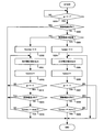
- FIG. 5 is a flowchart showing the operation of the determination process.
- the state determination unit 52 determines whether or not the control deviation is 0 (S101).
- the control deviation indicates a control deviation based on the target value of the coolant valve 21 and the current value.
- the state determination unit 52 determines whether or not the target value calculated by the operation amount calculation unit 51 has been changed (S102).
- the state determination unit 52 substitutes 0 indicating the transient state for the variable gc indicating whether the water cooling valve 21 is in the steady state or the transient state ( S103), it is determined again whether or not the control deviation is 0 (S101).
- the state determination unit 52 determines whether or not the sign of the control deviation is inverted (S104).
- the determination unit 52 determines whether or not the sign of the control deviation at the present time is inverted by comparing with the control deviation of the previous sample.
- the state determination unit 52 determines whether or not the absolute value of the control deviation is 3LSB or less (S105).
- the state determination unit 52 substitutes 1 indicating the steady state for the variable gc (S106), and again determines whether the control deviation is 0 or not. Is determined (S101).
- the state determination unit 52 substitutes 0 indicating the transient state for the variable gc (S103), and again whether the control deviation is 0 or not. Is determined (S101).
- step S104 If the sign of the deviation is not inverted in the determination in step S104 (S104, NO), the state determination unit 52 substitutes 0 indicating the transient state for the variable gc (S103), and again performs control. It is determined whether or not the deviation is 0 (S101).
- step S101 the state determination unit 52 substitutes 1 indicating a steady state for the variable gc (S106), and the control deviation is again present. It is determined whether it is 0 (S101).
- the state determination unit 52 has a case where the control deviation is 0, a case where the sign of the control deviation is inverted in a state where the target value is not changed, and an absolute value of the control deviation is equal to or less than a predetermined value. In addition, it is determined that the cooling water valve 21 is in a steady state. In the above-described processing, the state determination unit 52 waits for the next sample after being assigned to the variable gc.
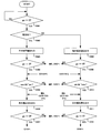
- FIG. 6 is a flowchart showing the operation of the steady state correction process.
- the first correction unit 53 determines whether or not the variable gc is 1 (S201).
- the first correction unit 53 determines whether or not the control deviation is 0 (S202).
- the first correction unit 53 determines whether or not the control deviation is a positive value (S203).
- the first correction unit 53 When the control deviation is a positive value (S203, YES), the first correction unit 53 initializes the counter variable hyspcc by substituting 0 (S204), and outputs a predetermined positive correction value as a hysteresis correction value ( In S205, the variable hyspcc is incremented (S206), the next sample is waited, and it is determined whether or not the variable gc is 1 (S207).
- the first correction unit 53 determines whether or not the control deviation is 0 (S208).
- step S208, NO the first correction unit 53 determines whether or not the variable hyspcc is greater than or equal to maxc which is a variable indicating a predetermined threshold (S209).
- the first correction unit 53 ends the steady state correction process.
- the first correction unit 53 again outputs a predetermined positive correction value as a hysteresis correction value (S205).
- step S208 If the control deviation is 0 in the determination in step S208 (S208, YES), the first correction unit 53 ends the steady state correction process.
- step S207 If the variable gc is not 1 in the determination in step S207 (S207, NO), the first correction unit 53 ends the steady state correction process.
- the first correction unit 53 initializes the variable hyssmc by substituting 0 (S210), and sets a predetermined negative correction value.
- a hysteresis correction value is output (S211), the variable hysmc is incremented (S212), the next sample is waited, and it is determined whether the variable gc is 1 (S213).
- the first correction unit 53 determines whether or not the control deviation is 0 (S214).
- step S214 the first correction unit 53 determines whether or not the variable hyssmc is greater than or equal to the variable maxc (S215).
- the first correction unit 53 ends the steady state correction process.
- the first correction unit 53 outputs a predetermined negative correction value as a hysteresis correction value (S211).
- step S214 If the control deviation is 0 in the determination in step S214 (S214, YES), the first correction unit 53 ends the steady state correction process.
- step S213 If the variable gc is not 1 in the determination in step S213 (S213, NO), the first correction unit 53 ends the steady state correction process.
- step S201 if the variable gc is not 1 (S201, NO), the first correction unit 53 waits for the next sample, and determines again whether the variable gc is 1 ( S201).
- the first correction unit 53 when there is a control deviation in the steady state, the first correction unit 53 outputs a predetermined hysteresis correction value according to the sign. In addition, the first correction unit 53 continues to output the predetermined hysteresis correction value unless the control deviation becomes zero and the number of times of output of the hysteresis correction value reaches the predetermined threshold. That is, the first correction unit 53 outputs the hysteresis correction value in a plurality of times. With such an operation, the controllability of the cooling water valve 21 in a steady state can be improved.
- 7 and 8 are flowcharts showing the operation of the transient state correction process.
- the second correction unit 54 determines whether or not the variable gc is 0 (S301).
- the second correction unit 54 determines whether or not the operation direction of the cooling water valve 21 is the open direction (S302).
- the second correction unit 54 When the operation direction of the coolant valve 21 is the open direction (S302, YES), the second correction unit 54 outputs a predetermined positive correction value as a hysteresis correction value (S303), and waits for the next sample. Then, it is determined whether or not the variable gc is 0 (S304).
- the second correction unit 54 determines whether the variable mns is 1 and the variable pls is 0 (S305).
- variable mns is set to 1 when the operation amount of the current sample has decreased with respect to the operation amount of the previous sample and the operation amount of the previous sample has not decreased with respect to the operation amount of the previous sample, otherwise In this case, it becomes 0.
- variable pls is 1 when the operation amount of the current sample has increased with respect to the operation amount of the previous sample, and the operation amount of the previous sample has not increased with respect to the operation amount of the previous sample, Otherwise it is 0.
- the second correction unit 54 When the variable mns is 1 and the variable pls is 0 (S305, YES), the second correction unit 54 outputs a predetermined negative correction value as a hysteresis correction value (S306), and waits for the next sample. It is determined whether or not the variable gc is 0 (S307).
- step S302 If it is determined in step S302 that the operation direction of the cooling water valve 21 is the closing direction (S302, NO), the second correction unit 54 outputs a predetermined negative correction value as a hysteresis correction value (S308), The next sample is waited, and it is determined whether or not the variable gc is 0 (S309).
- the second correction unit 54 determines whether the variable pls is 1 and the variable mns is 0 (S310).
- the second correction unit 54 When the variable pls is 1 and the variable mns is 0 (S310, YES), the second correction unit 54 outputs a predetermined positive correction value as a hysteresis correction value (S311), and waits for the next sample. It is determined whether or not the variable gc is 0 (S312).
- the second correction unit 54 determines whether the variable mns is 1 and the variable pls is 0 (S305).
- the second correction unit 54 ends the transient state correction process as shown in FIG.
- step S307 when the variable gc is 0 (S307, YES), the second correction unit 54 determines whether the variable pls is 1 and the variable mns is 0 (S310).
- the second correction unit 54 performs the transient state correction process. Exit.
- step S305 when the variable mns is 1 and the variable pls is not 0 (S305, NO), and in the determination in step S310, the variable pls is 1 and the variable mns is not 0 (S310, NO).
- the second correction unit 54 performs a process of step S ⁇ b> 313 described later.
- step S301 If the variable gc is not 0 in the determination in step S301 (S301, NO), the second correction unit 54 waits for the next sample and determines again whether the variable gc is 0 ( S301).
- the second correction unit 54 outputs a correction value 0 (S313) as shown in FIG. 8, waits for the next sample, and determines whether the variable gc is 0 or not. (S314).
- the second correction unit 54 determines whether or not the variable mns is 1 and the variable pls is 0 (S315).
- the second correction unit 54 When the variable mns is 1 and the variable pls is 0 (S315, YES), the second correction unit 54 outputs a predetermined negative correction value as a hysteresis correction value as shown in FIG. 7 (S306).
- the second correction unit 54 outputs a predetermined positive correction value as a hysteresis correction value as shown in FIG. 7 (S311). .
- step S314 If the variable gc is not 0 in the determination in step S314 (S314, NO), the second correction unit 54 ends the transient state correction process.
- the second correction unit 54 outputs a negative correction value when the operation amount starts to decrease in the transient state, and outputs a positive correction value when the operation amount starts to increase. With such an operation, the controllability of the cooling water valve 21 in a transient state can be improved.
- the hysteresis correction value is output according to the steady state and the transient state, so that the target opening of the cooling water valve 21 is achieved particularly in the steady state.
- the stability to the degree can be improved. This also improves the controllability of the flow rate of the cooling water, and therefore the controllability of the temperature of the engine 11 can also be improved.
- the control target of the valve control device 5 is the cooling water valve 21, but the valve control device 5 is applicable as long as it is a valve that controls the flow rate of fluid.
Landscapes
- Engineering & Computer Science (AREA)
- General Engineering & Computer Science (AREA)
- Physics & Mathematics (AREA)
- General Physics & Mathematics (AREA)
- Automation & Control Theory (AREA)
- Chemical & Material Sciences (AREA)
- Combustion & Propulsion (AREA)
- Mechanical Engineering (AREA)
- Electrical Control Of Air Or Fuel Supplied To Internal-Combustion Engine (AREA)
- Combined Controls Of Internal Combustion Engines (AREA)
- Magnetically Actuated Valves (AREA)
- Electrically Driven Valve-Operating Means (AREA)
Abstract
Description
Claims (8)
- バルブを駆動する駆動装置を制御するバルブ制御装置であって、
前記バルブの開度の目標値と前記バルブの開度の実測値との制御偏差に基づいて、所定のサンプリング周期で前記駆動装置の操作量を算出する操作量算出部と、
前記バルブが定常状態または過渡状態のいずれであるかを判断する状態判断部と、
前記状態判断部により前記バルブが定常状態であると判断された場合、前記制御偏差の符号に応じた所定の第1補正値を出力し、前記操作量算出部で算出された操作量を該第1補正値で補正する第1補正部と、
を備えるバルブ制御装置。 - 前記第1補正部は、前記第1補正値の出力回数が所定の第1閾値より少ない場合、前記第1補正値の出力を前記制御偏差がゼロになるまで継続することを特徴とする、
請求項1に記載のバルブ制御装置。 - 前記状態判断部は、前記目標値が変更されない状態において、前記制御偏差の符号が前回のサンプルにおける制御偏差の符号に対して反転し、且つ前記制御偏差の絶対値が所定の第2閾値以下である場合、前記バルブが定常状態であると判断することを特徴とする、
請求項1に記載のバルブ制御装置。 - 前記状態判断部により前記バルブが過渡状態であると判断された場合、前記操作量の変化に応じた所定の第2補正値を出力し、前記操作量算出部により算出された操作量を該第2補正値で補正する第2補正部を更に備えることを特徴とする、
請求項1に記載のバルブ制御装置。 - バルブを駆動する駆動装置を制御するバルブ制御方法であって、
前記バルブの開度の目標値と前記バルブの開度の実測値との制御偏差に基づいて、所定のサンプリング周期で前記駆動装置の操作量を算出し、
前記バルブが定常状態または過渡状態のいずれであるかを判断し、
前記バルブが定常状態であると判断した場合、前記制御偏差の符号に応じた所定の第1補正値を出力し、前記算出した操作量を該第1補正値で補正する、
ことをコンピュータに実行させるバルブ制御方法。 - 前記第1補正値の出力回数が所定の第1閾値より少ない場合、前記第1補正値の出力を前記制御偏差がゼロになるまで継続することを特徴とする、
請求項5に記載のバルブ制御方法。 - 前記目標値が変更されない状態において、前記制御偏差の符号が前回のサンプルにおける制御偏差の符号に対して反転し、且つ制御偏差の絶対値が所定の第2閾値以下である場合、前記バルブが定常状態であると判断することを特徴とする、
請求項5に記載のバルブ制御方法。 - 前記バルブが過渡状態であると判断した場合、前記操作量の変化に応じた所定の第2補正値を出力し、前記算出した操作量を該第2補正値で補正する、
ことを更にコンピュータに実行させる請求項5に記載のバルブ制御方法。
Priority Applications (4)
| Application Number | Priority Date | Filing Date | Title |
|---|---|---|---|
| KR1020157020347A KR20150118114A (ko) | 2013-02-18 | 2014-01-30 | 밸브 제어 장치 및 밸브 제어 방법 |
| EP14751093.7A EP2957742B1 (en) | 2013-02-18 | 2014-01-30 | Valve control device and valve control method |
| CN201480009229.XA CN105074158B (zh) | 2013-02-18 | 2014-01-30 | 阀控制装置以及阀控制方法 |
| US14/765,641 US10228707B2 (en) | 2013-02-18 | 2014-01-30 | Valve control device and valve control method |
Applications Claiming Priority (2)
| Application Number | Priority Date | Filing Date | Title |
|---|---|---|---|
| JP2013028595A JP6301061B2 (ja) | 2013-02-18 | 2013-02-18 | バルブ制御装置及びバルブ制御方法 |
| JP2013-028595 | 2013-02-18 |
Publications (1)
| Publication Number | Publication Date |
|---|---|
| WO2014125929A1 true WO2014125929A1 (ja) | 2014-08-21 |
Family
ID=51353938
Family Applications (1)
| Application Number | Title | Priority Date | Filing Date |
|---|---|---|---|
| PCT/JP2014/052079 WO2014125929A1 (ja) | 2013-02-18 | 2014-01-30 | バルブ制御装置及びバルブ制御方法 |
Country Status (7)
| Country | Link |
|---|---|
| US (1) | US10228707B2 (ja) |
| EP (1) | EP2957742B1 (ja) |
| JP (1) | JP6301061B2 (ja) |
| KR (1) | KR20150118114A (ja) |
| CN (1) | CN105074158B (ja) |
| MY (1) | MY176623A (ja) |
| WO (1) | WO2014125929A1 (ja) |
Cited By (1)
| Publication number | Priority date | Publication date | Assignee | Title |
|---|---|---|---|---|
| EP3150822A1 (en) * | 2015-09-30 | 2017-04-05 | Aisin Seiki Kabushiki Kaisha | Cooling control device |
Families Citing this family (8)
| Publication number | Priority date | Publication date | Assignee | Title |
|---|---|---|---|---|
| JP6737570B2 (ja) * | 2015-06-11 | 2020-08-12 | 株式会社ミクニ | バルブ制御装置 |
| JP6493146B2 (ja) * | 2015-10-19 | 2019-04-03 | 株式会社デンソー | 弁制御装置 |
| JP6477636B2 (ja) * | 2016-09-07 | 2019-03-06 | トヨタ自動車株式会社 | 内燃機関の制御装置 |
| JP2018044510A (ja) * | 2016-09-16 | 2018-03-22 | 株式会社山田製作所 | 制御装置及びプログラム |
| JP6805094B2 (ja) * | 2017-07-21 | 2020-12-23 | トヨタ自動車株式会社 | 内燃機関の冷却装置 |
| JP7337012B2 (ja) * | 2020-03-17 | 2023-09-01 | 川崎重工業株式会社 | 制御装置、及びそれを備える液圧システム |
| JP7444740B2 (ja) | 2020-09-07 | 2024-03-06 | 株式会社ミクニ | エンジンの冷却装置 |
| US11802632B2 (en) * | 2021-06-29 | 2023-10-31 | Textron Innovations Inc. | Modulating butterfly valve control |
Citations (3)
| Publication number | Priority date | Publication date | Assignee | Title |
|---|---|---|---|---|
| JP2003120294A (ja) * | 2001-10-15 | 2003-04-23 | Nippon Thermostat Co Ltd | 電子制御サーモスタットの制御方法 |
| JP2004137981A (ja) | 2002-10-18 | 2004-05-13 | Nippon Thermostat Co Ltd | 電子制御サーモスタットの制御方法 |
| JP2008202484A (ja) | 2007-02-20 | 2008-09-04 | Mikuni Corp | 電子制御装置及びフィードバック制御方法 |
Family Cites Families (7)
| Publication number | Priority date | Publication date | Assignee | Title |
|---|---|---|---|---|
| JPS6161938A (ja) * | 1984-09-01 | 1986-03-29 | Hitachi Ltd | エンジン制御装置 |
| US5170860A (en) * | 1990-03-27 | 1992-12-15 | Honda Giken Kogyo K.K. | Driving wheel control system for automotive vehicles |
| JP3656892B2 (ja) * | 1999-09-07 | 2005-06-08 | 横河電機株式会社 | バルブポジショナ |
| EP1174614B1 (en) * | 2000-02-25 | 2005-06-08 | Mitsubishi Denki Kabushiki Kaisha | Controller of exhaust gas recirculation valve |
| US8671973B2 (en) | 2009-01-21 | 2014-03-18 | Hitachi Metals, Ltd. | Mass flow controller hysteresis compensation system and method |
| JP5793320B2 (ja) * | 2011-03-18 | 2015-10-14 | ヤンマー株式会社 | エンジン |
| JP5910874B2 (ja) * | 2012-04-10 | 2016-04-27 | 株式会社ジェイテクト | 油圧式パワーステアリング装置 |
-
2013
- 2013-02-18 JP JP2013028595A patent/JP6301061B2/ja active Active
-
2014
- 2014-01-30 CN CN201480009229.XA patent/CN105074158B/zh not_active Expired - Fee Related
- 2014-01-30 EP EP14751093.7A patent/EP2957742B1/en active Active
- 2014-01-30 MY MYPI2015702678A patent/MY176623A/en unknown
- 2014-01-30 KR KR1020157020347A patent/KR20150118114A/ko unknown
- 2014-01-30 US US14/765,641 patent/US10228707B2/en not_active Expired - Fee Related
- 2014-01-30 WO PCT/JP2014/052079 patent/WO2014125929A1/ja active Application Filing
Patent Citations (3)
| Publication number | Priority date | Publication date | Assignee | Title |
|---|---|---|---|---|
| JP2003120294A (ja) * | 2001-10-15 | 2003-04-23 | Nippon Thermostat Co Ltd | 電子制御サーモスタットの制御方法 |
| JP2004137981A (ja) | 2002-10-18 | 2004-05-13 | Nippon Thermostat Co Ltd | 電子制御サーモスタットの制御方法 |
| JP2008202484A (ja) | 2007-02-20 | 2008-09-04 | Mikuni Corp | 電子制御装置及びフィードバック制御方法 |
Cited By (1)
| Publication number | Priority date | Publication date | Assignee | Title |
|---|---|---|---|---|
| EP3150822A1 (en) * | 2015-09-30 | 2017-04-05 | Aisin Seiki Kabushiki Kaisha | Cooling control device |
Also Published As
| Publication number | Publication date |
|---|---|
| EP2957742B1 (en) | 2020-04-22 |
| JP6301061B2 (ja) | 2018-03-28 |
| EP2957742A1 (en) | 2015-12-23 |
| EP2957742A4 (en) | 2016-10-12 |
| US10228707B2 (en) | 2019-03-12 |
| MY176623A (en) | 2020-08-18 |
| CN105074158B (zh) | 2017-10-31 |
| US20150370261A1 (en) | 2015-12-24 |
| CN105074158A (zh) | 2015-11-18 |
| JP2014156828A (ja) | 2014-08-28 |
| KR20150118114A (ko) | 2015-10-21 |
Similar Documents
| Publication | Publication Date | Title |
|---|---|---|
| JP6301061B2 (ja) | バルブ制御装置及びバルブ制御方法 | |
| CN109555592B (zh) | 发动机冷却装置 | |
| KR20110006673A (ko) | 액추에이터를 제어하기 위한 방법 | |
| JP2017067016A (ja) | 冷却制御装置 | |
| JP6154159B2 (ja) | 流量制御装置、流量制御方法 | |
| JP2007113498A (ja) | 排気ガス還流制御装置 | |
| WO2016163002A1 (ja) | アクチュエータの制御装置、アクチュエータ、バルブ駆動装置およびアクチュエータの制御方法 | |
| WO2016163001A1 (ja) | アクチュエータの制御装置、アクチュエータ、バルブ駆動装置およびアクチュエータの制御方法 | |
| JP6294778B2 (ja) | ベンチュリバルブのシャフト位置制御装置および方法 | |
| JP4529856B2 (ja) | バルブ制御装置 | |
| WO2016199559A1 (ja) | バルブ制御装置及びバルブ制御方法 | |
| JP6192340B2 (ja) | バルブ制御装置 | |
| JP6220135B2 (ja) | 排気再循環装置 | |
| JP6200661B2 (ja) | 制御装置及び制御方法 | |
| JP2016200041A (ja) | アクチュエータの制御装置、アクチュエータ、バルブ駆動装置およびアクチュエータの制御方法 | |
| JP6377316B2 (ja) | バルブ制御装置 | |
| JP4355261B2 (ja) | 内燃機関のスロットル制御装置 | |
| WO2014014018A1 (ja) | 内燃機関の制御装置 | |
| JP4424372B2 (ja) | アクチュエータの制御装置 | |
| JP6582831B2 (ja) | 冷却制御装置 | |
| KR101673557B1 (ko) | 연속 가변 밸브 리프트 시스템의 기계적 정지 위치 학습 방법 | |
| JP6026198B2 (ja) | 電子制御装置 | |
| WO2014196237A1 (ja) | 内燃機関の可変バルブタイミング制御装置及び制御方法 | |
| JP6095926B2 (ja) | 電子制御装置 | |
| JP2003295954A (ja) | 電動アクチュエータ駆動制御装置 |
Legal Events
| Date | Code | Title | Description |
|---|---|---|---|
| WWE | Wipo information: entry into national phase |
Ref document number: 201480009229.X Country of ref document: CN |
|
| 121 | Ep: the epo has been informed by wipo that ep was designated in this application |
Ref document number: 14751093 Country of ref document: EP Kind code of ref document: A1 |
|
| ENP | Entry into the national phase |
Ref document number: 20157020347 Country of ref document: KR Kind code of ref document: A |
|
| WWE | Wipo information: entry into national phase |
Ref document number: 14765641 Country of ref document: US |
|
| NENP | Non-entry into the national phase |
Ref country code: DE |
|
| WWE | Wipo information: entry into national phase |
Ref document number: 2014751093 Country of ref document: EP |
|
| WWE | Wipo information: entry into national phase |
Ref document number: IDP00201505762 Country of ref document: ID |