WO2014125551A1 - 車両用ブレーキ装置 - Google Patents
車両用ブレーキ装置 Download PDFInfo
- Publication number
- WO2014125551A1 WO2014125551A1 PCT/JP2013/007624 JP2013007624W WO2014125551A1 WO 2014125551 A1 WO2014125551 A1 WO 2014125551A1 JP 2013007624 W JP2013007624 W JP 2013007624W WO 2014125551 A1 WO2014125551 A1 WO 2014125551A1
- Authority
- WO
- WIPO (PCT)
- Prior art keywords
- pedal
- brake
- input rod
- vehicle
- brake pedal
- Prior art date
Links
Images


Classifications
-
- B—PERFORMING OPERATIONS; TRANSPORTING
- B60—VEHICLES IN GENERAL
- B60T—VEHICLE BRAKE CONTROL SYSTEMS OR PARTS THEREOF; BRAKE CONTROL SYSTEMS OR PARTS THEREOF, IN GENERAL; ARRANGEMENT OF BRAKING ELEMENTS ON VEHICLES IN GENERAL; PORTABLE DEVICES FOR PREVENTING UNWANTED MOVEMENT OF VEHICLES; VEHICLE MODIFICATIONS TO FACILITATE COOLING OF BRAKES
- B60T7/00—Brake-action initiating means
- B60T7/02—Brake-action initiating means for personal initiation
- B60T7/04—Brake-action initiating means for personal initiation foot actuated
- B60T7/06—Disposition of pedal
-
- B—PERFORMING OPERATIONS; TRANSPORTING
- B60—VEHICLES IN GENERAL
- B60T—VEHICLE BRAKE CONTROL SYSTEMS OR PARTS THEREOF; BRAKE CONTROL SYSTEMS OR PARTS THEREOF, IN GENERAL; ARRANGEMENT OF BRAKING ELEMENTS ON VEHICLES IN GENERAL; PORTABLE DEVICES FOR PREVENTING UNWANTED MOVEMENT OF VEHICLES; VEHICLE MODIFICATIONS TO FACILITATE COOLING OF BRAKES
- B60T11/00—Transmitting braking action from initiating means to ultimate brake actuator without power assistance or drive or where such assistance or drive is irrelevant
- B60T11/10—Transmitting braking action from initiating means to ultimate brake actuator without power assistance or drive or where such assistance or drive is irrelevant transmitting by fluid means, e.g. hydraulic
- B60T11/16—Master control, e.g. master cylinders
-
- B—PERFORMING OPERATIONS; TRANSPORTING
- B60—VEHICLES IN GENERAL
- B60T—VEHICLE BRAKE CONTROL SYSTEMS OR PARTS THEREOF; BRAKE CONTROL SYSTEMS OR PARTS THEREOF, IN GENERAL; ARRANGEMENT OF BRAKING ELEMENTS ON VEHICLES IN GENERAL; PORTABLE DEVICES FOR PREVENTING UNWANTED MOVEMENT OF VEHICLES; VEHICLE MODIFICATIONS TO FACILITATE COOLING OF BRAKES
- B60T7/00—Brake-action initiating means
- B60T7/02—Brake-action initiating means for personal initiation
- B60T7/04—Brake-action initiating means for personal initiation foot actuated
- B60T7/06—Disposition of pedal
- B60T7/065—Disposition of pedal with means to prevent injuries in case of collision
-
- G—PHYSICS
- G05—CONTROLLING; REGULATING
- G05G—CONTROL DEVICES OR SYSTEMS INSOFAR AS CHARACTERISED BY MECHANICAL FEATURES ONLY
- G05G1/00—Controlling members, e.g. knobs or handles; Assemblies or arrangements thereof; Indicating position of controlling members
- G05G1/30—Controlling members actuated by foot
- G05G1/32—Controlling members actuated by foot with means to prevent injury
- G05G1/327—Controlling members actuated by foot with means to prevent injury means disconnecting the pedal from its hinge or support, e.g. by breaking or bending the support
Definitions
- the present invention relates to a vehicle brake device having an ineffective stepping area for a driver's brake pedal operation.
- a sleeve is arranged on the outer periphery and coaxially of the input rod extending from the brake booster, and the input rod has a structure for inputting a pedaling force accompanying a stepping operation of a brake pedal through the sleeve.
- a coil spring is disposed between the sleeve and the fixed portion of the brake booster, and the spring biases the sleeve toward the brake pedal with respect to the fixed portion.
- the advancement / retraction of the sleeve accompanying the depression operation of the brake pedal is caused to the input rod until the depression amount of the brake pedal becomes a predetermined depression amount or more. Furthermore, the mechanism is not transmitted to the brake booster. At this time, a predetermined pedal reaction force is generated by the compression deformation of the spring.
- the spring is disposed coaxially with the input rod in a state of covering the outer periphery of the input rod in front of the sleeve. Therefore, the spring restricts the amount of displacement of the input rod in the axial direction, and accordingly, the displacement of the brake pedal connected to the input rod is hindered.
- the present invention has been made in view of the above points, and in a vehicle brake device having an ineffective stepping region, even if an elastic body for generating a pedal reaction force is provided, the displacement of the input rod in the direction perpendicular to the axis is reduced. The goal is to make it more acceptable.
- the vehicle brake device has an invalid stepping area for a driver's brake pedal operation.
- a pedal urging unit that urges an input rod that advances and retreats in conjunction with the depression operation of the brake pedal in the brake pedal return direction when the depression operation position of the brake pedal is at least the invalid depression region.
- the pedal urging portion includes an elastic body. The elastic body has one end attached to the input rod and the other end attached to the vehicle body side member, and applies a spring force in the brake pedal return direction to the input rod.
- the vehicular brake device it is possible to generate a pedal reaction force on the brake pedal by the spring force of the elastic body even when the stepping operation position of the brake pedal is at least the invalid stepping region.
- the elastic body does not need to be arranged on the outer periphery and coaxially with respect to the input rod, even if an elastic body for generating a pedal reaction force is provided, the displacement of the input rod in the direction perpendicular to the axis is accordingly increased. Will be more acceptable.
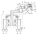
- FIG. 1 is an overall system diagram showing a drive system of a hybrid vehicle to which the regenerative cooperative brake control device of this embodiment is applied.
- the drive system of this hybrid vehicle includes an engine E, a first motor generator MG1 (generator), a second motor generator MG2, an output sprocket OS, and a power split mechanism TM.
- the engine E is a gasoline engine or a diesel engine, and controls a bubble opening degree of a throttle bubble and the like based on a control command from an engine controller 41 described later.
- the first motor generator MG1 and the second motor generator MG2 are synchronous motor generators in which a permanent magnet is embedded in a rotor and a stator coil is wound around a stator.
- the first motor generator MG1 and the second motor generator MG2 are independently controlled by applying a three-phase alternating current generated by the power control unit 43 based on a control command from a motor controller 42 described later.
- Both the motor generators MG1 and MG2 can also operate as electric motors that are driven to rotate by receiving power supplied from the battery 44 (hereinafter, this operation state is referred to as “powering”).
- both the motor generators MG1 and MG2 can function as a generator that generates an electromotive force at both ends of the stator coil to charge the battery 44 (hereinafter, referred to as “the generator 44”). This operating state is called regeneration.)
- the power split mechanism TM is constituted by a simple planetary gear having a sun gear S, a pinion P, a ring gear R, and a pinion carrier PC.
- the connection relationship of the input / output members with respect to the three rotating elements (sun gear S, ring gear R, and pinion carrier PC) of the simple planetary gear will be described.
- the sun gear S is connected to a first motor generator MG1.
- the ring gear R is connected to the second motor generator MG2 and the output sprocket OS.
- An engine E is connected to the pinion carrier PC via an engine damper ED.
- the output sprocket OS is connected to the left and right front wheels via a chain belt CB, a differential (not shown), and a drive shaft.
- the control system of the hybrid vehicle in this embodiment includes an engine controller 41, a motor controller 42, a power control unit 43, a battery 44 (secondary battery), a brake controller 45, and an integrated controller. 46.
- the integrated controller 46 inputs input information from an accelerator opening sensor 47, a vehicle speed sensor 48, an engine speed sensor 49, a first motor generator speed sensor 50, and a second motor generator speed sensor 51. .
- the integrated controller 46 is responsible for managing the energy consumption of the entire vehicle and running the vehicle with the highest efficiency. That is, the integrated controller 46 performs engine operating point control by a control command to the engine controller 41 during acceleration traveling or the like. Further, the integrated controller 46 performs motor generator operating point control by a control command to the motor controller 42 at the time of stopping, running, braking, or the like.
- the integrated controller 46 includes the accelerator opening AP, the vehicle speed VSP, the engine speed Ne, the first motor generator speed N1, and the second motor generator speed N2 from the sensors 47, 48, 49, 50, 51. input. And based on these input information, a predetermined calculation process is performed and the control command by the process result is output to the engine controller 41 and the motor controller 42.
- the integrated controller 46 and the engine controller 41, the integrated controller 46 and the motor controller 42, the integrated controller 46 and the brake controller 45, etc. are connected by bidirectional communication lines 64, 65 and 66, respectively, for information exchange.
- the engine controller 41 outputs, for example, a command for controlling the engine operating point (Ne, Te) to a throttle valve actuator (not shown) in accordance with a target engine torque command or the like from the integrated controller 46.
- the integrated controller 46 calculates a target engine torque command and the like based on the accelerator opening AP from the accelerator opening sensor 47 and the engine speed Ne from the engine speed sensor 49.
- the motor controller 42 calculates a command for controlling the motor operating point (N1, T1) of the first motor generator MG1 in accordance with a target motor generator torque command or the like from the integrated controller 46.
- a command for controlling the motor operating point (N2, T2) of the second motor generator MG2 is calculated according to the target motor generator torque command or the like.
- the motor controller 42 uses information on the battery SOC that indicates the state of charge of the battery 44. Further, the integrated controller 46 obtains the target motor generator torque command and the like based on the motor generator rotational speeds N1 and N2 from the both motor generator rotational speed sensors 50 and 11 by the resolver.
- the power control unit 43 includes a joint box (not shown), a boost converter, a drive motor inverter, and a generator generator inverter.
- Power control unit 43 constitutes a power supply system high voltage system that can supply power to both motor generators MG1 and MG2 with less current.
- a drive motor inverter is connected to the stator coil of the second motor generator MG2.
- a generator generator inverter is connected to the stator coil of the first motor generator MG1.
- the joint box is connected to a battery 44 that is discharged during power running and charged during regeneration.
- the power control unit 43 obtains the effective regenerative torque T (t) and outputs the effective regenerative torque T (t) to the brake controller 45.
- the brake controller 45 includes a front left wheel speed sensor 52, a front right wheel speed sensor 53, a rear left wheel speed sensor 54, a rear right wheel speed sensor 55, a master cylinder pressure sensor 57, and a brake stroke sensor 58. And input information.
- the brake controller 45 performs regenerative brake cooperative control by issuing a control command to the integrated controller 46 and a control command to the brake fluid pressure unit 76 during braking by operating the engine brake or the brake pedal 8a.
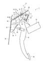
- reference numeral 8 a is a brake pedal that is operated to instruct the braking torque requested by the driver.
- the brake pedal 8 a is provided at the lower part of the pedal arm 8.
- the pedal arm 8 extends substantially in the vertical direction.
- the upper end portion 7 of the pedal arm 8 is supported so as to be rotatable with respect to the vehicle body side member 31.
- the rear end portion of the input rod 35 is connected to the pedal arm 8 in the middle in the vertical direction.
- the brake pedal 8 a is connected to the booster 70 via the input rod 35, and the booster 70 is connected to the master cylinder 74 via the push rod 71.
- the pedaling force resulting from the depression of the brake pedal is input to the booster 70 via the input rod 35.
- the booster 70 boosts the pedal depression force according to the depression amount of the brake pedal 8a, and advances and retracts the pistons 74b and 74c in the master cylinder 74 via the push rod 71.
- Reference numeral 75 denotes a reservoir tank for the control liquid.
- the master cylinder 74 is connected to the wheel cylinders 60 to 63 of each wheel through a pipe line constituting the hydraulic circuit 76.
- a proportional electromagnetic bubble 77 for fluid pressure control is inserted upstream of the conduit.
- FIG. 2 shows a state in which the proportional electromagnetic bubble 77 for fluid pressure control is not energized, and shows a state in which the fluid in the master cylinder 74 is supplied to the wheel cylinders 60 to 63 as it is.
- This proportional electromagnetic bubble 77 for fluid pressure control adjusts the fluid (fluid pressure) supplied from the master cylinder 74 to the wheel cylinders 60 to 63 by the control current from the brake controller 45.
- the conduit includes a brake control pump 78.
- the brake control pump 78 has a suction port connected to the master cylinder 74 and a discharge port communicating with the wheel cylinders 60 to 63.
- the brake control pump 78 increases the cylinder pressure of the wheel cylinders 60 to 63 based on a control command from the brake controller 45.
- a proportional pressure control solenoid valve for pressure increase for ABS control and other controls (hereinafter referred to as a pressure increase solenoid valve)
- a proportional solenoid valve for fluid pressure control (hereinafter referred to as a pressure reducing solenoid valve) may be provided so that the brake fluid pressures of the wheel cylinders 60 to 63 can be individually controlled.
- the master cylinder pressure sensor 57 detects the output pressure of the master cylinder 74 and supplies the detection signal to the brake controller 45. Further, the brake fluid pressure of each wheel cylinder 60 to 63 is detected by the pressure sensor 80, and the detection signal is also supplied to the brake controller 45.
- the vehicle brake device of the present embodiment further includes an invalid stepping mechanism 100A, a pedal retraction inhibiting mechanism 100B, and a pedal urging unit 100C.
- the invalid stepping mechanism 100A brings the at least one hydraulic chamber 74d of the master cylinder 74 into communication with the reservoir tank 75 when the stepping operation position of the brake pedal 8a is a preset invalid stepping region.
- the invalid stepping mechanism 100 ⁇ / b> A is a mechanism that suppresses generation of basic hydraulic pressure by the master cylinder 74 in the invalid stepping region.
- the amount of depression of the brake pedal is from the pedal depression start position to the preset initial depression amount as an invalid stepping region. In this invalid stepping region, the basic fluid by the master cylinder 74 is used. Reduces the generation of pressure.
- the invalid stepping mechanism 100A is a mechanism that invalidates the stroke of the input rod 35 or the push rod 71 with respect to the operation of the brake pedal 8a in the invalid stepping region and prevents the basic hydraulic pressure from being generated in the master cylinder 74.
- the invalid stepping mechanism 100A is set inside the booster device 70, set between the brake pedal 8a and the input rod 35 of the booster device 70 as in the above-mentioned prior art, and inside the master cylinder 74. Configurations such as those to be set can be considered.
- the invalid stepping mechanism 100 ⁇ / b> A when set inside the booster 70 includes a mechanism that suppresses the stroke of the push rod 71 with respect to the stroke of the input rod 35 according to the operation of the brake pedal 8 a in the invalid stepping region, for example.
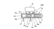
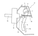
- the master cylinder 74 of the present embodiment is a tandem master cylinder 74 and includes a housing 74a formed in a bottomed cylindrical shape.
- the first and second pistons 74b and 74c are accommodated in the housing 74a so as to be liquid-tight and slidable.
- a first spring 74e is disposed in a first hydraulic pressure chamber 74d formed between the first piston 74b and the second piston 74c.
- a second spring 74g is disposed in a second hydraulic pressure chamber 74f formed between the second piston 74c and the closed end of the housing 74a.
- the second piston 74c is urged toward the opening end side (first piston 74b side) by the second spring 74g, and the first piston 74b is urged toward the opening end side by the first spring 74e.
- one end (opening end side end) of the first piston 74b comes into contact with the tip of the push rod 71 extending from the booster 70 in a pressed state.
- the housing 74a of the master cylinder 74 has a first port 74h for communicating the first hydraulic chamber 74d and the reservoir tank 75, and a second port 74i for communicating the second hydraulic chamber 74f and the reservoir tank 75. And are provided.
- the first port 74h is a first piston located at a first position (return position: illustrated state in FIG. 3) in which the driver's foot is separated from the brake pedal 8a, that is, the brake pedal 8a is not depressed.
- the second piston 74b is disposed at a second position away from the closed end that closes the same port 74h by an invalid stroke distance s in the pressure increasing direction of the first piston 74b (direction on the closed end side: leftward in FIG. 3). .
- the second port 74i has a closed end that closes the second port 74i of the second piston 74c in the first position (return position: the state shown in FIG. 3) as an open end of the second port 74i. (That is, a position immediately before the closed end of the second piston 74c begins to close the opening of the second port 74i).
- a mechanism for configuring the above invalid stroke distance s is an invalid stepping mechanism 100A.
- the invalid stroke distance s is preferably set so that the regenerative brake generates the maximum regenerative braking force when the brake operation state is a predetermined state. Thereby, when the brake operation state becomes a predetermined state, the master cylinder 74 releases the restriction on the generation of the basic hydraulic braking force, and the regenerative brake generates the maximum regenerative braking force.
- the housing 74a of the master cylinder 74 constitutes a third port 74j for communicating the first hydraulic chamber 74d and the oil path Lr constituting the rear wheel system, and the second hydraulic chamber 74f and the front wheel system.
- a fourth port 74k for communicating with the oil path Lf is provided.
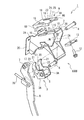
- the pedal retraction inhibiting mechanism 100B is a mechanism that inhibits the retreating of the brake pedal 8a (movement toward the driver's seat) during a frontal collision of the vehicle.
- the pedal reverse restraining mechanism 100B described in Japanese Patent Laid-Open No. 2000-280836 is applied will be described.
- the pedal retraction inhibiting mechanism 100B is provided in a rotation support portion that rotatably supports the brake pedal 8a on the vehicle body side member 31, and when an impact in the vehicle front-rear direction that exceeds a setting is input, The movement support portion is displaced rearward in the vehicle front-rear direction to suppress the backward movement of the brake pedal 8a.
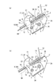
- the pedal bracket 2 is fastened and fixed to the dash lower panel 30 of the dash panel by bolts and nuts (not shown) at a flange portion 2C provided in the front and rear direction of the vehicle.
- the pedal bracket 2 is a member having a substantially U-shaped cross section, and includes a pair of side wall portions 2A and 2A that are spaced apart from each other, and an upper wall portion 2B that connects them above.
- a substantially U-shaped pivot bracket 3 is pivotally supported via a collar 5 with respect to a shaft 4 provided on the pedal bracket 2.
- the pivot bracket 3 is provided with a pedal shaft 6 in front of the shaft 4 in the front-rear direction of the vehicle so as to straddle the opposing side plate portions 3A and 3A of the pivot bracket 3.
- a pedal arm 8 is rotatably supported on the pedal shaft 6 via a collar 7.
- a slide plate 9 is fixed to a lower surface portion of a vehicle body side member 31 such as a dash upper panel that is joined to the upper end of the dash lower panel 30 and extends rearward in the vehicle front-rear direction.
- the slide plate 9 is a substantially flat plate-like member that is superposed and fixed on the upper surface portion of the upper wall portion 2B of the pedal bracket 2.
- the slide plate 9 is formed in a dish shape having a downward flange 9B that covers the upper wall 2B of the pedal bracket 2 on both sides of the upper wall 9A.
- the mounting of the slide plate 9 is specifically as follows. That is, bolt insertion holes 10 and 11 are provided in the upper wall portion 2B of the pedal bracket 2 and the upper wall 9A of the slide plate 9, respectively.
- the slide plate 9 is inserted into the bolt insertion holes 10 and 11 from the lower side of the vehicle body side bracket 32 that is joined to the lower surface of the vehicle body side member 31 such as a dash upper panel at the rear end portion thereof from below the vehicle.
- the bolt 12 is fastened together with the upper wall 2B of the pedal bracket 2 with the fixing plate 13 and the nut 14 provided on the lower surface side of the slide plate 9, that is, the inner lower surface of the upper wall 2B of the pedal bracket 2. is there.
- the bolt insertion hole 10 of the upper wall portion 2B is formed in a long hole shape with the front in the vehicle front-rear direction opened.
- the slide plate 9 is configured to be movable relative to the pedal bracket 2 in the vehicle front-rear direction.
- an upper wall 9A of the slide plate 9 constitute a collision absorbing means for absorbing an impact.
- openings 15 are provided at both side edges of the upper wall 2B of the pedal bracket 2, and holes (openings) 16 are provided at both sides of the front end of the upper wall 9A of the slide plate 9. .
- a protrusion 17 is provided through the opening 15 and the hole 16 so as to project upward from the front end of the side plate 3 ⁇ / b> A of the pivot bracket 3.
- a notch 19 provided at the front end of the protrusion 17 is engaged with the front edge 18 of the hole 16.
- the front edge 18 in the hole 16 at the front end of the slide plate 9 and the notch 19 at the front end of the pivot bracket 3 are engaged as described above. ing. Thereby, the downward rotation of the pivot bracket 3 is restricted, and the depression position of the pedal arm 8 is restricted to a predetermined position. As a result, the pedal arm 8 can be rotated with the pedal shaft 6 as a fulcrum, and a normal master back operation by the booster 70 can be performed via the input rod 35 connected to the pedal arm 8.
- the pedal bracket 2 moves relative to the slide plate 9 in the vehicle longitudinal direction rearward within the length range of the bolt insertion hole 10 formed in the elongated hole.
- the rotation assist pressing portion 20 is formed such that the rear end portion 21 protrudes rearward toward the vehicle body side bracket 32 positioned rearward. As shown in FIG. 6A, the rotation assist pressing portion 20 is an engagement portion between the pivot bracket 3 and the slide plate 9 between the rear end portion 21 and the vehicle body side bracket 32 (L1). Is set slightly larger than the meshing margin (L).
- the rear edge portion 22 of the rotation assist pressing portion 20 is formed in a curved shape as shown in FIG.
- This curved shape is a component force that is input to the rear edge 22 from the slide plate 9 when the slide plate 9 moves forward relative to the pedal bracket 2 and comes into contact with the rear edge 23 of the hole 16. It is formed in a curved shape such that f acts substantially downward.
- the space between the opening 15 and the hole 16 and the rear edge portion 22 of the auxiliary rotation pressing portion 20 (L2) is also larger than the engagement margin (L) of the engaging portion between the pivot bracket 3 and the slide plate 9. The rear edge 23 of the hole 16 abuts after the engagement of the engaging portion has been reliably released.
- a restricting portion 24 is provided.
- the restricting portion 24 receives a force in the direction opposite to the turning direction due to the interference between the pedal arm 8 and the peripheral component 33 when the pivot bracket 3 is turned, the restricting portion 24 moves to the turning auxiliary pressing portion 20. And the rotation in the opposite direction is restricted.
- the restricting portion 24 is set behind the hole portion 16 of the slide plate 9, and the opening portion 15 of the pedal bracket 2 is caused by relative movement of the slide plate 9 when an input in a backward direction exceeding a predetermined load is applied to the pedal bracket 2.
- the slide plate 9 can be moved relative to the bolt insertion hole 10 formed in the shape of the long hole until the opening concealing portion 25 of the slide plate 9 closes the opening 15 of the pedal bracket 2. It is formed in length.
- the pedal arm 8 since the pivot of the pivot bracket 3 is regulated by the slide plate 9 in a normal state, the pedal arm 8 is pivoted with the pedal shaft 6 as a fulcrum. A normal master back operation by the booster device 70 can be performed through the input rod 35 connected to the motor 8.
- the slide plate 9 and the pedal bracket 2 relatively move in the longitudinal direction of the vehicle within the length range of the bolt insertion hole 10.
- the pivot bracket 3 and the slide plate 9 are disengaged from each other, allowing the pivot bracket 3 to rotate, and pivoting the pivot bracket 3 downward and rearward with the shaft 4 as a fulcrum.
- the stepping position 8 is drawn toward the front side in the vehicle front-rear direction. For this reason, even if the booster 70 is moved backward, or the input rod 35 extending from the booster 70 is moved backward due to deformation of the dash lower panel 40 toward the passenger compartment, the stepping position of the pedal arm 8 is shifted backward. It is possible to avoid a sense of incongruity.
- the rotation assist pressing portion 20 is provided on the upper portion of the pivot bracket 3 so as to project upward.
- the rotation assist pressing portion 20 abuts on the vehicle body side bracket 32 as the vehicle body side member 31 when the pivot bracket 3 is rotated, and promotes the rotation of the pivot bracket 3 to the lower rear. For this reason, the pivot bracket 3 can be forcibly rotated downward and rearward.
- the rotation assist pressing portion 20 is set to the rear in the vehicle front-rear direction with respect to the engaging portion between the pivot bracket 3 and the slide plate 9 and protrudes toward the vehicle body side bracket 32 positioned behind the rotation assist pressing portion 20.
- the space between the rear end portion 21 of the rotation assist pressing portion 20 and the vehicle body side bracket 32 is set to be slightly larger than the engagement allowance of the engagement portion. For this reason, when the engagement between the slide plate 9 and the pivot bracket 3 is released at the time of a frontal collision of the vehicle, the rotation auxiliary pressing portion 20 immediately contacts the vehicle body side bracket 32 positioned behind the swift auxiliary pressing portion 20.
- the pivot bracket 3 can be rotated downward and rearward.
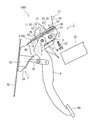
- the pedal urging unit 100C constitutes a mechanism that urges the input rod 35 in the return direction of the brake pedal 8a when the depression operation position of the brake pedal 8a is at least the invalid depression region.
- the pedal urging portion 100 ⁇ / b> C has one end attached to the input rod 35 and the other end attached to the vehicle body side member 31, and the spring force in the return direction of the brake pedal 8 a is applied to the input rod 35.
- An elastic body 82 is provided. In the present embodiment, the other end side of the elastic body 82 is positioned in the return direction of the brake pedal 8a rather than the one end side.
- the input rod 35 is formed with an overhanging portion 81 that projects from the input rod 35 in the outer diameter direction.
- the overhang portion 81 of this embodiment shown in FIG. 8 is an example in which the overhang portion 81 is formed so as to rise upward from the input rod 35, but the overhang direction of the overhang portion 81 may be downward or sideward.
- a first spring latching portion is formed on the overhang portion 81.
- the 1st spring latching part of this embodiment is formed from the notch part 81a open
- the notch 81a of the above embodiment is formed in a wedge shape whose vertical width becomes narrower toward the rear in the vehicle front-rear direction (seat direction).
- tip part of the notch part 81a may be sharp, or may be rounded.
- a second spring latching portion is formed on the vehicle body side member 31 located rearward in the vehicle longitudinal direction with respect to the overhanging portion 81.
- the second spring latching portion of the present embodiment is formed from an opening portion opened in the vehicle body side member 31.
- the elastic body 82 has a coil spring 82a as a main body, and hook portions 82b and 82c as attachment portions are formed at both ends in the longitudinal direction. And one hook part 82b is hooked on the notch part 81a which is said 1st spring latching part, and the other hook part 82c is hooked on a 2nd spring latching part.
- the axis of the coil spring 82a is set to be parallel or substantially parallel to the input rod 35.
- the pedal urging portion 100C even in the invalid stepping region, the spring force of the elastic body 82 generated by the pedal urging portion 100C according to the stroke amount of the input rod 35 is It is added as a pedaling force when the brake pedal 8a is operated. As a result, deterioration of the controllability of the brake pedal 8a is suppressed.
- the necessary deceleration is obtained by controlling the hydraulic pressure in the master cylinder 74 in accordance with the operation of the brake pedal 8a.
- a regenerative cooperative brake system is realized. Therefore, it is necessary to automatically control the hydraulic pressure in accordance with the amount of regenerative torque. Therefore, a certain invalid stepping area where no hydraulic pressure is generated in the master cylinder 74 is added to the pedal operation. Is configured to control deceleration by a regenerative torque and hydraulic automatic control device.
- the pedal urging portion 100C of the present embodiment has the elastic body 82 arranged so as to connect the input rod 35 and the vehicle body side member 31, so that the input rod 35 is displaced even in the axial direction. It is avoided that the elastic body 82 bends. As a result, in the pedal urging portion 100C of the present embodiment, the restriction on the amount of displacement of the input rod 35 in the direction perpendicular to the axis is relaxed compared to the elastic body for reaction force of the prior art.
- the elastic body for reaction force described in the above-mentioned prior art document 1 needs to secure a space for disposing it between the booster and the brake pedal on the entire outer periphery of the input rod. For this reason, it is necessary to move and arrange
- the pedal urging portion 100C of the present embodiment does not need to be disposed between the booster 70 and the brake pedal 8a on the entire outer periphery of the input rod 35, thus avoiding such a problem. I can do it.
- a pedal retraction inhibiting mechanism 100B at the time of collision is provided. That is, when the vehicle collides with the front, the slide plate and the pedal bracket move relative to each other in the vehicle front-rear direction to disengage the pivot bracket from the slide plate, allowing the pivot bracket to rotate, Since the pivot bracket is pivoted downward and rearward with the shaft as a fulcrum, the stepping position of the pedal arm 8 is pulled forward in the vehicle longitudinal direction, so that the booster 70 moves backward or the dash lower panel is on the vehicle compartment side. Even if the push rod 71 that is deformed and extends from the booster 70 moves backward, it can be avoided that the depression position of the pedal arm 8 is shifted backward and a sense of incongruity is generated.
- a pivot assist pressing portion that abuts at least one of the vehicle body side member or the slide plate when the pivot bracket pivots and promotes pivoting rearward and rearward of the pivot bracket is disposed above the pivot bracket. And the pivot bracket is forcibly pivoted downward and rearward because the pivot bracket pressing opening is provided in the upper wall of the pedal bracket and the slide plate. be able to.
- the pedal retraction inhibiting mechanism 100B is activated to inhibit the brake pedal 8a from retreating, so that the input rod 35 needs to be displaced in the axial direction.
- the operation of the pedal retraction inhibiting mechanism 100B may be hindered. That is, when a brake device having a mechanism for suppressing the reverse amount of the brake pedal 8a at the time of a collision is combined with this as a measure for reducing the influence on the passenger at the time of the collision accident, a pedal reaction force is generated in the invalid stepping area. There is a concern that the function of the pedal retraction inhibiting mechanism 100B may be hindered depending on the elastic body installation method.
- the attachment method of the elastic body 82 by devising the attachment method of the elastic body 82, it functions as an urging means at the time of pedal operation during normal operation, but as shown in FIG. It is possible not to disturb its function. Further, when the rear end portion of the input rod 35 swings when the pedal retraction suppressing mechanism is operated, the hook portion 82b of the elastic body 82 is only hooked on the notch portion 81a constituting the first spring latching portion. The hook part 82b is easily detached from the notch part 81a which is the first spring latching part.
- the notch portion 81a has a wedge shape with an upper portion and a lower portion inclined. Therefore, when the rear end portion of the input rod 35 is displaced in the vertical direction, one of the upper portion and the lower portion of the notch portion formed by the notch portion 81a. It becomes easier to come off.
- the present embodiment by attaching one end portion of the elastic body 82 to the input rod 35, it is possible to prevent the moment that promotes the forward movement of the brake pedal 8a from being applied to the pedal arm 8. .
- the present embodiment is applicable to any system that does not generate the master cylinder 74 hydraulic pressure in a certain amount of pedal operation, which has an invalid stroke, regardless of the structure of the booster 70.
- the booster 70 may be of any type such as a negative pressure booster, a hydraulic booster, and an electric booster. Further, the pedal retreat prevention mechanism can be applied regardless of its structure and mechanism.
- the vehicle brake device moves the input rod 35 toward the brake pedal 8a when the invalid stepping mechanism 100A, the pedal retraction inhibiting mechanism 100B, and the stepping operation position of the brake pedal 8a are at least the invalid stepping region.
- a pedal urging portion 100C for urging the pedestal.
- the pedal urging portion 100C has one end portion attached to the input rod 35 and the other end portion attached to the vehicle body side member 31, and an elastic body 82 that applies a spring force in the return direction of the brake pedal 8a to the input rod 35.
- the reaction force generated by the elastic body 82 acts on the pedal, so that even when the stepping operation position of the brake pedal 8a is in the invalid stepping region, it is possible to reduce the inhibition of the pedal swinging. .
- the elastic body 82 can be prevented from restricting the reverse suppression of the brake pedal 8a when the pedal reverse suppression mechanism 100B is operated. It becomes possible to make the suppression mechanism 100B act effectively.
- the elastic body 82 when the elastic body 82 is attached to the pedal arm 8 (see FIG. 10), the elastic body 82 restricts the rotation when the brake pedal 8a is rotated by the operation of the pedal retraction inhibiting mechanism 100B. There is a possibility that a problem may occur, but in the present embodiment, this can be avoided.
- One end of the elastic body 82 is attached to the input rod 35 so as to be capable of rotational displacement at least in the vertical direction.
- the input rod 35 is provided with a projecting portion 81 projecting in the outer diameter direction, and a notch portion 81a is formed in the projecting portion 81, and one end portion of the elastic body 82 is connected to the notch portion 81a. Hook it.
- the one end of the elastic body 82 is easily disconnected from the input rod 35. Since the elastic body 82 is detached from the input rod, there is no reaction force that restricts the swing of the pedal and the movable portion (input rod 35) by the added elastic body 82. As a result, the pedal retreat prevention mechanism can be more effectively operated.
- the notch 81a has a shape in which the vertical width decreases as it goes rearward in the vehicle front-rear direction. That is, it has a wedge shape. It is preferable to form the notch deeper in the direction in which it is urged by the elastic body 82. According to this configuration, when the input rod 35 swings more than set in advance, one end of the elastic body 82 connected to the input rod 35 is easily detached from the input rod 35.
- Japanese Patent Application No. 2013-027300 filed on Feb. 15, 2013
- the present application claims priority form part of the present disclosure by reference.
Landscapes
- Engineering & Computer Science (AREA)
- Transportation (AREA)
- Mechanical Engineering (AREA)
- Physics & Mathematics (AREA)
- General Physics & Mathematics (AREA)
- Automation & Control Theory (AREA)
- Braking Elements And Transmission Devices (AREA)
- Mechanical Control Devices (AREA)
Abstract
Description
そして上記車両用ブレーキ装置では、上記スプリングの作用によって、ブレーキペダルの踏込み量が所定以上のペダル踏込み量となるまでは、上記ブレーキペダルの踏込み操作に伴う上記スリーブの進退が、上記インプットロッドに、さらにはブレーキブースタに伝達されない機構となっている。またこのとき、上記スプリングの圧縮変形によって所定のペダル反力が発生する。
本発明は、上記のような点に鑑みてなされたもので、無効踏込み領域を有する車両用ブレーキ装置において、ペダル反力発生用の弾性体を設けてもインプットロッドの軸直方向への変位をより許容可能にすることを目的とする。
(構成)
本発明に基づく車両用ブレーキ装置を、回生協調ブレーキ制御装置を装備したハイブリッド車に適用する場合を例に挙げて説明する。
まず、ハイブリッド車の駆動系構成を説明する。
図1は、本実施形態の回生協調ブレーキ制御装置を適用するハイブリッド車の駆動系を示す全体システム図である。
このハイブリッド車の駆動系は、図1に示すように、エンジンEと、第1モータジェネレータMG1(発電機)と、第2モータジェネレータMG2と、出力スプロケットOS、動力分割機構TMと、を有する。
上記エンジンEは、ガソリンエンジンやディーゼルエンジンであり、後述するエンジンコントローラ41からの制御指令に基づいて、スロットルバブルのバブル開度等を制御する。
上記両モータジェネレータMG1,MG2は、バッテリ44からの電力の供給を受けて回転駆動する電動機として動作することもできる(以下、この動作状態を「力行」と呼ぶ。)。また、上記両モータジェネレータMG1,MG2は、ロータが外力により回転している場合には、ステータコイルの両端に起電力を生じさせる発電機として機能してバッテリ44を充電することもできる(以下、この動作状態を回生と呼ぶ。)。
その単純遊星歯車の3つの回転要素(サンギヤS、リングギヤR、ピニオンキャリアPC)に対する入出力部材の連結関係について説明する。上記サンギヤSには、第1モータジェネレータMG1を連結する。上記リングギヤRには、第2モータジェネレータMG2と出力スプロケットOSとを連結する。上記ピニオンキャリアPCには、エンジンダンパEDを介してエンジンEを連結する。なお、上記出力スプロケットOSは、チェーンベルトCBや図外のディファレンシャルやドライブシャフトを介して左右前輪に連結する。
本実施形態におけるハイブリッド車の制御系は、図1に示すように、エンジンコントローラ41と、モータコントローラ42と、パワーコントロールユニット43と、バッテリ44(二次電池)と、ブレーキコントローラ45と、統合コントローラ46と、を有して構成される。
統合コントローラ46は、アクセル開度センサ47と、車速センサ48と、エンジン回転数センサ49と、第1モータジェネレータ回転数センサ50と、第2モータジェネレータ回転数センサ51と、から入力情報を入力する。
上記モータコントローラ42は、統合コントローラ46からの目標モータジェネレータトルク指令等に応じ、第1モータジェネレータMG1のモータ動作点(N1,T1)を制御する指令を演算する。また独立して、上記目標モータジェネレータトルク指令等に応じ、第2モータジェネレータMG2のモータ動作点(N2,T2)を制御する指令を演算する。そして、これら演算した指令をパワーコントロールユニット43へ出力する。なお、モータコントローラ42は、バッテリ44の充電状態をあらわすバッテリSOCの情報を用いる。また、統合コントローラ46は、レゾルバによる両モータジェネレータ回転数センサ50,11からのモータジェネレータ回転数N1,N2に基づき、上記目標モータジェネレータトルク指令等を求める。
上記ブレーキコントローラ45には、前左車輪速センサ52と、前右車輪速センサ53と、後左車輪速センサ54と、後右車輪速センサ55と、マスターシリンダ圧センサ57と、ブレーキストロークセンサ58と、から入力情報を入力する。そして、この上記ブレーキコントローラ45は、エンジンブレーキやブレーキペダル8aの操作による制動時、統合コントローラ46への制御指令とブレーキ液圧ユニット76への制御指令を出すことで回生ブレーキ協調制御を行う。
次に、本実施形態の車両用ブレーキ装置を適用する制動系の液圧ブレーキ装置の基本構成について、図2を参照して説明する。
図2中、符号8aは、運転者が要求する制動トルクを指示するために操作されるブレーキペダルである。そのブレーキペダル8aは、ペダルアーム8の下部に設けられている。ペダルアーム8は、略上下方向に延在する。そのペダルアーム8の上端部7は、車体側部材31に対して回動可能な状態で支持されている。そのペダルアーム8の上下方向中途位置にインプットロッド35の後端部が連結している。これによってブレーキペダル8aは、インプットロッド35を介して倍力装置70に連結し、倍力装置70は、プッシュロッド71を介してマスターシリンダ74に連結している。これにより、ブレーキペダル踏込みによる踏力は、インプットロッド35を介して倍力装置70に入力される。そして、倍力装置70は、ブレーキペダル8aの踏込み量に応じたペダル踏力を倍力し、上記プッシュロッド71を介して、マスターシリンダ74内のピストン74b、74cを進退させる。符号75は制御液体用のリザーバタンクである。
無効踏込み機構100Aは、ブレーキペダル8aの踏込み操作位置が予め設定した無効踏込み領域の場合に、マスターシリンダ74の少なくとも一つの液圧室74dをリザーバタンク75に連通した状態とする。無効踏込み機構100Aは、上記無効踏込み領域では、マスターシリンダ74による基礎液圧の発生を抑制する機構である。本実施形態の無効踏込み機構100Aでは、ブレーキペダルの踏込み量が、ペダル踏込み開始位置から予め設定した初期踏込み量までの間を無効踏込み領域とし、この無効踏込み領域では、上記マスターシリンダ74による基礎液圧の発生を抑制させる。
ここで、本実施形態のマスターシリンダ74は、図3に示すように、タンデム式のマスターシリンダ74であり、有底筒状に形成されたハウジング74aを備える。そのハウジング74a内に、液密かつ摺動可能に並べて第1および第2ピストン74b,74cが収納されている。その第1ピストン74bと第2ピストン74cとの間に形成される第1液圧室74d内に、第1スプリング74eが配設される。第2ピストン74cとハウジング74aの閉塞端との間に形成される第2液圧室74f内に、第2スプリング74gが配設されている。これにより、第2ピストン74cは第2スプリング74gによって開口端側(第1ピストン74b側)に付勢され、第1ピストン74bは第1スプリング74eによって開口端側に付勢される。この結果、第1ピストン74bの一端(開口端側端)が、倍力装置70から延びるプッシュロッド71の先端に押圧された状態で当接する。
第1ポート74hは、ブレーキペダル8aから運転者の足が離れている状態すなわちブレーキペダル8aが踏み込まれていない状態である第1位置(戻り位置:図3の図示状態)に位置する第1ピストン74bの同ポート74hを閉塞する閉塞端から、第1ピストン74bの増圧方向(閉塞端側の方向:図3において左方向)に無効ストローク距離sだけ離れた第2位置に配設されている。第2ポート74iは、第1ピストン74bと同様に第1位置(戻り位置:図3の図示状態)にある第2ピストン74cの第2ポート74iを閉塞する閉塞端が第2ポート74iの開口端に一致する位置(すなわち第2ピストン74cの閉塞端が第2ポート74iの開口を塞ぎ始める直前位置)に配設されている。
さらに、マスターシリンダ74のハウジング74aは、第1液圧室74dと後輪系統を構成する油経路Lrとを連通するための第3ポート74jと、第2液圧室74fと前輪系統を構成する油経路Lfとを連通するための第4ポート74kとが設けられている。
ペダル後退抑止機構100Bは、車両の前方衝突時におけるブレーキペダル8aの後退(運転席側への移動)を抑止する機構である。本実施形態では、特開2000-280836号に記載のペダル後退抑止機構100Bを適用した場合の例で説明する。
すなわち、ペダル後退抑止機構100Bは、ブレーキペダル8aを車体側部材31に回動可能に支持する回動支持部に設けられていて、設定以上の車両前後方向の衝撃が入力されると、上記回動支持部が車両前後方向後方に変位することで、ブレーキペダル8aの後退を抑える。
ペダルブラケット2が、車両前後方向前方に設けたフランジ部2Cでダッシュパネルのダッシュロアパネル30に図外のボルト・ナットにより締結固定する。このペダルブラケット2は、断面略コ字状の部材であって、離間して配置される一対の側壁部2A,2Aと、これらをその上方で連結する上壁部2Bとからなる。
また略コ字状のピボットブラケット3が、ペダルブラケット2に設けたシャフト4に対しカラー5を介して回転可能に軸支されている。そのピボットブラケット3には、前記シャフト4よりも車両前後方向前方に、そのピボットブラケット3の対向する側板部3A,3Aに跨るようにペダルシャフト6が設けられている。そのペダルシャフト6に、ペダルアーム8が同じくカラー7を介して回動自在に軸支されている。
そのスライドプレート9の取り付けは、具体的には次の通りである。すなわち、前記ペダルブラケット2の上壁部2B及びスライドプレート9の上壁9Aにボルト挿通孔10,11が各々設けられている。そして、そのスライドプレート9は、その後端部で、ダッシュアッパパネル等の車体側部材31の下面に接合配置された車体側ブラケット32の下面に対し前記各ボルト挿通孔10,11に車両下方から挿通したボルト12と、前記スライドプレート9の下面側、つまりペダルブラケット2の上壁部2Bの内側下面に設けた固定プレート13とナット14とで前記ペダルブラケット2の上壁部2Bと共に締結固定してある。
また、前記ペダルブラケット2の上壁部2Bの両側縁部には開口部15を設けると共に、前記スライドプレート9の上壁9A前端部の両側部に孔部(開口部)16が設けられている。その開口部15及びその孔部16に、ピボットブラケット3の側板部3Aの前端部に上方に突設して設けた突出部17が挿通されている。そして、その孔部16の前縁部18に、その突出部17の前端部に設けた切欠部19を係合させてある。
そして、車両の前面衝突時にあっては、前記長孔に形成したボルト挿通孔10の長さ範囲でペダルブラケット2がスライドプレート9に対して車両前後方向後方に相対的に移動する。この相対移動により、ピボットブラケット3の突出部17とスライドプレート9との係合が外れて、ピボットブラケット3の回動を許容し、突出部17がスライドプレート9の孔部16の後縁23で前方に押される。これにより、前記シャフト4を支点としてそのピボットブラケット3を後下方に回動させ、これによりシャフト4の後退移動に伴いペダルシャフト6が図7に示すように斜め後ろ下方に移動する。結果、ペダルアーム8はインプットロッド35との連結点を中心に図7の時計回り方向に回動し、ペダルアーム8の踏込み位置を車両前後方向前方側へ引き寄せる。
また本実施形態では、前述の突出部17は、ピボットブラケット3の回動時に前記車体側部材31に設けた車体側ブラケット32と当接して、前記ピボットブラケット3の下後方への回動を促進する回動補助押圧部20を兼ねている。
この回動補助押圧部20は、後方に位置する車体側ブラケット32へ向けて後端部21が後方に突出して形成される。この回動補助押圧部20は、図6(a)に示すように、後端部21と前記車体側ブラケット32との間(L1)を、前記ピボットブラケット3とスライドプレート9との係合部の噛み合い代(L)よりも若干大きめに設定してある。
以上の実施形態の構造によれば、通常の状態ではスライドプレート9によって、ピボットブラケット3の回動を規制してあるため、ペダルシャフト6を支点としてペダルアーム8を回動して、そのペダルアーム8に連結したインプットロッド35を介して、倍力装置70による通常のマスターバック作動を行わせることができる。
さらに、回動補助押圧部20を、ピボットブラケット3の上部に車両上方に向けて突設してある。回動補助押圧部20は、ピボットブラケット3の回動時に前記車体側部材31としての車体側ブラケット32と当接して、そのピボットブラケット3の下後方への回動を促進する。このため、ピボットブラケット3を強制的に下後方に向けて回動させることができる。
しかも、回動補助押圧部20の後縁部22を、スライドプレート9がペダルブラケット2に対して相対的に前方に移動して孔部16の後縁23と当接した際、その後縁部22にスライドプレート9から入力する分力fが略下方向に作用するような湾曲形状に形成してある、このため、より確実にピボットブラケット3を下後方に向けて、回動させることができる。
なお、上記説明では、ペダルブラケット2をダッシュアッパパネルの下面部に設けた車体側ブラケット32に固定するようにした例を示した。これに限らず、ダッシュロアパネル30の上後方に位置する、例えば車幅方向に延在するステアリングメンバなどの車体側部材に固定するようにしても良い。
ペダル付勢部100Cは、ブレーキペダル8aの踏込み操作位置が少なくとも上記無効踏込み領域の場合に、上記インプットロッド35をブレーキペダル8a戻り方向に付勢する機構を構成する。ペダル付勢部100Cは、図2に示すように、一端部を上記インプットロッド35に取り付け且つ他端部を車体側部材31に取り付けて、ブレーキペダル8a戻り方向のばね力を上記インプットロッド35に付与する弾性体82を備える。本実施形態では、上記弾性体82の上記一端部側よりも他端部側がブレーキペダル8a戻り方向に位置する。
上記弾性体82は、コイルばね82aを本体とし、その長手方向両端部にそれぞれ取り付け部としてのフック部82b、82cが形成されている。そして、一方のフック部82bを上記第1ばね掛止部である切欠き部81aに引っ掛けると共に、他方のフック部82cを第2ばね掛止部に引っ掛ける。
なお、上記コイルばね82aの軸は、インプットロッド35と平行若しくは略平行となるように設定しておく。
運転者がブレーキペダル8aを踏み込むと、その踏込み量に連動してインプットロッド35がマスターシリンダ74側にストロークし、それに応じてプッシュロッド71もマスターシリンダ74内に向けてストロークする。このとき、ブレーキペダル8aの踏込み操作位置が無効踏込み領域の場合には、マスターシリンダ74の液圧室の少なくとも一つがリザーバタンク75に連通してマスターシリンダ74は基礎液圧を発生しない状態となっている。
ここで、ブレーキペダル8a操作時の踏力は、ペダル装置や倍力装置70のもつ反力と、マスターシリンダ74内に発生する液圧反力とによって形成され、この踏力とストロークのバランスがコントロール性を向上させるのには重要である。しかし、上記のように無効踏込み領域を付加した場合、その無効踏込み領域においてはマスターシリンダ74の内圧がゼロないしは低下するためペダル踏力が減少してしまい、コントロール性が悪くなってしまう。
ここで、通常のブレーキシステムにおいてはブレーキペダル8a操作に応じてマスターシリンダ74内の液圧を制御することで必要な減速度を得ているが、本実施形態では、回生協調ブレーキシステムを実現するためには回生トルク量に応じて液圧を自動制御する必要があるため、ペダル操作に対してマスターシリンダ74内の液圧が発生しないある一定の上記無効踏込み領域を付加し、その無効踏込み領域においては回生トルクと液圧自動制御装置によって減速度を制御するように構成する。
またペダル後退抑制機構作動時にインプットロッド35の後端部が揺動すると、弾性体82のフック部82bを第1ばね掛止部を構成する切欠き部81aに引っ掛けてあるだけであるので、当該フック部82bが第1ばね掛止部である切欠き部81aから外れやすくなっている。特に切欠き部81aは、上部及び下部が傾斜した楔状となっているので、インプットロッド35の後端部が上下方向に変位すると、切欠き部81aで形成される切欠きの上部及び下部の一方の傾斜が強くなって、より外れやすくなる。
ここで、本実施形態において、倍力装置70の構造を問わず、無効ストロークを持つことである一定量のペダル操作におけるマスターシリンダ74液圧を発生させない全てのシステムにおいて適用可能である。倍力装置70は、負圧ブースター、油圧ブースター、電動ブースター等の種類は問わない。また、ペダル後退防止機構についてもその構造、仕組みは問わずに適用可能である。
(1)車両用ブレーキ装置は、無効踏込み機構100Aと、ペダル後退抑止機構100Bと、上記ブレーキペダル8aの踏込み操作位置が少なくとも上記無効踏込み領域の場合に、上記インプットロッド35をブレーキペダル8a戻り方向に付勢するペダル付勢部100Cとを備える。上記ペダル付勢部100Cは、一端部を上記インプットロッド35に取り付けると共に他端部を車体側部材31に取り付けて、ブレーキペダル8a戻り方向のばね力を上記インプットロッド35に付与する弾性体82を備える。
この構成によれば、弾性体82が発生する反力がペダルに作用することによって、ブレーキペダル8aの踏込み操作位置が上記無効踏込み領域の場合でも、ペダルの揺動が阻害されるのを低減できる。
ここで、上記弾性体82をペダルアーム8に取り付ける場合には(図10参照)、ペダル後退抑止機構100Bの作動によりブレーキペダル8aが回転する際に、弾性体82がこの回転を規制してしまう不具合が発生するおそれがあるが、本実施形態ではこれを回避可能となる。
これによって、弾性体82のばね力による、インプットロッド35の軸直向の揺動が阻害さる量を低減して、ペダル後退抑止機構100Bの作用時にペダルの揺動が阻害されることを更に低減する。この結果、ペダル後退防止機構を更に効果的に作用させることが可能となる。
この構成によれば、ペダル後退抑止機構100B作用時に、インプットロッド35が揺動した際に、弾性体82の一端部がインプットロッド35との接続が容易に外れるようになる。弾性体82がインプットロッドから外れることで、追加した弾性体82によるペダル及び可動部位(インプットロッド35)の揺動を規制する反力が全くなくなる。この結果、ペダル後退防止機構がさらに効果的に作用させることが可能となる。
この構成によれば、予め設定した以上にインプットロッド35が揺動した場合に、インプットロッド35に接続していた弾性体82の一端部が、インプットロッド35から容易に外れるようになる。
以上、本願が優先権を主張する、日本国特許出願2013-027300(2013年2月15日出願)の全内容は、参照により本開示の一部をなす。
ここでは、限られた数の実施形態を参照しながら説明したが、権利範囲はそれらに限定されるものではなく、上記の開示に基づく各実施形態の改変は当業者にとって自明なことである。
3 ピボットブラケット
6 ペダルシャフト
8 ペダルアーム
8a ブレーキペダル
35 インプットロッド
40 ダッシュロアパネル
70 倍力装置
71 プッシュロッド
74 マスターシリンダ
75 リザーバタンク
81 張出部
81a 切欠き部
82 弾性体
82b フック部
100A 無効踏込み機構
100B ペダル後退抑止機構
100C ペダル付勢部
s 無効ストローク距離(無効踏込み領域相当)
Claims (4)
- ブレーキペダルと、上記ブレーキペダルが設けられると共に車体側部材に対し回動可能に支持されるペダルアームと、
上記ペダルアームに連結し上記ブレーキペダルの踏込み操作に連動して進退するインプットロッドと、
上記インプットロットの進退が倍力装置を介して伝達されるマスターシリンダと、
ブレーキペダルの踏込み操作位置が予め設定した無効踏込み領域の場合に、マスターシリンダの少なくとも一つの液圧室をリザーバタンクに連通させた状態とする無効踏込み機構と、
上記ペダルアームの車体側部材への支持部分に対し設定荷重以上の車両前後方向の衝撃が入力されると、上記ブレーキペダルの車両前後方向後方への移動を抑止するペダル後退抑止機構と、
上記ブレーキペダルの踏込み操作位置が少なくとも上記無効踏込み領域の場合に、上記インプットロッドをブレーキペダル戻り方向に付勢するペダル付勢部とを備え、
上記ペダル付勢部は、一端部を上記インプットロッドに取り付けると共に他端部を車体側部材に取り付けて、上記インプットロッドにブレーキペダル戻り方向のばね力を付与する弾性体を備えることを特徴とする車両用ブレーキ装置。 - 上記弾性体の一端部は、上記インプットロッドに対し、少なくとも上下方向へ回転変位可能に取付けられていることを特徴とする請求項1に記載した車両用ブレーキ装置。
- 上記インプットロッドに外径方向に張り出す張出部を設けると共に、その張出部に切欠き部を形成し、その切欠き部に対し弾性体の一端部を引っ掛けることで、弾性体の一端部を上記インプットロッドに取り付けたことを特徴とする請求項1又は請求項2に記載した車両用ブレーキ装置。
- 上記切欠き部の切欠き形状が楔形状であることを特徴とする請求項3に記載した車両用ブレーキ装置。
Priority Applications (6)
| Application Number | Priority Date | Filing Date | Title |
|---|---|---|---|
| JP2015500007A JP5861801B2 (ja) | 2013-02-15 | 2013-12-26 | 車両用ブレーキ装置 |
| MX2015010457A MX341009B (es) | 2013-02-15 | 2013-12-26 | Dispositivo de freno del vehiculo. |
| RU2015136543/11A RU2587665C1 (ru) | 2013-02-15 | 2013-12-26 | Тормозное устройство транспортного средства |
| CN201380073122.7A CN104995069B (zh) | 2013-02-15 | 2013-12-26 | 车辆用制动装置 |
| US14/767,495 US10005435B2 (en) | 2013-02-15 | 2013-12-26 | Vehicle brake device |
| EP13875293.6A EP2957471B1 (en) | 2013-02-15 | 2013-12-26 | Vehicle brake device |
Applications Claiming Priority (2)
| Application Number | Priority Date | Filing Date | Title |
|---|---|---|---|
| JP2013-027300 | 2013-02-15 | ||
| JP2013027300 | 2013-02-15 |
Publications (1)
| Publication Number | Publication Date |
|---|---|
| WO2014125551A1 true WO2014125551A1 (ja) | 2014-08-21 |
Family
ID=51353587
Family Applications (1)
| Application Number | Title | Priority Date | Filing Date |
|---|---|---|---|
| PCT/JP2013/007624 WO2014125551A1 (ja) | 2013-02-15 | 2013-12-26 | 車両用ブレーキ装置 |
Country Status (8)
| Country | Link |
|---|---|
| US (1) | US10005435B2 (ja) |
| EP (1) | EP2957471B1 (ja) |
| JP (1) | JP5861801B2 (ja) |
| CN (1) | CN104995069B (ja) |
| MX (1) | MX341009B (ja) |
| MY (1) | MY156396A (ja) |
| RU (1) | RU2587665C1 (ja) |
| WO (1) | WO2014125551A1 (ja) |
Cited By (1)
| Publication number | Priority date | Publication date | Assignee | Title |
|---|---|---|---|---|
| US20150158467A1 (en) * | 2012-04-04 | 2015-06-11 | Toyoda Iron Works Co., Ltd. | Connecting pin assembly support fixture |
Families Citing this family (5)
| Publication number | Priority date | Publication date | Assignee | Title |
|---|---|---|---|---|
| CN104290665B (zh) * | 2014-09-26 | 2016-07-13 | 广东东箭汽车用品制造有限公司 | 车辆及其半自动脚踏装置 |
| JP6536457B2 (ja) * | 2016-04-06 | 2019-07-03 | 株式会社デンソー | 発電制御装置 |
| US10108218B2 (en) * | 2016-05-25 | 2018-10-23 | Fontaine Modification Company | Brake assembly for retrofitting a motor vehicle with a dual-position brake system |
| CN110549999B (zh) * | 2018-05-30 | 2021-08-27 | 上海海拉电子有限公司 | 一种用于车辆的油门踏板系统 |
| JP2021091345A (ja) * | 2019-12-12 | 2021-06-17 | トヨタ自動車株式会社 | ブレーキマスタシリンダユニットの取り付け構造 |
Citations (6)
| Publication number | Priority date | Publication date | Assignee | Title |
|---|---|---|---|---|
| JPS6016227U (ja) * | 1983-07-05 | 1985-02-04 | 豊田鉄工株式会社 | 操作ペダル装置 |
| JPH0717371A (ja) | 1990-11-13 | 1995-01-20 | Bendix Europ Services Technic | 空気圧ブレーキブースタ |
| JPH09254821A (ja) * | 1996-03-25 | 1997-09-30 | Toyota Motor Corp | 車両用ペダル支持構造 |
| JPH10175568A (ja) * | 1996-12-19 | 1998-06-30 | Toyota Motor Corp | 車両用ペダル支持構造 |
| JP2000280836A (ja) | 1999-03-30 | 2000-10-10 | Toyoda Gosei Co Ltd | 自動車用ウェザストリップ |
| JP2006264632A (ja) * | 2005-03-25 | 2006-10-05 | Advics:Kk | ブレーキ操作入力装置 |
Family Cites Families (14)
| Publication number | Priority date | Publication date | Assignee | Title |
|---|---|---|---|---|
| US2809725A (en) * | 1953-10-19 | 1957-10-15 | Kelsey Hayes Co | Variable ratio brake lever |
| US2805550A (en) * | 1954-06-28 | 1957-09-10 | Kelsey Hayes Co | Booster brake mechanism |
| US3219775A (en) * | 1963-04-12 | 1965-11-23 | Gen Motors Corp | Brake pedal switch actuating mechanism |
| US4458490A (en) * | 1982-09-27 | 1984-07-10 | General Motors Corporation | Dual power brake booster and method of generating brake actuating pressure |
| DE19604134B4 (de) * | 1996-02-06 | 2004-11-11 | Robert Bosch Gmbh | Verfahren und Vorrichtung zur Steuerung der Bremsanlage von Kraftfahrzeugen mit elektrischem Antrieb |
| JP3781864B2 (ja) * | 1997-04-21 | 2006-05-31 | 日産自動車株式会社 | 自動車のブレーキペダル装置 |
| RU2178366C2 (ru) * | 2000-04-14 | 2002-01-20 | Ульяновский государственный технический университет | Устройство для управления тормозами транспортного средства |
| JP3896779B2 (ja) * | 2000-09-14 | 2007-03-22 | 日産自動車株式会社 | 自動車のブレーキペダル装置 |
| JP4296991B2 (ja) * | 2004-06-08 | 2009-07-15 | 株式会社アドヴィックス | 車両用ブレーキ装置 |
| US20050269875A1 (en) | 2004-06-08 | 2005-12-08 | Kazuya Maki | Vehicle brake device |
| RU63296U1 (ru) * | 2006-11-23 | 2007-05-27 | Открытое акционерное общество "Ульяновский автомобильный завод" | Устройство для управления сцеплением |
| CN101508282A (zh) * | 2009-03-06 | 2009-08-19 | 同济大学 | 用于车辆线控电液复合制动的制动阀及其控制方法 |
| JP5200092B2 (ja) * | 2010-11-17 | 2013-05-15 | 本田技研工業株式会社 | 車両用ブレーキシステム及びその入力装置 |
| JP5691453B2 (ja) * | 2010-12-03 | 2015-04-01 | 日産自動車株式会社 | 電動車両のブレーキ制御装置 |
-
2013
- 2013-12-26 RU RU2015136543/11A patent/RU2587665C1/ru active
- 2013-12-26 JP JP2015500007A patent/JP5861801B2/ja active Active
- 2013-12-26 US US14/767,495 patent/US10005435B2/en active Active
- 2013-12-26 MX MX2015010457A patent/MX341009B/es active IP Right Grant
- 2013-12-26 MY MYPI2015702598A patent/MY156396A/en unknown
- 2013-12-26 CN CN201380073122.7A patent/CN104995069B/zh active Active
- 2013-12-26 EP EP13875293.6A patent/EP2957471B1/en active Active
- 2013-12-26 WO PCT/JP2013/007624 patent/WO2014125551A1/ja active Application Filing
Patent Citations (6)
| Publication number | Priority date | Publication date | Assignee | Title |
|---|---|---|---|---|
| JPS6016227U (ja) * | 1983-07-05 | 1985-02-04 | 豊田鉄工株式会社 | 操作ペダル装置 |
| JPH0717371A (ja) | 1990-11-13 | 1995-01-20 | Bendix Europ Services Technic | 空気圧ブレーキブースタ |
| JPH09254821A (ja) * | 1996-03-25 | 1997-09-30 | Toyota Motor Corp | 車両用ペダル支持構造 |
| JPH10175568A (ja) * | 1996-12-19 | 1998-06-30 | Toyota Motor Corp | 車両用ペダル支持構造 |
| JP2000280836A (ja) | 1999-03-30 | 2000-10-10 | Toyoda Gosei Co Ltd | 自動車用ウェザストリップ |
| JP2006264632A (ja) * | 2005-03-25 | 2006-10-05 | Advics:Kk | ブレーキ操作入力装置 |
Non-Patent Citations (1)
| Title |
|---|
| See also references of EP2957471A4 * |
Cited By (2)
| Publication number | Priority date | Publication date | Assignee | Title |
|---|---|---|---|---|
| US20150158467A1 (en) * | 2012-04-04 | 2015-06-11 | Toyoda Iron Works Co., Ltd. | Connecting pin assembly support fixture |
| US9499138B2 (en) * | 2012-04-04 | 2016-11-22 | Toyoda Iron Works Co., Ltd. | Connecting pin assembly support fixture |
Also Published As
| Publication number | Publication date |
|---|---|
| US10005435B2 (en) | 2018-06-26 |
| JPWO2014125551A1 (ja) | 2017-02-02 |
| EP2957471B1 (en) | 2017-02-15 |
| CN104995069B (zh) | 2016-10-12 |
| RU2587665C1 (ru) | 2016-06-20 |
| MX341009B (es) | 2016-08-03 |
| MY156396A (en) | 2016-02-15 |
| EP2957471A4 (en) | 2016-05-25 |
| CN104995069A (zh) | 2015-10-21 |
| MX2015010457A (es) | 2015-10-26 |
| JP5861801B2 (ja) | 2016-02-16 |
| EP2957471A1 (en) | 2015-12-23 |
| US20160031422A1 (en) | 2016-02-04 |
Similar Documents
| Publication | Publication Date | Title |
|---|---|---|
| JP5861801B2 (ja) | 車両用ブレーキ装置 | |
| KR102187995B1 (ko) | 브레이크 제어 장치 | |
| JP5960461B2 (ja) | ブレーキ装置 | |
| EP2418132B1 (en) | Brake device for vehicle | |
| JP5411118B2 (ja) | 車両用ブレーキ装置 | |
| JP5815183B2 (ja) | 車両用ブレーキ装置 | |
| JP5406109B2 (ja) | 回生協調ブレーキ用ストロークシミュレータ | |
| JP2007022105A (ja) | 車両用制動装置 | |
| JP6167387B2 (ja) | ハイブリッド式作業車両 | |
| JP5566873B2 (ja) | 車両用ブレーキ装置 | |
| JP5997565B2 (ja) | ブレーキ制御装置 | |
| JP2015110361A (ja) | 車両のブレーキ装置 | |
| JP5036490B2 (ja) | ブレーキ制御装置 | |
| JP2008094150A (ja) | 車両の制動装置 | |
| JP2015030426A (ja) | 車両の制動装置 | |
| JP4840293B2 (ja) | 車両用制動制御装置 | |
| JP6953077B2 (ja) | 制動装置 | |
| JP5846874B2 (ja) | 電動ブレーキ用モータシリンダ装置 | |
| JP3896582B2 (ja) | ハイブリッド自動車 | |
| JP5683305B2 (ja) | ブレーキ制御装置 | |
| JP5987456B2 (ja) | 車両用油圧回路及び車両 | |
| JP6987435B2 (ja) | 制動装置 | |
| JP2012206583A (ja) | 車両用ブレーキ装置 |
Legal Events
| Date | Code | Title | Description |
|---|---|---|---|
| 121 | Ep: the epo has been informed by wipo that ep was designated in this application |
Ref document number: 13875293 Country of ref document: EP Kind code of ref document: A1 |
|
| ENP | Entry into the national phase |
Ref document number: 2015500007 Country of ref document: JP Kind code of ref document: A |
|
| WWE | Wipo information: entry into national phase |
Ref document number: 14767495 Country of ref document: US |
|
| WWE | Wipo information: entry into national phase |
Ref document number: MX/A/2015/010457 Country of ref document: MX |
|
| NENP | Non-entry into the national phase |
Ref country code: DE |
|
| WWE | Wipo information: entry into national phase |
Ref document number: IDP00201505238 Country of ref document: ID |
|
| REEP | Request for entry into the european phase |
Ref document number: 2013875293 Country of ref document: EP |
|
| WWE | Wipo information: entry into national phase |
Ref document number: 2013875293 Country of ref document: EP |
|
| ENP | Entry into the national phase |
Ref document number: 2015136543 Country of ref document: RU Kind code of ref document: A |