WO2014125533A1 - 撮像光学系 - Google Patents
撮像光学系 Download PDFInfo
- Publication number
- WO2014125533A1 WO2014125533A1 PCT/JP2013/006714 JP2013006714W WO2014125533A1 WO 2014125533 A1 WO2014125533 A1 WO 2014125533A1 JP 2013006714 W JP2013006714 W JP 2013006714W WO 2014125533 A1 WO2014125533 A1 WO 2014125533A1
- Authority
- WO
- WIPO (PCT)
- Prior art keywords
- group
- optical system
- lens
- imaging optical
- imaging
- Prior art date
Links
Images


Classifications
-
- G—PHYSICS
- G02—OPTICS
- G02B—OPTICAL ELEMENTS, SYSTEMS OR APPARATUS
- G02B13/00—Optical objectives specially designed for the purposes specified below
- G02B13/001—Miniaturised objectives for electronic devices, e.g. portable telephones, webcams, PDAs, small digital cameras
- G02B13/009—Miniaturised objectives for electronic devices, e.g. portable telephones, webcams, PDAs, small digital cameras having zoom function
-
- G—PHYSICS
- G02—OPTICS
- G02B—OPTICAL ELEMENTS, SYSTEMS OR APPARATUS
- G02B13/00—Optical objectives specially designed for the purposes specified below
- G02B13/001—Miniaturised objectives for electronic devices, e.g. portable telephones, webcams, PDAs, small digital cameras
- G02B13/0015—Miniaturised objectives for electronic devices, e.g. portable telephones, webcams, PDAs, small digital cameras characterised by the lens design
- G02B13/002—Miniaturised objectives for electronic devices, e.g. portable telephones, webcams, PDAs, small digital cameras characterised by the lens design having at least one aspherical surface
-
- G—PHYSICS
- G02—OPTICS
- G02B—OPTICAL ELEMENTS, SYSTEMS OR APPARATUS
- G02B15/00—Optical objectives with means for varying the magnification
- G02B15/14—Optical objectives with means for varying the magnification by axial movement of one or more lenses or groups of lenses relative to the image plane for continuously varying the equivalent focal length of the objective
- G02B15/143—Optical objectives with means for varying the magnification by axial movement of one or more lenses or groups of lenses relative to the image plane for continuously varying the equivalent focal length of the objective having three groups only
- G02B15/1431—Optical objectives with means for varying the magnification by axial movement of one or more lenses or groups of lenses relative to the image plane for continuously varying the equivalent focal length of the objective having three groups only the first group being positive
- G02B15/143107—Optical objectives with means for varying the magnification by axial movement of one or more lenses or groups of lenses relative to the image plane for continuously varying the equivalent focal length of the objective having three groups only the first group being positive arranged +++
-
- H—ELECTRICITY
- H04—ELECTRIC COMMUNICATION TECHNIQUE
- H04N—PICTORIAL COMMUNICATION, e.g. TELEVISION
- H04N23/00—Cameras or camera modules comprising electronic image sensors; Control thereof
- H04N23/60—Control of cameras or camera modules
- H04N23/67—Focus control based on electronic image sensor signals
- H04N23/675—Focus control based on electronic image sensor signals comprising setting of focusing regions
-
- G—PHYSICS
- G02—OPTICS
- G02B—OPTICAL ELEMENTS, SYSTEMS OR APPARATUS
- G02B15/00—Optical objectives with means for varying the magnification
- G02B15/14—Optical objectives with means for varying the magnification by axial movement of one or more lenses or groups of lenses relative to the image plane for continuously varying the equivalent focal length of the objective
- G02B15/16—Optical objectives with means for varying the magnification by axial movement of one or more lenses or groups of lenses relative to the image plane for continuously varying the equivalent focal length of the objective with interdependent non-linearly related movements between one lens or lens group, and another lens or lens group
- G02B15/20—Optical objectives with means for varying the magnification by axial movement of one or more lenses or groups of lenses relative to the image plane for continuously varying the equivalent focal length of the objective with interdependent non-linearly related movements between one lens or lens group, and another lens or lens group having an additional movable lens or lens group for varying the objective focal length
Definitions
- the present invention relates to an imaging optical system incorporated in a small and thin electronic device.
- small and thin electronic devices including a small imaging optical system such as mobile phones and digital still cameras have been increasing.
- small electronic devices there are many cases where fixed focus lenses are used because the space and depth for arranging the lenses are limited.
- the fixed focus lens can reduce the entire lens length to about 5 mm, so that it can be easily incorporated in a small electronic device.
- the zoom lens has an overall lens length of about 20 mm when the zoom magnification is about 3 times. Therefore, it may be difficult to incorporate the imaging optical system including the zoom lens into the compact electronic device as it is. Therefore, in order to incorporate an imaging optical system including a zoom lens into a compact electronic device with limited depth and space, the optical path may be bent 90 degrees by a prism or a mirror.
- Patent Document 1 proposes an imaging optical system in which an optical path is bent by 90 degrees by a prism in order to reduce the depth.
- a prism in which both end surfaces are concave is used. By thus making the front surface of the prism concave, the height of the light beam incident on the front surface of the prism can be suppressed, and the depth of the prism can be reduced.
- Patent Document 2 proposes an imaging optical system in which a concave lens is disposed in front of a prism.
- a concave lens is disposed in front of a prism.
- Patent Document 3 proposes that the prism be rotated 45 degrees during storage to reduce the depth during storage.
- Patent Document 4 proposes an imaging optical system in which a concave or concave lens is not provided in front of or in front of a prism.
- the imaging optical system incorporated in a small electronic device often bends the optical path by 90 degrees using a prism or a mirror because the storage space and the depth are limited.
- the small electronic devices are thin, it is necessary to keep the height of the light beam relative to the central axis low.
- the entrance surface and / or the exit surface of the prism may be formed as a concave lens, or a concave lens may be disposed in front of the prism.
- a concave lens may be disposed in front of the prism.
- the thickness of the concave lens is 1.2 mm and the thickness of the prism with respect to the imaging element having a diagonal dimension of 5.69 mm. Is 4.0 mm, resulting in a total thickness of 5.2 mm. Since mechanical parts such as a lens frame are further required on the outside of such an optical system, it is difficult to store an imaging optical system including these mechanical parts in a storage space of a compact electronic device.
- Patent Document 3 proposes that the prism be rotated 45 degrees during storage to reduce the depth during storage.
- the invention of Patent Document 3 has a problem that high accuracy is required for positioning when the prism is rotated for photographing.
- Patent Document 4 proposes an imaging optical system in which no concave or concave lens is provided in front of or in front of a prism.
- this imaging optical system has a problem that the angle of view in the wide angle is narrow, and can not meet current market requirements.
- the present invention is an imaging optical system in which the thickness in the direction of an object is reduced by suppressing the height of light rays of light flux at the V end (end point in the short direction of the imaging device)
- An object of the present invention is to provide an imaging optical system provided.
- the imaging optical system of the present invention is an imaging optical system provided with a magnification adjustment function that enables magnification adjustment.
- the imaging optical system includes an optical axis bending means having a function of bending the optical axis on the object side.
- the imaging optical system includes, in order behind the optical axis bending means, a first group having a positive power for generating an intermediate image which is a real image, and a positive optical axis for refracting the direction of the off-axis light flux.
- At least a second group having a power and a third group having a positive power for forming an intermediate image on an imaging device are provided.
- an imaging optical system in which the thickness in the direction of the object is reduced by suppressing the ray height of the ray bundle at the V end to a small value throughout the optical system. can do.
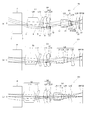
- (A) is a schematic diagram of the image pick-up element based on embodiment of this invention
- (b) is a schematic diagram showing the light beam flux in the arbitrary surfaces orthogonal to the optical axis in an imaging optical system.
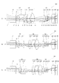
- (A) is a paraxial relation at the wide end of the imaging optical system according to the first embodiment of the present invention
- (b) is a paraxial relation at an intermediate magnification
- (c) is It is a paraxial relationship at the tele end.
- (A) is a paraxial relation at the wide end of the imaging optical system according to the second embodiment of the present invention
- (b) is a paraxial relation at an intermediate magnification
- (c) is It is a paraxial relationship at the tele end.
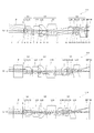
- (A) is a paraxial relation at the wide end of the imaging optical system according to the third embodiment of the present invention, (b) is a paraxial relation at an intermediate magnification, and (c) is It is a paraxial relationship at the tele end.
- (A) is a paraxial relation at the wide end of the imaging optical system according to the fourth embodiment of the present invention, (b) is a paraxial relation at an intermediate magnification, and (c) is It is a paraxial relationship at the tele end.
- (A) is a paraxial relation at the wide end of the imaging optical system according to the fifth embodiment of the present invention, (b) is a paraxial relation at an intermediate magnification, and (c) is It is a paraxial relationship at the tele end.
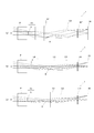
- (A) is a cross-sectional view at the wide end of the imaging optical system according to Example 1 of the present invention, (b) is a cross-sectional view at an intermediate magnification, and (c) is a cross-sectional view at the tele end It is.
- (A) is a cross-sectional view at the wide end of the imaging optical system according to Example 2 of the present invention, (b) is a cross-sectional view at an intermediate magnification, and (c) is a cross-sectional view at the tele end It is.
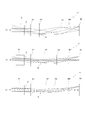
- (A) is a cross-sectional view at the wide end of the imaging optical system according to Example 3 of the present invention
- (b) is a cross-sectional view at an intermediate magnification
- (c) is a cross-sectional view at the tele end It is.
- (A) is a sectional view in the wide end of an imaging optical system concerning Example 4 of the present invention
- (b) is a sectional view in middle magnification
- (c) is a sectional view in a tele end.
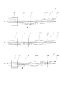
- (A) is sectional drawing in the wide end of the imaging optical system concerning Example 5 of this invention
- (b) is sectional drawing in middle magnification
- (c) is sectional drawing in a tele end. It is.
- (A) is a sectional view in the wide end of the imaging optical system concerning Example 6 of the present invention, (b) is a sectional view in middle magnification, and (c) is a sectional view in a tele end. It is.
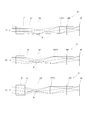
- (A) is a sectional view in the wide end of the imaging optical system concerning Example 7 of the present invention, (b) is a sectional view in middle magnification, and (c) is a sectional view in a tele end. It is.
- (A) is a cross-sectional view at the wide end of the imaging optical system according to Example 8 of the present invention, (b) is a cross-sectional view at an intermediate magnification, (c) is a cross-sectional view at the tele end It is.
- the imaging device 50 has a shape in which the ratio of the length in the vertical direction V (short direction) to the length in the horizontal direction H (long direction) is 3: 4, Called the end.
- V end may refer to the entire end in the V direction or the middle point of the end in the V direction, but will be used in the latter meaning in the following description.
- FIG. 1B shows ray bundles at the four corners of the screen and at the upper and lower V ends.
- the effective area of the optical surface is not axisymmetric.
- the vertical limit of the light flux has the property that it hardly changes between the four corners of the screen and the upper and lower V ends, so the vertical dimension of the lens is It can be considered that it is determined by the height of the ray in the vertical direction of the ray bundle.
- the ratio of the length in the V direction to the length in the H direction of the image pickup device 50 is 9:16 in the case of high definition. That is, V: H is not limited to the ratio of 3: 4 or the ratio of 9:16.
- the subject direction and the V direction of the imaging device 50 are matched, that is, the light flux is bent 90 degrees by a prism or mirror. There is.
- the depth of the optical system in the subject direction is determined by the height of the ray relative to the central axis of the ray bundle corresponding to the V end. Therefore, the present invention is characterized in that the thickness of the imaging optical system in the subject direction is reduced by suppressing the height of the light beam with respect to the central axis of the light bundle at the V end to a low level.
- the imaging optical system will be described in more detail.
- the imaging optical system is an optical system provided with a magnification adjustment function (zooming function).
- This imaging optical system is provided with an optical axis bending means such as a prism or a mirror at the end (front) of the object side.
- the imaging optical system includes a lens group having a function of generating an intermediate image which is a real image behind the optical axis bending means, and an off-axis light beam on the central axis side (central axis direction).
- a lens group having a function of refracting an off-axis light beam in the central axis direction and having a positive power is disposed in the vicinity of a position where an intermediate image is formed. That is, in the imaging optical system according to the present embodiment, an intermediate image is formed before the heights of light beams of light beams emitted from the prism and the mirror become high, and an axis is formed in the vicinity of the position where the intermediate image is formed. By refracting the external light flux in the central axis direction, the height of the light beam in the entire optical system is kept low.
- the chief ray which is a ray passing through the center of the stop, and the central axis (optical axis) intersect at two places before and after the intermediate image. Therefore, the stop is disposed at one of two positions before and after the intermediate image.
- the imaging optical system in this embodiment having such a configuration, it is possible to suppress the height of the ray at the V end to a low level.
- the optical system can not be made thinner (the thickness in the subject direction can be reduced).
- the thickness of the optical system is determined by the screen size in the V direction in that case, it is not necessary to further lower the height of the ray at the V end in the optical system. That is, if the ray height at the V end can be kept low, the lens can be cut so as not to cut the ray bundle at the V end, and it is possible to make the entire optical system thin.
- a thick concave lens is disposed in front of the optical axis bending means, or negative power is given to the front surface of the prism as the optical axis bending means.
- thinning of the imaging optical system can be realized. That is, according to the present embodiment, thinning and downsizing of the imaging optical system can be realized without using a thick concave lens or an optical axis bending means (prism) with an increased thickness. It is possible to provide an imaging optical system that can be easily incorporated into an electronic device.
- the imaging optical system in the present embodiment forms an intermediate image before the height of the light beam becomes high, and refracts the off-axis light beam in the central axis direction. Can be kept low. Then, by keeping the light height at the V end low, it is possible to realize a thin imaging optical system.
- each lens group does not have to be composed of a plurality of lenses, and each group may be composed of one lens as long as the above functions can be realized.
- each lens group that realizes the above three functions does not have to be an independent lens group as a moving group for magnification adjustment (zooming), and the function of generating an intermediate image and refraction of an off-axis ray bundle in the axial direction
- a plurality of functions may be provided to one lens group, such as a moving group having a function to perform.
- a lens group fixed to the front (subject side) or the rear (image sensor side) of the lens group may be disposed.
- an optical component with a small thickness such as a filter or protective glass, may be disposed in front of the optical axis bending means.
- the subject side is referred to as the front
- the imaging device side is described as the rear.
- FIG. 2 is a diagram showing a paraxial relationship of the imaging optical system 1 according to the first embodiment of the present invention.
- 2A shows the wide-angle end (wide end)
- FIG. 2B shows the intermediate magnification
- FIG. 2C shows the telephoto end.
- a ray bundle projected on the center (center of the screen) of the imaging device 50 and a ray bundle at one V end are displayed as paraxial rays.
- the imaging optical system 1 is provided with a prism P as an optical axis bending means at the front end, and is movable at the rear of the prism P with a stop S and positive power.
- a first group G1 including a lens group is provided.
- the imaging optical system 1 includes a second lens group G2 which is a movable lens group having positive power behind the first lens group G1, and a movable lens which has positive power behind the second lens group G2.
- a third group G3 which is a group is provided.
- the imaging optical system 1 further includes an infrared filter IRF behind the third group G3, and an imaging element 50 such as a CCD or CMOS behind the infrared filter IRF.
- FIGS. 3 to 6 the lens units of the respective groups G1, G2 and G3 are schematically shown by one thin lens, and the same applies to FIGS. 3 to 6 in other embodiments.
- These schematic diagrams are for showing that the power of each group is positive, the rough position of the intermediate image, whether each group is fixed movable, and the interlocking relationship of each group, and the power of each group is It is not limited to the value or the position of each group.
- the prism P is an optical axis bending means that bends a light flux incident from the entrance surface by 90 degrees and emits the light flux from the exit surface.
- the prism P is described as a flat lens in order to make it easy to understand the progress of the ray bundle, but in reality it is a prism capable of bending the ray bundle.
- the optical axis bending means is not limited to the prism but may use a mirror or the like.
- the optical axis bending means is not limited to the prism, and may use a mirror or the like, as in the second to fifth embodiments described below.
- the stop S is disposed on the side close to the prism P, and the distance between the stop S and the movable lens group having positive power is fixed.
- the first group G1 has a function of generating an intermediate image II, and an intermediate image II is generated behind the first group G1.
- the second group G2 is disposed in the vicinity of the intermediate image II generated by the first group G1, and has a function of refracting the off-axis light flux in the direction of the central axis O.
- the second group G2 has a function of relaying the intermediate image II generated in the first group G1.
- the second group G2 has a part of the function of relaying the intermediate image II.
- the third group G3 is disposed closest to the imaging element 50 (in the first group G1, the second group G2, and the third group G3), and the light flux refracted in the second group G2 is transmitted to the imaging element 50. It has a function of imaging.
- zooming is performed by moving the three lens groups of the first group G1, the second group G2, and the third group G3 along the axis, and the first group G1 is along the axis.
- the entire focal length is negative because there is one intermediate image II. Since the second group G2 is placed near the intermediate image, the imaging magnification by the second group G2 is about 1. Since the ratio of the size of the intermediate image II to the size of the final image formation is about -1 at the wide end, the imaging magnification by the third group G3 is about -1 at the wide end.
- the focal length of the first group G1 is the total focal point at the wide end because the overall focal length is the product of the focal length of the first group G1 and the imaging magnification by the second group G2 and the imaging magnification by the third group G3. It has the same size as the distance (inverse sign).
- the focal length of the second group G2 functions to determine the entrance pupil position for the third group G3, and the exit pupil position of the entire optical system is determined from the entrance pupil position for the third group G3.
- the exit pupil position of the entire optical system influences the direction of incidence of the chief ray on the imaging device 50. Then, there is a condition for each imaging device 50 in the incident direction of the chief ray to the imaging device 50. In that sense, the range of the focal length of the second group G2 may be wide. Further, in an optical system using many aspheric surfaces, the incident direction of the chief ray to the image sensor 50 at the periphery of the screen is not uniquely determined from only the paraxial exit pupil position. Also from this aspect, the range of the focal length of the second group G2 may be wide.
- the focal length of the third group G3 has a function of determining the distance from the intermediate image II to the final imaging. That is, the longer the focal length of the third group G3 is, the longer the overall length of the optical system, and the shorter the focal length of the third group G3, the shorter the overall length of the optical system.
- the total length of the entire optical system should be short, but as the focal length of the third lens group G3 decreases, the amount of aberration generated increases. Therefore, the appropriate focal length of the third lens group G3 depends on the size and performance of the optical system. Determined from the balance of requirements. Further, since the second group G2 has a part of the function of relaying the intermediate image II, the focal length of the third group G3 is affected by the action of the second group G2.
- the power arrangement of each group is conditioned as follows.
- the numerical values in Table 1 are numerical values calculated by the focal length (FGi) of each group / the total focal length (F) at the wide end.
- means an absolute value.
- the first group G1 preferably has a minimum of 0.5 and a maximum of 3.0.
- the second group G2 is preferably at least 0.5 and at most INFINITY (infinite), that is, 0.5 or more.
- the third group G3 is preferably at least 0.5 and at most 1.5. In addition, it is not necessarily limited to the numerical value of this Table 1.
- an intermediate image is generated by the first group G1 and the off-axis light flux is refracted inward by the second group G2, so that the height of light at the V end can be suppressed low. That is, according to the present embodiment, since the height of the light beam at the V end can be suppressed low, it is possible to provide a thin imaging optical system 1 with a thin thickness in the subject direction.
- the three lens groups are moved independently for zooming, so that the degree of freedom in design is high.
- the stop S is disposed in the first group G1, but the present invention is not limited to this position.
- the stop S in order to generate the intermediate image II, there are two places where the diaphragm S can be disposed. Therefore, the stop S can be disposed in the rear surface of the first group G1 or the prism P which is in front of the intermediate image II or in the third group G3 which is in the rear of the intermediate image II.
- the difference between the main effects of the optical system in the case where the stop is arranged in front of the intermediate image II and in the case where the stop is arranged behind the intermediate image II is the FNO when zooming with the fixed stop diameter. This is the difference in the amount of fluctuation of (brightness of the optical system).
- FNO gradually increases (that is, the optical system becomes darker) from the wide end to the tele end.
- the amount of fluctuation of FNO is generally smaller in the case where the stop is disposed behind the intermediate image II than in the case where the stop is disposed in front of the intermediate image II.
- the amount of FNO variation desired is a matter depending on the purpose and application of each optical system, and according to it, it will be selected where to place the aperture.
- FIG. 3 shows a paraxial relationship of the imaging optical system 11 in the second embodiment of the present invention.
- 3A shows the wide angle end (wide end)
- FIG. 3B shows the intermediate magnification
- FIG. 3C shows the telephoto end. It is to be noted that the same reference numerals are given to the same elements as those in the first embodiment, and the redundant description will be omitted.
- the three lens groups are moved independently for zooming, but in the present embodiment, one of the three lens groups is fixed without being used for zooming.
- the magnification change mechanism is simplified. That is, the imaging optical system 11 of the present embodiment is characterized in that the first group G1 is moved only for focusing without using zooming.
- the imaging optical system 11 of the present embodiment will be described in detail.
- the imaging optical system 11 in the present embodiment is provided with a prism P as an optical axis bending means at the front end, and a diaphragm S is formed on the rear surface of this prism P.
- the imaging optical system 11 includes a first group G1 which is a movable lens group having positive power behind the prism P, and a movable lens group having positive power behind the first group G1.
- a second lens group G2 and a third lens group G3 which is a movable lens group having positive power are sequentially provided.
- the imaging optical system 11 further includes an infrared filter IRF and an imaging device 50 behind the third group G3.
- the first group G1 has a function of generating the intermediate image II as in the first embodiment, and the intermediate image II is generated behind the first group G1.
- the second group G2 is disposed in the vicinity of the intermediate image II generated by the first group G1 and has a function of refracting an off-axis light beam in the axial direction. ing.
- the second group G2 has a function of relaying the intermediate image II generated in the first group G1.
- the second group G2 has a part of the function of relaying the intermediate image II.
- the third group G3 is also disposed closest to the imaging element 50 (in the first group G1, the second group G2, and the third group G3), and is refracted by the second group G2
- the light flux has a function of forming an image on the image sensor 50.
- zooming is performed by moving the second lens group G2 and the third lens group G3 along the axis to perform zooming, and moving the first group G1 along the axis.
- the imaging optical system 11 of the present embodiment has a magnification adjustment function and a focus adjustment function, and the first group G1 moves along the axis only at the time of focusing.
- the first group G1 has a minimum of 0.5 and a maximum of 3.0.
- the second group G2 is preferably at least 0.5 and at most INFINITY.
- the third group G3 is preferably at least 0.5 and at most 1.5. In addition, it is not necessarily limited to the numerical value of this Table 2.
- an intermediate image is generated in the first group G1 and an off-axis light flux is refracted in the second group G2, so that the height of the light flux at the V end can be kept low.
- the imaging optical system 11 of the present embodiment has an advantage that the control of focusing can be simplified since the focusing is separated from the zooming.
- the diaphragm S is disposed on the rear surface of the prism P, but the present invention is not limited to this position.
- the stop S can be disposed in the rear surface of the first group G1 or the prism P which is in front of the intermediate image II or in the third group G3 which is in the rear of the intermediate image II.
- FIG. 4 is a diagram showing a paraxial relationship of the imaging optical system 21 in the third embodiment of the present invention.
- FIG. 4A shows the wide angle end (wide end)
- FIG. 4B shows the intermediate magnification
- FIG. 4C shows the telephoto end (tele end).
- the imaging optical system 21 in the present embodiment is characterized in that two lens groups out of three lens groups are connected and moved integrally. That is, the present embodiment is characterized in that the first group G1 and the second group G2 are connected.
- the imaging optical system 21 of the present embodiment will be described in detail.
- the imaging optical system 21 in the present embodiment is provided with a prism P as an optical axis bending means at the front end.
- the imaging optical system 21 has a first group G1 and a second group G2 which are movable lens groups having positive power behind the prism P, and has positive power behind the second group G2.
- the third lens group G3 is provided as a movable lens group.
- the first group G1 and the second group G2 have a fixed interval to constitute a front group GF, and the third group G3 constitutes a rear group GR.
- the imaging optical system 21 further includes an infrared filter IRF and an imaging element 50 behind the third group G3 (rear group GR).
- the first group G1 has a function of generating the intermediate image II as in the first and second embodiments, and the intermediate image II is generated behind the first group G1.
- the second group G2 is also disposed in the vicinity of the intermediate image II generated by the first group G1, and refracts the off-axis light flux inward (axially). It has a function.
- the second group G2 also has a function of relaying the intermediate image II generated in the first group, as in the other embodiments. In other words, the second group G2 has a part of the function of relaying the intermediate image II.
- the third group G3 (rear group GR) is also disposed closest to the imaging element 50 (in the first group G1, the second group G2, the third group G3) as in the other embodiments described above, and It has a function of forming an image of the light flux refracted by the second group G2 on the imaging device 50. Further, in the present embodiment, the stop S is disposed in the third group G3.
- the imaging optical system 21 in the present embodiment includes a front group GF configured by the first group G1 and the second group G2, and a rear group GR configured by the third group G3.
- the front group GF has a function of forming an intermediate image, a function of refracting an off-axis light beam inward, and a part of relaying the intermediate image II.
- the front group GF is described as being composed of the first group G1 and the second group G2, in an actual optical system, it is not necessary to clearly separate the first group G1 and the second group G2.
- zooming is performed by moving the front group GF configured by the first group G1 and the second group G2 and the rear group GR that is the third group G3 along an axis.
- Focusing is performed by moving the entire front group GF along an axis. That is, the imaging optical system 21 of the present embodiment has a magnification adjustment function and a focus adjustment function.
- the power distribution of each group in the imaging optical system 21 (focal length of each group (FGi) /
- the front group GF preferably has a minimum of 0.5 and a maximum of 3.0.
- the rear group GR is preferably at least 0.5 and at most 1.5. In addition, it is not necessarily limited to the numerical value of this Table 3.
- the imaging optical system 21 since the intermediate image is generated by the front group GF and the off-axis light flux is refracted inward, the light height of the light flux at the V end can be suppressed to a low level.
- a thin imaging optical system 21 can be provided. Further, since the imaging optical system 21 of the present embodiment is constituted by the front group GF and the rear group GR, there are advantages that the mechanism can be simplified since there are two moving groups.
- the stop S is disposed in the third group G3, but the present invention is not limited to this position.
- the stop S in order to generate the intermediate image II, there are two places where the diaphragm S can be disposed. Therefore, the stop S can be disposed in the rear surface of the first group G1 or the prism P which is in front of the intermediate image II or in the third group G3 which is in the rear of the intermediate image II.
- FIG. 5 is a diagram showing a paraxial relationship of the imaging optical system 31 in the fourth embodiment of the present invention.
- 5A shows the wide angle end (wide end)
- FIG. 5B shows the intermediate magnification
- FIG. 5C shows the telephoto end (tele end).
- the present embodiment is characterized in that the zooming mechanism is simplified by performing zooming while fixing the second group G2.
- the imaging optical system 31 of the present embodiment will be described in detail.
- the imaging optical system 31 in the present embodiment is provided with a prism P as an optical axis bending means at the front end. Further, the imaging optical system 31 is a fixed lens group provided with a first group G1 which is a movable lens group having positive power behind the prism P and having positive power behind the first group G1. A second lens group G2 is provided, and a third lens group G3 which is a movable lens group having a positive power is provided at the rear of the second lens group G2. The imaging optical system 31 further includes an infrared filter IRF and an imaging element 50 at the rear of the third group G3.
- the first group G1 has a function of generating the intermediate image II as in the other embodiments described above, and the intermediate image II is generated behind the first group G1.
- the second group G2 in the present embodiment is fixed.
- the second group G2 is disposed in the vicinity of the intermediate image II generated by the first group G1 as in the other embodiments described above, and has a function of refracting an off-axis light beam in the axial direction. Have.
- the second group G2 has a function of relaying the intermediate image II generated in the first group G1.
- the second group G2 has a part of the function of relaying the intermediate image II.
- the third group G3 is also disposed closest to the imaging element 50 (in the first group G1, the second group G2, and the third group G3) as in the other embodiments described above, and is refracted by the second group G2
- the light flux has a function of forming an image on the image sensor 50.
- the stop S is disposed in the third group G3.
- the imaging optical system 31 of the present embodiment has a magnification adjustment function and a focus adjustment function.
- the first group G1 preferably has a minimum of 0.5 and a maximum of 3.0.
- the second group G2 is preferably at least 0.5 and at most INFINITY.
- the third group G3 is preferably at least 0.5 and at most 1.5. In addition, it is not necessarily limited to the numerical value of this Table 4.
- the imaging optical system 31 in this embodiment the intermediate image II is generated in the first group G1 and the off-axis luminous flux is refracted in the second group G2, so that the ray height of the ray bundle at the V end is kept low.
- the imaging optical system 31 of the present embodiment has an advantage that the mechanism can be simplified since the moving group is two, and there is an advantage that the weight of the moving group is small because the second group G2 is fixed.
- the stop S is disposed in the third group G3, but the present invention is not limited to this position.
- the stop S in order to generate the intermediate image II, there are two places where the diaphragm S can be disposed. Therefore, the stop S can be disposed in the rear surface of the first group G1 or the prism P which is in front of the intermediate image II or in the third group G3 which is in the rear of the intermediate image II.
- FIG. 6 is a diagram showing the paraxial relationship of the imaging optical system 41 in the fifth embodiment of the present invention.
- 6A shows the wide-angle end (wide end)
- FIG. 6B shows the middle magnification
- FIG. 6C shows the telephoto end (tele end).
- the imaging optical system 41 according to the present embodiment is characterized in that the zooming mechanism is simplified by connecting the first group G1 and the third group G3 to perform zooming.
- the imaging optical system 41 of the present embodiment is characterized in that the second group G2 is fixed.
- the imaging optical system 41 in the present embodiment is provided with a prism P as an optical axis bending means at the front end.
- the imaging optical system 41 is a fixed lens group including a first group G1 which is a movable lens group having positive power behind the prism P and having positive power behind the first group G1.
- a second lens group G2 is provided, and a third lens group G3 which is a movable lens group having a positive power is provided at the rear of the second lens group G2.
- the imaging optical system 41 further includes an infrared filter IRF and an imaging device 50 behind the third group G3.
- a stop S is disposed on the rear surface of the prism P.
- the first group G1 has a function of generating the intermediate image II as in the other embodiments described above, and the intermediate image II is generated behind the first group G1.
- the second group G2 in the present embodiment is fixed.
- the second group G2 is disposed in the vicinity of the intermediate image II generated by the first group G1 as in the other embodiments described above, and has a function of refracting an off-axis light beam in the axial direction. Have.
- the second group G2 has a function of relaying the intermediate image II generated in the first group. In other words, the second group G2 has a part of the function of relaying the intermediate image II.
- the third group G3 is also disposed closest to the imaging element 50 (in the first group G1, the second group G2, and the third group G3) as in the above embodiments, and is refracted by the second group G2 It has a function of forming an image of a light beam on the imaging device 50.
- the second group G2 is fixed, and the zooming is performed by connecting the first group G1 and the third group G3.
- EDoF Extended Depth of Field
- EDoF is an image processing technology that widens the depth of field. Also, since the EDoF function is used, a moving group for focusing is not necessary.
- the power distribution of each group in the imaging optical system 41 (focal length of each group (FGi) /
- the first group G1 has a minimum of 0.5 and a maximum of 3.0.
- the second group G2 is preferably at least 0.5 and at most INFINITY.
- the third group G3 is preferably at least 0.5 and at most 1.5. In addition, it is not necessarily limited to the numerical value of this Table 5.
- the first group G1 generates the intermediate image II
- the second group G2 refracts the off-axis light flux inward, so a thin imaging optical system 41 having a thin thickness in the subject direction is obtained.
- the second group G2 since the second group G2 is fixed and the first group G1 and the third group G3 are connected and moved, the control of the movable part becomes easy.
- the diaphragm S is disposed on the rear surface of the prism P, but the present invention is not limited to this position.
- the stop S can be disposed in the rear surface of the first group G1 or the prism P which is in front of the intermediate image II or in the third group G3 which is in the rear of the intermediate image II.
- One method of simplifying the magnification changing mechanism is to fix one group, and in the second embodiment, fix the first group G1 and fix the second group G2 in the fourth embodiment. doing.
- Another method of simplifying the magnification changing mechanism is to connect two groups, and in the third embodiment, the first group G1 and the second group G2 are connected, and in the fifth embodiment The first group G1 and the third group G3 are connected.
- the case of fixing the third group G3 and the case of connecting the second group G2 and the third group G3 can be considered.
- fixing the third group G3 is unsuitable because the third group G3 functions as a variator, and connecting the second group G2 and the third group G3 is a ray at the V end. It is unsuitable because it makes it difficult to keep the bundle height low.
- the second group G2 is moved for zooming and does not use the EDoF function in relation to the fifth embodiment, but it is the fact that such an embodiment holds true. This is clear from the fifth embodiment.
- the lens configurations in the following embodiments are examples showing that the first to fifth embodiments are effective for realizing a thin imaging optical system in which the thickness in the subject direction is thin.
- the present invention is not limited to the following examples because there are many lens configurations other than the examples.
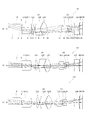
- FIG. 7 is a cross-sectional view of the imaging optical system 101.
- the effective diameter of each lens in this cross-sectional view corresponds to the light flux at the maximum image height.
- a ray bundle projected on the center (center of the screen) of the imaging device 50 and a ray bundle at one V end are displayed.
- the imaging optical system 101 is an example of the imaging optical system 1 described in the first embodiment.
- the imaging optical system 101 of this embodiment includes a first group G1, a second group G2 and a third group G3 which are movable lens groups having positive power in order behind the prism P.
- the fixed lens L41 is disposed, and on the rear surface of the fixed lens L41, the infrared filter IRF and the imaging device 50 are disposed in order.
- a stop S is formed on the rear surface of the prism P.
- the first group G1 is composed of a cemented lens of a first lens L11 which is a biconvex lens, and a second lens L12 which is a meniscus lens whose front surface is concave and whose rear surface is convex.
- the second group G2 has a third lens L21 having a concave front surface and a convex rear surface, a fourth lens L22 having a convex front surface and a concave rear surface, and a fifth lens L23 having a double convex lens. And consists of
- the third group G3 includes a sixth lens L31 having a concave front surface and a convex rear surface meniscus lens, a seventh lens L32 having a convex front surface and a concave rear surface meniscus lens, and a convex rear surface and a rear surface concave And an eighth lens L33 which is a meniscus lens.
- the fixed lens L41 is a meniscus lens having a convex front surface and a concave rear surface. All the lenses in the first to third groups G1 to G3 and the fixed lens L41 are aspheric lenses except for the cemented surface 4.
- the imaging optical system 101 of this embodiment moves the first group G1, the second group G2, and the third group G3 to perform zooming, and moves the first group G1 to perform focusing.
- Table 6 below shows the specifications of the imaging optical system 101 shown in FIG.
- ⁇ shown in the entire specification represents a half angle of view at the wide end
- FNO is a numerical value obtained by dividing the focal length by the entrance pupil diameter (focal length / incident pupil diameter) and represents the brightness of the optical system.
- the aperture diameter is fixed during zooming, so that FNO fluctuates with zooming.
- FNO in the table is the value at the wide end.
- F represents the focal length at the wide end of the entire lens
- Y represents the maximum image height.
- the overall focal length F at the wide end is ⁇ (negative) in order to form an intermediate image.
- L represents the total length of the imaging optical system 101 (the distance from the front surface of the prism to the image plane in the state where the prism P is developed on the reflection surface).
- m indicates the number (surface number) of each optical surface from the subject side (front end) (corresponding to the number in FIG. 7A)
- r indicates the radius of curvature of each optical surface
- d Represents the distance (surface distance) on the optical axis from each optical surface to the next optical surface.
- indicates the focal length of each group (FGi) /
- the definition of the aspheric coefficient is expressed by equation (1).
- z displacement amount in the z-axis direction at the position of height h (surface vertex reference)
- A, B, C, D, E, F Aspheric coefficients
- K Conic coefficients of the fourth, sixth, eighth, tenth, twelfth, and fourteenth orders, respectively.
- W in the group interval represents the wide end
- M represents the intermediate magnification
- T represents the tele end.
- the numerical values of the focal length (FGi) of each group in the present embodiment and the total focal length (F) at the wide end satisfy the conditions shown in Table 1.
- the maximum luminous flux width of the V end luminous flux is 3.4 mm
- substantially the same numerical value as the numerical value 3.414 mm of the screen size in the V direction is realized. Therefore, it is possible to realize a thin imaging optical system in which the thickness in the subject direction is thin.
- the total lens length L is as short as 26.92 mm, it is possible to provide a compact imaging optical system that can be easily incorporated into a compact electronic device having a limited arrangement space of the imaging optical system.
- FIG. 8 is a cross-sectional view of the imaging optical system 111 of the present embodiment.
- the imaging optical system 111 is an example of the imaging optical system 11 described in the second embodiment.
- the imaging optical system 111 of the present embodiment is provided with a first group G1 which is a lens group having positive power behind a prism P, and movable with positive power behind the first group G1.
- the second lens group G2 and the third lens group G3 which are lens groups are provided.
- an infrared filter IRF and an imaging device 50 are disposed in order in the rear of the third group G3.
- the stop S is disposed behind the prism P and at the front end (subject side) of the first group G1.
- the first group G1 is composed of a cemented lens of a first lens L11 which is a biconvex lens, and a second lens L12 which is a meniscus lens whose front surface is concave and whose rear surface is convex.
- the second lens group G2 includes a third lens L21 which is a biconvex lens, a fourth lens L22 which is a meniscus lens having a concave front surface and a convex rear surface, and a fifth lens L23 which is a meniscus lens having a concave front surface and a convex rear surface And consists of
- the third group G3 includes a sixth lens L31 which is a biconvex lens, and a seventh lens L32 which is a meniscus lens whose front surface is convex and whose rear surface is concave. Further, the third lens group G3 is an eighth lens L33 having a concave front surface and a convex rear surface posterior to the seventh lens L32, and a ninth lens L34 having a convex front surface and a concave rear surface. And. All the lenses in the first group G1 to the third group G3 are aspheric lenses except for the cemented surface 5.
- the imaging optical system 111 of this embodiment zooms in the second group G2 and the third group G3 and performs focusing in the first group G1.
- Table 7 below shows the specifications of the imaging optical system 111 shown in FIG.
- the numerical values of the focal length (FGi) of each group in the present embodiment and the total focal length (F) at the wide end satisfy the conditions shown in Table 2.
- the maximum luminous flux width of the V end luminous flux is 3.6 mm and is a numerical value close to 3.414 mm which is the numerical value in the V direction of the screen size, a thin imaging optical system with thin thickness in the subject direction is realized ing.
- the total lens length L is as short as 29.51 mm, it is possible to provide a compact imaging optical system that can be easily incorporated into a compact electronic device having a limited arrangement space of the imaging optical system.
- FIG. 9 is a cross-sectional view of the imaging optical system 121 of the present embodiment.
- the imaging optical system 121 is an example of the imaging optical system 21 described in the third embodiment.
- the imaging optical system 121 of the present embodiment includes a front group GF (first group G1 and second group G2), which is a movable lens group having positive power behind the prism P, It has a rear group GR (third group G3) which is a movable lens group having positive power behind GF. Further, behind the rear group GR, an infrared filter IRF and an imaging device 50 are disposed in order.
- the stop S is disposed between an eighth lens L32 and a ninth lens L33 in the rear group GR, which will be described later.
- the front group GF (first group G1 and second group G2) includes a first lens L11 which is a biconvex lens, a second lens L12 which is a biconvex lens, and a third lens which is a meniscus lens having a concave front surface and a convex rear surface.
- a lens L21 is provided as a first group G1.
- the front lens group GF includes a fourth lens L22 having a concave front surface and a convex rear surface meniscus lens, a fifth lens L23 having a convex front surface and a concave rear surface meniscus lens, and a sixth convex lens having a double convex lens.
- L24 as a second group G2.
- the first group G1 and the second group G2 are used, the first group G1 and the second group G2 do not necessarily have to be divided into such groups, and an intermediate image is generated in the entire front group GF and an off-axis light beam is It only needs to have the function of refracting in the direction.
- the rear group GR is disposed behind the eighth lens L32 via the stop S with the seventh lens L31 being a meniscus lens having a concave front surface and a convex rear surface, and a biconvex lens eighth lens L32. It is comprised from the 9th lens L33 which is a concave lens, and the 10th lens L34 which is a biconvex lens. All the lenses in the front group GF and the rear group GR (the first group G1 to the third group G3) are aspheric lenses.
- the imaging optical system 121 of this embodiment performs zooming with the front group GF and the rear group GR, and performs focusing with the front group GR.
- Table 8 below shows the specifications of the imaging optical system 121 shown in FIG.
- the numerical values of the focal length (FGI) of the groups in the present example and the total focal length (F) at the wide end satisfy the conditions shown in Table 3.
- the maximum luminous flux width of the V end luminous flux is 4.0 mm and is a numerical value close to 3.414 mm which is the numerical value in the V direction of the screen size, a thin imaging optical system with thin thickness in the subject direction is realized ing.
- the total lens length L is as short as 30.00 mm, it is possible to provide a compact imaging optical system that can be easily incorporated in a compact electronic device having a limited arrangement space of the imaging optical system.
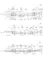
- FIG. 10 is a cross-sectional view of the imaging optical system 131 of the present embodiment.
- the imaging optical system 131 is an example of the imaging optical system 11 described in the second embodiment.
- the imaging optical system 131 of the present embodiment is provided with a first lens L11 (first group G1) which is a movable lens having positive power behind a prism P, and behind the first lens L11.
- the second lens group G2 and the third lens group G3, which are movable lens groups having positive power, are provided.
- a fixed lens L41 is disposed behind the third group G3, and an infrared filter IRF and an imaging device 50 are sequentially disposed behind the fixed lens L41.
- the stop S is formed on the rear surface of the prism P.
- the first lens L11 (first group G1) is a biconvex lens.
- the second group G2 includes a second lens L21 having a concave front surface and a convex rear surface, a third lens L22 having a convex front surface and a concave rear surface, and a fourth lens L23 having a biconvex lens. And consists of
- the third group G3 is composed of a fifth lens L31 which is a biconvex lens, a sixth lens L32 which is a meniscus lens having a convex front surface and a concave rear surface, and a seventh lens L33 which is a biconcave lens .
- the fixed lens L41 is a meniscus lens having a convex front surface and a concave rear surface. All the lenses in the first to third groups G1 to G3 and the fixed lens L41 are aspheric lenses.
- the imaging optical system 131 of the present embodiment performs zooming in the second group G2 and the third group G3 and performs focusing in the first group G1.
- Table 9 below shows the specifications of the imaging optical system 131 shown in FIG.
- the numerical values of the focal length (FGi) of each group in the present embodiment and the total focal length (F) at the wide end satisfy the conditions shown in Table 2.
- the maximum luminous flux width of the V end luminous flux is 3.4 mm
- substantially the same numerical value as the numerical value 3.414 mm of the screen size in the V direction is realized. Therefore, a thin imaging optical system with a thin thickness in the subject direction is realized.
- the total lens length L is as short as 30.00 mm, it is possible to provide a compact imaging optical system that can be easily incorporated in a compact electronic device having a limited arrangement space of the imaging optical system.
- the medium of L22, L31, L33 and L41 is plastic, and the cost can be reduced as compared with the glass molded lens.
- FIG. 11 is a cross-sectional view of the imaging optical system 141 of the present embodiment.
- the imaging optical system 141 is an example of the imaging optical system 1 described in the first embodiment.
- the imaging optical system 141 of this embodiment includes a first lens group G1, a second lens group G2 and a third lens group G3 which are movable lens groups having positive power in order behind the prism P.
- an infrared filter IRF and an imaging device 50 are disposed in order in the rear of the third group G3.
- the aperture stop S is disposed at the front end (subject side) of the first group G1.
- the first group G1 has a stop S, a first lens L11 which is a meniscus lens having a convex front surface located rearward of the stop S, and a concave rear surface, a second lens L12 which is a biconvex lens, and a front surface which is concave And a third lens L13 which is a convex meniscus lens.
- the second lens group G2 includes a fourth lens L21 having a concave front surface and a convex rear surface meniscus lens, a fifth lens L22 having a concave front surface and a convex rear surface meniscus lens, and a concave rear surface and a rear surface convex And a sixth lens L23 which is a meniscus lens.
- the third group G3 has a seventh lens L31 which is a biconvex lens, an eighth lens L32 which is a meniscus lens whose front surface is convex and a concave rear surface, and a ninth lens L33 which is a biconcave lens, whose front surface is convex, And a tenth lens L34 which is a meniscus lens having a concave rear surface. All the lenses in the first group G1 to the third group G3 are aspheric lenses.
- the imaging optical system 141 of the present embodiment moves the first group G1, the second group G2, and the third group G3 to perform zooming, and moves the first group G1 to perform focusing.
- Table 10 below shows the specifications of the imaging optical system 141 shown in FIG.
- the numerical values of the focal length (FGi) of each group in the present embodiment and the total focal length (F) at the wide end satisfy the conditions shown in Table 1.
- the maximum luminous flux width of the V end luminous flux is 3.6 mm
- substantially the same numerical value as 3.414 mm, which is the numerical value in the V direction of the screen size, is realized. Therefore, a thin imaging optical system with a thin thickness in the subject direction is realized.
- the total lens length L is as short as 29.83 mm, it is possible to provide a compact imaging optical system that can be easily incorporated into a compact electronic device having a limited arrangement space of the imaging optical system.
- the medium of L13, L22, L23 and L34 is plastic, and the cost can be reduced as compared with the glass molded lens.
- FIG. 12 is a cross-sectional view of the imaging optical system 151 of the present embodiment.
- the imaging optical system 151 is an example of the imaging optical system 31 described in the fourth embodiment.
- the imaging optical system 151 of this embodiment includes a first group G1 which is a movable lens group having a positive power behind a prism P, and has a positive power behind the first group G1.
- a third lens group G3 which is a movable lens group having a positive power behind the second lens group G2.
- an infrared filter IRF and an imaging device 50 are disposed in order in the rear of the third group G3.
- the stop S is disposed between a seventh lens L32 and an eighth lens L33 in a third group G3 described later.
- the first group G1 is composed of a first lens L11 which is a biconvex lens, and a second lens L12 which is a meniscus lens whose front surface is convex and whose rear surface is concave.
- the second group G2 includes a third lens L21 which is a biconvex lens, a fourth lens L22 which is a biconcave lens, and a fifth lens L23 which is a biconvex lens.
- the third group G3 includes a sixth lens L31 which is a biconvex lens, and a seventh lens L32 which is a meniscus lens whose front surface is convex and whose rear surface is concave. Furthermore, the third group G3 is disposed at the rear of the seventh lens L32 via the stop S, and is an eighth lens L33 which is a meniscus lens having a convex front surface and a concave rear surface, and a convex front surface and a concave rear surface. And a ninth lens L34 which is a meniscus lens. All the lenses in the first group G1 to the third group G3 are aspheric lenses.
- the imaging optical system 151 of the present embodiment moves the first group G1 to perform focusing while moving the first group G1 and the third group G3 with the second group G2 being fixed and performing zooming.
- Table 11 below shows the specifications of the imaging optical system 151 shown in FIG.
- FIG. 13 is a cross-sectional view of the imaging optical system 161 of the present embodiment.
- the imaging optical system 161 is an example of the imaging optical system 41 described in the fifth embodiment.
- the imaging optical system 161 of this embodiment includes a first group G1 which is a movable lens group having a positive power behind a prism P, and has a positive power behind the first group G1.
- a third lens group G3 which is a movable lens group having a positive power behind the second lens group G2.
- an infrared filter IRF and an imaging device 50 are disposed in order in the rear of the third group G3.
- the stop S is disposed on the rear surface of the prism P.
- the first group G1 includes a first lens L11 which is a biconvex lens, a second lens L12 which is a meniscus lens whose front surface is convex and a concave rear surface, and a third lens L13 which is a meniscus lens whose front surface is convex and whose rear surface is concave And consists of
- the second group G2 is composed of a fourth lens L21 which is a biconvex lens, a fifth lens L22 which is a meniscus lens having a convex front surface and a concave rear surface, and a sixth lens L23 which is a biconvex lens.
- the third group G3 is composed of a seventh lens L31 which is a biconcave lens, an eighth lens L32 which is a biconvex lens, and a ninth lens L33 which is a biconvex lens. All the lenses in the first group G1 to the third group G3 are aspheric lenses.
- the imaging optical system 161 performs zooming by fixing the second group G2 and moving the first group G1 and the third group G3 in a linked manner. Focusing is not done mechanically but with the EDoF function.
- Table 12 below shows the specifications of the imaging optical system 161 shown in FIG.
- the numerical values of the focal length (FGI) of each group in the present example and the total focal length (F) at the wide end satisfy the conditions shown in Table 5. Further, since the maximum luminous flux width of the V end luminous flux is 4.0 mm, a numerical value close to 3.414 mm, which is the numerical value in the V direction of the screen size, is realized. Therefore, a thin imaging optical system with a thin thickness in the subject direction is realized. Furthermore, since the total lens length L is as short as 30.00 mm, it is possible to provide a compact imaging optical system that can be easily incorporated in a compact electronic device having a limited arrangement space of the imaging optical system.
- FIG. 14 is a cross-sectional view of the imaging optical system 171 of the present embodiment.
- the effective diameter of each lens in this cross-sectional view corresponds to the luminous flux at the V end.
- a ray bundle projected on the center (center of the screen) of the imaging device 50 and a ray bundle at the upper and lower V ends are displayed.
- the imaging optical system 171 is an example of the imaging optical system 1 described in the first embodiment.
- the imaging optical system 171 of the present embodiment includes a mirror REF as an optical axis bending means.
- a protective glass PL is provided immediately before the mirror REF, and a first lens group G1, a second lens group G2, and a third lens group G3 which are movable lens groups having positive power in order behind the mirror REF are provided.
- an infrared filter IRF and an imaging device 50 are disposed in order in the rear of the third group G3.
- the aperture stop S is disposed at the front end (subject side) of the first group G1.
- the first group G1 is composed of a first lens L11 which is a biconvex lens, and a cemented lens of a second lens L12 and a third lens L13.
- the second lens L12 is a meniscus lens having a concave front surface and a convex rear surface
- the third lens L13 is a meniscus lens having a concave front surface and a convex rear surface.
- the second lens group G2 includes a fourth lens L21 which is a biconvex lens, a fifth lens L22 which is a meniscus lens having a convex front surface and a concave rear surface, and a sixth lens L23 which is a meniscus lens having a concave front surface and a convex rear surface. And consists of
- the third group G3 is a biconcave lens disposed on the rear of the eighth lens L32 via the stop S with the seventh lens L31 which is a biconvex lens, the eighth lens L32 which is a biconvex lens, and the ninth It comprises a lens L33 and a tenth lens L34 which is a meniscus lens having a convex front surface and a concave rear surface.
- the imaging optical system 171 of the present embodiment moves the first group G1, the second group G2, and the third group G3 to perform zooming, and moves the first group G1 to perform focusing.
- Table 13 below shows the specifications of the imaging optical system 171 shown in FIG.
- the numerical values of the focal length (FGi) of each group in the present embodiment and the total focal length (F) at the wide end satisfy the conditions shown in Table 1. Further, since the maximum luminous flux width of the V end luminous flux is 3.2 mm, a numerical value close to 2.788 mm which is the numerical value in the V direction of the screen size is realized. Therefore, a thin imaging optical system with a thin thickness in the subject direction is realized. Further, since the total lens length L is as short as 28.67 mm, it is possible to provide a compact imaging optical system which can be easily incorporated into a compact electronic device having a limited arrangement space of the imaging optical system.
- the examples of the imaging optical system 1 described in the first embodiment are Example 1, Example 5, and Example 8.
- the examples of the imaging optical system 11 described in the second embodiment are Example 2 and Example 4.
- the embodiment of the imaging optical system 21 described in the third embodiment the embodiment of the imaging optical system 31 described in the third embodiment and the fourth embodiment is the sixth embodiment, the fifth embodiment An embodiment of the imaging optical system 41 described in the form of is the seventh embodiment.
- the diaphragm S is disposed on the rear surface of the prism P in the first embodiment, the fourth embodiment, and the seventh embodiment, and the diaphragm S is disposed in the first group in the second embodiment and the fifth embodiment. And arranged in the third group are Example 3, Example 6, and Example 8. Further, in the first to seventh embodiments, the prism P is provided as the optical axis bending means, and in the eighth embodiment, the mirror REF is provided as the optical axis bending means. In Example 1 and Example 4, the fixed group is disposed after the third group G3. Moreover, in Example 4 and Example 5, it is shown that cost reduction can be achieved by frequent use of plastics.
- an angle of view of 70 ° is realized in all the embodiments.
- the screen size is set to 4.950 mm ⁇ 2.788 mm in the eighth embodiment and 4.552 mm ⁇ 3.414 mm in the other embodiments.
- the FNO at the wide end is set to 2.4 in the first embodiment and 2.8 in the other embodiments.
- the zoom ratio is set to 3.5 times in the third embodiment and 2.8 times in the other embodiments.
- the total length of the imaging optical system is 30.00 mm or less in all the examples, and in Example 1, Example 2, Example 5, and Example 8, the design result is a value less than 30.00 mm. ing. Therefore, miniaturization of the entire imaging optical system is realized.
- the maximum luminous flux width of the V end luminous flux is 3.2 mm in Example 8, 3.4 mm in Examples 1 and 4, 3.6 mm in Examples 2 and 5, Examples 3, 6, and In Example 7, it is 4.0 mm.
- the first group G1 had a minimum of 0.8871 and a maximum of 2.1442.
- the second group G2 had a minimum of 0.5529, a maximum of 6.8326, and a third group G3 had a minimum of 0.6513 and a maximum of 0.9284. Therefore, it can be understood that the range described in the embodiment is appropriate with respect to the focal length (FGi) of the groups G1, G2 and G3 and the overall focal length (F) at the wide end.
- the imaging optical system of the present invention is naturally used in small electronic devices such as mobile phones and small digital still cameras that have limited arrangement space for optical systems, but devices incorporating lenses other than small electronic devices, Alternatively, it may be used as an optical system of a general camera.
- Imaging optical system 50 Imaging device G1 first group G2 second group G3 third group GF front group GR rear group PL Protective glass IRF Infrared filter P Prism REF mirror S Aperture II Intermediate image O Central axis
Abstract
Description
撮像素子50は、図1(a)に示すように、縦方向V(短方向)と横方向H(長方向)の長さの比が3:4の形状であり、V方向の端をV端と呼ぶ。V端という言葉は、V方向の端辺の全体を示す場合と、V方向の端辺の中点を示す場合があるが、以後の記述においては、後者の意味に用いる。図1(b)では、画面の4隅と上下V端の光線束を示している。このように、光学面の有効範囲は軸対称ではない。レンズは、軸対称に成型せずに、撮像素子50のV方向に相当する方向の上下をカットすることによって、上下方向の寸法を小さく抑えることができる。図1(b)に示すように、光線束の上下方向の限界は、画面の4隅と上下のV端で、ほとんど変わらないという性質があるので、レンズの上下方向の寸法は、V端の光線束の上下方向の光線高さで決まると考えて差し支えない。なお、撮像素子50のV方向とH方向の長さの比は、ハイディフィニション(High Definition)の場合9:16となる。すなわち、V:Hが3:4という比や9:16という比に限定されるものではない。
図2は、本発明の第1の実施の形態に係る撮像光学系1の近軸関係を示す図である。図2(a)は広角端(ワイド端)、(b)は中間倍率、(c)は望遠端(テレ端)を表している。なお、以下の図においては、近軸光線として、撮像素子50の中心(画面の中心)に投影される光線束と、一つのV端の光線束と、を表示している。
最小値 最大値
第1群G1 0.5 3.0
第2群G2 0.5 INFINITY
第3群G3 0.5 1.5
図3は、本発明の第2の実施の形態における撮像光学系11の近軸関係を示す。図3(a)は広角端(ワイド端)、(b)は中間倍率、(c)は望遠端(テレ端)を表している。なお、上記第1の実施の形態と共通するものには同一の符号を付し、重複する説明は省略する。
最小値 最大値
第1群G1 0.5 3.0
第2群G2 0.5 INFINITY
第3群G3 0.5 1.5
図4は、本発明の第3の実施の形態における撮像光学系21の近軸関係を示す図である。図4(a)は広角端(ワイド端)、(b)は中間倍率、(c)は望遠端(テレ端)を表している。なお、上記他の実施の形態と共通するものには同一の符号を付し、重複する説明は省略する。本実施形態における撮像光学系21は、3つのレンズ群のうちの2つのレンズ群を連結して、一体として移動させることを特徴とする。すなわち、本実施形態では、第1群G1と第2群G2を連結していることを特徴とする。以下、本実施形態の撮像光学系21について詳しく述べる。
最小値 最大値
前群GF 0.5 3.0
後群GR 0.5 1.5
図5は、本発明の第4の実施の形態における撮像光学系31の近軸関係を示す図である。図5(a)は広角端(ワイド端)、(b)は中間倍率、(c)は望遠端(テレ端)を表している。なお、上記他の実施の形態と共通するものには同一の符号を付し、重複する説明は省略する。本実施形態では第2群G2を固定してズーミングを行うことにより変倍機構を簡素化することを特徴とする。以下、本実施形態の撮像光学系31について詳しく述べる。
最小値 最大値
第1群G1 0.5 3.0
第2群G2 0.5 INFINITY
第3群G3 0.5 1.5
図6は、本発明の第5の実施の形態における撮像光学系41の近軸関係を示す図である。図6(a)は広角端(ワイド端)、(b)は中間倍率、(c)は望遠端(テレ端)を表している。なお、上記他の実施の形態と共通するものには同一の符号を付し、重複する説明は省略する。本実施形態における撮像光学系41は、第1群G1と第3群G3を連結してズーミングを行うことにより変倍機構を簡素化することを特徴とする。さらに、本実施形態の撮像光学系41では第2群G2を固定としていることも特徴とする。
最小値 最大値
第1群G1 0.5 3.0
第2群G2 0.5 INFINITY
第3群G3 0.5 1.5
以上、5つの実施の形態を記述した。変倍機構の簡素化の一つの方法は、1つの群を固定することであり、第2の実施の形態では第1群G1を固定し、第4の実施の形態では第2群G2を固定している。変倍機構の簡素化のもう一つの方法は、2つの群を連結することであり、第3の実施の形態では第1群G1と第2群G2を連結し、第5の実施の形態では第1群G1と第3群G3を連結している。
図7は、撮像光学系101の断面図である。この断面図における各レンズの有効径は、最大像高の光束に対応するものである。また、撮像素子50の中心(画面の中心)に投影される光線束と、一つのV端の光線束と、を表示している。撮像光学系101は、上記第1の実施の形態で述べた撮像光学系1の実施例である。
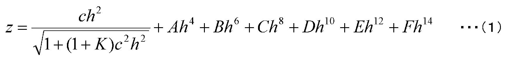
ただし、z:高さhの位置でのz軸方向の変位量(面頂点基準)
h:z軸に対して垂直な方向の高さ(h2=x2+y2)
c:近軸曲率(=1/曲率半径)
A、B、C、D、E、F:
それぞれ4、6、8、10、12、14次の非球面係数
K: 円錐係数
である。また、群間隔におけるWはワイド端、Mは中間倍率、Tはテレ端を表す。
全体諸元
2ω=70°
画面サイズ=4.552mm×3.414mm (Y=2.845mm)
FNO=2.4
ズーム比=2.8倍
F=-4.063mm
L=26.92mm
V端光束の最大光束幅=3.4mm
レンズデータ
m r d nd νd
1 INFINITY 3.4000000 1.51680 64.20
2 INFINITY 0.6017373
3 3.3566724 1.4381623 1.49700 81.61
4 -4.0098956 2.6325521 1.64769 33.84
5 -7.4836021 0.2125802
6 -6.0333656 1.3220721 1.59201 67.02
7 -1.6671657 0.1374810
8 3.2767314 1.4596985 1.84666 23.78
9 0.8197137 0.5179634
10 1.6177176 2.2719648 1.63854 55.45
11 -4.8328802 5.1742651
12 -18.0491558 1.1384586 1.49700 81.61
13 -1.7777505 0.0999860
14 1.4688631 0.8122264 1.56907 71.30
15 1.8766719 0.1363150
16 4.9994891 0.4999910 1.84666 23.78
17 1.6428635 1.6954327
18 3.7928310 1.8395681 1.72916 54.67
19 3.3606612 0.3270049
20 INFINITY 0.3000000 1.51680 64.20
21 INFINITY 0.8998775
非球面係数
m K A B C D E F
3 -8.02E+00 2.77E-02 -1.15E-02 6.62E-03 -2.61E-03 5.66E-04 -5.17E-05
5 -1.80E+01 -9.66E-04 3.89E-04 4.52E-04 -1.37E-04 1.81E-05 -7.92E-07
6 5.21E-01 5.71E-02 -7.87E-03 2.44E-04 4.42E-05 -3.31E-06 -4.02E-08
7 -3.40E+00 6.48E-02 -6.52E-03 -2.66E-03 7.10E-04 -6.39E-05 1.97E-06
8 -4.73E-01 -1.11E-02 5.10E-03 -4.50E-03 1.04E-03 -1.01E-04 3.68E-06
9 -3.85E+00 2.42E-03 -1.08E-02 2.89E-03 -3.56E-04 2.25E-05 -5.78E-07
10 -6.48E+00 8.83E-03 -5.50E-03 9.69E-04 -8.63E-05 4.09E-06 -8.78E-08
11 -9.32E-01 1.45E-03 2.38E-04 -1.35E-04 1.36E-05 -7.88E-07 1.23E-08
12 -6.98E-01 2.81E-02 -1.63E-02 7.35E-03 -1.84E-03 2.28E-04 -1.31E-05
13 -3.38E+00 -3.64E-03 3.21E-03 -6.07E-04 1.13E-05 -1.73E-06 -7.39E-07
14 -2.95E-01 -3.62E-02 -3.80E-02 3.64E-02 -2.33E-02 6.23E-03 -7.34E-04
15 6.49E-01 -2.21E-01 3.41E-02 1.39E-02 -1.74E-02 5.63E-03 -1.28E-03
16 9.05E+00 2.01E-01 -2.14E-01 1.65E-01 -8.65E-02 2.67E-02 -3.70E-03
17 1.17E+00 2.93E-01 -1.63E-01 -4.55E-02 4.94E-01 -8.43E-01 3.77E-01
18 -1.24E+00 -2.22E-02 -2.67E-03 3.45E-03 -8.64E-04 8.84E-05 -3.23E-06
19 -3.83E+00 -2.05E-02 -2.06E-03 1.67E-03 -3.03E-04 2.20E-05 -5.57E-07
群間隔
m W M T
2 0.6017373 0.5707610 1.6660788
5 0.2125802 2.7359933 3.5105097
11 5.1742651 2.2874673 0.2068006
17 1.6954327 2.0895333 2.3004180
FGi/|F|
i=1(第1群) i=2(第2群) i=3(第3群)
1.3975 1.0297 0.8025
図8は、本実施例の撮像光学系111の断面図である。撮像光学系111は、上記第2の実施の形態で述べた撮像光学系11の実施例である。図8に示すように本実施例の撮像光学系111は、プリズムPの後方に正のパワーを有するレンズ群である第1群G1を備え、第1群G1の後方に正のパワーを有する可動レンズ群である第2群G2、第3群G3を備える。また、第3群G3の後方には、赤外線フィルタIRF、撮像素子50が順に配置されている。絞りSは、プリズムPの後方であって第1群G1の前端(被写体側)に配置されている。
全体諸元
2ω=70°
画面サイズ=4.552mm×3.414mm (Y=2.845mm)
FNO=2.8
ズーム比=2.8倍
F=-4.063mm
L=29.51mm
V端光束の最大光束幅=3.6mm
レンズデータ
m r d nd νd
1 INFINITY 3.6000000 1.51680 64.20
2 INFINITY 0.3305860
3 INFINITY 0.0999981
4 4.7924242 1.1967433 1.49700 81.61
5 -1.0139650 1.7822256 1.56883 56.04
6 -2.0859000 0.6455099
7 22.0437595 2.3410094 1.84666 23.78
8 -8.9968220 1.0534341
9 -0.9485915 1.5898679 1.69680 55.46
10 -1.3216959 0.3701573
11 -5.5587778 3.7374191 1.71300 53.94
12 -8.3626145 4.2411460
13 2.7923560 2.1533553 1.49700 81.61
14 -2.0953558 0.1026413
15 3.5431426 0.5000100 1.70154 41.15
16 1.7026495 0.9547510
17 -0.8004187 0.5014478 1.84666 23.78
18 -1.6741317 0.1064285
19 1.3261020 2.1648015 1.71300 53.94
20 1.8840294 0.8440608
21 INFINITY 0.3000000 1.51680 64.20
22 INFINITY 0.8992454
非球面係数
m K A B C D E F
4 5.86E+00 -1.59E-02 2.33E-02 -4.54E-02 3.87E-02 4.66E-03 -5.08E-03
6 -4.37E+00 -5.46E-02 2.46E-02 -1.17E-02 3.39E-03 -5.29E-04 3.46E-05
7 2.33E+00 -2.75E-03 6.95E-03 -3.62E-03 1.16E-03 -1.87E-04 1.11E-05
8 4.92E+00 -1.13E-02 -3.32E-03 1.47E-03 1.55E-04 2.68E-05 9.25E-07
9 -6.25E+00 -1.60E-01 3.50E-02 6.39E-03 -3.40E-03 4.85E-04 -2.49E-05
10 -7.42E-01 4.56E-02 -1.43E-02 4.75E-03 -5.13E-04 1.99E-05 -6.77E-07
11 -4.96E+00 5.29E-02 -9.21E-03 5.97E-04 4.20E-05 -7.27E-06 2.25E-07
12 3.22E-01 -2.41E-03 1.38E-03 -3.86E-04 5.96E-05 -4.22E-06 1.48E-07
13 7.71E-01 -9.56E-03 -3.66E-03 -4.60E-04 -1.74E-04 -3.24E-05 -1.32E-06
14 -5.61E+00 -2.38E-02 2.09E-03 9.00E-06 -5.99E-04 1.92E-04 -1.78E-05
15 3.23E+00 -1.02E-01 -1.47E-03 -3.23E-03 6.35E-03 -2.22E-03 2.09E-04
16 -3.21E-01 -1.74E-01 2.72E-02 -2.11E-02 1.21E-02 -3.18E-03 3.19E-04
17 -4.03E+00 -2.20E-02 8.19E-02 -8.15E-02 3.86E-02 -9.28E-03 8.87E-04
18 -5.26E+00 -2.75E-02 4.79E-02 -1.96E-02 7.19E-03 -1.60E-03 1.16E-04
19 -5.80E+00 2.64E-05 -2.21E-03 -7.48E-04 5.03E-04 -8.98E-05 4.32E-06
20 -4.56E+00 1.08E-03 -1.99E-03 2.98E-04 -4.02E-05 1.87E-06 -1.25E-08
群間隔
m W M T
6 0.6455099 0.2657847 0.5489867
12 4.2411460 2.1822547 0.5402629
20 0.8440608 3.2828722 4.6416292
FGi/|F|
i=1 i=2 i=3
0.8871 1.8302 0.8760
図9は、本実施例の撮像光学系121の断面図である。撮像光学系121は、上記第3の実施の形態で述べた撮像光学系21の実施例である。図9に示すように本実施例の撮像光学系121は、プリズムPの後方に正のパワーを有する可動レンズ群である前群GF(第1群G1及び第2群G2)を備え、前群GFの後方に正のパワーを有する可動レンズ群である後群GR(第3群G3)を備える。また、後群GRの後方には、赤外線フィルタIRF、撮像素子50が順に配置されている。絞りSは、後述する後群GRの第8レンズL32と第9レンズL33の間に配置されている。
全体諸元
2ω=70°
画面サイズ=4.552mm×3.414mm (Y=2.845mm)
FNO=2.8
ズーム比=3.5倍
F=-4.063mm
L=30.00mm
V端光束の最大光束幅=4.0mm
レンズデータ
m r d nd νd
1 INFINITY 4.0000000 1.51680 64.20
2 INFINITY 2.0673045
3 9.9477904 0.9212518 1.49700 81.61
4 -36.1123533 0.1000025
5 6.3334788 1.3906934 1.49700 81.61
6 -2.4044545 0.3334809
7 -1.1217234 0.5008360 1.72342 37.99
8 -2.1548331 0.2165537
9 -2.5629226 1.1731649 1.49700 81.61
10 -1.6527482 0.1045501
11 6.8469867 1.4355780 1.84666 23.78
12 4.0597291 1.9011653
13 18.7278772 4.0768226 1.53996 59.71
14 -5.5495381 4.1993310
15 -1.4154655 0.6505659 1.59201 67.02
16 -2.1666633 0.1052542
17 1.0036680 0.9831631 1.49700 81.61
18 -7.4708328 0.1000043
19 INFINITY 0.1365020
20 -3.3754276 0.6039223 1.72047 34.72
21 3.5940007 0.7270050
22 6.8135537 0.0799373 1.50137 56.41
23 -2.1974635 0.2257846
24 INFINITY 0.3000000 1.51680 64.20
25 INFINITY 0.6671757
非球面係数
m K A B C D E F
3 2.88E+00 -3.73E-03 3.58E-03 -2.02E-03 5.03E-04 -5.61E-05 2.18E-06
4 -2.94E+00 -4.46E-02 2.20E-02 -7.29E-03 1.41E-03 -1.33E-04 4.72E-06
5 -4.16E+00 -2.14E-02 8.58E-03 -3.11E-03 5.92E-04 -4.89E-05 1.44E-06
6 -7.33E-01 4.06E-02 -7.89E-03 6.99E-04 -2.42E-06 -2.47E-06 5.44E-08
7 -9.74E-01 1.33E-01 -2.66E-02 3.31E-03 -2.20E-04 3.53E-06 4.22E-08
8 -2.02E+00 1.30E-02 1.56E-02 -4.70E-03 6.18E-04 -4.35E-05 1.32E-06
9 -9.25E+00 -4.18E-02 2.85E-02 -6.27E-03 7.39E-04 -4.79E-05 1.29E-06
10 -1.17E+00 6.22E-02 -1.26E-02 1.43E-03 -9.28E-05 3.98E-06 -1.48E-07
11 -8.54E+00 5.17E-03 7.39E-04 -1.68E-04 -1.35E-05 1.90E-06 -7.83E-08
12 -5.66E+00 -2.04E-02 7.28E-03 -1.31E-03 1.13E-04 -5.02E-06 1.06E-07
13 2.61E+01 1.87E-02 -1.81E-03 5.52E-05 3.14E-06 -2.74E-07 3.89E-09
14 1.37E+00 1.63E-03 1.91E-04 4.43E-05 -8.15E-06 6.27E-07 -1.30E-08
15 -7.11E+00 6.91E-03 -2.27E-02 1.42E-02 -8.10E-03 2.13E-03 -1.96E-04
16 3.71E-01 3.52E-02 -7.12E-03 4.70E-04 -3.17E-04 3.29E-04 -3.14E-05
17 -4.39E-01 -1.94E-01 1.08E-01 -1.33E-01 7.51E-02 -3.19E-02 5.14E-03
18 1.14E+00 -4.34E-02 8.27E-02 -7.08E-02 4.05E-02 -1.32E-02 3.59E-03
20 -6.13E-01 1.59E-01 -2.11E-02 -3.58E-03 -1.18E-02 6.10E-02 -3.04E-02
21 -8.20E+00 1.99E-01 1.01E-01 -3.48E-01 5.66E-01 -3.64E-01 1.06E-01
22 1.57E+00 -3.54E-02 -2.31E-02 3.26E-02 -2.89E-02 9.94E-03 -1.25E-03
23 -2.51E+01 4.13E-02 -2.63E-02 5.87E-03 -8.81E-04 6.04E-05 -2.53E-06
群間隔
m W M T
2 2.0673045 2.1761626 0.6046647
14 4.1993310 1.0074333 0.3470603
23 0.2257846 3.3088577 5.5410009
FGi/|F|
i=F i=R
1.5924 0.8334
図10は、本実施例の撮像光学系131の断面図である。撮像光学系131は、上記第2の実施の形態で述べた撮像光学系11の実施例である。図10に示すように本実施例の撮像光学系131は、プリズムPの後方に正のパワーを有する可動レンズである第1レンズL11(第1群G1)を備え、第1レンズL11の後方に正のパワーを有する可動レンズ群である第2群G2及び第3群G3を備える。また、第3群G3の後方には、固定レンズL41が配置され、固定レンズL41の後方に赤外線フィルタIRF、撮像素子50が順に配置されている。絞りSは、プリズムPの後面に形成されている。
全体諸元
2ω=70°
画面サイズ=4.552mm×3.414mm (Y=2.845mm)
FNO=2.8
ズーム比=2.8倍
F=-4.063mm
L=30.00mm
V端光束の最大光束幅=3.4mm
レンズデータ
m r d nd νd
1 INFINITY 3.4000000 1.51680 64.20
2 INFINITY 0.4858325
3 3.8517890 4.2194283 1.49700 81.61
4 -5.3748003 0.3396133
5 -1.7752715 1.0300928 1.53116 56.15
6 -1.2735683 0.1000007
7 3.0621640 2.1620967 1.82114 24.06
8 0.7764885 0.3208142
9 1.2536618 2.7237377 1.53116 56.15
10 -3.5719440 6.1767027
11 2.6291686 2.7485971 1.49700 81.61
12 -2.2742430 0.1032998
13 5.4230279 0.5686936 1.53116 56.15
14 11.4652752 0.1363856
15 -4.9123687 0.6824105 1.82114 24.06
16 7.3044061 1.2233549
17 5.2564762 1.8371709 1.53116 56.15
18 2.0971204 0.5402834
19 INFINITY 0.3000000 1.51680 64.20
20 INFINITY 0.8989604
非球面係数
m K A B C D E F
3 -1.26E+01 2.63E-02 -8.65E-03 1.86E-03 7.74E-05 1.69E-04 -9.91E-05
4 -2.29E+01 -1.33E-02 5.81E-03 -1.15E-03 1.08E-04 -6.02E-07 -1.36E-07
5 -2.30E+00 6.81E-02 -9.85E-03 -1.92E-04 3.40E-04 -4.32E-05 1.45E-06
6 -1.79E+00 3.93E-02 2.29E-03 -3.85E-03 9.13E-04 -8.65E-05 2.84E-06
7 -6.55E+00 1.82E-02 -5.91E-03 4.38E-04 2.42E-05 -4.58E-06 -4.55E-09
8 -3.42E+00 -1.42E-02 7.06E-04 3.72E-04 -6.95E-05 4.34E-06 -1.09E-07
9 -6.09E+00 -1.36E-02 4.59E-03 -6.04E-04 4.14E-05 -1.56E-06 2.81E-08
10 -5.94E+00 -1.47E-02 1.98E-03 -2.40E-04 1.38E-05 8.40E-09 -2.41E-09
11 8.98E-01 -1.33E-02 -7.87E-03 4.25E-03 -2.74E-03 5.85E-04 -4.94E-05
12 -5.66E+00 -1.81E-02 -1.75E-02 1.87E-02 -9.28E-03 2.28E-03 -2.01E-04
13 3.75E+00 -4.30E-02 -6.91E-02 6.02E-02 -2.42E-02 5.81E-03 -5.29E-04
14 4.72E+01 -8.82E-02 7.33E-03 -2.39E-02 1.92E-02 -5.41E-03 5.78E-04
15 1.11E+01 1.21E-01 -3.25E-02 -2.89E-02 1.91E-02 -4.07E-03 1.37E-04
16 -6.57E+00 1.18E-01 2.52E-03 -4.81E-02 2.27E-02 -5.16E-03 5.26E-04
17 -5.85E+00 -2.00E-02 -1.94E-03 1.51E-03 -1.35E-04 -7.00E-05 4.41E-06
18 -3.44E+00 -2.15E-02 1.59E-03 2.79E-04 -9.96E-05 7.62E-06 -2.15E-07
群間隔
m W M T
4 0.3396133 1.8739271 2.4574254
10 6.1767027 3.2529403 1.7912946
16 1.2233549 2.6129363 3.4912232
FGi/|F|
i=1 i=2 i=3
1.3067 1.1499 0.9284
図11は、本実施例の撮像光学系141の断面図である。撮像光学系141は、上記第1の実施の形態で述べた撮像光学系1の実施例である。図11に示すように本実施例の撮像光学系141は、プリズムPの後方に順に正のパワーを有する可動レンズ群である第1群G1、第2群G2、第3群G3を備える。また、第3群G3の後方には、赤外線フィルタIRF、撮像素子50が順に配置されている。絞りSは、第1群G1の前端(被写体側)に配置されている。
全体諸元
2ω=70°
画面サイズ=4.552mm×3.414mm (Y=2.845mm)
FNO=2.8
ズーム比=2.8倍
F=-4.063mm
L=29.83mm
V端光束の最大光束幅=3.6mm
レンズデータ
m r d nd νd
1 INFINITY 3.6000000 1.51680 64.20
2 INFINITY 0.3798570
3 INFINITY 0.0999985
4 4.8388758 0.5000007 1.82080 42.71
5 2.6646485 0.1362892
6 5.4646156 1.3860729 1.49700 81.61
7 -1.5641059 0.1017730
8 -2.7956111 1.1889590 1.63219 23.42
9 -3.4182768 0.4375511
10 -123.2294313 3.3035354 1.85135 40.10
11 -4.3611938 1.2930171
12 -0.6692682 2.4326163 1.53116 56.15
13 -1.3616053 0.1498654
14 -4.4292473 2.9041824 1.58547 29.90
15 -10.7439359 3.7525477
16 3.9147966 0.9428957 1.49700 81.61
17 -4.2056110 0.1016232
18 4.6754001 0.9514837 1.49700 81.61
19 56.7714551 0.1284992
20 -10.1867797 0.9198267 1.80610 33.27
21 4.1504703 0.7086235
22 2.1446065 2.4254184 1.53116 56.15
23 10.1449975 0.4012059
24 INFINITY 0.3000000 1.51680 64.20
25 INFINITY 1.2822941
非球面係数
m K A B C D E F
4 -4.57E+00 -6.62E-02 -1.06E-01 4.19E-01 -8.37E-01 8.01E-01 -2.81E-01
5 8.15E-01 -1.19E-01 6.30E-02 -1.22E-01 1.83E-01 -1.11E-01 2.11E-02
6 1.37E+00 -3.88E-02 2.03E-02 -4.38E-02 8.10E-02 -4.68E-02 7.51E-03
7 -3.11E-01 -3.09E-03 1.37E-02 -2.40E-02 1.44E-02 -3.93E-03 3.36E-04
8 -2.02E+00 -3.02E-02 5.97E-03 -2.21E-02 1.23E-02 -3.00E-03 2.26E-04
9 -2.99E-01 -8.48E-03 2.65E-03 -3.65E-03 1.30E-03 -1.90E-04 1.06E-05
10 -2.41E-01 2.63E-03 9.87E-05 -1.12E-04 8.78E-06 1.99E-06 -8.08E-08
11 6.23E-02 1.23E-02 -9.43E-03 2.73E-03 -4.10E-04 3.84E-05 -1.64E-06
12 -3.21E+00 1.01E-02 -1.28E-02 6.24E-03 -2.07E-03 3.20E-04 -1.44E-05
13 -1.22E+00 3.61E-02 -9.56E-03 1.39E-03 -9.22E-05 2.15E-06 -4.19E-08
14 1.98E+00 4.38E-02 -3.83E-03 5.66E-05 1.05E-04 -1.57E-05 5.39E-07
15 2.31E+00 -1.03E-02 3.28E-03 -9.31E-04 1.39E-04 -1.21E-05 4.68E-07
16 -2.43E+00 -2.88E-03 -1.68E-03 7.24E-04 -9.04E-04 2.31E-04 -1.79E-05
17 -1.26E+01 -4.37E-03 5.44E-05 -1.38E-03 4.36E-04 -5.82E-05 3.08E-06
18 -1.92E+00 9.39E-03 -4.53E-03 7.01E-04 4.18E-04 -9.42E-05 5.62E-06
19 2.43E-01 -3.32E-02 5.30E-03 2.29E-04 -7.78E-04 2.54E-04 -1.14E-05
20 1.07E+01 8.61E-03 3.06E-03 -1.32E-03 -5.07E-04 2.80E-04 -1.77E-05
21 5.17E+00 -1.75E-02 1.64E-02 -7.22E-03 1.75E-04 2.99E-04 -2.86E-05
22 -2.14E+00 -1.95E-02 5.32E-03 -1.79E-03 2.32E-04 -6.22E-05 4.50E-06
23 3.57E+00 3.05E-02 -6.30E-03 5.81E-04 -1.09E-04 1.04E-05 -2.94E-07
群間隔
m W M T
2 0.3798570 1.3377592 0.3810934
9 0.4375511 0.3095757 0.2003101
15 3.7525477 0.8314666 0.1997644
23 0.4012059 2.4921402 4.1903461
FGi/|F|
i=1 i=2 i=3
1.0480 6.8326 0.9020
図12は、本実施例の撮像光学系151の断面図である。撮像光学系151は、上記第4の実施の形態で述べた撮像光学系31の実施例である。図12に示すように本実施例の撮像光学系151は、プリズムPの後方に正のパワーを有する可動レンズ群である第1群G1を備え、第1群G1の後方に正のパワーを有した固定レンズ群である第2群G2を備え、第2群G2の後方に正のパワーを有した可動レンズ群である第3群G3を備える。また、第3群G3の後方には、赤外線フィルタIRF、撮像素子50が順に配置されている。絞りSは、後述する第3群G3の第7レンズL32と第8レンズL33の間に配置されている。
全体諸元
2ω=70°
画面サイズ=4.552mm×3.414mm (Y=2.845mm)
FNO=2.8
ズーム比=2.8倍
F=-4.063mm
L=30.00mm
V端光束の最大光束幅=4.0mm
レンズデータ
m r d nd νd
1 INFINITY 4.0000000 1.51680 64.20
2 INFINITY 2.2079141
3 4.5739477 5.4175497 1.49700 81.61
4 -2.2511763 0.1727827
5 2.0253995 0.6387439 1.84666 23.78
6 1.2694701 0.7177441
7 6.8499487 1.6255997 1.77250 49.62
8 -1.3308872 0.1137200
9 -1.6696705 0.5000027 1.60342 38.01
10 1.0810322 0.4868751
11 3.8286203 0.5000024 1.78590 43.93
12 -15.7065932 4.2702072
13 5.2991206 3.4398664 1.49700 81.61
14 -2.4270075 0.1000662
15 2.0194998 0.6982299 1.49700 81.61
16 12.7949216 0.1061898
17 INFINITY 0.0999981
18 6.0595334 0.4999981 1.76182 26.61
19 1.4481098 1.4629164
20 1.7256007 0.9734905 1.61881 63.85
21 1.4800396 0.7678123
22 INFINITY 0.3000000 1.51680 64.20
23 INFINITY 0.9000385
非球面係数
m K A B C D E F
3 1.11E+00 -2.55E-03 -1.77E-04 -4.26E-06 -3.23E-06 3.81E-07 -3.25E-08
4 -4.81E+00 -4.61E-03 -7.13E-04 4.61E-04 -8.23E-05 6.44E-06 -1.85E-07
5 -5.52E-01 -2.55E-02 -5.41E-03 1.15E-03 -6.53E-05 -2.53E-06 1.21E-07
6 -1.48E+00 -4.68E-02 2.72E-03 7.71E-04 -1.60E-04 1.13E-05 -2.92E-07
7 -3.91E+00 -9.28E-03 6.02E-03 -7.51E-04 1.38E-05 1.07E-06 -2.23E-08
8 -7.84E+00 2.04E-02 5.45E-04 -8.04E-05 -3.14E-05 2.48E-06 -5.62E-08
9 -1.68E+01 1.71E-02 -2.75E-03 5.57E-04 3.86E-06 -4.87E-06 1.14E-07
10 -3.67E+00 -1.11E-02 -3.27E-03 1.67E-04 -1.33E-05 6.32E-06 -1.75E-07
11 -7.45E+00 1.87E-02 -1.57E-02 2.18E-03 -1.08E-04 4.68E-06 -1.08E-07
12 -5.41E+00 2.15E-02 -1.26E-02 2.44E-03 -1.30E-04 -1.52E-06 5.60E-08
13 5.07E+00 -1.19E-02 -3.51E-03 1.09E-03 -3.97E-04 9.00E-05 -7.23E-06
14 -7.19E+00 -6.15E-02 2.48E-02 -5.97E-03 6.83E-04 -3.23E-06 1.95E-06
15 7.77E-01 -2.48E-02 -5.56E-02 6.95E-02 -7.44E-02 3.43E-02 -6.31E-03
16 3.79E+00 -1.05E-01 2.06E-01 -3.07E-01 2.26E-01 -8.64E-02 1.34E-02
18 6.98E+00 -1.99E-01 4.26E-01 -4.80E-01 2.98E-01 -9.00E-02 9.59E-03
19 6.53E-01 -2.95E-01 5.13E-01 -7.46E-01 6.39E-01 -3.05E-01 4.15E-02
20 -1.29E+00 -6.30E-02 4.84E-03 2.18E-03 -1.07E-03 1.65E-04 -9.77E-06
21 -1.04E+00 -8.39E-02 1.48E-02 -1.21E-03 -1.14E-04 1.76E-05 -5.16E-07
群間隔
m W M T
2 2.2079141 1.2393953 0.4227260
6 0.7177441 1.6862628 2.5029321
12 4.2702072 2.2317523 1.0310578
21 0.7678123 2.8062671 4.0069616
FGi/|F|
i=1 i=2 i=3
1.1555 1.9806 0.6513
(実施例7)
図13は、本実施例の撮像光学系161の断面図である。撮像光学系161は、上記第5の実施の形態で述べた撮像光学系41の実施例である。図13に示すように本実施例の撮像光学系161は、プリズムPの後方に正のパワーを有する可動レンズ群である第1群G1を備え、第1群G1の後方に正のパワーを有した固定レンズ群である第2群G2を備え、第2群G2の後方に正のパワーを有した可動レンズ群である第3群G3を備える。また、第3群G3の後方には、赤外線フィルタIRF、撮像素子50が順に配置されている。絞りSは、プリズムPの後面に配置されている。
全体諸元
2ω=70°
画面サイズ=4.552mm×3.414mm (Y=2.845mm)
FNO=2.8
ズーム比=2.8倍
F=-4.063mm
L=30.00mm
V端光束の最大光束幅=4.0mm
レンズデータ
m r d nd νd
1 INFINITY 4.0000000 1.51680 64.20
2 INFINITY 2.1462235
3 12.6001285 1.8618164 1.49700 81.61
4 -2.4284901 0.1000558
5 5.1981612 0.8151989 1.72916 54.67
6 4.0406229 0.1317719
7 6.1672123 0.5000621 1.84666 23.78
8 2.5408776 0.6178767
9 7.0903482 2.0309815 1.72916 54.67
10 -1.0205849 0.0999677
11 2.0981862 0.5002233 1.84666 23.78
12 0.6066385 0.6924815
13 1.8469872 1.5414085 1.83400 37.34
14 -4.7293457 2.7002593
15 -1.2056392 0.5003516 1.69895 30.05
16 5.2124305 0.1017965
17 5.6816834 1.1506070 1.72916 54.67
18 -2.6666111 0.0999953
19 1.8941035 5.6019242 1.49700 81.61
20 -10.9930092 3.3309219
21 INFINITY 0.3000000 1.51680 64.20
22 INFINITY 1.1735813
非球面係数
m K A B C D E F
3 5.98E+00 -4.41E-03 -7.71E-03 1.97E-03 -1.37E-04 -6.81E-06 5.21E-07
4 -1.16E-01 -5.61E-04 -1.53E-03 -1.87E-04 1.72E-04 -1.75E-05 5.97E-07
5 1.57E+00 -3.55E-02 2.75E-03 -1.57E-04 3.38E-05 -2.42E-06 3.76E-08
6 1.06E+00 -7.31E-02 1.31E-02 -2.48E-03 3.04E-04 -1.91E-05 5.35E-07
7 3.32E+00 -4.80E-02 6.06E-03 -1.04E-03 1.41E-04 -9.36E-06 3.08E-07
8 -8.13E-01 -2.88E-02 3.10E-03 -2.43E-04 -4.12E-06 2.00E-06 -4.74E-08
9 3.03E+00 -2.37E-03 -4.86E-03 1.04E-03 -9.09E-05 4.25E-06 -8.59E-08
10 -4.63E+00 -4.81E-03 -1.96E-03 4.36E-04 -2.27E-05 4.54E-07 2.84E-09
11 -1.16E+01 -5.12E-02 1.81E-02 -2.13E-03 1.08E-04 -2.70E-06 5.38E-08
12 -2.40E+00 -5.94E-02 2.02E-02 -1.93E-03 -8.55E-05 1.99E-05 -6.24E-07
13 -1.98E+01 4.41E-02 -1.34E-02 1.89E-03 -9.73E-05 1.37E-06 -2.88E-08
14 -6.18E+00 5.78E-03 2.74E-03 -1.30E-03 2.79E-04 -2.63E-05 9.19E-07
15 -8.56E-01 7.68E-02 -5.10E-02 4.08E-02 -1.72E-02 3.54E-03 -2.93E-04
16 -1.75E+01 -4.66E-02 -1.47E-03 1.33E-02 -5.40E-03 8.69E-04 -5.00E-05
17 -1.95E-01 -4.35E-02 5.03E-03 4.24E-03 -2.03E-03 3.50E-04 -2.08E-05
18 -1.60E+00 -2.80E-04 9.32E-04 -2.10E-05 -3.07E-04 8.12E-05 -5.27E-06
19 -9.59E-01 -8.20E-03 1.63E-03 -2.44E-04 -6.22E-05 3.61E-05 -4.59E-06
20 4.92E+00 1.37E-03 2.10E-02 -1.82E-02 1.01E-02 -2.50E-03 2.43E-04
群間隔
m W M T
2 2.1462235 0.7959062 0.1997339
8 0.6178767 1.9681939 2.5643663
14 2.7002593 1.3499421 0.7537697
20 3.3309219 4.6812391 5.2774115
FGi/|F|
i=1 i=2 i=3
2.1442 0.5529 0.7597
図14は、本実施例の撮像光学系171の断面図である。この断面図における各レンズの有効径は、V端の光束に対応するものである。また、撮像素子50の中心(画面の中心)に投影される光線束と、上下のV端の光線束と、を表示している。撮像光学系171は、上記第1の実施の形態で述べた撮像光学系1の実施例である。
全体諸元
2ω=70°
画面サイズ=4.950mm×2.788mm (Y=2.845mm)
FNO=2.8
ズーム比=2.8倍
F=-4.063mm
L=28.67mm
V端光束の最大光束幅=3.2mm
レンズデータ
m r d nd νd
1 INFINITY 0.3000000 1.51680 64.20
2 INFINITY 1.6000000
3 INFINITY 2.9730580
4 4.9818867 1.1575082 1.49700 81.61
5 -3.0561432 0.1000132
6 -6.2134953 2.8223455 1.52855 76.98
7 -0.6917349 1.0495017 1.51742 52.15
8 -8.6915278 0.4337890
9 -32.7117591 1.4047689 1.84666 23.78
10 -4.2995937 0.1004266
11 1.1376078 0.5858766 1.85135 40.10
12 0.6341717 1.4652108
13 28.0080988 3.0664414 1.56907 71.30
14 -4.2278748 2.9871782
15 13.1884841 1.8791152 1.49700 81.61
16 -8.2315354 0.1001129
17 1.6754824 0.8633798 1.49700 81.61
18 -11.7006078 0.1028934
19 INFINITY 0.1652987
20 -7.5423713 1.1681193 1.85026 32.27
21 3.2224631 1.1030914
22 1.6331296 1.2526082 1.59240 68.30
23 1.6905282 0.7882906
24 INFINITY 0.3000000 1.51680 64.20
25 INFINITY 0.9000528
非球面係数
m K A B C D E F
4 5.56E-01 -2.51E-04 -2.95E-03 4.78E-04 4.09E-05 -1.62E-05 9.63E-07
5 -1.29E+00 2.07E-02 -6.09E-03 1.30E-03 5.83E-05 -4.21E-05 2.94E-06
6 -4.26E-01 2.18E-02 -6.13E-03 2.67E-03 -5.17E-04 4.50E-05 -1.46E-06
7 -1.68E+00 1.19E-02 -1.25E-02 5.61E-04 4.54E-04 -6.71E-05 2.72E-06
8 -1.34E+00 9.33E-04 7.11E-04 -1.83E-04 6.18E-05 -6.22E-06 1.95E-07
9 2.22E+00 2.76E-02 -2.58E-03 -1.38E-04 7.25E-05 -7.49E-06 1.81E-07
10 -2.74E+00 4.54E-02 -5.73E-03 -4.08E-04 1.42E-04 -1.11E-05 2.65E-07
11 -9.34E-01 -8.02E-02 2.72E-02 -7.25E-03 6.92E-04 -1.42E-05 4.28E-07
12 -2.01E+00 -9.21E-03 6.75E-03 -2.46E-03 -2.64E-04 1.20E-04 -4.64E-06
13 -5.01E+00 3.13E-03 -3.06E-03 4.92E-04 -1.94E-04 4.06E-05 -1.48E-06
14 6.43E-01 2.18E-03 -4.16E-04 1.83E-05 2.00E-05 -2.92E-06 9.43E-08
15 1.97E+00 8.05E-03 -8.22E-03 3.80E-03 -1.60E-03 3.96E-04 -3.52E-05
16 -8.62E+00 -4.50E-02 2.16E-02 -1.93E-02 1.03E-02 -2.52E-03 2.25E-04
17 4.47E-01 -6.80E-02 -3.61E-02 4.94E-02 -7.41E-02 3.27E-02 -6.08E-03
18 -2.39E+00 -6.38E-02 8.68E-02 -1.02E-01 3.71E-02 -9.34E-04 -1.18E-03
20 -1.04E+01 -5.19E-02 1.41E-01 -1.23E-01 5.85E-02 -1.21E-02 1.25E-03
21 4.14E+00 -6.21E-02 1.27E-01 -7.35E-02 2.74E-03 2.50E-02 -8.70E-03
22 -3.83E+00 -4.35E-04 -1.43E-02 4.90E-03 -5.70E-04 1.62E-05 -4.14E-07
23 -7.71E-01 -5.80E-02 2.26E-03 6.82E-04 -1.39E-04 6.86E-06 -1.72E-07
群間隔
m W M T
3 2.9730580 3.1311670 2.0274400
8 0.4337890 0.2141259 0.1669172
14 2.9871782 0.8205715 0.2005387
23 0.7882906 3.0169956 4.7882534
FGi/|F|
i=1 i=2 i=3
1.1743 2.6418 0.7947
以上の実施例をまとめると、第1の実施の形態で述べた撮像光学系1の実施例は、実施例1、実施例5、及び実施例8である。また、第2の実施の形態で述べた撮像光学系11の実施例は、実施例2と実施例4である。さらに、第3の実施の形態で述べた撮像光学系21の実施例は、実施例3、第4の実施の形態で述べた撮像光学系31の実施例は、実施例6、第5の実施の形態で述べた撮像光学系41の実施例は、実施例7である。
最小値 最大値
第1群G1 0.8871 2.1442
第2群G2 0.5529 6.8326
第3群G3 0.6513 0.9284
50 撮像素子
G1 第1群
G2 第2群
G3 第3群
GF 前群
GR 後群
PL 防護ガラス
IRF 赤外線フィルタ
P プリズム
REF ミラー
S 絞り
II 中間像
O 中心軸
Claims (17)
- 倍率調整を可能とする倍率調整機能を備えた撮像光学系であって、
被写体側に、光軸を折曲げる機能を有した光軸折曲手段が配置され、
前記光軸折曲手段の後方に順に、実像である中間像を生成する正のパワーを有した第1群と、
軸外光束の方向を中心軸側に屈折させる正のパワーを有した第2群と、
前記中間像を撮像素子に結像させる正のパワーを有した第3群と、
を少なくとも備えたことを特徴とする撮像光学系。 - 前記光軸折曲手段は、被写体方向と前記撮像素子の短方向とが平行となるように前記光軸を折曲げる機能を有していることを特徴とする請求項1に記載の撮像光学系。
- 前記光軸折曲手段は、プリズム又はミラーであることを特徴とする請求項1又は請求項2に記載の撮像光学系。
- 前記第1群、前記第2群、前記第3群は、一枚のレンズ、又は、レンズ群により構成されていることを特徴とする請求項1乃至請求項3のいずれか1項に記載の撮像光学系。
- 少なくとも前記第3群が前記倍率調整のために可動とされたことを特徴とする請求項1乃至請求項4のいずれか1項に記載の撮像光学系。
- 前記第1群、前記第2群、前記第3群で前記倍率調整を行うことを特徴とする請求項1乃至請求項5のいずれか1項に記載の撮像光学系。
- 前記第2群及び前記第3群で前記倍率調整を行うことを特徴とする請求項1乃至請求項5のいずれか1項に記載の撮像光学系。
- 前記第1群及び前記第3群で前記倍率調整を行うことを特徴とする請求項1乃至請求項5のいずれか1項に記載の撮像光学系。
- 焦点調整を行う焦点調整機能を備えたことを特徴とする請求項1乃至請求項8のいずれか1項に記載の撮像光学系。
- 前記第1群が焦点調整のために可動とされたことを特徴とする請求項1乃至請求項9のいずれか1項に記載の撮像光学系。
- 前記第1群と前記第3群が連結され、連動して移動することにより前記倍率調整を行うことを特徴とする請求項1乃至請求項5のいずれか1項に記載の撮像光学系。
- 各群の焦点距離をワイド端での全体の焦点距離の絶対値で割った値は、
前記第1群が、最小で0.5、最大で3.0、
前記第2群が、0.5以上、
前記第3群が、最小で0.5、最大で1.5
の範囲内にあることを特徴とする請求項1乃至請求項11のいずれか1項に記載の撮像光学系。 - 前記第1群と前記第2群との距離が固定されて前群を構成し、前記第3群が後群を構成し、前記前群と後群とで前記倍率調整を行うことを特徴とする請求項1乃至請求項5のいずれか1項に記載の撮像光学系。
- 前記前群が焦点調整のために可動とされたことを特徴とする請求項13に記載の撮像光学系。
- 各群の焦点距離をワイド端での焦点距離の絶対値で割った値は、
前記前群が、最小で0.5、最大で3.0、
前記後群が、最小で0.5、最大で1.5
の範囲内にあることを特徴とする請求項13又は請求項14に記載の撮像光学系。 - 前記第1群の前方、及び又は、前記第3群の後方に固定レンズ、又は、固定レンズ群を配置したことを特徴とする請求項1乃至請求項15のいずれか1項に記載の撮像光学系。
- 前記光軸折曲手段の前方に光学部品を配置したことを特徴とする請求項1乃至請求項16のいずれか1項に記載の撮像光学系。
Priority Applications (4)
| Application Number | Priority Date | Filing Date | Title |
|---|---|---|---|
| EP13875153.2A EP2933672B1 (en) | 2013-02-15 | 2013-11-15 | Imaging optics |
| KR1020157021154A KR101707874B1 (ko) | 2013-02-15 | 2013-11-15 | 촬상 광학계 |
| CN201380071198.6A CN104937471B (zh) | 2013-02-15 | 2013-11-15 | 光学成像系统 |
| US14/762,865 US9488812B2 (en) | 2013-02-15 | 2013-11-15 | Imaging optics |
Applications Claiming Priority (2)
| Application Number | Priority Date | Filing Date | Title |
|---|---|---|---|
| JP2013027423A JP5924542B2 (ja) | 2013-02-15 | 2013-02-15 | 撮像光学系 |
| JP2013-027423 | 2013-02-15 |
Publications (1)
| Publication Number | Publication Date |
|---|---|
| WO2014125533A1 true WO2014125533A1 (ja) | 2014-08-21 |
Family
ID=51353573
Family Applications (1)
| Application Number | Title | Priority Date | Filing Date |
|---|---|---|---|
| PCT/JP2013/006714 WO2014125533A1 (ja) | 2013-02-15 | 2013-11-15 | 撮像光学系 |
Country Status (7)
| Country | Link |
|---|---|
| US (1) | US9488812B2 (ja) |
| EP (1) | EP2933672B1 (ja) |
| JP (1) | JP5924542B2 (ja) |
| KR (1) | KR101707874B1 (ja) |
| CN (1) | CN104937471B (ja) |
| TW (1) | TW201502571A (ja) |
| WO (1) | WO2014125533A1 (ja) |
Families Citing this family (6)
| Publication number | Priority date | Publication date | Assignee | Title |
|---|---|---|---|---|
| JP6341275B2 (ja) * | 2014-05-09 | 2018-06-13 | 株式会社ニコン | 倒立等倍リレーレンズ、カメラシステム、および中間アダプタ |
| JP6029159B1 (ja) | 2016-05-13 | 2016-11-24 | 株式会社タムロン | 観察光学系、観察撮像装置、観察撮像システム、結像レンズ系及び観察光学系の調整方法 |
| TWI676835B (zh) * | 2018-09-26 | 2019-11-11 | 大陸商信泰光學(深圳)有限公司 | 廣角鏡頭(十七) |
| CN111123490B (zh) * | 2019-12-30 | 2022-08-16 | Oppo广东移动通信有限公司 | 变焦镜头、成像模组和电子设备 |
| CN113552696B (zh) * | 2021-07-15 | 2023-11-07 | 江西晶超光学有限公司 | 光学系统、取像模组及电子设备 |
| WO2023243154A1 (ja) * | 2022-06-16 | 2023-12-21 | パナソニックIpマネジメント株式会社 | 光学系、画像投写装置および撮像装置 |
Citations (10)
| Publication number | Priority date | Publication date | Assignee | Title |
|---|---|---|---|---|
| JP2003043354A (ja) | 2001-05-14 | 2003-02-13 | Olympus Optical Co Ltd | 電子撮像装置 |
| JP2004037966A (ja) | 2002-07-05 | 2004-02-05 | Minolta Co Ltd | 撮像レンズ装置 |
| JP2007086141A (ja) | 2005-09-20 | 2007-04-05 | Konica Minolta Photo Imaging Inc | 撮像光学ユニットおよび撮像装置 |
| JP2007155948A (ja) | 2005-12-02 | 2007-06-21 | Jihei Nakagawa | ズームレンズ |
| JP2009192785A (ja) * | 2008-02-14 | 2009-08-27 | Fujifilm Corp | ズームレンズ |
| JP2010134286A (ja) * | 2008-12-05 | 2010-06-17 | Sharp Corp | 組合せレンズ、撮像装置および電子機器 |
| JP2011007824A (ja) * | 2009-06-23 | 2011-01-13 | Canon Inc | 光学装置 |
| JP2011130014A (ja) * | 2009-12-15 | 2011-06-30 | Canon Inc | 撮像装置 |
| JP2013033283A (ja) * | 2011-07-05 | 2013-02-14 | Nitto Kogaku Kk | 投射光学系およびプロジェクタ装置 |
| WO2013129274A1 (ja) * | 2012-03-02 | 2013-09-06 | コニカミノルタ株式会社 | コンバータレンズ及び撮像光学系 |
Family Cites Families (15)
| Publication number | Priority date | Publication date | Assignee | Title |
|---|---|---|---|---|
| JP3395801B2 (ja) * | 1994-04-28 | 2003-04-14 | 株式会社ニコン | 反射屈折投影光学系、走査型投影露光装置、及び走査投影露光方法 |
| JPH11119119A (ja) * | 1997-10-08 | 1999-04-30 | Asahi Optical Co Ltd | リレー式実像ファインダー光学系 |
| US7436599B2 (en) * | 2001-05-14 | 2008-10-14 | Olympus Corporation | Electronic image pickup system |
| US7283309B2 (en) * | 2004-08-20 | 2007-10-16 | Panavision International, L.P. | Wide-range, wide-angle, rotatable compound zoom |
| JP2006078702A (ja) * | 2004-09-08 | 2006-03-23 | Canon Inc | ズーム光学系 |
| US7227682B2 (en) * | 2005-04-08 | 2007-06-05 | Panavision International, L.P. | Wide-range, wide-angle compound zoom with simplified zooming structure |
| US7768715B2 (en) * | 2007-02-21 | 2010-08-03 | Theia Technologies, Llc | Whole system zoom and varifocal lens with intermediate image |
| JP2009251203A (ja) * | 2008-04-04 | 2009-10-29 | Olympus Corp | 撮像装置 |
| JP5536394B2 (ja) | 2008-08-29 | 2014-07-02 | 株式会社日本触媒 | フタロシアニン化合物 |
| TWI406005B (zh) * | 2009-02-24 | 2013-08-21 | Asia Optical Co Inc | 小型化變焦鏡頭及影像擷取裝置 |
| CN102043229B (zh) * | 2009-10-15 | 2012-05-23 | 扬明光学股份有限公司 | 定焦镜头 |
| TWI420138B (zh) * | 2010-07-29 | 2013-12-21 | Young Optics Inc | 變焦鏡頭 |
| TW201209471A (en) * | 2010-08-30 | 2012-03-01 | Young Optics Inc | Lens module |
| TWI460466B (zh) * | 2010-11-09 | 2014-11-11 | Asia Optical Co Inc | Zoomable short focus projection lens |
| JP5871743B2 (ja) * | 2012-07-31 | 2016-03-01 | キヤノン株式会社 | 結像光学系、及びそれを用いた投射型画像表示装置、撮像装置 |
-
2013
- 2013-02-15 JP JP2013027423A patent/JP5924542B2/ja active Active
- 2013-11-15 KR KR1020157021154A patent/KR101707874B1/ko active IP Right Grant
- 2013-11-15 CN CN201380071198.6A patent/CN104937471B/zh active Active
- 2013-11-15 EP EP13875153.2A patent/EP2933672B1/en not_active Not-in-force
- 2013-11-15 WO PCT/JP2013/006714 patent/WO2014125533A1/ja active Application Filing
- 2013-11-15 US US14/762,865 patent/US9488812B2/en active Active
-
2014
- 2014-01-17 TW TW103101857A patent/TW201502571A/zh unknown
Patent Citations (10)
| Publication number | Priority date | Publication date | Assignee | Title |
|---|---|---|---|---|
| JP2003043354A (ja) | 2001-05-14 | 2003-02-13 | Olympus Optical Co Ltd | 電子撮像装置 |
| JP2004037966A (ja) | 2002-07-05 | 2004-02-05 | Minolta Co Ltd | 撮像レンズ装置 |
| JP2007086141A (ja) | 2005-09-20 | 2007-04-05 | Konica Minolta Photo Imaging Inc | 撮像光学ユニットおよび撮像装置 |
| JP2007155948A (ja) | 2005-12-02 | 2007-06-21 | Jihei Nakagawa | ズームレンズ |
| JP2009192785A (ja) * | 2008-02-14 | 2009-08-27 | Fujifilm Corp | ズームレンズ |
| JP2010134286A (ja) * | 2008-12-05 | 2010-06-17 | Sharp Corp | 組合せレンズ、撮像装置および電子機器 |
| JP2011007824A (ja) * | 2009-06-23 | 2011-01-13 | Canon Inc | 光学装置 |
| JP2011130014A (ja) * | 2009-12-15 | 2011-06-30 | Canon Inc | 撮像装置 |
| JP2013033283A (ja) * | 2011-07-05 | 2013-02-14 | Nitto Kogaku Kk | 投射光学系およびプロジェクタ装置 |
| WO2013129274A1 (ja) * | 2012-03-02 | 2013-09-06 | コニカミノルタ株式会社 | コンバータレンズ及び撮像光学系 |
Non-Patent Citations (1)
| Title |
|---|
| See also references of EP2933672A4 |
Also Published As
| Publication number | Publication date |
|---|---|
| JP2014157209A (ja) | 2014-08-28 |
| EP2933672A1 (en) | 2015-10-21 |
| KR101707874B1 (ko) | 2017-02-17 |
| CN104937471A (zh) | 2015-09-23 |
| US9488812B2 (en) | 2016-11-08 |
| CN104937471B (zh) | 2017-05-24 |
| EP2933672B1 (en) | 2018-10-24 |
| EP2933672A4 (en) | 2016-12-14 |
| US20150362712A1 (en) | 2015-12-17 |
| JP5924542B2 (ja) | 2016-05-25 |
| TWI567422B (ja) | 2017-01-21 |
| KR20150117656A (ko) | 2015-10-20 |
| TW201502571A (zh) | 2015-01-16 |
Similar Documents
| Publication | Publication Date | Title |
|---|---|---|
| JP6427241B2 (ja) | ズームレンズシステムおよび撮像装置 | |
| KR101950999B1 (ko) | 줌 렌즈 및 이를 포함한 촬영 장치 | |
| JP5727513B2 (ja) | ズームレンズおよび撮像装置 | |
| JP5766799B2 (ja) | 実像式ズームファインダーおよび撮影装置 | |
| JP5317669B2 (ja) | ズームレンズ及びそれを有する撮像装置 | |
| US7193786B2 (en) | Zoom optical system and image pickup apparatus | |
| JP5836654B2 (ja) | ズームレンズ及びそれを有する撮像装置 | |
| WO2014125533A1 (ja) | 撮像光学系 | |
| JP2006323212A (ja) | レンズユニット、およびそれを備えた撮像装置 | |
| JP2018059969A (ja) | 撮像光学系 | |
| JP2008257022A (ja) | ズームレンズ | |
| JP2007072263A (ja) | 変倍光学系 | |
| JP2006323219A (ja) | レンズユニット、およびそれを備えた撮像装置 | |
| JP5698869B2 (ja) | ズームレンズおよび撮像装置 | |
| JP2008225314A (ja) | ズームレンズ | |
| JP2009282429A (ja) | ズームレンズ | |
| JP2013003240A5 (ja) | ||
| JP2011232516A (ja) | ズームレンズ、光学機器、およびズームレンズの製造方法 | |
| JP2013217952A (ja) | 光学系、光学装置、光学系の製造方法 | |
| KR20230003216A (ko) | 렌즈 광학계 | |
| JP5414771B2 (ja) | ズームレンズ及びそれを有する撮像装置 | |
| JP2015090411A (ja) | ズームレンズ | |
| JP2014202806A (ja) | ズームレンズ及びそれを有する撮像装置 | |
| JP6559104B2 (ja) | 撮像レンズおよび撮像装置 | |
| KR101271733B1 (ko) | 줌 렌즈계 |
Legal Events
| Date | Code | Title | Description |
|---|---|---|---|
| 121 | Ep: the epo has been informed by wipo that ep was designated in this application |
Ref document number: 13875153 Country of ref document: EP Kind code of ref document: A1 |
|
| WWE | Wipo information: entry into national phase |
Ref document number: 2013875153 Country of ref document: EP |
|
| WWE | Wipo information: entry into national phase |
Ref document number: 14762865 Country of ref document: US |
|
| ENP | Entry into the national phase |
Ref document number: 20157021154 Country of ref document: KR Kind code of ref document: A |
|
| NENP | Non-entry into the national phase |
Ref country code: DE |