WO2014119472A1 - 燃料噴射弁 - Google Patents
燃料噴射弁 Download PDFInfo
- Publication number
- WO2014119472A1 WO2014119472A1 PCT/JP2014/051438 JP2014051438W WO2014119472A1 WO 2014119472 A1 WO2014119472 A1 WO 2014119472A1 JP 2014051438 W JP2014051438 W JP 2014051438W WO 2014119472 A1 WO2014119472 A1 WO 2014119472A1
- Authority
- WO
- WIPO (PCT)
- Prior art keywords
- fuel
- injection
- valve
- injection hole
- flow velocity
- Prior art date
- Legal status (The legal status is an assumption and is not a legal conclusion. Google has not performed a legal analysis and makes no representation as to the accuracy of the status listed.)
- Ceased
Links
Images


Classifications
-
- F—MECHANICAL ENGINEERING; LIGHTING; HEATING; WEAPONS; BLASTING
- F02—COMBUSTION ENGINES; HOT-GAS OR COMBUSTION-PRODUCT ENGINE PLANTS
- F02M—SUPPLYING COMBUSTION ENGINES IN GENERAL WITH COMBUSTIBLE MIXTURES OR CONSTITUENTS THEREOF
- F02M61/00—Fuel-injectors not provided for in groups F02M39/00 - F02M57/00 or F02M67/00
- F02M61/16—Details not provided for in, or of interest apart from, the apparatus of groups F02M61/02 - F02M61/14
- F02M61/18—Injection nozzles, e.g. having valve seats; Details of valve member seated ends, not otherwise provided for
-
- F—MECHANICAL ENGINEERING; LIGHTING; HEATING; WEAPONS; BLASTING
- F02—COMBUSTION ENGINES; HOT-GAS OR COMBUSTION-PRODUCT ENGINE PLANTS
- F02M—SUPPLYING COMBUSTION ENGINES IN GENERAL WITH COMBUSTIBLE MIXTURES OR CONSTITUENTS THEREOF
- F02M61/00—Fuel-injectors not provided for in groups F02M39/00 - F02M57/00 or F02M67/00
- F02M61/04—Fuel-injectors not provided for in groups F02M39/00 - F02M57/00 or F02M67/00 having valves, e.g. having a plurality of valves in series
- F02M61/042—The valves being provided with fuel passages
- F02M61/045—The valves being provided with fuel discharge orifices
-
- F—MECHANICAL ENGINEERING; LIGHTING; HEATING; WEAPONS; BLASTING
- F02—COMBUSTION ENGINES; HOT-GAS OR COMBUSTION-PRODUCT ENGINE PLANTS
- F02B—INTERNAL-COMBUSTION PISTON ENGINES; COMBUSTION ENGINES IN GENERAL
- F02B23/00—Other engines characterised by special shape or construction of combustion chambers to improve operation
- F02B23/08—Other engines characterised by special shape or construction of combustion chambers to improve operation with positive ignition
-
- F—MECHANICAL ENGINEERING; LIGHTING; HEATING; WEAPONS; BLASTING
- F02—COMBUSTION ENGINES; HOT-GAS OR COMBUSTION-PRODUCT ENGINE PLANTS
- F02M—SUPPLYING COMBUSTION ENGINES IN GENERAL WITH COMBUSTIBLE MIXTURES OR CONSTITUENTS THEREOF
- F02M51/00—Fuel-injection apparatus characterised by being operated electrically
- F02M51/06—Injectors peculiar thereto with means directly operating the valve needle
- F02M51/061—Injectors peculiar thereto with means directly operating the valve needle using electromagnetic operating means
- F02M51/0625—Injectors peculiar thereto with means directly operating the valve needle using electromagnetic operating means characterised by arrangement of mobile armatures
- F02M51/0664—Injectors peculiar thereto with means directly operating the valve needle using electromagnetic operating means characterised by arrangement of mobile armatures having a cylindrically or partly cylindrically shaped armature, e.g. entering the winding; having a plate-shaped or undulated armature entering the winding
- F02M51/0671—Injectors peculiar thereto with means directly operating the valve needle using electromagnetic operating means characterised by arrangement of mobile armatures having a cylindrically or partly cylindrically shaped armature, e.g. entering the winding; having a plate-shaped or undulated armature entering the winding the armature having an elongated valve body attached thereto
-
- F—MECHANICAL ENGINEERING; LIGHTING; HEATING; WEAPONS; BLASTING
- F02—COMBUSTION ENGINES; HOT-GAS OR COMBUSTION-PRODUCT ENGINE PLANTS
- F02M—SUPPLYING COMBUSTION ENGINES IN GENERAL WITH COMBUSTIBLE MIXTURES OR CONSTITUENTS THEREOF
- F02M61/00—Fuel-injectors not provided for in groups F02M39/00 - F02M57/00 or F02M67/00
- F02M61/16—Details not provided for in, or of interest apart from, the apparatus of groups F02M61/02 - F02M61/14
- F02M61/18—Injection nozzles, e.g. having valve seats; Details of valve member seated ends, not otherwise provided for
- F02M61/1806—Injection nozzles, e.g. having valve seats; Details of valve member seated ends, not otherwise provided for characterised by the arrangement of discharge orifices, e.g. orientation or size
- F02M61/1813—Discharge orifices having different orientations with respect to valve member direction of movement, e.g. orientations being such that fuel jets emerging from discharge orifices collide with each other
-
- F—MECHANICAL ENGINEERING; LIGHTING; HEATING; WEAPONS; BLASTING
- F02—COMBUSTION ENGINES; HOT-GAS OR COMBUSTION-PRODUCT ENGINE PLANTS
- F02M—SUPPLYING COMBUSTION ENGINES IN GENERAL WITH COMBUSTIBLE MIXTURES OR CONSTITUENTS THEREOF
- F02M61/00—Fuel-injectors not provided for in groups F02M39/00 - F02M57/00 or F02M67/00
- F02M61/16—Details not provided for in, or of interest apart from, the apparatus of groups F02M61/02 - F02M61/14
- F02M61/18—Injection nozzles, e.g. having valve seats; Details of valve member seated ends, not otherwise provided for
- F02M61/1806—Injection nozzles, e.g. having valve seats; Details of valve member seated ends, not otherwise provided for characterised by the arrangement of discharge orifices, e.g. orientation or size
- F02M61/1833—Discharge orifices having changing cross sections, e.g. being divergent
-
- F—MECHANICAL ENGINEERING; LIGHTING; HEATING; WEAPONS; BLASTING
- F02—COMBUSTION ENGINES; HOT-GAS OR COMBUSTION-PRODUCT ENGINE PLANTS
- F02M—SUPPLYING COMBUSTION ENGINES IN GENERAL WITH COMBUSTIBLE MIXTURES OR CONSTITUENTS THEREOF
- F02M61/00—Fuel-injectors not provided for in groups F02M39/00 - F02M57/00 or F02M67/00
- F02M61/16—Details not provided for in, or of interest apart from, the apparatus of groups F02M61/02 - F02M61/14
- F02M61/18—Injection nozzles, e.g. having valve seats; Details of valve member seated ends, not otherwise provided for
- F02M61/1806—Injection nozzles, e.g. having valve seats; Details of valve member seated ends, not otherwise provided for characterised by the arrangement of discharge orifices, e.g. orientation or size
- F02M61/184—Discharge orifices having non circular sections
-
- F—MECHANICAL ENGINEERING; LIGHTING; HEATING; WEAPONS; BLASTING
- F02—COMBUSTION ENGINES; HOT-GAS OR COMBUSTION-PRODUCT ENGINE PLANTS
- F02M—SUPPLYING COMBUSTION ENGINES IN GENERAL WITH COMBUSTIBLE MIXTURES OR CONSTITUENTS THEREOF
- F02M61/00—Fuel-injectors not provided for in groups F02M39/00 - F02M57/00 or F02M67/00
- F02M61/16—Details not provided for in, or of interest apart from, the apparatus of groups F02M61/02 - F02M61/14
- F02M61/18—Injection nozzles, e.g. having valve seats; Details of valve member seated ends, not otherwise provided for
- F02M61/1806—Injection nozzles, e.g. having valve seats; Details of valve member seated ends, not otherwise provided for characterised by the arrangement of discharge orifices, e.g. orientation or size
- F02M61/1846—Dimensional characteristics of discharge orifices
-
- F—MECHANICAL ENGINEERING; LIGHTING; HEATING; WEAPONS; BLASTING
- F02—COMBUSTION ENGINES; HOT-GAS OR COMBUSTION-PRODUCT ENGINE PLANTS
- F02M—SUPPLYING COMBUSTION ENGINES IN GENERAL WITH COMBUSTIBLE MIXTURES OR CONSTITUENTS THEREOF
- F02M61/00—Fuel-injectors not provided for in groups F02M39/00 - F02M57/00 or F02M67/00
- F02M61/16—Details not provided for in, or of interest apart from, the apparatus of groups F02M61/02 - F02M61/14
- F02M61/18—Injection nozzles, e.g. having valve seats; Details of valve member seated ends, not otherwise provided for
- F02M61/1886—Details of valve seats not covered by groups F02M61/1866 - F02M61/188
-
- F—MECHANICAL ENGINEERING; LIGHTING; HEATING; WEAPONS; BLASTING
- F02—COMBUSTION ENGINES; HOT-GAS OR COMBUSTION-PRODUCT ENGINE PLANTS
- F02M—SUPPLYING COMBUSTION ENGINES IN GENERAL WITH COMBUSTIBLE MIXTURES OR CONSTITUENTS THEREOF
- F02M61/00—Fuel-injectors not provided for in groups F02M39/00 - F02M57/00 or F02M67/00
- F02M61/16—Details not provided for in, or of interest apart from, the apparatus of groups F02M61/02 - F02M61/14
- F02M61/18—Injection nozzles, e.g. having valve seats; Details of valve member seated ends, not otherwise provided for
- F02M61/1893—Details of valve member ends not covered by groups F02M61/1866 - F02M61/188
-
- F—MECHANICAL ENGINEERING; LIGHTING; HEATING; WEAPONS; BLASTING
- F02—COMBUSTION ENGINES; HOT-GAS OR COMBUSTION-PRODUCT ENGINE PLANTS
- F02M—SUPPLYING COMBUSTION ENGINES IN GENERAL WITH COMBUSTIBLE MIXTURES OR CONSTITUENTS THEREOF
- F02M63/00—Other fuel-injection apparatus having pertinent characteristics not provided for in groups F02M39/00 - F02M57/00 or F02M67/00; Details, component parts, or accessories of fuel-injection apparatus, not provided for in, or of interest apart from, the apparatus of groups F02M39/00 - F02M61/00 or F02M67/00; Combination of fuel pump with other devices, e.g. lubricating oil pump
- F02M63/0012—Valves
- F02M63/0014—Valves characterised by the valve actuating means
- F02M63/0015—Valves characterised by the valve actuating means electrical, e.g. using solenoid
- F02M63/0017—Valves characterised by the valve actuating means electrical, e.g. using solenoid using electromagnetic operating means
-
- F—MECHANICAL ENGINEERING; LIGHTING; HEATING; WEAPONS; BLASTING
- F02—COMBUSTION ENGINES; HOT-GAS OR COMBUSTION-PRODUCT ENGINE PLANTS
- F02M—SUPPLYING COMBUSTION ENGINES IN GENERAL WITH COMBUSTIBLE MIXTURES OR CONSTITUENTS THEREOF
- F02M63/00—Other fuel-injection apparatus having pertinent characteristics not provided for in groups F02M39/00 - F02M57/00 or F02M67/00; Details, component parts, or accessories of fuel-injection apparatus, not provided for in, or of interest apart from, the apparatus of groups F02M39/00 - F02M61/00 or F02M67/00; Combination of fuel pump with other devices, e.g. lubricating oil pump
- F02M63/0012—Valves
- F02M63/007—Details not provided for in, or of interest apart from, the apparatus of the groups F02M63/0014 - F02M63/0059
- F02M63/0077—Valve seat details
-
- F—MECHANICAL ENGINEERING; LIGHTING; HEATING; WEAPONS; BLASTING
- F02—COMBUSTION ENGINES; HOT-GAS OR COMBUSTION-PRODUCT ENGINE PLANTS
- F02B—INTERNAL-COMBUSTION PISTON ENGINES; COMBUSTION ENGINES IN GENERAL
- F02B75/00—Other engines
- F02B75/12—Other methods of operation
- F02B2075/125—Direct injection in the combustion chamber for spark ignition engines, i.e. not in pre-combustion chamber
-
- Y—GENERAL TAGGING OF NEW TECHNOLOGICAL DEVELOPMENTS; GENERAL TAGGING OF CROSS-SECTIONAL TECHNOLOGIES SPANNING OVER SEVERAL SECTIONS OF THE IPC; TECHNICAL SUBJECTS COVERED BY FORMER USPC CROSS-REFERENCE ART COLLECTIONS [XRACs] AND DIGESTS
- Y02—TECHNOLOGIES OR APPLICATIONS FOR MITIGATION OR ADAPTATION AGAINST CLIMATE CHANGE
- Y02T—CLIMATE CHANGE MITIGATION TECHNOLOGIES RELATED TO TRANSPORTATION
- Y02T10/00—Road transport of goods or passengers
- Y02T10/10—Internal combustion engine [ICE] based vehicles
- Y02T10/12—Improving ICE efficiencies
Definitions
- the present invention relates to a fuel injection valve used in an internal combustion engine, which is an electromagnetic fuel injection valve whose opening and closing is performed by electromagnetic force.
- the present invention relates to a fuel injection valve used for a spark ignition type internal combustion engine (gasoline engine) that uses gasoline or the like as an internal combustion engine, in particular, a system that directly injects fuel into a combustion chamber (direct injection engine).
- ignition may fail if the air-fuel ratio, which is the mixture ratio of air and fuel, is too large or too small. Further, when the air-fuel ratio of the air-fuel mixture is larger or smaller than the stoichiometric air-fuel ratio, the air is excessive or the fuel is excessive, so that nitrogen oxides are generated or unburned fuel components ( HC) may occur. For this reason, the fuel injection amount is adjusted so that the fuel amount is injected so that the air-fuel ratio becomes a predetermined value, and the fuel is supplied to the combustion chamber.
- the air-fuel ratio which is the mixture ratio of air and fuel
- the fuel injection hole of the fuel injection valve is directly exposed in the combustion chamber of the engine.
- the fuel is sprayed directly into the combustion chamber by the fuel injection valve.
- the timing at which fuel is injected generally ranges from the intake stroke to the compression stroke, where the fuel mixes with air to form an air-fuel mixture.
- fuel is injected into an intake port during an exhaust stroke, and after that, the air-fuel mixture is ignited after being sucked into the combustion chamber in the intake stroke, whereas in a direct injection engine, There is a difference that the time from the injection to the formation of the air-fuel mixture is short, and the injection destination is the combustion chamber.
- the fuel mixture concentration formed inside the combustion chamber of a direct injection engine may cause local concentration of fuel concentration, and this concentration of fuel concentration often produces nitrogen oxides and unburned fuel components. May contribute.
- the concentration of the fuel is locally increased near the wall surface. This may cause unburned fuel components (HC) to be generated, or the unburned fuel components may change to soot in a state of lack of oxygen and cause soot to be discharged. .
- HC unburned fuel components
- a direct injection gasoline engine is required to have a high degree of freedom in designing the spray shape.
- a multi-hole nozzle that has a plurality of spray holes that form sprays and can set each spray direction to a desired direction is effective.
- one factor that increases the adhesion of the fuel spray to the combustion chamber wall as described above is that the penetration force of the fuel spray injected from the fuel injection valve is large.
- the spray having a large penetration reaches a position far from the injection point in a short time. For this reason, the spray having a large penetration may reach the combustion chamber wall surface and adhere to the fuel before the fuel is injected and sufficiently mixed with air.
- Patent Document 1 discloses a method of attenuating penetration by reducing the flow rate of injected fuel.
- the present invention has been made in view of the above-described problems, and includes a valve seat that forms a gap with a valve body, and fuel passes through the gap, and a plurality of downstream seats are provided downstream of the gap.
- a valve seat that forms a gap with a valve body, and fuel passes through the gap, and a plurality of downstream seats are provided downstream of the gap.
- the flow rate of the fuel in the gap formed by the valve body and the valve seat was set to be larger than the value obtained by multiplying the square root of the pressure applied to the fuel by 28.
- a spray nozzle with a short spray penetration can be obtained.
- FIG. 1 shows the 1st Example of the fuel injection valve which concerns on this invention. It is sectional drawing of the fuel injection valve which concerns on this invention, Comprising: It is the figure which expanded the needle
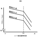
- FIG. 5 is a schematic diagram showing valve operation when the injection hole of the fuel injection valve according to the present invention is elliptical, and a schematic diagram viewed from the arrow c in the cc cross section. It is a figure showing the relationship between the flow velocity in a seat part and penetration.
- FIG. 1 is a cross-sectional view showing an example of a fuel injection valve according to the present invention.
- the electromagnetic fuel injection valve shown in FIG. 1 is an ON / OFF valve that controls the injection and stop of fuel by opening and closing the gap with the valve seat 101 when the valve body 102 moves up and down.
- the valve body 102 When the coil 103 is not energized, the valve body 102 is urged in the direction of the valve seat 101 by the urging spring 104, and the valve is in a closed state.
- a magnetic attractive force is generated between the magnetic core 113 and the movable element 106, and the movable element 106 is displaced together with the valve body 102 in the direction of the magnetic core 113 to open the valve.
- a gap is formed between the valve seat 101 and the valve body 102, and the fuel passes through this gap to reach the injection hole 107 and is injected from the injection hole 107.
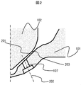
- FIG. 2 is a cross-sectional view of the injection nozzle in which the vicinity of the injection hole 107 of the fuel injection valve according to the present invention is enlarged.
- a part of the valve body 102 is formed as a spherical surface
- the valve seat 101 is formed as a conical surface.
- the valve body 102 comes into contact with the valve seat 101 at the seat portion 201.
- the seat portion 201 when the valve is open, the distance between the seat surface 203 and the surface of the valve body 102 is the smallest.
- valve open state In a state where the valve is open (valve open state), the flow passage area of the seat portion 201 is the smallest immediately upstream and immediately downstream. For this reason, the flow rate of the fuel in the seat portion 201 is maximized in the range immediately upstream and immediately downstream. This flow velocity is the seat portion flow velocity.
- the fuel After the fuel reaches a high speed in the seat portion 201, the fuel flows into the injection hole 107.
- the fuel that has flowed in has a flow velocity component (axial flow velocity) in the direction of the axis 202 of the injection hole inside the injection hole 107 and a flow velocity component (flow velocity in the spreading direction) perpendicular to the axis 202 of the injection hole. It is injected to the outside of 107.
- the fuel after being injected becomes a mist-like spray and travels while spreading.
- the penetration can be defined by the reach of the spray after a certain time. By measuring the penetration, it is possible to know whether the spray is easy to reach far or stay at a short distance.
- the spray penetration is strongly influenced by the initial velocity when fuel is ejected from the injection hole and the air resistance that the droplets receive after ejection.
- the initial velocity at the time of ejection is the main factor that determines penetration, and the axial flow velocity of the nozzle hole corresponds to this initial velocity. In order to shorten the penetration, this initial speed needs to be small.
- Air resistance is affected by spray spread.
- the distance between the droplets being sprayed increases, making it less susceptible to the effects of air flow formed by droplets in the vicinity of a droplet. Since the air flow formed by neighboring droplets is close to the velocity of a certain droplet itself, the more affected by the air flow formed by neighboring droplets, the smaller the relative velocity between the droplet and air, Therefore, the air resistance becomes small. Conversely, if the influence of the air flow formed by neighboring droplets is small, the air resistance tends to increase.
- the spray spreads and the distance between the droplets is large, the air resistance received by the droplets is likely to increase, and therefore the penetration is easily shortened.
- the spreading direction flow velocity in the injection hole may be increased.
- the flow velocity in the seat portion 201 is increased.
- the pressure loss in the seat portion 201 increases, and the injection amount (static flow) per unit time of the injection valve decreases as it is. Therefore, in order to obtain a predetermined static flow, the total cross-sectional area of the injection hole 107 is increased according to the design value of the flow velocity at the seat portion 201.
- the total cross-sectional area thereof should be designed to be large.
- the flow velocity (unit m / s) at the seat portion is a static flow Q (m 3 / s) where A (m 3 ) is the fuel passage area of the gap formed by the seat surface 203 and the surface of the valve body 102. ) Is divided by A.
- the seat surface 203 has a conical surface shape as in this embodiment and this surface and the surface of the valve body 102 are in contact with each other to open and close the valve, the apex angle ⁇ (°) of the conical surface is also provided.
- the flow of fuel becomes a decelerating flow from the seat portion 201 toward the nozzle hole 107. That is, the flow velocity in the nozzle hole 107 is smaller than the flow velocity in the seat portion 201.
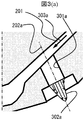
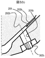
- the flow in the deceleration flow tends to be unstable. For this reason, the flow in the nozzle hole 107 tends to have many turbulence components due to the deceleration flow, and the flow velocity distribution in the nozzle holes is easily made uniform by the turbulence components. That is, as in the flow velocity distribution shown in FIG.
- FIG. 3A shows an example in which the flow velocity 303a in the seat portion 201 is slow.
- the flow velocity distribution 302a is as follows. In the vicinity of the nozzle hole inner wall 301a, the gradient is gentle, and the non-uniform flow velocity distribution is likely to have a large maximum flow velocity.
- the difference between the fast flow velocity and the slow flow velocity is small, and when the flow rate per unit time from the injection hole is constant, it is faster than when smoothing is not performed.
- the effect of reducing the portion that becomes the flow velocity or reducing the maximum value of the flow velocity can be obtained.
- a large flow velocity region and a large maximum flow velocity cause an increase in penetration. That is, the penetration can be shortened by obtaining a smooth flow velocity distribution that can reduce the fast flow velocity region and the maximum value of the flow velocity.
- the present invention by increasing the sheet portion flow velocity, the flow velocity distribution in the injection hole is smoothed, and the penetration is shortened.
- the flow velocity vector in the seat portion 201 is directed in a direction different from the nozzle hole axis direction.
- the increase in the flow velocity in the seat portion 201 has an effect of increasing the flow velocity of the direction component different from the direction of the injection hole shafts 202a and 202b, that is, the flow velocity component in the spreading direction at the inlet portion of the injection hole 107.
- the increase in the turbulence component at the nozzle hole 107 due to the above-described deceleration flow and the flow velocity of the spreading direction component at the outlet of the nozzle hole 107 cause a transition to a turbulent flow at the inlet portion of the nozzle hole 107. Is more conducive.
- the turbulence component in the nozzle hole 107 increases, the flow velocity distribution is smoothed, and the maximum flow velocity is reduced.
- the component of the flow velocity spreading direction increases due to the turbulent component at the nozzle hole outlet.
- the relationship between the flow velocity and the penetration in the seat portion 201 is as shown in FIG. 6, and a region where the penetration is rapidly shortened particularly in a region where the flow velocity is high appears.
- the horizontal axis is a value obtained by dividing the flow velocity in the seat portion 201 by the square root of the fuel pressure (seat portion flow velocity characteristic value), and the vertical axis is the penetration at a certain fuel pressure. As shown in FIG. 6, when the seat flow velocity characteristic value exceeds 28, the penetration can be rapidly reduced regardless of the fuel pressure.
- the cross-sectional area A is a denominator appearing in the equation (1) and can be expressed as the equation (2).
- A Ds ⁇ Y ⁇ ⁇ ⁇ Sin ( ⁇ / 2 ⁇ (2) That is, the flow velocity at the seat portion 201 can be increased by reducing the maximum lift amount Y of the valve body 102, reducing the seat diameter Ds, or reducing the seat angle ⁇ .
- applying an R shape 401 to the inlet portion of the injection hole 107 ′ as shown in FIG. 4 so as to reduce the pressure loss at the injection hole 107 is effective for obtaining a desired static flow.
- the R shape 401 at the inlet portion of the nozzle hole 107 ′ as shown in FIG. 4 suppresses the separation of the flow at the inlet of the nozzle hole 107 ′, and the effective sectional area of the nozzle hole is widened to reduce the pressure loss of the nozzle hole.
- a desired static flow can be obtained even if a higher flow velocity is set in the sheet portion 201.
- the effect of suppressing the separation of the flow at the inlet R of the nozzle hole 107 ′ increases the uniformity of the flow velocity in the nozzle hole 107 ′, and can reduce the maximum flow velocity, which is effective for shortening the penetration. Furthermore, by improving the flow rate uniformity in the nozzle hole 107 ′ by suppressing the separation of the flow, the amount of fuel discharged at a low flow rate is reduced, and the coarse particles formed by these low flow rate fuels are suppressed, and the atomization is reduced. The effect to improve is also acquired.
- the diameter of the nozzle hole 107 may be set large. Even when the diameter of the injection hole 107 is set to be large, pressure loss due to the injection hole 107 can be suppressed, and a desired static flow can be easily obtained even when the flow velocity at the seat portion 201 is increased.
- the total cross-sectional area of the plurality of injection holes 107 may be set larger than the fuel passage cross-sectional area A (formula (2)) in the seat portion 201. When such a fuel passage cross-sectional area is set, the flow from the seat portion 201 toward the nozzle hole 107 becomes a decelerating flow, which not only easily induces flow disturbance, but also the average flow velocity itself at the nozzle hole 107. Therefore, the penetration can be shortened.
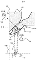
- the cross section of the injection hole 507 elliptical as shown in FIG.
- a non-circular injection hole 507 having a cross-sectional shape such as an ellipse
- a direction A perpendicular to the surface 501 at the point where the surface 501 where the injection hole 507 is drilled and the axis 502 of the injection hole intersect.
- the area of the injection hole inlet shape 503 when viewed from above is smaller than the area of the injection hole outlet shape 504 when the elliptical injection hole 507 is viewed from the axial direction b of the injection hole. It is good to set the cross-sectional shape.
- the inlet shape 503 when an elliptical nozzle hole is set is closer to a perfect circle than the outlet shape 504. That is, by the perforation of such an elliptical injection hole, it is possible to obtain an effect of increasing the cross-sectional area from the injection hole inlet to the injection hole outlet, and therefore the flow is decelerated toward the injection hole outlet inside the injection hole. The effect can be obtained. As a result, the flow velocity at the nozzle hole outlet is suppressed, and penetration can be suppressed.
- the major axis and the minor axis are set in the axial direction when the major axis of the ellipse is projected onto a plane perpendicular to the axis 508 of the valve body.
- the major axis 506 may be shifted from the axial center 508 of the valve body. (In FIG. 5, the projected major axis 506 is displaced from the axis 508 of the valve element.
- the segment a connecting the nozzle hole center o and the valve element axis 508 on the projection surface and the major axis 506 In this way, by making the cross section of the injection hole 507 elliptical and increasing the cross sectional area only in a specific direction, even if the flow velocity at the sheet portion 201 is high, the desired amount of deviation ⁇ is 90 °. A flow rate can be obtained. Further, by setting the projected major axis offset from the axial center 508 of the valve body, the direction of the longest portion of the cross-sectional shape of the injection hole 507 coincides with the inflow direction from the seat portion 201. You can avoid doing it.
- penetration can be shortened by increasing the flow velocity in the seat portion 201, and desired rectification can be obtained by selecting an appropriate nozzle hole shape.
Landscapes
- Engineering & Computer Science (AREA)
- Chemical & Material Sciences (AREA)
- Combustion & Propulsion (AREA)
- Mechanical Engineering (AREA)
- General Engineering & Computer Science (AREA)
- Physics & Mathematics (AREA)
- Electromagnetism (AREA)
- Fuel-Injection Apparatus (AREA)
Abstract
Description
前記弁体と前記弁座が形成する前記隙間における燃料の流速が、前記燃料に印加された圧力の平方根に28を乗じた値よりも大きくなるように設定した。
v=Q/{Ds・Y・π・Sin(θ/2}) ・・・(1)
この関係は、シート面が本実施例のような円錐面でない場合には、弁体102の接触部と接する面と、噴射弁の軸が為す角度の二倍をθとして用いて計算することもできる。また、弁体102とシート面203との接触部の円が複数ある場合や、円が幅を持っている場合には、最も小さい円の値を用いることで、シート部に生じる流速の最も大きい値を評価できるようになる。
A=Ds・Y・π・Sin(θ/2} ・・・(2)
すなわち、弁体102の最大リフト量Yを小さくしたり、シート径Dsを小さくしたり、シート角θを小さくすることによって、シート部201での流速を高めることができる。
102…弁体
103…ガイド部材
104…筒状部材
105…ガイド部材
106…可動子
108…磁気コア
109…コイル
110…付勢ばね
111…コネクタ
112…燃料入口
201…シート部
202、202a、202b…噴射孔の軸
203…シート面
301a、301b…噴射孔内壁
302a、302b…流速分布
303a、303b…シート部流速
401…入口部R
501…シート面
502…噴射孔の軸
503…噴射孔の入口形状
504…噴射孔の出口形状
506…長径軸
507…噴射孔
508…弁体の軸芯
Claims (5)
- 弁体との間で隙間を形成する弁座を備え、前記隙間を燃料が通過し、前記隙間よりも下流に複数個の噴射孔を備え、圧力が印加された燃料が該噴射孔から流出する燃料噴射弁において、
前記弁体と前記弁座が形成する前記隙間における燃料の流速が、前記燃料に印加された圧力の平方根に28を乗じた値よりも大きくなるように設定されたことを特徴とする燃料噴射弁。 - 請求項1に記載の燃料噴射弁であって、前記噴射孔の入口にR形状を設け、前記隙間における燃料の流速を高めたことを特徴とする燃料噴射弁。
- 請求項1乃至2に記載の燃料噴射弁であって、前記噴射孔の総断断面積は前記隙間における流路断面積よりも大きいことを特徴とする燃料噴射弁。
- 請求項1乃至3に記載の燃料噴射弁であって、前記噴射孔の断面形状が楕円状に穿孔されたことを特徴とする燃料噴射弁。
- 請求項4に記載の燃料噴射弁であって、前記噴射孔の軸と前記噴射孔が穿孔されている面とが交わる位置において、該面と垂直な方向から前記噴射孔を見た時の前記噴射孔の入口形状が為す面積よりも、前記噴射孔の出口の形状を噴射孔の軸の方向から見た時の断面積の方が大きくなるように設定されたことを特徴とする燃料噴射弁。
Priority Applications (3)
| Application Number | Priority Date | Filing Date | Title |
|---|---|---|---|
| DE112014000332.8T DE112014000332T5 (de) | 2013-02-04 | 2014-01-24 | Kraftstoffeinspritzventil |
| CN201480006220.3A CN104956067B (zh) | 2013-02-04 | 2014-01-24 | 燃料喷射阀 |
| US14/765,438 US9617963B2 (en) | 2013-02-04 | 2014-01-24 | Fuel injection valve |
Applications Claiming Priority (2)
| Application Number | Priority Date | Filing Date | Title |
|---|---|---|---|
| JP2013019061A JP6036354B2 (ja) | 2013-02-04 | 2013-02-04 | 燃料噴射弁 |
| JP2013-019061 | 2013-02-04 |
Publications (1)
| Publication Number | Publication Date |
|---|---|
| WO2014119472A1 true WO2014119472A1 (ja) | 2014-08-07 |
Family
ID=51262186
Family Applications (1)
| Application Number | Title | Priority Date | Filing Date |
|---|---|---|---|
| PCT/JP2014/051438 Ceased WO2014119472A1 (ja) | 2013-02-04 | 2014-01-24 | 燃料噴射弁 |
Country Status (5)
| Country | Link |
|---|---|
| US (1) | US9617963B2 (ja) |
| JP (1) | JP6036354B2 (ja) |
| CN (1) | CN104956067B (ja) |
| DE (1) | DE112014000332T5 (ja) |
| WO (1) | WO2014119472A1 (ja) |
Cited By (1)
| Publication number | Priority date | Publication date | Assignee | Title |
|---|---|---|---|---|
| WO2018042910A1 (ja) * | 2016-08-31 | 2018-03-08 | 日立オートモティブシステムズ株式会社 | 燃料噴射装置 |
Families Citing this family (9)
| Publication number | Priority date | Publication date | Assignee | Title |
|---|---|---|---|---|
| JP6264221B2 (ja) * | 2014-07-24 | 2018-01-24 | 株式会社デンソー | 燃料噴射ノズル |
| JP2016089660A (ja) * | 2014-10-31 | 2016-05-23 | 日立オートモティブシステムズ株式会社 | 燃料噴射装置 |
| JP6023151B2 (ja) | 2014-11-07 | 2016-11-09 | トヨタ自動車株式会社 | 燃料噴射弁 |
| WO2018207582A1 (ja) * | 2017-05-12 | 2018-11-15 | 日立オートモティブシステムズ株式会社 | 燃料噴射弁 |
| JP7124351B2 (ja) * | 2018-03-08 | 2022-08-24 | 株式会社デンソー | 燃料噴射弁および燃料噴射システム |
| WO2020085039A1 (ja) * | 2018-10-26 | 2020-04-30 | 日立オートモティブシステムズ株式会社 | 燃料噴射弁 |
| JP7167663B2 (ja) * | 2018-11-28 | 2022-11-09 | 株式会社デンソー | 燃料噴射弁 |
| JP7272645B2 (ja) * | 2019-06-20 | 2023-05-12 | 株式会社デンソー | 燃料噴射弁 |
| GB2593892B (en) * | 2020-04-06 | 2022-08-03 | Delphi Automotive Systems Lux | Fuel Injector |
Citations (6)
| Publication number | Priority date | Publication date | Assignee | Title |
|---|---|---|---|---|
| JPS5922984U (ja) * | 1982-08-04 | 1984-02-13 | 日産自動車株式会社 | 燃料噴射ノズル |
| JP2001182641A (ja) * | 1999-12-24 | 2001-07-06 | Denso Corp | 燃料噴射ノズルおよびその製造方法 |
| JP2003184706A (ja) * | 2001-11-15 | 2003-07-03 | Robert Bosch Gmbh | 燃料噴射弁 |
| JP2008121578A (ja) * | 2006-11-13 | 2008-05-29 | Toyota Motor Corp | 燃料噴射弁 |
| JP2009513856A (ja) * | 2003-06-30 | 2009-04-02 | ダイムラー・アクチェンゲゼルシャフト | 圧縮点火内燃機関 |
| JP2011001864A (ja) * | 2009-06-18 | 2011-01-06 | Hitachi Automotive Systems Ltd | 燃料噴射弁 |
Family Cites Families (9)
| Publication number | Priority date | Publication date | Assignee | Title |
|---|---|---|---|---|
| US4540126A (en) | 1982-04-08 | 1985-09-10 | Nissan Motor Co., Ltd. | Fuel injection nozzle |
| US4971254A (en) * | 1989-11-28 | 1990-11-20 | Siemens-Bendix Automotive Electronics L.P. | Thin orifice swirl injector nozzle |
| JP3662775B2 (ja) | 1999-06-04 | 2005-06-22 | 株式会社日立製作所 | 筒内噴射式エンジン、それに用いるアトマイザ、及び燃料噴射弁 |
| US6499467B1 (en) * | 2000-03-31 | 2002-12-31 | Cummins Inc. | Closed nozzle fuel injector with improved controllabilty |
| JP2010038126A (ja) * | 2008-08-08 | 2010-02-18 | Hitachi Ltd | 燃料噴射弁 |
| JP2010053796A (ja) * | 2008-08-29 | 2010-03-11 | Hitachi Ltd | 燃料噴射弁 |
| US8827187B2 (en) * | 2010-07-01 | 2014-09-09 | Toyota Jidosha Kabushiki Kaisha | Fuel injection valve and internal combustion engine |
| JP2012036865A (ja) * | 2010-08-10 | 2012-02-23 | Toyota Motor Corp | 噴射ノズル |
| JP5358621B2 (ja) * | 2011-06-20 | 2013-12-04 | 日立オートモティブシステムズ株式会社 | 燃料噴射装置 |
-
2013
- 2013-02-04 JP JP2013019061A patent/JP6036354B2/ja not_active Expired - Fee Related
-
2014
- 2014-01-24 CN CN201480006220.3A patent/CN104956067B/zh not_active Expired - Fee Related
- 2014-01-24 US US14/765,438 patent/US9617963B2/en not_active Expired - Fee Related
- 2014-01-24 DE DE112014000332.8T patent/DE112014000332T5/de active Pending
- 2014-01-24 WO PCT/JP2014/051438 patent/WO2014119472A1/ja not_active Ceased
Patent Citations (6)
| Publication number | Priority date | Publication date | Assignee | Title |
|---|---|---|---|---|
| JPS5922984U (ja) * | 1982-08-04 | 1984-02-13 | 日産自動車株式会社 | 燃料噴射ノズル |
| JP2001182641A (ja) * | 1999-12-24 | 2001-07-06 | Denso Corp | 燃料噴射ノズルおよびその製造方法 |
| JP2003184706A (ja) * | 2001-11-15 | 2003-07-03 | Robert Bosch Gmbh | 燃料噴射弁 |
| JP2009513856A (ja) * | 2003-06-30 | 2009-04-02 | ダイムラー・アクチェンゲゼルシャフト | 圧縮点火内燃機関 |
| JP2008121578A (ja) * | 2006-11-13 | 2008-05-29 | Toyota Motor Corp | 燃料噴射弁 |
| JP2011001864A (ja) * | 2009-06-18 | 2011-01-06 | Hitachi Automotive Systems Ltd | 燃料噴射弁 |
Cited By (2)
| Publication number | Priority date | Publication date | Assignee | Title |
|---|---|---|---|---|
| WO2018042910A1 (ja) * | 2016-08-31 | 2018-03-08 | 日立オートモティブシステムズ株式会社 | 燃料噴射装置 |
| JPWO2018042910A1 (ja) * | 2016-08-31 | 2019-03-14 | 日立オートモティブシステムズ株式会社 | 燃料噴射装置 |
Also Published As
| Publication number | Publication date |
|---|---|
| US20150377200A1 (en) | 2015-12-31 |
| DE112014000332T5 (de) | 2015-09-24 |
| CN104956067A (zh) | 2015-09-30 |
| JP2014148955A (ja) | 2014-08-21 |
| CN104956067B (zh) | 2017-09-08 |
| JP6036354B2 (ja) | 2016-11-30 |
| US9617963B2 (en) | 2017-04-11 |
Similar Documents
| Publication | Publication Date | Title |
|---|---|---|
| JP6036354B2 (ja) | 燃料噴射弁 | |
| US9739247B2 (en) | Mist forming method using fluid injection valve, fluid injection valve, and mist forming apparatus | |
| JP5115654B2 (ja) | 燃料噴射弁及び内燃機関 | |
| JP5933720B2 (ja) | 燃料噴射弁 | |
| JP6186130B2 (ja) | 燃料噴射弁及び燃料噴射弁の製造方法 | |
| JP4072402B2 (ja) | 燃料噴射弁およびそれを搭載した内燃機関 | |
| JP2008280981A (ja) | 燃料噴射装置およびそれを搭載した内燃機関 | |
| CN102606329A (zh) | 内燃机的控制装置及内燃机 | |
| US10280885B2 (en) | Fluid injection valve and spray generator | |
| JP2013002433A (ja) | 流体噴射弁による噴霧生成方法、流体噴射弁及び噴霧生成装置 | |
| CN206190444U (zh) | 喷嘴头及流体喷射阀 | |
| JP6862284B2 (ja) | 燃料噴射弁及びエンジンシステム | |
| JP5774108B2 (ja) | 燃料噴射弁 | |
| JP2012145048A (ja) | 燃料噴射弁 | |
| JP2013249826A (ja) | 燃料噴射弁、及び内燃機関の燃料噴射装置 | |
| JP5627743B1 (ja) | 流体噴射弁及び噴霧生成装置 | |
| JP7187341B2 (ja) | 燃料噴射装置および制御装置 | |
| JP4224666B2 (ja) | 燃料噴射ノズルおよびその加工方法 | |
| JP5627742B1 (ja) | 流体噴射弁及び噴霧生成装置 | |
| JP5983535B2 (ja) | 燃料噴射弁 | |
| JP6838216B2 (ja) | 燃料噴射弁 | |
| CN107532557B (zh) | 燃料喷射装置 | |
| JP5766317B1 (ja) | 燃料噴射弁 | |
| JP5478671B2 (ja) | 流体噴射弁による噴霧生成方法、流体噴射弁及び噴霧生成装置 | |
| JP6012693B2 (ja) | 流体噴射弁およびこれを備えた噴霧生成装置 |
Legal Events
| Date | Code | Title | Description |
|---|---|---|---|
| 121 | Ep: the epo has been informed by wipo that ep was designated in this application |
Ref document number: 14745431 Country of ref document: EP Kind code of ref document: A1 |
|
| WWE | Wipo information: entry into national phase |
Ref document number: 1120140003328 Country of ref document: DE Ref document number: 112014000332 Country of ref document: DE |
|
| WWE | Wipo information: entry into national phase |
Ref document number: 14765438 Country of ref document: US |
|
| 122 | Ep: pct application non-entry in european phase |
Ref document number: 14745431 Country of ref document: EP Kind code of ref document: A1 |