WO2014119038A1 - 分光測定装置、分光測定方法、及び試料容器 - Google Patents
分光測定装置、分光測定方法、及び試料容器 Download PDFInfo
- Publication number
- WO2014119038A1 WO2014119038A1 PCT/JP2013/075033 JP2013075033W WO2014119038A1 WO 2014119038 A1 WO2014119038 A1 WO 2014119038A1 JP 2013075033 W JP2013075033 W JP 2013075033W WO 2014119038 A1 WO2014119038 A1 WO 2014119038A1
- Authority
- WO
- WIPO (PCT)
- Prior art keywords
- sample
- excitation light
- light
- opening
- measured
- Prior art date
Links
- 238000001228 spectrum Methods 0.000 title abstract description 15
- 238000000034 method Methods 0.000 title description 4
- 230000005284 excitation Effects 0.000 claims abstract description 129
- 230000003287 optical effect Effects 0.000 claims abstract description 53
- 238000006862 quantum yield reaction Methods 0.000 claims abstract description 31
- 238000001514 detection method Methods 0.000 claims abstract description 5
- 238000005259 measurement Methods 0.000 claims description 50
- 238000003860 storage Methods 0.000 claims description 10
- 238000000691 measurement method Methods 0.000 claims description 9
- 230000001678 irradiating effect Effects 0.000 claims description 7
- 238000010521 absorption reaction Methods 0.000 description 15
- 238000007405 data analysis Methods 0.000 description 10
- 230000004308 accommodation Effects 0.000 description 8
- 238000004611 spectroscopical analysis Methods 0.000 description 8
- 239000000463 material Substances 0.000 description 7
- 230000003595 spectral effect Effects 0.000 description 7
- 238000012937 correction Methods 0.000 description 6
- 230000031700 light absorption Effects 0.000 description 6
- 238000004458 analytical method Methods 0.000 description 5
- 230000000694 effects Effects 0.000 description 5
- 238000010586 diagram Methods 0.000 description 4
- 230000004048 modification Effects 0.000 description 4
- 238000012986 modification Methods 0.000 description 4
- OAICVXFJPJFONN-UHFFFAOYSA-N Phosphorus Chemical compound [P] OAICVXFJPJFONN-UHFFFAOYSA-N 0.000 description 3
- 238000004364 calculation method Methods 0.000 description 3
- 230000007480 spreading Effects 0.000 description 3
- 238000003892 spreading Methods 0.000 description 3
- 238000011144 upstream manufacturing Methods 0.000 description 3
- TZCXTZWJZNENPQ-UHFFFAOYSA-L barium sulfate Chemical compound [Ba+2].[O-]S([O-])(=O)=O TZCXTZWJZNENPQ-UHFFFAOYSA-L 0.000 description 2
- 230000008859 change Effects 0.000 description 2
- 238000009826 distribution Methods 0.000 description 2
- 239000000835 fiber Substances 0.000 description 2
- 229910052751 metal Inorganic materials 0.000 description 2
- 239000002184 metal Substances 0.000 description 2
- 238000005424 photoluminescence Methods 0.000 description 2
- 239000010453 quartz Substances 0.000 description 2
- 230000005855 radiation Effects 0.000 description 2
- VYPSYNLAJGMNEJ-UHFFFAOYSA-N silicon dioxide Inorganic materials O=[Si]=O VYPSYNLAJGMNEJ-UHFFFAOYSA-N 0.000 description 2
- 229910052724 xenon Inorganic materials 0.000 description 2
- FHNFHKCVQCLJFQ-UHFFFAOYSA-N xenon atom Chemical compound [Xe] FHNFHKCVQCLJFQ-UHFFFAOYSA-N 0.000 description 2
- 229920000995 Spectralon Polymers 0.000 description 1
- 230000004323 axial length Effects 0.000 description 1
- 229920000547 conjugated polymer Polymers 0.000 description 1
- 230000007423 decrease Effects 0.000 description 1
- 238000005401 electroluminescence Methods 0.000 description 1
- 238000005516 engineering process Methods 0.000 description 1
- 230000001747 exhibiting effect Effects 0.000 description 1
- 238000009434 installation Methods 0.000 description 1
- 239000007788 liquid Substances 0.000 description 1
- 238000004519 manufacturing process Methods 0.000 description 1
- 239000013307 optical fiber Substances 0.000 description 1
- 230000002093 peripheral effect Effects 0.000 description 1
- 230000035699 permeability Effects 0.000 description 1
- 229920001343 polytetrafluoroethylene Polymers 0.000 description 1
- 239000004810 polytetrafluoroethylene Substances 0.000 description 1
- 239000000843 powder Substances 0.000 description 1
- 238000012545 processing Methods 0.000 description 1
- 230000004044 response Effects 0.000 description 1
- 230000035945 sensitivity Effects 0.000 description 1
- 239000007787 solid Substances 0.000 description 1
- 239000000126 substance Substances 0.000 description 1
- 239000010409 thin film Substances 0.000 description 1
- 238000002834 transmittance Methods 0.000 description 1
- 239000012780 transparent material Substances 0.000 description 1
Images


Classifications
-
- G—PHYSICS
- G01—MEASURING; TESTING
- G01N—INVESTIGATING OR ANALYSING MATERIALS BY DETERMINING THEIR CHEMICAL OR PHYSICAL PROPERTIES
- G01N21/00—Investigating or analysing materials by the use of optical means, i.e. using sub-millimetre waves, infrared, visible or ultraviolet light
- G01N21/62—Systems in which the material investigated is excited whereby it emits light or causes a change in wavelength of the incident light
- G01N21/63—Systems in which the material investigated is excited whereby it emits light or causes a change in wavelength of the incident light optically excited
- G01N21/64—Fluorescence; Phosphorescence
- G01N21/645—Specially adapted constructive features of fluorimeters
-
- G—PHYSICS
- G01—MEASURING; TESTING
- G01J—MEASUREMENT OF INTENSITY, VELOCITY, SPECTRAL CONTENT, POLARISATION, PHASE OR PULSE CHARACTERISTICS OF INFRARED, VISIBLE OR ULTRAVIOLET LIGHT; COLORIMETRY; RADIATION PYROMETRY
- G01J3/00—Spectrometry; Spectrophotometry; Monochromators; Measuring colours
- G01J3/02—Details
- G01J3/0205—Optical elements not provided otherwise, e.g. optical manifolds, diffusers, windows
- G01J3/021—Optical elements not provided otherwise, e.g. optical manifolds, diffusers, windows using plane or convex mirrors, parallel phase plates, or particular reflectors
-
- G—PHYSICS
- G01—MEASURING; TESTING
- G01J—MEASUREMENT OF INTENSITY, VELOCITY, SPECTRAL CONTENT, POLARISATION, PHASE OR PULSE CHARACTERISTICS OF INFRARED, VISIBLE OR ULTRAVIOLET LIGHT; COLORIMETRY; RADIATION PYROMETRY
- G01J3/00—Spectrometry; Spectrophotometry; Monochromators; Measuring colours
- G01J3/02—Details
- G01J3/0205—Optical elements not provided otherwise, e.g. optical manifolds, diffusers, windows
- G01J3/0254—Spectrometers, other than colorimeters, making use of an integrating sphere
-
- G—PHYSICS
- G01—MEASURING; TESTING
- G01J—MEASUREMENT OF INTENSITY, VELOCITY, SPECTRAL CONTENT, POLARISATION, PHASE OR PULSE CHARACTERISTICS OF INFRARED, VISIBLE OR ULTRAVIOLET LIGHT; COLORIMETRY; RADIATION PYROMETRY
- G01J3/00—Spectrometry; Spectrophotometry; Monochromators; Measuring colours
- G01J3/02—Details
- G01J3/0291—Housings; Spectrometer accessories; Spatial arrangement of elements, e.g. folded path arrangements
-
- G—PHYSICS
- G01—MEASURING; TESTING
- G01J—MEASUREMENT OF INTENSITY, VELOCITY, SPECTRAL CONTENT, POLARISATION, PHASE OR PULSE CHARACTERISTICS OF INFRARED, VISIBLE OR ULTRAVIOLET LIGHT; COLORIMETRY; RADIATION PYROMETRY
- G01J3/00—Spectrometry; Spectrophotometry; Monochromators; Measuring colours
- G01J3/28—Investigating the spectrum
- G01J3/44—Raman spectrometry; Scattering spectrometry ; Fluorescence spectrometry
- G01J3/4406—Fluorescence spectrometry
-
- G—PHYSICS
- G01—MEASURING; TESTING
- G01J—MEASUREMENT OF INTENSITY, VELOCITY, SPECTRAL CONTENT, POLARISATION, PHASE OR PULSE CHARACTERISTICS OF INFRARED, VISIBLE OR ULTRAVIOLET LIGHT; COLORIMETRY; RADIATION PYROMETRY
- G01J3/00—Spectrometry; Spectrophotometry; Monochromators; Measuring colours
- G01J3/28—Investigating the spectrum
- G01J3/443—Emission spectrometry
-
- G—PHYSICS
- G01—MEASURING; TESTING
- G01N—INVESTIGATING OR ANALYSING MATERIALS BY DETERMINING THEIR CHEMICAL OR PHYSICAL PROPERTIES
- G01N21/00—Investigating or analysing materials by the use of optical means, i.e. using sub-millimetre waves, infrared, visible or ultraviolet light
- G01N21/01—Arrangements or apparatus for facilitating the optical investigation
-
- G—PHYSICS
- G01—MEASURING; TESTING
- G01N—INVESTIGATING OR ANALYSING MATERIALS BY DETERMINING THEIR CHEMICAL OR PHYSICAL PROPERTIES
- G01N21/00—Investigating or analysing materials by the use of optical means, i.e. using sub-millimetre waves, infrared, visible or ultraviolet light
- G01N21/62—Systems in which the material investigated is excited whereby it emits light or causes a change in wavelength of the incident light
- G01N21/63—Systems in which the material investigated is excited whereby it emits light or causes a change in wavelength of the incident light optically excited
- G01N21/64—Fluorescence; Phosphorescence
- G01N21/645—Specially adapted constructive features of fluorimeters
- G01N2021/6463—Optics
- G01N2021/6469—Cavity, e.g. ellipsoid
-
- G—PHYSICS
- G01—MEASURING; TESTING
- G01N—INVESTIGATING OR ANALYSING MATERIALS BY DETERMINING THEIR CHEMICAL OR PHYSICAL PROPERTIES
- G01N21/00—Investigating or analysing materials by the use of optical means, i.e. using sub-millimetre waves, infrared, visible or ultraviolet light
- G01N21/62—Systems in which the material investigated is excited whereby it emits light or causes a change in wavelength of the incident light
- G01N21/63—Systems in which the material investigated is excited whereby it emits light or causes a change in wavelength of the incident light optically excited
- G01N21/64—Fluorescence; Phosphorescence
- G01N21/645—Specially adapted constructive features of fluorimeters
- G01N2021/6482—Sample cells, cuvettes
-
- G—PHYSICS
- G01—MEASURING; TESTING
- G01N—INVESTIGATING OR ANALYSING MATERIALS BY DETERMINING THEIR CHEMICAL OR PHYSICAL PROPERTIES
- G01N21/00—Investigating or analysing materials by the use of optical means, i.e. using sub-millimetre waves, infrared, visible or ultraviolet light
- G01N21/62—Systems in which the material investigated is excited whereby it emits light or causes a change in wavelength of the incident light
- G01N21/63—Systems in which the material investigated is excited whereby it emits light or causes a change in wavelength of the incident light optically excited
- G01N21/64—Fluorescence; Phosphorescence
- G01N21/645—Specially adapted constructive features of fluorimeters
- G01N2021/6484—Optical fibres
-
- G—PHYSICS
- G01—MEASURING; TESTING
- G01N—INVESTIGATING OR ANALYSING MATERIALS BY DETERMINING THEIR CHEMICAL OR PHYSICAL PROPERTIES
- G01N21/00—Investigating or analysing materials by the use of optical means, i.e. using sub-millimetre waves, infrared, visible or ultraviolet light
- G01N21/62—Systems in which the material investigated is excited whereby it emits light or causes a change in wavelength of the incident light
- G01N21/63—Systems in which the material investigated is excited whereby it emits light or causes a change in wavelength of the incident light optically excited
- G01N21/64—Fluorescence; Phosphorescence
- G01N21/6489—Photoluminescence of semiconductors
-
- G—PHYSICS
- G01—MEASURING; TESTING
- G01N—INVESTIGATING OR ANALYSING MATERIALS BY DETERMINING THEIR CHEMICAL OR PHYSICAL PROPERTIES
- G01N2201/00—Features of devices classified in G01N21/00
- G01N2201/06—Illumination; Optics
- G01N2201/065—Integrating spheres
Definitions
- the present invention relates to a spectroscopic measurement apparatus, a spectroscopic measurement method, and a sample container.
- Patent Document 1 describes a quantum efficiency measurement device. Yes.
- the quantum efficiency measuring device described in Patent Document 1 the reflection component in the phosphor of single wavelength radiation and the total emission component of the excited fluorescence emission are integrated by an integrating sphere, and the spectral energy distribution is measured.
- the total reflection component in the spectral reflectance standard of single wavelength radiation is integrated by an integrating sphere, and the spectral distribution is measured. Based on the measured value, the amount of photon absorbed by the phosphor and the amount of photon emitted from the fluorescent light are calculated, and the quantum yield of the phosphor is calculated from the ratio thereof.
- Patent Document 2 when obtaining the quantum yield, the sample is fixed at a position where the excitation light does not directly hit in the integrating sphere, and the intensity obtained by injecting the excitation light indirectly to the sample, There is described an absolute fluorescence quantum efficiency measuring device for obtaining the absorption rate of a sample from the intensity obtained by direct incidence of excitation light on the sample.
- Non-Patent Documents 1 to 3 describe that the quantum yield is calculated on the assumption that excitation light is incident on a part of the sample.
- the quantum yield is represented by the ratio of the number of photons of the excitation light absorbed by the sample to the number of photons of the light to be measured. Therefore, when the light to be measured is absorbed by self-absorption, the quantum yield to be calculated is calculated. There is a possibility that the rate is estimated to be smaller than the true value.
- an object of one aspect of the present invention is to provide a spectroscopic measurement apparatus, a spectroscopic measurement method, and a sample container that can accurately determine the quantum yield.
- a spectroscopic measurement device is a spectroscopic measurement device that detects excitation light by irradiating a sample to be measured with excitation light, and a light source that generates the excitation light.
- an integrator having an incident opening through which excitation light is incident and an output opening through which light to be measured is emitted, an accommodation unit disposed in the integrator for accommodating the sample, and the excitation light being incident on the sample
- An incident optical system a photodetector for detecting the light to be measured emitted from the exit aperture, and an analysis means for calculating the quantum yield of the sample based on the detection value detected by the photodetector, The excitation light is irradiated on the sample so as to enclose the sample.
- the self-absorption amount can be reduced, and the quantum yield can be obtained with high accuracy. This is due to the following reason. That is, when a part of the sample is irradiated with excitation light, the amount of self-absorption is large due to the large boundary area between the irradiated region and the non-irradiated region in the sample. This is because in the spectroscopic measurement apparatus, since the excitation light is irradiated so as to include the sample, the boundary area between the irradiated region and the non-irradiated region in the sample is narrowed, and the self-absorption amount is reduced.
- the incident optical system adjusts the excitation light so that the excitation light encloses the sample
- the structure in which the accommodating part accommodates a sample is mentioned so that excitation light may include a sample.
- the integrator has a sample introduction opening to which a sample holder for placing the accommodation unit in the integrator is attached, and the sample holder has an opening surface of the accommodation unit with respect to a plane orthogonal to the irradiation optical axis in the excitation light. May be attached to the sample introduction opening so as to be inclined. In this case, the reflected light of the excitation light can be prevented from returning directly to the incident aperture.
- the incident optical system may include an optical member having an opening having a shape having a major axis, and the major axis direction of the opening of the optical member and the inclination direction of the opening surface of the housing portion may have an angle. In these cases, the irradiation shape of the excitation light becomes more vertically long, and the accommodating portion can be surely included.
- the sample holder has a mounting surface for mounting the sample container including the accommodating portion, and the sample introduction opening is arranged so that the mounting surface is inclined with respect to a plane orthogonal to the irradiation optical axis in the excitation light. May be attached.
- the sample holder may include an inclined member having a placement surface.
- the incident optical system may include an optical member that adjusts the angle of the irradiation optical axis with respect to the opening surface of the housing portion.
- a spectroscopic measurement method is a spectroscopic measurement method of irradiating a sample to be measured with excitation light and detecting light to be measured, the step of arranging the sample in an integrator, Based on the detected light to be measured, the step of irradiating the sample with the excitation light so that the excitation light encloses the sample and making it incident on the sample, the step of detecting the light to be measured emitted from the integrator, and the detected light to be measured And a step of calculating a quantum yield of the sample.
- a sample container is a sample container used for quantum yield measurement using an integrator, a rectangular plate-shaped plate portion, and a convex portion provided on the plate portion, And a storage unit that stores the sample to be measured, and the storage unit stores the sample so that the excitation light applied to the sample includes the sample.
- the cross section of the convex portion may be circular, and the opening of the accommodating portion may be a shape having a long axis.
- the sample container is formed by fixing a cylindrical member having a through hole on the surface of the plate-like member, the plate portion being constituted by the plate-like member, and the convex portion being the cylindrical member. In this case, the sample container can be manufactured relatively easily.
- the quantum yield can be obtained with high accuracy.
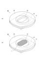
- FIG. 1 is a perspective view explaining accommodation of the sample in a storage container
- (b) is a perspective view which shows the continuation of Fig.7
- (a) is a graph which shows an example of the wavelength spectrum detected by reference measurement
- (b) is a graph which shows an example of the wavelength spectrum detected by sample measurement.
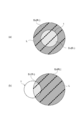
- (A) is a schematic diagram showing an example of the relationship between the irradiation area of the excitation light and the irradiated area of the sample
- (b) is a schematic diagram showing another example of the relationship between the irradiation area of the excitation light and the irradiated area of the sample.
- FIG. It is sectional drawing which shows the spectrometer which concerns on a modification.
- FIG. 1 is a diagram schematically illustrating a configuration of a spectrometer according to an embodiment.
- the spectroscopic measurement apparatus 100A measures or evaluates light emission characteristics such as fluorescence characteristics of a sample 1 as a sample to be measured by a photoluminescence method (PL method).
- Sample 1 is, for example, an organic EL (Electroluminescence) material or a white LED (Light Emitting) It is a fluorescent sample such as a light emitting material for a diode or FPD (Flat Panel Display).
- a powder, liquid (solution), solid or thin film can be used.
- the spectroscopic measurement apparatus 100A irradiates the sample 1 with excitation light having a predetermined wavelength, and detects the light to be measured generated in response to the irradiation.
- the spectroscopic measurement apparatus 100A includes an excitation light supply unit 10, an integrating sphere (integrator) 20, a spectroscopic analysis apparatus 30, and a data analysis apparatus 50.
- the excitation light supply unit 10 is for irradiating the sample 1 with excitation light for measuring light emission characteristics.
- the excitation light supply unit 10 includes at least an excitation light source (light source) 11, an incident light guide 12, and an optical filter 13.
- the excitation light source 11 generates excitation light, and is composed of, for example, a xenon lamp or a spectroscope.
- the incident light guide 12 guides the excitation light generated by the excitation light source 11 to the integrating sphere 20.
- an optical fiber can be used as the incident light guide 12, for example.
- the optical filter 13 selects a predetermined wavelength component from the light from the excitation light source 11, and emits excitation light of the predetermined wavelength component.
- an interference filter or the like is used as the optical filter 13, a predetermined wavelength component.
- the integrating sphere 20 introduces the sample 1 into the integrating sphere 20, an incident opening 21 for entering the excitation light into the integrating sphere 20, an exit opening 22 for emitting the measured light to the outside. And a sample introduction opening 23 for the purpose.
- a sample container holder (sample holder) 24 is attached (fixed) to the sample introduction opening 23, and a sample container 40 for storing the sample 1 is placed on the sample container holder 24 in the integrating sphere 20. Being held.
- the exit end of the incident light guide 12 is fixed to the incident opening 21, and the optical filter 13 is installed on the front side in the irradiation direction of the excitation light with respect to the incident light guide 12.
- an incident end of an output light guide 25 that guides light to be measured to the subsequent spectroscopic analyzer 30 is fixed to the output opening 22.
- the emission light guide 25 for example, a single fiber or a bundle fiber can be used.
- the spectroscopic analyzer 30 separates the light to be measured emitted from the exit opening 22 of the integrating sphere 20 and guided by the exit light guide 25, and acquires the wavelength spectrum thereof.
- the spectroscopic analysis device 30 here is configured as a multi-channel spectroscope having a spectroscopic unit 31 and a spectroscopic data generation unit 32.
- the spectroscopic unit 31 includes a spectroscope 31a for decomposing measured light into wavelength components, and a photodetector 31b for detecting the measured light decomposed by the spectroscope 31a.
- a photodetector 31b for example, a CCD linear sensor in which pixels of a plurality of channels (for example, 1024 channels) for detecting each wavelength component of the light to be measured are arranged one-dimensionally can be used.
- the wavelength region measured by the spectroscopic unit 31 can be set as appropriate according to the specific configuration, application, and the like.
- the spectral data generation unit 32 performs necessary signal processing on the detection signal output from each channel of the photodetector 31b, and generates wavelength spectrum data that is spectral data of the light to be measured.
- the wavelength spectrum data generated by the spectral data generation unit 32 is output to the data analysis device 50 at the subsequent stage.
- the data analyzer 50 is an analysis unit that performs necessary data analysis on the wavelength spectrum generated by the spectroscopic analyzer 30 and acquires information about the sample 1.
- the data analysis device 50 here calculates the quantum yield of the sample 1 based on the output from the spectroscopic analysis device 30 (details will be described later).
- the data analysis device 50 includes an input device 61 used for inputting an instruction for data analysis or the like, or inputting an analysis condition, and a display device 62 used for displaying the obtained data analysis result. It is connected.
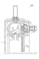
- FIG. 2 is a cross-sectional view showing an example of an integrating sphere in the spectroscopic measurement apparatus of FIG.
- the integrating sphere 20 is attached to a gantry (not shown) by, for example, an attaching screw or the like, and a highly diffuse reflective material is applied to the inner wall thereof.
- the integrating sphere 20 includes an integrating sphere main body 200, and the integrating sphere main body 200 is provided with the above-described entrance opening 21, exit opening 22, and sample introduction opening 23.
- the incident opening 21 is provided on the upper side of the integrating sphere body 200, which is upstream of the irradiation optical axis (hereinafter simply referred to as “irradiation optical axis”) of the excitation light L.
- An incident light guide holder 210 for connecting the incident light guide 12 (see FIG. 1) to the integrating sphere body 200 is inserted and attached to the incident opening 21.
- the incident light guide holder 210 has a light guide holding portion 211 that positions and holds the emission light guide 25. Further, the incident light guide holder 210 is provided with a collimator lens 212 and an aperture (optical member) 213 in this order from the upstream side to the downstream side on the irradiation optical axis.
- the collimator lens 212 and the aperture 213 constitute an incident optical system for causing the excitation light L to enter the sample 1 and optically adjust the excitation light L so as to propagate while spreading in the integrating sphere 20. Specifically, as shown in FIG.
- the collimator lens 212 and the aperture 213 irradiate the excitation light L with a predetermined spread angle that makes the irradiation area S 2 of the excitation light L larger than the irradiated area S 1 of the sample 1.
- the sample 1 is irradiated with the excitation light L so as to contain the sample 1.
- the irradiated area S 1 of the sample 1 is the area of the irradiated region R 1 that receives the excitation light L in the sample 1, and the irradiated area S 2 of the excitation light L is the excitation light L at the incident position on the sample 1. is the area of the irradiation region R 2 of the.
- Irradiation region R 2 of the excitation light L in the upper view (when viewed from the irradiation direction of the excitation light L) rectangular (e.g., rectangular) has a long axial length at the incident position of the sample 1 For example, it is set to be about 8 mm.
- the exit opening 22 is provided at a predetermined position on the vertical plane of the irradiation optical axis that passes through the center position of the integrating sphere main body 200.
- a light guide holder 220 for connecting the light guide for emission 25 to the integrating sphere body 200 is inserted and attached to the emission opening 22.
- the sample introduction opening 23 is provided on the lower side of the integrating sphere main body 200 so as to face the incident opening 21.
- a sample container holder 24 for placing the sample container 40 in the integrating sphere 20 is inserted into the sample introduction opening 23 and is detachably attached.
- a light shielding plate 205 that protrudes into the integrating sphere main body 200 is provided at a predetermined position between the sample introduction opening 23 and the emission opening 22 on the inner wall surface of the integrating sphere main body 200.
- the light shielding plate 205 prevents fluorescence from the sample 1 from directly entering the emission light guide 25.
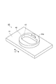
- FIG. 3 is a perspective view showing an example of the sample container in the spectrometer of FIG. 1
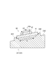
- FIG. 4 is a cross-sectional view showing an example of the sample container holder in the spectrometer of FIG. 1
- FIG. 5 shows the sample container holder of FIG. It is the top view seen from the installation surface side.
- the sample container 40 is used for quantum yield measurement using the integrating sphere 20, and has a rectangular plate-like (for example, rectangular) collar (plate) 41; It has a convex part 42 provided on the flange part 41 and an accommodating part 43 as a concave part provided in the convex part 42 for accommodating the sample 1.
- the shape of the collar part 41 is not limited to a rectangular shape, but may be other shapes such as a circular shape or an elliptical shape.
- a sample container 40 can be manufactured by fixing a columnar member having a through hole in the center portion on a plate member (plate-like member) by adhesion or the like. As a result, the portion of the plate member to which the cylindrical member is not bonded becomes the flange portion 41, and the through hole of the cylindrical member becomes the accommodating portion 43 as a concave portion for accommodating the sample 1. According to such a manufacturing method, the sample container 40 can be manufactured relatively easily.
- the sample container 40 is preferably made of a transparent material such as quartz or synthetic quartz, for example, for suppressing light absorption by the sample container 40. Note that the sample container 40 may not be completely transparent.
- the convex portion 42 has a circular outer shape when viewed from above, and has a circular cross section.
- the housing portion 43 has an elongated oval shape in the longitudinal direction of the flange portion 41 (in other words, a track shape having the same long axis as the flange portion 41) when viewed from above. That is, the major axis direction L1 of the surface (hereinafter referred to as the opening surface 43a of the accommodating portion 43) due to the opening of the accommodating portion 43 is the same as the major axis direction L2 of the flange portion 41.
- the shape of the opening surface 43a of the accommodating part 43 is not restricted to an ellipse shape, What is necessary is just a shape which has a long axis, such as a rectangular shape and an ellipse shape. Since the shape of the opening surface 43a of the accommodating portion 43 has a long axis, the opening area can be increased.
- the accommodating portion 43 accommodates the sample 1 so that the excitation light L applied to the sample 1 includes the sample 1 (see FIG. 5).
- the sample container holder 24 holds the sample container 40 in the integrating sphere 20.
- the portion of the sample container holder 24 that is introduced into the integrating sphere 20 is coated with the same highly diffuse reflective material as the inner wall of the integrating sphere 20.
- the sample container holder 24 includes a mounting table (inclined member) 241, and the mounting table 241 has a mounting surface 242 on which the sample container 40 is mounted.
- the mounting surface 242 is formed to be inclined with respect to a vertical surface (orthogonal surface) of the irradiation optical axis when the sample container holder 24 is attached to the sample introduction opening 23.
- the opening surface 43a of the housing portion 43 can be inclined with respect to the plane orthogonal to the irradiation optical axis.
- a positioning portion 243 as a convex portion protruding upward is formed in the vicinity of the outer periphery.
- the positioning portions 243 are arranged at four locations at intervals corresponding to the outer shape of the flange portion 41 of the sample container 40. These positioning portions 243 have a prismatic shape in which a corner portion on the inner upper side is cut out.
- the tilt direction of the mounting table 241 is also positioned in the same direction as the major axis direction of the accommodating portion 43 in the sample container 40 arranged, the tilt direction and the major axis direction of the accommodating portion 43 are the same direction. Become.
- FIG. 6 is a diagram for explaining the relationship between the aperture and the accommodating portion.
- the relationship between the major axis direction of the aperture 213 and the inclination direction of the accommodating portion 43 (the major axis direction of the opening surface 43a of the accommodating portion 43) and the effects thereof will be described with reference to FIG.
- the excitation light L is shaped into a shape having a long axis (for example, a rectangular shape) by the opening of the aperture 213 and propagates while spreading in the integrating sphere 20.
- the orthogonal plane of the irradiation optical axis of the excitation light L has a shape having a long axis, and the long axis direction of the aperture 213 and the orthogonal plane of the irradiation optical axis are in the same direction.
- the opening surface 43a of the accommodating portion 43 of the sample container 40 is inclined with respect to the orthogonal plane of the irradiation optical axis, and the sample
- the inclination direction of the opening surface 43a of the container portion 43 of the container 40 and the major axis direction of the opening surface 43a are the same direction (that is, the major axis direction of the opening of the aperture 213 and the inclination direction of the opening surface 43a of the container portion 43 (or , Long axis direction) intersect with an angle).
- the irradiation region of the excitation light L is shaped by the aperture 213 and becomes longer than the shape, so that it becomes easier to enclose the accommodating portion 43 of the sample container 40.
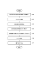
- the sample container holder 24 in which the sample container 40 is not installed (that is, the sample 1 is not present) is attached to the sample introduction opening 23 (S1).
- the sample container holder 24 functions as a part of the inner wall of the integrating sphere 20.
- reference measurement which is spectroscopic measurement in a state where the sample 1 is not arranged in the integrating sphere 20, is performed (S2).
- the excitation light source 11 light is emitted from the excitation light source 11, and the excitation light L is guided from the incident opening 21 into the integrating sphere 20 by the incident light guide 12. Then, the light to be measured that has been diffusely reflected and reflected within the integrating sphere 20 is guided from the exit opening 22 to the spectroscopic analyzer 30 by the exit light guide 125, and the spectroscopic analyzer 30 causes the wavelength spectrum 15a (FIG. 9A). Browse). Since the wavelength spectrum 15a has an intensity in the excitation wavelength region, the data analyzer 50 integrates the excitation wavelength region intensity to obtain the excitation light region intensity La.
- the sample 1 is accommodated in the sample container 40 (S3). That is, as shown in FIG. 8A, the annular plate-shaped accommodation auxiliary cover 45 is attached to the sample container 40. Specifically, the accommodation auxiliary cover 45 is placed on the collar 41 while the projection 42 is inserted and fitted into the opening 46 having a shape corresponding to the cross-sectional outline of the projection 42 in the accommodation auxiliary cover 45. The upper side of the part 41 is covered.
- the accommodating auxiliary cover 45 has the same thickness as the convex portion 42 or smaller than that. Moreover, since the sample 1 often has a color tone such as yellow, the storage auxiliary cover 45 has a black color as preferable for grasping the position of the sample 1.
- the shape of the storage auxiliary cover 45 is not limited to an annular plate shape, but the shape of the opening 46 is preferably circular.
- the sample 1 is accommodated in the accommodating portion 43 of the sample container 40 with the accommodating auxiliary cover 45 attached. Then, the surface of the sample 1 is leveled with a metal brush or the like to flatten the exposed portion of the sample 1, and then the storage auxiliary cover 45 is removed from the sample container 40 with tweezers or the like. When the sample 1 is flattened, the extra sample 1 is placed on the auxiliary storage cover 45 so that it can be removed when the auxiliary auxiliary cover 45 is removed. Thereby, it can prevent that the sample 1 adheres to parts other than the accommodating part 43 of the sample container 40.
- a sample cover (not shown) is placed on the convex portion 42 of the sample container 40, and the sample container 40 is placed on the placing table 241 of the sample container holder 24 as shown in FIGS. 4 and 5 (S4).
- the sample container 40 is disposed in the four positioning portions 243 and is locked to the positioning portions 243.
- the sample container 40 is positioned and fixed on the sample container holder 24 so that the sample container 40 is oriented in a predetermined direction.
- the long axis direction of the flange 41 of the sample container 40 and the length of the storage part 43 are fixed.
- the sample container holder 24 in which the sample container 40 is installed is attached to the sample introduction opening 23 (S5).
- positioned the sample 1 in the integrating sphere 20 is performed (S6).
- the excitation light source 11 light is emitted from the excitation light source 11, and the excitation light L is guided from the incident opening 21 into the integrating sphere 20 by the incident light guide 12, so that the excitation light L is transmitted onto the sample container holder 24.
- the sample 1 is irradiated.
- the excitation light L passes through the aperture 213 through the collimator lens, and is irradiated on the sample 1 in a rectangular shape while spreading in the integrating sphere 20.
- the excitation light L is irradiated so as to enclose the sample 1.
- the aperture 213 preferably has an opening having a shape having a long axis.
- Examples of the shape having the long axis include an elliptical shape and a rectangular shape.
- the major axis direction of the opening of the aperture 213 and the major axis direction of the plane orthogonal to the irradiation optical axis of the excitation light L are the same direction. Therefore, the major axis direction of the opening of the aperture 213 and the inclination direction K2 (major axis direction) of the accommodating portion 43 of the sample container 40 intersect with each other with an angle.
- the light to be measured includes light emission such as fluorescence generated in the sample 1 by the irradiation of the excitation light L, and light components scattered and reflected by the sample 1 in the excitation light L.
- the data analyzer 50 integrates the excitation wavelength region intensity in the wavelength spectrum 15b to obtain the excitation light region intensity Lb, and also integrates the fluorescence wavelength region intensity to obtain the fluorescence region intensity Lc.
- the excitation light region intensity Lb decreases as the excitation light L is absorbed by the sample 1
- the fluorescence region intensity Lc is the amount of fluorescence generated from the sample 1.
- the quantum yield is calculated by the data analysis device 50 based on the acquired intensities La, Lb, and Lc (S7).
- the quantum yield is expressed by the ratio between the number of photons emitted from the sample 1 and the number of photons of the excitation light L absorbed by the sample 1, so that “the external quantum efficiency of the sample 1 (generated from the sample 1 (Fluorescence amount) "/" light absorption rate of sample 1 (excitation light amount absorbed by sample 1) ". Therefore, in S7, for example, the light absorption rate is calculated based on the difference between the excitation light region intensities La and Lb, and the external quantum efficiency related to the fluorescence region intensity Lc is divided by the light absorption rate, thereby obtaining the quantum yield.
- the analysis result is displayed on the display device 62, and the measurement is terminated.
- the device correction coefficient used for the device correction can be obtained in advance and stored in the data analysis device 50, for example. Thereby, the influence of the spectroscopic measurement apparatus 100 ⁇ / b> A itself can be suitably taken into consideration for the spectroscopic measurement of the sample 1.
- the container correction relating to the light absorption by the sample container 40 can be performed on the wavelength spectra 15a and 15b.
- the container correction coefficient used for container correction can be calculated, for example, by performing reference measurement and sample measurement using white light separately from the spectroscopic measurement of sample 1 (S2 and S6 above). As a result, the influence of light absorption by the sample container 40 can be suitably taken into account for the spectroscopic measurement of the sample 1.
- the self-absorption amount can be reduced and the quantum yield can be accurately obtained for the following reason. That is, when a part of the sample 1 is irradiated with the excitation light L, the amount of self-absorption is large because the boundary area between the irradiated region and the non-irradiated region in the sample 1 is large. Because the excitation light L is irradiated so as to include the entire sample 1, the boundary area between the irradiated region and the non-irradiated region in the sample 1 becomes narrow, and the self-absorption amount becomes small.
- the amount of the sample 1 required increases, and a part of the sample 1 is irradiated with the excitation light L. There is a tendency to increase.
- the sample container 40 of the present embodiment a small amount of the sample 1 can be accommodated and the excitation light L can be irradiated so as to wrap the entire sample 1. The yield can be accurately measured. That is, this embodiment can measure even a small amount of sample in the quantum yield measurement using the integrating sphere 20.
- the amount of the sample 1 to be stored tends to vary depending on the user.
- the sample container 40 of the present embodiment is used, the amount of the sample 1 can be quantified, and thus differs.
- the measurement data of the sample 1 can be easily compared.
- the sample 1 is more easily separated than the sample container 40, so at least in terms of ease of use. Not practical.
- the sample container 40 is configured to be inclined with respect to the vertical plane of the irradiation optical axis. Thereby, it is possible to suppress the excitation light L that has entered the integrating sphere 20 from the incident opening 21 from being reflected by the sample 1 and emitted from the incident opening 21. As a result, the light to be measured from the sample 1 and the excitation light L reflected by the sample 1 can be actively multiple-reflected in the integrating sphere 20, and the quantum yield can be measured more accurately.
- the accommodation auxiliary cover 45 can prevent the sample 1 from adhering to the flange portion 41, and the inner wall of the integrating sphere 20 and the sample can be prevented. It is possible to suppress the sample 1 from adhering to the highly diffuse reflection material applied to the container holder 24. Moreover, since the major axis of the accommodating part 43 of the sample container 40 is set in the same direction as the major axis of the flange 41, the direction of the accommodating part 43 can be uniquely determined when the sample container 40 is attached. .
- the position of the exit opening 22 of the integrating sphere body 200 is not particularly limited, and may be any position as long as the light to be measured from the sample 1 is not directly incident.
- a lens that spreads the excitation light L from the light emitting section 7 may be further provided so that the excitation light L includes the sample 1.
- the collimator lens 212 and the aperture 213 are provided as the incident optical system, only one of them may be provided.
- the incident optical system may be configured to include (or only) the emission end portion of the incident light guide 12.
- FIG. 11 is a cross-sectional view showing a spectroscopic measurement apparatus according to a modification.
- the spectroscopic measurement apparatus 100 ⁇ / b> B according to the modification has a configuration that can irradiate the sample 1 with the excitation light L from an oblique direction.
- Such a spectroscopic measurement apparatus 100 ⁇ / b> B includes a dark box 5.
- the dark box 5 is a rectangular parallelepiped box made of metal and blocks light from entering from the outside.
- the inner surface 5a of the dark box 5 is coated with a material that absorbs the excitation light L and the light to be measured.
- An integrating sphere 14 is disposed in the dark box 5.
- the integrating sphere 14 is coated with a highly diffuse reflector such as barium sulfate on the inner surface 14a, or is formed of a material such as PTFE or Spectralon.
- the integrating sphere 14 is connected to a light detector (not shown, a light detector) through an emission opening.
- a light emitting part 7 of a light generating part (not shown) is connected to one side wall of the dark box 5.
- the light generation unit is an excitation light source configured by, for example, a xenon lamp or a spectroscope, and generates the excitation light L.
- the excitation light L is collimated by the lens 8 provided in the light emitting unit 7 and enters the dark box 5.
- a collimator lens 64 and mirrors 65 and 66 are arranged in this order from upstream to downstream in the irradiation optical axis.
- An aperture 67 is provided in the incident aperture 21 of the integrating sphere 14.
- the aperture 67 has an opening having a shape having a long axis, and a notch 67 a is formed in at least a part of the opening of the aperture 67.
- the shape of the notch 67a is formed so that the excitation light L that passes through the aperture 67 and enters the sample 1 is wider than the region of the sample 1 (the area of the sample 1 when viewed from above).
- the collimator lens 64, the mirrors 65 and 66, and the aperture 67 constitute an incident optical system for causing the excitation light L to enter the sample 1.
- the excitation light L incident on the dark box 5 is collimated by the collimator lens 64, is sequentially reflected by the mirrors 65 and 66, passes through the aperture 67, and is incident on the integrating sphere 14.
- the excitation light L is applied to the sample container 40 so as to enclose the sample 1 in the integrating sphere 14.
- the mirror 66 changes the incident angle of the irradiation light axis of the excitation light L so that the orthogonal surface (vertical surface) of the irradiation light axis of the excitation light L is inclined with respect to the opening surface 43a of the accommodating portion 43 of the sample container 40.
- the inclination direction of the opening surface 43a of the accommodating part 43 with respect to the orthogonal plane of the irradiation light axis of the excitation light L and the major axis direction L1 (see FIG. 3) of the opening surface 43a of the accommodating part 43 are the same direction.
- a lens that spreads the excitation light L from the light emitting unit 7 may be provided so that the excitation light L includes the sample 1.
- the collimator lens 64, the mirrors 65 and 66, and the aperture 67 are provided as the incident optical system, only the aperture 67 may be provided.
- the incident optical system may be configured including (or only) the emission end part of the light emitting part 7.
- the integrating sphere 14 is used as an integrator, but any means (optical component) for spatially integrating the light inside the integrating sphere 14 may be used.
- any means (optical component) for spatially integrating the light inside the integrating sphere 14 may be used.
- An integrated hemisphere may be used.
- the excitation light L may be configured to include the sample 1.
- at least one of the incident optical system of the excitation light L and the shape of the housing portion 43 of the sample container 40 is adjusted.
- the excitation light L may include the sample 1.
- the sample container holder 24 which is a sample holder attached to an integrator hold maintained the sample container 40 which has the accommodating part 43, even if the sample container holder 24 which has the accommodating part 43 is attached to an integrator, Good.
- the quantum yield (efficiency) measurement was mainly mentioned as an object of a spectrometer and a spectroscopy measurement method, it is not restricted to this, It is good also considering a reflectance measurement, a transmittance
- the quantum yield can be obtained with high accuracy.
Landscapes
- Physics & Mathematics (AREA)
- Spectroscopy & Molecular Physics (AREA)
- General Physics & Mathematics (AREA)
- Health & Medical Sciences (AREA)
- Pathology (AREA)
- Life Sciences & Earth Sciences (AREA)
- Chemical & Material Sciences (AREA)
- Analytical Chemistry (AREA)
- Biochemistry (AREA)
- General Health & Medical Sciences (AREA)
- Immunology (AREA)
- Nuclear Medicine, Radiotherapy & Molecular Imaging (AREA)
- Investigating, Analyzing Materials By Fluorescence Or Luminescence (AREA)
- Spectrometry And Color Measurement (AREA)
- Optical Measuring Cells (AREA)
- Investigating Or Analysing Materials By Optical Means (AREA)
Abstract
Description
Diode)用やFPD(Flat Panel Display)用等の発光材料等の蛍光試料であり、例えば粉末状、液体状(溶液状)、固体状又は薄膜状のもの等を用いることができる。
Claims (14)
- 測定対象となる試料に励起光を照射し、被測定光を検出する分光測定装置であって、
前記励起光を発生させる光源と、
前記励起光が入射される入射開口部と、前記被測定光を出射する出射開口部とを有する積分器と、
前記積分器内に配置され、前記試料を収容する収容部と、
前記試料に前記励起光を入射させる入射光学系と、
前記出射開口部から出射された前記被測定光を検出する光検出器と、
前記光検出器で検出された検出値に基づき前記試料の量子収率を算出する解析手段と、を備え、
前記励起光は、前記試料を内包するように当該試料に照射される、分光測定装置。 - 前記入射光学系は、前記励起光が前記試料を内包するように前記励起光を調整する、請求項1に記載の分光測定装置。
- 前記収容部は、前記励起光が前記試料を内包するように前記試料を収容する、請求項1又は2に記載の分光測定装置。
- 前記積分器は、前記収容部を前記積分器内に配置するための試料ホルダが取り付けられる試料導入開口部を有し、
前記試料ホルダは、前記励起光における照射光軸の直交面に対し前記収容部の開口面が傾斜するように前記試料導入開口部に取り付けられる、請求項1~3の何れか一項に記載の分光測定装置。 - 前記収容部の前記開口面の傾斜方向と前記収容部の開口面の長軸方向とは、互いに同方向である、請求項4に記載の分光測定装置。
- 前記入射光学系は、長軸を有する形状の開口を有する光学部材を備え、
前記光学部材の開口の長軸方向と前記収容部の開口面の傾斜方向とは、角度を有する、請求項4又は5に記載の分光測定装置。 - 前記試料ホルダは、
前記収容部を含む試料容器を載置するための載置面を有し、
前記励起光における照射光軸の直交面に対し前記載置面が傾斜するように、前記試料導入開口部に取り付けられる、請求項4~6の何れか一項に記載の分光測定装置。 - 前記試料ホルダは、前記載置面を有する傾斜部材を備える、請求項7に記載の分光測定装置。
- 前記入射光学系は、前記収容部の開口面に対する照射光軸の角度を調整する光学部材を有する、請求項4又は5に記載の分光測定装置。
- 測定対象となる試料に励起光を照射し、被測定光を検出する分光測定方法であって、
積分器内に前記試料を配置する工程と、
前記励起光が前記試料を内包するように、前記積分器内へ前記励起光を照射して前記試料に入射させる工程と、
前記積分器から出射された前記被測定光を検出する工程と、
検出された前記被測定光に基づき前記試料の量子収率を算出する工程と、を含む、分光測定方法。 - 積分器を利用した量子収率測定に用いられる試料容器であって、
矩形板状の板部と、
前記板部上に設けられた凸部と、
前記凸部に設けられ、測定対象となる試料を収容する収容部と、を備え、
前記収容部は、前記試料に照射される励起光が前記試料を内包するように、前記試料を収容する、試料容器。 - 前記凸部の断面は、円形状である、請求項11に記載の試料容器。
- 前記収容部の開口は、長軸を有する形状である、請求項11に記載の試料容器。
- 貫通孔を有する円柱部材を、板状部材の面上に固定されることで形成される前記試料容器であって、
前記板部が前記板状部材で構成され、前記凸部が前記円柱部材で構成され、前記収容部が前記貫通孔で構成される、請求項11~13の何れか一項に記載の試料容器。
Priority Applications (5)
| Application Number | Priority Date | Filing Date | Title |
|---|---|---|---|
| KR1020157016500A KR20150090149A (ko) | 2013-02-04 | 2013-09-17 | 분광 측정 장치, 분광 측정 방법 및 시료 용기 |
| CN201380072255.2A CN104969061B (zh) | 2013-02-04 | 2013-09-17 | 分光测定装置、分光测定方法及试样容器 |
| KR1020187007646A KR20180031809A (ko) | 2013-02-04 | 2013-09-17 | 분광 측정 장치, 분광 측정 방법 및 시료 용기 |
| US14/764,703 US10209189B2 (en) | 2013-02-04 | 2013-09-17 | Spectrum measuring device, spectrum measuring method, and specimen container |
| EP13873636.8A EP2952881B1 (en) | 2013-02-04 | 2013-09-17 | Spectrum measuring device, spectrum measuring method, and specimen container |
Applications Claiming Priority (2)
| Application Number | Priority Date | Filing Date | Title |
|---|---|---|---|
| JP2013019409A JP5529305B1 (ja) | 2013-02-04 | 2013-02-04 | 分光測定装置、及び分光測定方法 |
| JP2013-019409 | 2013-02-04 |
Publications (1)
| Publication Number | Publication Date |
|---|---|
| WO2014119038A1 true WO2014119038A1 (ja) | 2014-08-07 |
Family
ID=51175795
Family Applications (1)
| Application Number | Title | Priority Date | Filing Date |
|---|---|---|---|
| PCT/JP2013/075033 WO2014119038A1 (ja) | 2013-02-04 | 2013-09-17 | 分光測定装置、分光測定方法、及び試料容器 |
Country Status (7)
| Country | Link |
|---|---|
| US (1) | US10209189B2 (ja) |
| EP (1) | EP2952881B1 (ja) |
| JP (1) | JP5529305B1 (ja) |
| KR (2) | KR20150090149A (ja) |
| CN (1) | CN104969061B (ja) |
| TW (1) | TWI613434B (ja) |
| WO (1) | WO2014119038A1 (ja) |
Cited By (1)
| Publication number | Priority date | Publication date | Assignee | Title |
|---|---|---|---|---|
| WO2016088574A1 (ja) * | 2014-12-02 | 2016-06-09 | 浜松ホトニクス株式会社 | 分光測定装置および分光測定方法 |
Families Citing this family (16)
| Publication number | Priority date | Publication date | Assignee | Title |
|---|---|---|---|---|
| JP5944843B2 (ja) * | 2013-02-04 | 2016-07-05 | 浜松ホトニクス株式会社 | 分光測定装置及び分光測定方法 |
| CN109341857A (zh) * | 2014-12-02 | 2019-02-15 | 浜松光子学株式会社 | 分光测定装置及分光测定方法 |
| KR101802462B1 (ko) * | 2016-04-21 | 2017-11-28 | 서울대학교산학협력단 | 각도의존성 광발광 측정장치 |
| JP6227067B1 (ja) | 2016-07-25 | 2017-11-08 | 浜松ホトニクス株式会社 | 光計測装置 |
| JP6227068B1 (ja) * | 2016-07-27 | 2017-11-08 | 浜松ホトニクス株式会社 | 試料容器保持部材、光計測装置及び試料容器配置方法 |
| JP6943618B2 (ja) * | 2017-05-17 | 2021-10-06 | 浜松ホトニクス株式会社 | 分光測定装置及び分光測定方法 |
| JP6920887B2 (ja) * | 2017-06-02 | 2021-08-18 | 浜松ホトニクス株式会社 | 光計測装置および光計測方法 |
| RU2753446C1 (ru) * | 2018-03-14 | 2021-08-16 | Грейнсенс Ой | Контейнеры для образцов для применения внутри интегрирующих камер и соответствующие приспособления |
| CN108827918B (zh) * | 2018-05-29 | 2024-07-26 | 天津九光科技发展有限责任公司 | 基于积分球的漫反射光谱测量装置、测量方法及校正方法 |
| JP6492220B1 (ja) * | 2018-09-26 | 2019-03-27 | 大塚電子株式会社 | 測定システムおよび測定方法 |
| CN109612969B (zh) * | 2018-12-12 | 2021-07-27 | 闽江学院 | 一种可用于长余辉发光物的光色测量装置及测试方法 |
| JP6763995B2 (ja) * | 2019-04-18 | 2020-09-30 | 浜松ホトニクス株式会社 | 分光測定装置および分光測定方法 |
| CN110056842B (zh) * | 2019-06-06 | 2021-01-05 | 中国科学院长春光学精密机械与物理研究所 | 一种单星模拟器及其光源 |
| CN112665826A (zh) * | 2019-10-15 | 2021-04-16 | 成都辰显光电有限公司 | 积分球检测器 |
| JP6751214B1 (ja) | 2020-02-12 | 2020-09-02 | デクセリアルズ株式会社 | 測定装置及び成膜装置 |
| CN113607663B (zh) * | 2021-07-06 | 2024-07-23 | 武汉理工大学 | 漫反射式多用途多变量耦合原位光学吸收测试装置及方法 |
Citations (9)
| Publication number | Priority date | Publication date | Assignee | Title |
|---|---|---|---|---|
| US4583860A (en) * | 1983-11-30 | 1986-04-22 | The United States Of America As Represented By The Administrator Of The National Aeronautics And Space Administration | Optical multiple sample vacuum integrating sphere |
| JPH068526Y2 (ja) * | 1987-12-14 | 1994-03-02 | 通商産業省工業技術院長 | 粉体試料用プレパラート |
| JP2003215041A (ja) | 2002-01-24 | 2003-07-30 | National Institute Of Advanced Industrial & Technology | 固体試料の絶対蛍光量子効率測定方法及び装置 |
| JP2004309323A (ja) * | 2003-04-08 | 2004-11-04 | Oputeru:Kk | 発光素子の絶対量子効率測定方法及び装置 |
| JP2007086031A (ja) * | 2005-09-26 | 2007-04-05 | Hamamatsu Photonics Kk | 光検出装置、及び試料ホルダ用治具 |
| JP2009103654A (ja) | 2007-10-25 | 2009-05-14 | Otsuka Denshi Co Ltd | 光束計および測定方法 |
| JP3165429U (ja) * | 2010-11-02 | 2011-01-20 | 誠 山口 | 微細バブル観察用試料ホルダー |
| JP2011196735A (ja) | 2010-03-18 | 2011-10-06 | Otsuka Denshi Co Ltd | 量子効率測定方法、量子効率測定装置、および積分器 |
| WO2012073567A1 (ja) * | 2010-11-29 | 2012-06-07 | 浜松ホトニクス株式会社 | 量子収率測定装置 |
Family Cites Families (16)
| Publication number | Priority date | Publication date | Assignee | Title |
|---|---|---|---|---|
| US4765718A (en) * | 1987-11-03 | 1988-08-23 | General Electric Company | Collimated light source for liquid crystal display utilizing internally reflecting light pipe collimator with offset angle correction |
| GB9511490D0 (en) * | 1995-06-07 | 1995-08-02 | Renishaw Plc | Raman microscope |
| JP3353560B2 (ja) * | 1995-08-24 | 2002-12-03 | ミノルタ株式会社 | 反射特性測定装置 |
| US7394551B2 (en) * | 2003-01-16 | 2008-07-01 | Metrosol, Inc. | Vacuum ultraviolet referencing reflectometer |
| JP5058489B2 (ja) * | 2006-01-25 | 2012-10-24 | 株式会社荏原製作所 | 試料表面検査装置及び検査方法 |
| WO2008107947A1 (ja) * | 2007-03-01 | 2008-09-12 | Hamamatsu Photonics K.K. | 光検出装置、及び試料ホルダ用治具 |
| WO2009050536A1 (en) * | 2007-10-15 | 2009-04-23 | Ecole Polytechnique Federale De Lausanne (Epfl) | Integrating sphere for the optical analysis of luminescent materials |
| JP5148387B2 (ja) * | 2008-06-30 | 2013-02-20 | 浜松ホトニクス株式会社 | 分光測定装置、分光測定方法、及び分光測定プログラム |
| JP5161755B2 (ja) | 2008-12-25 | 2013-03-13 | 浜松ホトニクス株式会社 | 分光測定装置、分光測定方法、及び分光測定プログラム |
| DE102009025561A1 (de) * | 2009-06-12 | 2010-12-16 | BAM Bundesanstalt für Materialforschung und -prüfung | Anordnung und Verfahren zur Bestimmung der Lumineszenzquantenausbeute einer lumineszierenden Probe |
| JP4835730B2 (ja) | 2009-08-06 | 2011-12-14 | 横河電機株式会社 | 蛍光量または吸光量の測定方法および測定装置 |
| FR2960642B1 (fr) * | 2010-05-28 | 2012-07-13 | Snecma | Procede de controle non destructif et dispositif de mise en oeuvre du procede |
| JP5296034B2 (ja) | 2010-11-10 | 2013-09-25 | 浜松ホトニクス株式会社 | 光検出装置及び試料ホルダ |
| JP5588485B2 (ja) | 2012-09-13 | 2014-09-10 | 浜松ホトニクス株式会社 | 分光測定装置、分光測定方法、及び分光測定プログラム |
| JP5944843B2 (ja) * | 2013-02-04 | 2016-07-05 | 浜松ホトニクス株式会社 | 分光測定装置及び分光測定方法 |
| US10203246B2 (en) * | 2015-11-20 | 2019-02-12 | Verifood, Ltd. | Systems and methods for calibration of a handheld spectrometer |
-
2013
- 2013-02-04 JP JP2013019409A patent/JP5529305B1/ja active Active
- 2013-09-17 CN CN201380072255.2A patent/CN104969061B/zh active Active
- 2013-09-17 US US14/764,703 patent/US10209189B2/en active Active
- 2013-09-17 KR KR1020157016500A patent/KR20150090149A/ko active Application Filing
- 2013-09-17 WO PCT/JP2013/075033 patent/WO2014119038A1/ja active Application Filing
- 2013-09-17 EP EP13873636.8A patent/EP2952881B1/en active Active
- 2013-09-17 KR KR1020187007646A patent/KR20180031809A/ko not_active Application Discontinuation
- 2013-09-30 TW TW102135402A patent/TWI613434B/zh active
Patent Citations (9)
| Publication number | Priority date | Publication date | Assignee | Title |
|---|---|---|---|---|
| US4583860A (en) * | 1983-11-30 | 1986-04-22 | The United States Of America As Represented By The Administrator Of The National Aeronautics And Space Administration | Optical multiple sample vacuum integrating sphere |
| JPH068526Y2 (ja) * | 1987-12-14 | 1994-03-02 | 通商産業省工業技術院長 | 粉体試料用プレパラート |
| JP2003215041A (ja) | 2002-01-24 | 2003-07-30 | National Institute Of Advanced Industrial & Technology | 固体試料の絶対蛍光量子効率測定方法及び装置 |
| JP2004309323A (ja) * | 2003-04-08 | 2004-11-04 | Oputeru:Kk | 発光素子の絶対量子効率測定方法及び装置 |
| JP2007086031A (ja) * | 2005-09-26 | 2007-04-05 | Hamamatsu Photonics Kk | 光検出装置、及び試料ホルダ用治具 |
| JP2009103654A (ja) | 2007-10-25 | 2009-05-14 | Otsuka Denshi Co Ltd | 光束計および測定方法 |
| JP2011196735A (ja) | 2010-03-18 | 2011-10-06 | Otsuka Denshi Co Ltd | 量子効率測定方法、量子効率測定装置、および積分器 |
| JP3165429U (ja) * | 2010-11-02 | 2011-01-20 | 誠 山口 | 微細バブル観察用試料ホルダー |
| WO2012073567A1 (ja) * | 2010-11-29 | 2012-06-07 | 浜松ホトニクス株式会社 | 量子収率測定装置 |
Non-Patent Citations (3)
| Title |
|---|
| "Theoretic study on absolute fluorescence quantum efficiency measurement method using integrating sphere", THE 71ST JSAP MEETING, 12 September 2010 (2010-09-12) |
| JOHN C. DE MELLO; H. FELIX WITTMANN; RICHARD H. FRIEND: "An improved experimental determination of external photoluminescence quantum efficiency", ADVANCED MATERIALS, vol. 9, no. 3, March 1997 (1997-03-01), pages 230 - 232 |
| N.C. GREENHAM; I.D.W. SAMUEL; G.R. HAYES; R.T. PHILLIPS; Y.A.R.R. KESSENER; S.C. MORATTI; A.B. HOLMES; R.H. FRIEND: "Measurement of absolute photoluminescence quantum efficiencies in conjugated polymers", CHEMICAL PHYSICS LETTERS, vol. 241, no. 1-2, 14 July 1995 (1995-07-14), pages 89 - 96 |
Cited By (4)
| Publication number | Priority date | Publication date | Assignee | Title |
|---|---|---|---|---|
| WO2016088574A1 (ja) * | 2014-12-02 | 2016-06-09 | 浜松ホトニクス株式会社 | 分光測定装置および分光測定方法 |
| JP2016109432A (ja) * | 2014-12-02 | 2016-06-20 | 浜松ホトニクス株式会社 | 分光測定装置および分光測定方法 |
| US10036706B2 (en) | 2014-12-02 | 2018-07-31 | Hamamatsu Photonics K.K. | Spectrometry device and spectrometry method |
| US10222332B2 (en) | 2014-12-02 | 2019-03-05 | Hamamatsu Photonics K.K. | Spectrometry device and spectrometry method |
Also Published As
| Publication number | Publication date |
|---|---|
| TWI613434B (zh) | 2018-02-01 |
| US20150346096A1 (en) | 2015-12-03 |
| EP2952881A4 (en) | 2016-08-10 |
| TW201432247A (zh) | 2014-08-16 |
| JP2014149267A (ja) | 2014-08-21 |
| KR20150090149A (ko) | 2015-08-05 |
| EP2952881B1 (en) | 2020-09-02 |
| JP5529305B1 (ja) | 2014-06-25 |
| KR20180031809A (ko) | 2018-03-28 |
| CN104969061A (zh) | 2015-10-07 |
| US10209189B2 (en) | 2019-02-19 |
| EP2952881A1 (en) | 2015-12-09 |
| CN104969061B (zh) | 2017-12-22 |
Similar Documents
| Publication | Publication Date | Title |
|---|---|---|
| JP5529305B1 (ja) | 分光測定装置、及び分光測定方法 | |
| TWI591323B (zh) | Spectrophotometer and spectrophotometer | |
| KR101716902B1 (ko) | 분광 측정 장치, 분광 측정 방법, 및 분광 측정 프로그램 | |
| JP6279399B2 (ja) | 光計測装置及び光計測方法 | |
| JP3682528B2 (ja) | 固体試料の絶対蛍光量子効率測定方法及び装置 | |
| WO2012073567A1 (ja) | 量子収率測定装置 | |
| WO2012073568A1 (ja) | 量子収率測定装置 | |
| JP4418731B2 (ja) | フォトルミネッセンス量子収率測定方法およびこれに用いる装置 | |
| KR20170092520A (ko) | 분광 측정 장치 및 분광 측정 방법 | |
| TWI683092B (zh) | 分光測定裝置及分光測定方法 | |
| JP6763995B2 (ja) | 分光測定装置および分光測定方法 | |
| KR20190032268A (ko) | 광 계측 장치 |
Legal Events
| Date | Code | Title | Description |
|---|---|---|---|
| 121 | Ep: the epo has been informed by wipo that ep was designated in this application |
Ref document number: 13873636 Country of ref document: EP Kind code of ref document: A1 |
|
| ENP | Entry into the national phase |
Ref document number: 20157016500 Country of ref document: KR Kind code of ref document: A |
|
| WWE | Wipo information: entry into national phase |
Ref document number: 14764703 Country of ref document: US |
|
| NENP | Non-entry into the national phase |
Ref country code: DE |
|
| WWE | Wipo information: entry into national phase |
Ref document number: 2013873636 Country of ref document: EP |