WO2014119038A1 - Spectrum measuring device, spectrum measuring method, and specimen container - Google Patents

Spectrum measuring device, spectrum measuring method, and specimen container Download PDF

Info

Publication number
WO2014119038A1
WO2014119038A1 PCT/JP2013/075033 JP2013075033W WO2014119038A1 WO 2014119038 A1 WO2014119038 A1 WO 2014119038A1 JP 2013075033 W JP2013075033 W JP 2013075033W WO 2014119038 A1 WO2014119038 A1 WO 2014119038A1
Authority
WO
WIPO (PCT)
Prior art keywords
sample
excitation light
light
opening
measured
Prior art date
Application number
PCT/JP2013/075033
Other languages
French (fr)
Japanese (ja)
Inventor
鈴木 健吾
和也 井口
茂 江浦
賢一郎 池村
Original Assignee
浜松ホトニクス株式会社
Priority date (The priority date is an assumption and is not a legal conclusion. Google has not performed a legal analysis and makes no representation as to the accuracy of the date listed.)
Filing date
Publication date
Application filed by 浜松ホトニクス株式会社 filed Critical 浜松ホトニクス株式会社
Priority to KR1020157016500A priority Critical patent/KR20150090149A/en
Priority to CN201380072255.2A priority patent/CN104969061B/en
Priority to KR1020187007646A priority patent/KR20180031809A/en
Priority to US14/764,703 priority patent/US10209189B2/en
Priority to EP13873636.8A priority patent/EP2952881B1/en
Publication of WO2014119038A1 publication Critical patent/WO2014119038A1/en

Links

Images

Classifications

    • GPHYSICS
    • G01MEASURING; TESTING
    • G01NINVESTIGATING OR ANALYSING MATERIALS BY DETERMINING THEIR CHEMICAL OR PHYSICAL PROPERTIES
    • G01N21/00Investigating or analysing materials by the use of optical means, i.e. using sub-millimetre waves, infrared, visible or ultraviolet light
    • G01N21/62Systems in which the material investigated is excited whereby it emits light or causes a change in wavelength of the incident light
    • G01N21/63Systems in which the material investigated is excited whereby it emits light or causes a change in wavelength of the incident light optically excited
    • G01N21/64Fluorescence; Phosphorescence
    • G01N21/645Specially adapted constructive features of fluorimeters
    • GPHYSICS
    • G01MEASURING; TESTING
    • G01JMEASUREMENT OF INTENSITY, VELOCITY, SPECTRAL CONTENT, POLARISATION, PHASE OR PULSE CHARACTERISTICS OF INFRARED, VISIBLE OR ULTRAVIOLET LIGHT; COLORIMETRY; RADIATION PYROMETRY
    • G01J3/00Spectrometry; Spectrophotometry; Monochromators; Measuring colours
    • G01J3/02Details
    • G01J3/0205Optical elements not provided otherwise, e.g. optical manifolds, diffusers, windows
    • G01J3/021Optical elements not provided otherwise, e.g. optical manifolds, diffusers, windows using plane or convex mirrors, parallel phase plates, or particular reflectors
    • GPHYSICS
    • G01MEASURING; TESTING
    • G01JMEASUREMENT OF INTENSITY, VELOCITY, SPECTRAL CONTENT, POLARISATION, PHASE OR PULSE CHARACTERISTICS OF INFRARED, VISIBLE OR ULTRAVIOLET LIGHT; COLORIMETRY; RADIATION PYROMETRY
    • G01J3/00Spectrometry; Spectrophotometry; Monochromators; Measuring colours
    • G01J3/02Details
    • G01J3/0205Optical elements not provided otherwise, e.g. optical manifolds, diffusers, windows
    • G01J3/0254Spectrometers, other than colorimeters, making use of an integrating sphere
    • GPHYSICS
    • G01MEASURING; TESTING
    • G01JMEASUREMENT OF INTENSITY, VELOCITY, SPECTRAL CONTENT, POLARISATION, PHASE OR PULSE CHARACTERISTICS OF INFRARED, VISIBLE OR ULTRAVIOLET LIGHT; COLORIMETRY; RADIATION PYROMETRY
    • G01J3/00Spectrometry; Spectrophotometry; Monochromators; Measuring colours
    • G01J3/02Details
    • G01J3/0291Housings; Spectrometer accessories; Spatial arrangement of elements, e.g. folded path arrangements
    • GPHYSICS
    • G01MEASURING; TESTING
    • G01JMEASUREMENT OF INTENSITY, VELOCITY, SPECTRAL CONTENT, POLARISATION, PHASE OR PULSE CHARACTERISTICS OF INFRARED, VISIBLE OR ULTRAVIOLET LIGHT; COLORIMETRY; RADIATION PYROMETRY
    • G01J3/00Spectrometry; Spectrophotometry; Monochromators; Measuring colours
    • G01J3/28Investigating the spectrum
    • G01J3/44Raman spectrometry; Scattering spectrometry ; Fluorescence spectrometry
    • G01J3/4406Fluorescence spectrometry
    • GPHYSICS
    • G01MEASURING; TESTING
    • G01JMEASUREMENT OF INTENSITY, VELOCITY, SPECTRAL CONTENT, POLARISATION, PHASE OR PULSE CHARACTERISTICS OF INFRARED, VISIBLE OR ULTRAVIOLET LIGHT; COLORIMETRY; RADIATION PYROMETRY
    • G01J3/00Spectrometry; Spectrophotometry; Monochromators; Measuring colours
    • G01J3/28Investigating the spectrum
    • G01J3/443Emission spectrometry
    • GPHYSICS
    • G01MEASURING; TESTING
    • G01NINVESTIGATING OR ANALYSING MATERIALS BY DETERMINING THEIR CHEMICAL OR PHYSICAL PROPERTIES
    • G01N21/00Investigating or analysing materials by the use of optical means, i.e. using sub-millimetre waves, infrared, visible or ultraviolet light
    • G01N21/01Arrangements or apparatus for facilitating the optical investigation
    • GPHYSICS
    • G01MEASURING; TESTING
    • G01NINVESTIGATING OR ANALYSING MATERIALS BY DETERMINING THEIR CHEMICAL OR PHYSICAL PROPERTIES
    • G01N21/00Investigating or analysing materials by the use of optical means, i.e. using sub-millimetre waves, infrared, visible or ultraviolet light
    • G01N21/62Systems in which the material investigated is excited whereby it emits light or causes a change in wavelength of the incident light
    • G01N21/63Systems in which the material investigated is excited whereby it emits light or causes a change in wavelength of the incident light optically excited
    • G01N21/64Fluorescence; Phosphorescence
    • G01N21/645Specially adapted constructive features of fluorimeters
    • G01N2021/6463Optics
    • G01N2021/6469Cavity, e.g. ellipsoid
    • GPHYSICS
    • G01MEASURING; TESTING
    • G01NINVESTIGATING OR ANALYSING MATERIALS BY DETERMINING THEIR CHEMICAL OR PHYSICAL PROPERTIES
    • G01N21/00Investigating or analysing materials by the use of optical means, i.e. using sub-millimetre waves, infrared, visible or ultraviolet light
    • G01N21/62Systems in which the material investigated is excited whereby it emits light or causes a change in wavelength of the incident light
    • G01N21/63Systems in which the material investigated is excited whereby it emits light or causes a change in wavelength of the incident light optically excited
    • G01N21/64Fluorescence; Phosphorescence
    • G01N21/645Specially adapted constructive features of fluorimeters
    • G01N2021/6482Sample cells, cuvettes
    • GPHYSICS
    • G01MEASURING; TESTING
    • G01NINVESTIGATING OR ANALYSING MATERIALS BY DETERMINING THEIR CHEMICAL OR PHYSICAL PROPERTIES
    • G01N21/00Investigating or analysing materials by the use of optical means, i.e. using sub-millimetre waves, infrared, visible or ultraviolet light
    • G01N21/62Systems in which the material investigated is excited whereby it emits light or causes a change in wavelength of the incident light
    • G01N21/63Systems in which the material investigated is excited whereby it emits light or causes a change in wavelength of the incident light optically excited
    • G01N21/64Fluorescence; Phosphorescence
    • G01N21/645Specially adapted constructive features of fluorimeters
    • G01N2021/6484Optical fibres
    • GPHYSICS
    • G01MEASURING; TESTING
    • G01NINVESTIGATING OR ANALYSING MATERIALS BY DETERMINING THEIR CHEMICAL OR PHYSICAL PROPERTIES
    • G01N21/00Investigating or analysing materials by the use of optical means, i.e. using sub-millimetre waves, infrared, visible or ultraviolet light
    • G01N21/62Systems in which the material investigated is excited whereby it emits light or causes a change in wavelength of the incident light
    • G01N21/63Systems in which the material investigated is excited whereby it emits light or causes a change in wavelength of the incident light optically excited
    • G01N21/64Fluorescence; Phosphorescence
    • G01N21/6489Photoluminescence of semiconductors
    • GPHYSICS
    • G01MEASURING; TESTING
    • G01NINVESTIGATING OR ANALYSING MATERIALS BY DETERMINING THEIR CHEMICAL OR PHYSICAL PROPERTIES
    • G01N2201/00Features of devices classified in G01N21/00
    • G01N2201/06Illumination; Optics
    • G01N2201/065Integrating spheres

Definitions

  • the present invention relates to a spectroscopic measurement apparatus, a spectroscopic measurement method, and a sample container.
  • Patent Document 1 describes a quantum efficiency measurement device. Yes.
  • the quantum efficiency measuring device described in Patent Document 1 the reflection component in the phosphor of single wavelength radiation and the total emission component of the excited fluorescence emission are integrated by an integrating sphere, and the spectral energy distribution is measured.
  • the total reflection component in the spectral reflectance standard of single wavelength radiation is integrated by an integrating sphere, and the spectral distribution is measured. Based on the measured value, the amount of photon absorbed by the phosphor and the amount of photon emitted from the fluorescent light are calculated, and the quantum yield of the phosphor is calculated from the ratio thereof.
  • Patent Document 2 when obtaining the quantum yield, the sample is fixed at a position where the excitation light does not directly hit in the integrating sphere, and the intensity obtained by injecting the excitation light indirectly to the sample, There is described an absolute fluorescence quantum efficiency measuring device for obtaining the absorption rate of a sample from the intensity obtained by direct incidence of excitation light on the sample.
  • Non-Patent Documents 1 to 3 describe that the quantum yield is calculated on the assumption that excitation light is incident on a part of the sample.
  • the quantum yield is represented by the ratio of the number of photons of the excitation light absorbed by the sample to the number of photons of the light to be measured. Therefore, when the light to be measured is absorbed by self-absorption, the quantum yield to be calculated is calculated. There is a possibility that the rate is estimated to be smaller than the true value.
  • an object of one aspect of the present invention is to provide a spectroscopic measurement apparatus, a spectroscopic measurement method, and a sample container that can accurately determine the quantum yield.
  • a spectroscopic measurement device is a spectroscopic measurement device that detects excitation light by irradiating a sample to be measured with excitation light, and a light source that generates the excitation light.
  • an integrator having an incident opening through which excitation light is incident and an output opening through which light to be measured is emitted, an accommodation unit disposed in the integrator for accommodating the sample, and the excitation light being incident on the sample
  • An incident optical system a photodetector for detecting the light to be measured emitted from the exit aperture, and an analysis means for calculating the quantum yield of the sample based on the detection value detected by the photodetector, The excitation light is irradiated on the sample so as to enclose the sample.
  • the self-absorption amount can be reduced, and the quantum yield can be obtained with high accuracy. This is due to the following reason. That is, when a part of the sample is irradiated with excitation light, the amount of self-absorption is large due to the large boundary area between the irradiated region and the non-irradiated region in the sample. This is because in the spectroscopic measurement apparatus, since the excitation light is irradiated so as to include the sample, the boundary area between the irradiated region and the non-irradiated region in the sample is narrowed, and the self-absorption amount is reduced.
  • the incident optical system adjusts the excitation light so that the excitation light encloses the sample
  • the structure in which the accommodating part accommodates a sample is mentioned so that excitation light may include a sample.
  • the integrator has a sample introduction opening to which a sample holder for placing the accommodation unit in the integrator is attached, and the sample holder has an opening surface of the accommodation unit with respect to a plane orthogonal to the irradiation optical axis in the excitation light. May be attached to the sample introduction opening so as to be inclined. In this case, the reflected light of the excitation light can be prevented from returning directly to the incident aperture.
  • the incident optical system may include an optical member having an opening having a shape having a major axis, and the major axis direction of the opening of the optical member and the inclination direction of the opening surface of the housing portion may have an angle. In these cases, the irradiation shape of the excitation light becomes more vertically long, and the accommodating portion can be surely included.
  • the sample holder has a mounting surface for mounting the sample container including the accommodating portion, and the sample introduction opening is arranged so that the mounting surface is inclined with respect to a plane orthogonal to the irradiation optical axis in the excitation light. May be attached.
  • the sample holder may include an inclined member having a placement surface.
  • the incident optical system may include an optical member that adjusts the angle of the irradiation optical axis with respect to the opening surface of the housing portion.
  • a spectroscopic measurement method is a spectroscopic measurement method of irradiating a sample to be measured with excitation light and detecting light to be measured, the step of arranging the sample in an integrator, Based on the detected light to be measured, the step of irradiating the sample with the excitation light so that the excitation light encloses the sample and making it incident on the sample, the step of detecting the light to be measured emitted from the integrator, and the detected light to be measured And a step of calculating a quantum yield of the sample.
  • a sample container is a sample container used for quantum yield measurement using an integrator, a rectangular plate-shaped plate portion, and a convex portion provided on the plate portion, And a storage unit that stores the sample to be measured, and the storage unit stores the sample so that the excitation light applied to the sample includes the sample.
  • the cross section of the convex portion may be circular, and the opening of the accommodating portion may be a shape having a long axis.
  • the sample container is formed by fixing a cylindrical member having a through hole on the surface of the plate-like member, the plate portion being constituted by the plate-like member, and the convex portion being the cylindrical member. In this case, the sample container can be manufactured relatively easily.
  • the quantum yield can be obtained with high accuracy.
  • FIG. 1 is a perspective view explaining accommodation of the sample in a storage container
  • (b) is a perspective view which shows the continuation of Fig.7
  • (a) is a graph which shows an example of the wavelength spectrum detected by reference measurement
  • (b) is a graph which shows an example of the wavelength spectrum detected by sample measurement.
  • (A) is a schematic diagram showing an example of the relationship between the irradiation area of the excitation light and the irradiated area of the sample
  • (b) is a schematic diagram showing another example of the relationship between the irradiation area of the excitation light and the irradiated area of the sample.
  • FIG. It is sectional drawing which shows the spectrometer which concerns on a modification.
  • FIG. 1 is a diagram schematically illustrating a configuration of a spectrometer according to an embodiment.
  • the spectroscopic measurement apparatus 100A measures or evaluates light emission characteristics such as fluorescence characteristics of a sample 1 as a sample to be measured by a photoluminescence method (PL method).
  • Sample 1 is, for example, an organic EL (Electroluminescence) material or a white LED (Light Emitting) It is a fluorescent sample such as a light emitting material for a diode or FPD (Flat Panel Display).
  • a powder, liquid (solution), solid or thin film can be used.
  • the spectroscopic measurement apparatus 100A irradiates the sample 1 with excitation light having a predetermined wavelength, and detects the light to be measured generated in response to the irradiation.
  • the spectroscopic measurement apparatus 100A includes an excitation light supply unit 10, an integrating sphere (integrator) 20, a spectroscopic analysis apparatus 30, and a data analysis apparatus 50.
  • the excitation light supply unit 10 is for irradiating the sample 1 with excitation light for measuring light emission characteristics.
  • the excitation light supply unit 10 includes at least an excitation light source (light source) 11, an incident light guide 12, and an optical filter 13.
  • the excitation light source 11 generates excitation light, and is composed of, for example, a xenon lamp or a spectroscope.
  • the incident light guide 12 guides the excitation light generated by the excitation light source 11 to the integrating sphere 20.
  • an optical fiber can be used as the incident light guide 12, for example.
  • the optical filter 13 selects a predetermined wavelength component from the light from the excitation light source 11, and emits excitation light of the predetermined wavelength component.
  • an interference filter or the like is used as the optical filter 13, a predetermined wavelength component.
  • the integrating sphere 20 introduces the sample 1 into the integrating sphere 20, an incident opening 21 for entering the excitation light into the integrating sphere 20, an exit opening 22 for emitting the measured light to the outside. And a sample introduction opening 23 for the purpose.
  • a sample container holder (sample holder) 24 is attached (fixed) to the sample introduction opening 23, and a sample container 40 for storing the sample 1 is placed on the sample container holder 24 in the integrating sphere 20. Being held.
  • the exit end of the incident light guide 12 is fixed to the incident opening 21, and the optical filter 13 is installed on the front side in the irradiation direction of the excitation light with respect to the incident light guide 12.
  • an incident end of an output light guide 25 that guides light to be measured to the subsequent spectroscopic analyzer 30 is fixed to the output opening 22.
  • the emission light guide 25 for example, a single fiber or a bundle fiber can be used.
  • the spectroscopic analyzer 30 separates the light to be measured emitted from the exit opening 22 of the integrating sphere 20 and guided by the exit light guide 25, and acquires the wavelength spectrum thereof.
  • the spectroscopic analysis device 30 here is configured as a multi-channel spectroscope having a spectroscopic unit 31 and a spectroscopic data generation unit 32.
  • the spectroscopic unit 31 includes a spectroscope 31a for decomposing measured light into wavelength components, and a photodetector 31b for detecting the measured light decomposed by the spectroscope 31a.
  • a photodetector 31b for example, a CCD linear sensor in which pixels of a plurality of channels (for example, 1024 channels) for detecting each wavelength component of the light to be measured are arranged one-dimensionally can be used.
  • the wavelength region measured by the spectroscopic unit 31 can be set as appropriate according to the specific configuration, application, and the like.
  • the spectral data generation unit 32 performs necessary signal processing on the detection signal output from each channel of the photodetector 31b, and generates wavelength spectrum data that is spectral data of the light to be measured.
  • the wavelength spectrum data generated by the spectral data generation unit 32 is output to the data analysis device 50 at the subsequent stage.
  • the data analyzer 50 is an analysis unit that performs necessary data analysis on the wavelength spectrum generated by the spectroscopic analyzer 30 and acquires information about the sample 1.
  • the data analysis device 50 here calculates the quantum yield of the sample 1 based on the output from the spectroscopic analysis device 30 (details will be described later).
  • the data analysis device 50 includes an input device 61 used for inputting an instruction for data analysis or the like, or inputting an analysis condition, and a display device 62 used for displaying the obtained data analysis result. It is connected.
  • FIG. 2 is a cross-sectional view showing an example of an integrating sphere in the spectroscopic measurement apparatus of FIG.
  • the integrating sphere 20 is attached to a gantry (not shown) by, for example, an attaching screw or the like, and a highly diffuse reflective material is applied to the inner wall thereof.
  • the integrating sphere 20 includes an integrating sphere main body 200, and the integrating sphere main body 200 is provided with the above-described entrance opening 21, exit opening 22, and sample introduction opening 23.
  • the incident opening 21 is provided on the upper side of the integrating sphere body 200, which is upstream of the irradiation optical axis (hereinafter simply referred to as “irradiation optical axis”) of the excitation light L.
  • An incident light guide holder 210 for connecting the incident light guide 12 (see FIG. 1) to the integrating sphere body 200 is inserted and attached to the incident opening 21.
  • the incident light guide holder 210 has a light guide holding portion 211 that positions and holds the emission light guide 25. Further, the incident light guide holder 210 is provided with a collimator lens 212 and an aperture (optical member) 213 in this order from the upstream side to the downstream side on the irradiation optical axis.
  • the collimator lens 212 and the aperture 213 constitute an incident optical system for causing the excitation light L to enter the sample 1 and optically adjust the excitation light L so as to propagate while spreading in the integrating sphere 20. Specifically, as shown in FIG.
  • the collimator lens 212 and the aperture 213 irradiate the excitation light L with a predetermined spread angle that makes the irradiation area S 2 of the excitation light L larger than the irradiated area S 1 of the sample 1.
  • the sample 1 is irradiated with the excitation light L so as to contain the sample 1.
  • the irradiated area S 1 of the sample 1 is the area of the irradiated region R 1 that receives the excitation light L in the sample 1, and the irradiated area S 2 of the excitation light L is the excitation light L at the incident position on the sample 1. is the area of the irradiation region R 2 of the.
  • Irradiation region R 2 of the excitation light L in the upper view (when viewed from the irradiation direction of the excitation light L) rectangular (e.g., rectangular) has a long axial length at the incident position of the sample 1 For example, it is set to be about 8 mm.
  • the exit opening 22 is provided at a predetermined position on the vertical plane of the irradiation optical axis that passes through the center position of the integrating sphere main body 200.
  • a light guide holder 220 for connecting the light guide for emission 25 to the integrating sphere body 200 is inserted and attached to the emission opening 22.
  • the sample introduction opening 23 is provided on the lower side of the integrating sphere main body 200 so as to face the incident opening 21.
  • a sample container holder 24 for placing the sample container 40 in the integrating sphere 20 is inserted into the sample introduction opening 23 and is detachably attached.
  • a light shielding plate 205 that protrudes into the integrating sphere main body 200 is provided at a predetermined position between the sample introduction opening 23 and the emission opening 22 on the inner wall surface of the integrating sphere main body 200.
  • the light shielding plate 205 prevents fluorescence from the sample 1 from directly entering the emission light guide 25.
  • FIG. 3 is a perspective view showing an example of the sample container in the spectrometer of FIG. 1
  • FIG. 4 is a cross-sectional view showing an example of the sample container holder in the spectrometer of FIG. 1
  • FIG. 5 shows the sample container holder of FIG. It is the top view seen from the installation surface side.
  • the sample container 40 is used for quantum yield measurement using the integrating sphere 20, and has a rectangular plate-like (for example, rectangular) collar (plate) 41; It has a convex part 42 provided on the flange part 41 and an accommodating part 43 as a concave part provided in the convex part 42 for accommodating the sample 1.
  • the shape of the collar part 41 is not limited to a rectangular shape, but may be other shapes such as a circular shape or an elliptical shape.
  • a sample container 40 can be manufactured by fixing a columnar member having a through hole in the center portion on a plate member (plate-like member) by adhesion or the like. As a result, the portion of the plate member to which the cylindrical member is not bonded becomes the flange portion 41, and the through hole of the cylindrical member becomes the accommodating portion 43 as a concave portion for accommodating the sample 1. According to such a manufacturing method, the sample container 40 can be manufactured relatively easily.
  • the sample container 40 is preferably made of a transparent material such as quartz or synthetic quartz, for example, for suppressing light absorption by the sample container 40. Note that the sample container 40 may not be completely transparent.
  • the convex portion 42 has a circular outer shape when viewed from above, and has a circular cross section.
  • the housing portion 43 has an elongated oval shape in the longitudinal direction of the flange portion 41 (in other words, a track shape having the same long axis as the flange portion 41) when viewed from above. That is, the major axis direction L1 of the surface (hereinafter referred to as the opening surface 43a of the accommodating portion 43) due to the opening of the accommodating portion 43 is the same as the major axis direction L2 of the flange portion 41.
  • the shape of the opening surface 43a of the accommodating part 43 is not restricted to an ellipse shape, What is necessary is just a shape which has a long axis, such as a rectangular shape and an ellipse shape. Since the shape of the opening surface 43a of the accommodating portion 43 has a long axis, the opening area can be increased.
  • the accommodating portion 43 accommodates the sample 1 so that the excitation light L applied to the sample 1 includes the sample 1 (see FIG. 5).
  • the sample container holder 24 holds the sample container 40 in the integrating sphere 20.
  • the portion of the sample container holder 24 that is introduced into the integrating sphere 20 is coated with the same highly diffuse reflective material as the inner wall of the integrating sphere 20.
  • the sample container holder 24 includes a mounting table (inclined member) 241, and the mounting table 241 has a mounting surface 242 on which the sample container 40 is mounted.
  • the mounting surface 242 is formed to be inclined with respect to a vertical surface (orthogonal surface) of the irradiation optical axis when the sample container holder 24 is attached to the sample introduction opening 23.
  • the opening surface 43a of the housing portion 43 can be inclined with respect to the plane orthogonal to the irradiation optical axis.
  • a positioning portion 243 as a convex portion protruding upward is formed in the vicinity of the outer periphery.
  • the positioning portions 243 are arranged at four locations at intervals corresponding to the outer shape of the flange portion 41 of the sample container 40. These positioning portions 243 have a prismatic shape in which a corner portion on the inner upper side is cut out.
  • the tilt direction of the mounting table 241 is also positioned in the same direction as the major axis direction of the accommodating portion 43 in the sample container 40 arranged, the tilt direction and the major axis direction of the accommodating portion 43 are the same direction. Become.
  • FIG. 6 is a diagram for explaining the relationship between the aperture and the accommodating portion.
  • the relationship between the major axis direction of the aperture 213 and the inclination direction of the accommodating portion 43 (the major axis direction of the opening surface 43a of the accommodating portion 43) and the effects thereof will be described with reference to FIG.
  • the excitation light L is shaped into a shape having a long axis (for example, a rectangular shape) by the opening of the aperture 213 and propagates while spreading in the integrating sphere 20.
  • the orthogonal plane of the irradiation optical axis of the excitation light L has a shape having a long axis, and the long axis direction of the aperture 213 and the orthogonal plane of the irradiation optical axis are in the same direction.
  • the opening surface 43a of the accommodating portion 43 of the sample container 40 is inclined with respect to the orthogonal plane of the irradiation optical axis, and the sample
  • the inclination direction of the opening surface 43a of the container portion 43 of the container 40 and the major axis direction of the opening surface 43a are the same direction (that is, the major axis direction of the opening of the aperture 213 and the inclination direction of the opening surface 43a of the container portion 43 (or , Long axis direction) intersect with an angle).
  • the irradiation region of the excitation light L is shaped by the aperture 213 and becomes longer than the shape, so that it becomes easier to enclose the accommodating portion 43 of the sample container 40.
  • the sample container holder 24 in which the sample container 40 is not installed (that is, the sample 1 is not present) is attached to the sample introduction opening 23 (S1).
  • the sample container holder 24 functions as a part of the inner wall of the integrating sphere 20.
  • reference measurement which is spectroscopic measurement in a state where the sample 1 is not arranged in the integrating sphere 20, is performed (S2).
  • the excitation light source 11 light is emitted from the excitation light source 11, and the excitation light L is guided from the incident opening 21 into the integrating sphere 20 by the incident light guide 12. Then, the light to be measured that has been diffusely reflected and reflected within the integrating sphere 20 is guided from the exit opening 22 to the spectroscopic analyzer 30 by the exit light guide 125, and the spectroscopic analyzer 30 causes the wavelength spectrum 15a (FIG. 9A). Browse). Since the wavelength spectrum 15a has an intensity in the excitation wavelength region, the data analyzer 50 integrates the excitation wavelength region intensity to obtain the excitation light region intensity La.
  • the sample 1 is accommodated in the sample container 40 (S3). That is, as shown in FIG. 8A, the annular plate-shaped accommodation auxiliary cover 45 is attached to the sample container 40. Specifically, the accommodation auxiliary cover 45 is placed on the collar 41 while the projection 42 is inserted and fitted into the opening 46 having a shape corresponding to the cross-sectional outline of the projection 42 in the accommodation auxiliary cover 45. The upper side of the part 41 is covered.
  • the accommodating auxiliary cover 45 has the same thickness as the convex portion 42 or smaller than that. Moreover, since the sample 1 often has a color tone such as yellow, the storage auxiliary cover 45 has a black color as preferable for grasping the position of the sample 1.
  • the shape of the storage auxiliary cover 45 is not limited to an annular plate shape, but the shape of the opening 46 is preferably circular.
  • the sample 1 is accommodated in the accommodating portion 43 of the sample container 40 with the accommodating auxiliary cover 45 attached. Then, the surface of the sample 1 is leveled with a metal brush or the like to flatten the exposed portion of the sample 1, and then the storage auxiliary cover 45 is removed from the sample container 40 with tweezers or the like. When the sample 1 is flattened, the extra sample 1 is placed on the auxiliary storage cover 45 so that it can be removed when the auxiliary auxiliary cover 45 is removed. Thereby, it can prevent that the sample 1 adheres to parts other than the accommodating part 43 of the sample container 40.
  • a sample cover (not shown) is placed on the convex portion 42 of the sample container 40, and the sample container 40 is placed on the placing table 241 of the sample container holder 24 as shown in FIGS. 4 and 5 (S4).
  • the sample container 40 is disposed in the four positioning portions 243 and is locked to the positioning portions 243.
  • the sample container 40 is positioned and fixed on the sample container holder 24 so that the sample container 40 is oriented in a predetermined direction.
  • the long axis direction of the flange 41 of the sample container 40 and the length of the storage part 43 are fixed.
  • the sample container holder 24 in which the sample container 40 is installed is attached to the sample introduction opening 23 (S5).
  • positioned the sample 1 in the integrating sphere 20 is performed (S6).
  • the excitation light source 11 light is emitted from the excitation light source 11, and the excitation light L is guided from the incident opening 21 into the integrating sphere 20 by the incident light guide 12, so that the excitation light L is transmitted onto the sample container holder 24.
  • the sample 1 is irradiated.
  • the excitation light L passes through the aperture 213 through the collimator lens, and is irradiated on the sample 1 in a rectangular shape while spreading in the integrating sphere 20.
  • the excitation light L is irradiated so as to enclose the sample 1.
  • the aperture 213 preferably has an opening having a shape having a long axis.
  • Examples of the shape having the long axis include an elliptical shape and a rectangular shape.
  • the major axis direction of the opening of the aperture 213 and the major axis direction of the plane orthogonal to the irradiation optical axis of the excitation light L are the same direction. Therefore, the major axis direction of the opening of the aperture 213 and the inclination direction K2 (major axis direction) of the accommodating portion 43 of the sample container 40 intersect with each other with an angle.
  • the light to be measured includes light emission such as fluorescence generated in the sample 1 by the irradiation of the excitation light L, and light components scattered and reflected by the sample 1 in the excitation light L.
  • the data analyzer 50 integrates the excitation wavelength region intensity in the wavelength spectrum 15b to obtain the excitation light region intensity Lb, and also integrates the fluorescence wavelength region intensity to obtain the fluorescence region intensity Lc.
  • the excitation light region intensity Lb decreases as the excitation light L is absorbed by the sample 1
  • the fluorescence region intensity Lc is the amount of fluorescence generated from the sample 1.
  • the quantum yield is calculated by the data analysis device 50 based on the acquired intensities La, Lb, and Lc (S7).
  • the quantum yield is expressed by the ratio between the number of photons emitted from the sample 1 and the number of photons of the excitation light L absorbed by the sample 1, so that “the external quantum efficiency of the sample 1 (generated from the sample 1 (Fluorescence amount) "/" light absorption rate of sample 1 (excitation light amount absorbed by sample 1) ". Therefore, in S7, for example, the light absorption rate is calculated based on the difference between the excitation light region intensities La and Lb, and the external quantum efficiency related to the fluorescence region intensity Lc is divided by the light absorption rate, thereby obtaining the quantum yield.
  • the analysis result is displayed on the display device 62, and the measurement is terminated.
  • the device correction coefficient used for the device correction can be obtained in advance and stored in the data analysis device 50, for example. Thereby, the influence of the spectroscopic measurement apparatus 100 ⁇ / b> A itself can be suitably taken into consideration for the spectroscopic measurement of the sample 1.
  • the container correction relating to the light absorption by the sample container 40 can be performed on the wavelength spectra 15a and 15b.
  • the container correction coefficient used for container correction can be calculated, for example, by performing reference measurement and sample measurement using white light separately from the spectroscopic measurement of sample 1 (S2 and S6 above). As a result, the influence of light absorption by the sample container 40 can be suitably taken into account for the spectroscopic measurement of the sample 1.
  • the self-absorption amount can be reduced and the quantum yield can be accurately obtained for the following reason. That is, when a part of the sample 1 is irradiated with the excitation light L, the amount of self-absorption is large because the boundary area between the irradiated region and the non-irradiated region in the sample 1 is large. Because the excitation light L is irradiated so as to include the entire sample 1, the boundary area between the irradiated region and the non-irradiated region in the sample 1 becomes narrow, and the self-absorption amount becomes small.
  • the amount of the sample 1 required increases, and a part of the sample 1 is irradiated with the excitation light L. There is a tendency to increase.
  • the sample container 40 of the present embodiment a small amount of the sample 1 can be accommodated and the excitation light L can be irradiated so as to wrap the entire sample 1. The yield can be accurately measured. That is, this embodiment can measure even a small amount of sample in the quantum yield measurement using the integrating sphere 20.
  • the amount of the sample 1 to be stored tends to vary depending on the user.
  • the sample container 40 of the present embodiment is used, the amount of the sample 1 can be quantified, and thus differs.
  • the measurement data of the sample 1 can be easily compared.
  • the sample 1 is more easily separated than the sample container 40, so at least in terms of ease of use. Not practical.
  • the sample container 40 is configured to be inclined with respect to the vertical plane of the irradiation optical axis. Thereby, it is possible to suppress the excitation light L that has entered the integrating sphere 20 from the incident opening 21 from being reflected by the sample 1 and emitted from the incident opening 21. As a result, the light to be measured from the sample 1 and the excitation light L reflected by the sample 1 can be actively multiple-reflected in the integrating sphere 20, and the quantum yield can be measured more accurately.
  • the accommodation auxiliary cover 45 can prevent the sample 1 from adhering to the flange portion 41, and the inner wall of the integrating sphere 20 and the sample can be prevented. It is possible to suppress the sample 1 from adhering to the highly diffuse reflection material applied to the container holder 24. Moreover, since the major axis of the accommodating part 43 of the sample container 40 is set in the same direction as the major axis of the flange 41, the direction of the accommodating part 43 can be uniquely determined when the sample container 40 is attached. .
  • the position of the exit opening 22 of the integrating sphere body 200 is not particularly limited, and may be any position as long as the light to be measured from the sample 1 is not directly incident.
  • a lens that spreads the excitation light L from the light emitting section 7 may be further provided so that the excitation light L includes the sample 1.
  • the collimator lens 212 and the aperture 213 are provided as the incident optical system, only one of them may be provided.
  • the incident optical system may be configured to include (or only) the emission end portion of the incident light guide 12.
  • FIG. 11 is a cross-sectional view showing a spectroscopic measurement apparatus according to a modification.
  • the spectroscopic measurement apparatus 100 ⁇ / b> B according to the modification has a configuration that can irradiate the sample 1 with the excitation light L from an oblique direction.
  • Such a spectroscopic measurement apparatus 100 ⁇ / b> B includes a dark box 5.
  • the dark box 5 is a rectangular parallelepiped box made of metal and blocks light from entering from the outside.
  • the inner surface 5a of the dark box 5 is coated with a material that absorbs the excitation light L and the light to be measured.
  • An integrating sphere 14 is disposed in the dark box 5.
  • the integrating sphere 14 is coated with a highly diffuse reflector such as barium sulfate on the inner surface 14a, or is formed of a material such as PTFE or Spectralon.
  • the integrating sphere 14 is connected to a light detector (not shown, a light detector) through an emission opening.
  • a light emitting part 7 of a light generating part (not shown) is connected to one side wall of the dark box 5.
  • the light generation unit is an excitation light source configured by, for example, a xenon lamp or a spectroscope, and generates the excitation light L.
  • the excitation light L is collimated by the lens 8 provided in the light emitting unit 7 and enters the dark box 5.
  • a collimator lens 64 and mirrors 65 and 66 are arranged in this order from upstream to downstream in the irradiation optical axis.
  • An aperture 67 is provided in the incident aperture 21 of the integrating sphere 14.
  • the aperture 67 has an opening having a shape having a long axis, and a notch 67 a is formed in at least a part of the opening of the aperture 67.
  • the shape of the notch 67a is formed so that the excitation light L that passes through the aperture 67 and enters the sample 1 is wider than the region of the sample 1 (the area of the sample 1 when viewed from above).
  • the collimator lens 64, the mirrors 65 and 66, and the aperture 67 constitute an incident optical system for causing the excitation light L to enter the sample 1.
  • the excitation light L incident on the dark box 5 is collimated by the collimator lens 64, is sequentially reflected by the mirrors 65 and 66, passes through the aperture 67, and is incident on the integrating sphere 14.
  • the excitation light L is applied to the sample container 40 so as to enclose the sample 1 in the integrating sphere 14.
  • the mirror 66 changes the incident angle of the irradiation light axis of the excitation light L so that the orthogonal surface (vertical surface) of the irradiation light axis of the excitation light L is inclined with respect to the opening surface 43a of the accommodating portion 43 of the sample container 40.
  • the inclination direction of the opening surface 43a of the accommodating part 43 with respect to the orthogonal plane of the irradiation light axis of the excitation light L and the major axis direction L1 (see FIG. 3) of the opening surface 43a of the accommodating part 43 are the same direction.
  • a lens that spreads the excitation light L from the light emitting unit 7 may be provided so that the excitation light L includes the sample 1.
  • the collimator lens 64, the mirrors 65 and 66, and the aperture 67 are provided as the incident optical system, only the aperture 67 may be provided.
  • the incident optical system may be configured including (or only) the emission end part of the light emitting part 7.
  • the integrating sphere 14 is used as an integrator, but any means (optical component) for spatially integrating the light inside the integrating sphere 14 may be used.
  • any means (optical component) for spatially integrating the light inside the integrating sphere 14 may be used.
  • An integrated hemisphere may be used.
  • the excitation light L may be configured to include the sample 1.
  • at least one of the incident optical system of the excitation light L and the shape of the housing portion 43 of the sample container 40 is adjusted.
  • the excitation light L may include the sample 1.
  • the sample container holder 24 which is a sample holder attached to an integrator hold maintained the sample container 40 which has the accommodating part 43, even if the sample container holder 24 which has the accommodating part 43 is attached to an integrator, Good.
  • the quantum yield (efficiency) measurement was mainly mentioned as an object of a spectrometer and a spectroscopy measurement method, it is not restricted to this, It is good also considering a reflectance measurement, a transmittance
  • the quantum yield can be obtained with high accuracy.

Landscapes

  • Physics & Mathematics (AREA)
  • Spectroscopy & Molecular Physics (AREA)
  • General Physics & Mathematics (AREA)
  • Health & Medical Sciences (AREA)
  • Immunology (AREA)
  • Biochemistry (AREA)
  • General Health & Medical Sciences (AREA)
  • Analytical Chemistry (AREA)
  • Chemical & Material Sciences (AREA)
  • Pathology (AREA)
  • Life Sciences & Earth Sciences (AREA)
  • Nuclear Medicine, Radiotherapy & Molecular Imaging (AREA)
  • Investigating, Analyzing Materials By Fluorescence Or Luminescence (AREA)
  • Spectrometry And Color Measurement (AREA)
  • Optical Measuring Cells (AREA)
  • Investigating Or Analysing Materials By Optical Means (AREA)

Abstract

A spectrum measuring device, which emits excitation light onto a specimen to be measured and detects light to be measured, comprises: a light source to generate the excitation light; an entry opening into which the excitation light enters; an integrating device having an exit opening from which the light to be measured exits; an accommodating portion that is disposed in the integrating device and that accommodates the specimen; an input optical system to emit the excitation light onto the specimen; a light detecting device to detect the light to be measured that exits from the exit opening; and an analyzing means that calculates the quantum yield of the specimen on the basis of the detection value detected by the light detecting device. The excitation light is emitted onto a specimen so as to include the specimen.

Description

分光測定装置、分光測定方法、及び試料容器Spectrometer, spectroscopic method, and sample container
 本発明は、分光測定装置、分光測定方法、及び試料容器に関する。 The present invention relates to a spectroscopic measurement apparatus, a spectroscopic measurement method, and a sample container.
 従来、測定対象となる試料に励起光を照射し、被測定光を検出する分光測定装置が知られており、この種の技術として、例えば特許文献1には、量子効率測定装置が記載されている。この特許文献1に記載された量子効率測定装置では、単一波長の放射の蛍光体における反射成分と、励起された蛍光発光の全放射成分とを積分球によって積分し、その分光エネルギー分布を測定すると共に、単一波長の放射の分光反射率標準における全反射成分を積分球によって積分し、その分光分布を測定する。そして、当該測定値に基づいて、蛍光体が吸収した光量子量と、蛍光発光の光量子量とを算出し、これらの比から蛍光体の量子収率を算出することが図られている。 Conventionally, a spectroscopic measurement device that irradiates a sample to be measured with excitation light and detects light to be measured is known. As this type of technology, for example, Patent Document 1 describes a quantum efficiency measurement device. Yes. In the quantum efficiency measuring device described in Patent Document 1, the reflection component in the phosphor of single wavelength radiation and the total emission component of the excited fluorescence emission are integrated by an integrating sphere, and the spectral energy distribution is measured. In addition, the total reflection component in the spectral reflectance standard of single wavelength radiation is integrated by an integrating sphere, and the spectral distribution is measured. Based on the measured value, the amount of photon absorbed by the phosphor and the amount of photon emitted from the fluorescent light are calculated, and the quantum yield of the phosphor is calculated from the ratio thereof.
 また、例えば特許文献2には、量子収率を求める際、積分球内において励起光が直接当たらない位置に試料を固定し、励起光を試料に間接的に入射して得られた強度と、励起光を試料に直接入射して得られた強度とから、試料の吸収率を求める絶対蛍光量子効率測定装置が記載されている。また、非特許文献1~3には、試料の一部に励起光を入射することを前提にして量子収率を算出することが記載されている。 Further, for example, in Patent Document 2, when obtaining the quantum yield, the sample is fixed at a position where the excitation light does not directly hit in the integrating sphere, and the intensity obtained by injecting the excitation light indirectly to the sample, There is described an absolute fluorescence quantum efficiency measuring device for obtaining the absorption rate of a sample from the intensity obtained by direct incidence of excitation light on the sample. Non-Patent Documents 1 to 3 describe that the quantum yield is calculated on the assumption that excitation light is incident on a part of the sample.
特開2003-215041号公報JP 2003-215041 A 特開2011-196735号公報JP 2011-196735 A
 ところで、一般的に、試料が励起されると、全方位に被測定光(蛍光)が放射される。また、多くの試料は、被測定光も吸収波長領域とするため、自身が発した被測定光を自身で吸収する自己吸収を起こす。この点、量子収率は、被測定光のフォトン数に対する試料に吸収された励起光のフォトン数の比で表されることから、自己吸収によって被測定光が吸収されると、算出する量子収率が真値に対して小さく見積もられてしまうおそれがある。 By the way, generally, when a sample is excited, measured light (fluorescence) is emitted in all directions. In addition, many samples cause the self-absorption in which the light to be measured is absorbed by itself because the light to be measured is also in the absorption wavelength region. In this respect, the quantum yield is represented by the ratio of the number of photons of the excitation light absorbed by the sample to the number of photons of the light to be measured. Therefore, when the light to be measured is absorbed by self-absorption, the quantum yield to be calculated is calculated. There is a possibility that the rate is estimated to be smaller than the true value.
 そこで、本発明の一側面は、量子収率を精度よく求めることが可能な分光測定装置、分光測定方法及び試料容器を提供することを課題とする。 Therefore, an object of one aspect of the present invention is to provide a spectroscopic measurement apparatus, a spectroscopic measurement method, and a sample container that can accurately determine the quantum yield.
 上記課題を解決するため、本発明の一側面に係る分光測定装置は、測定対象となる試料に励起光を照射し、被測定光を検出する分光測定装置であって、励起光を発生させる光源と、励起光が入射される入射開口部と、被測定光を出射する出射開口部とを有する積分器と、積分器内に配置され、試料を収容する収容部と、試料に励起光を入射させる入射光学系と、出射開口部から出射された被測定光を検出する光検出器と、光検出器で検出された検出値に基づき試料の量子収率を算出する解析手段と、を備え、励起光は、試料を内包するように当該試料に照射されることを特徴とする。 In order to solve the above-described problem, a spectroscopic measurement device according to one aspect of the present invention is a spectroscopic measurement device that detects excitation light by irradiating a sample to be measured with excitation light, and a light source that generates the excitation light. And an integrator having an incident opening through which excitation light is incident and an output opening through which light to be measured is emitted, an accommodation unit disposed in the integrator for accommodating the sample, and the excitation light being incident on the sample An incident optical system, a photodetector for detecting the light to be measured emitted from the exit aperture, and an analysis means for calculating the quantum yield of the sample based on the detection value detected by the photodetector, The excitation light is irradiated on the sample so as to enclose the sample.
 本発明の一側面に係る分光測定装置では、自己吸収量を減少させることができ、量子収率を精度よく求めることが可能となる。これは、次の理由による。すなわち、試料の一部に励起光が照射される場合には、試料において被照射領域と照射されない領域との境界面積が広い分、自己吸収量が多いのに対し、本発明の一側面に係る分光測定装置では、励起光が試料を内包するように照射されることから、試料において被照射領域と照射されない領域との境界面積が狭くなり、自己吸収量が小さくなるためである。 In the spectroscopic measurement apparatus according to one aspect of the present invention, the self-absorption amount can be reduced, and the quantum yield can be obtained with high accuracy. This is due to the following reason. That is, when a part of the sample is irradiated with excitation light, the amount of self-absorption is large due to the large boundary area between the irradiated region and the non-irradiated region in the sample. This is because in the spectroscopic measurement apparatus, since the excitation light is irradiated so as to include the sample, the boundary area between the irradiated region and the non-irradiated region in the sample is narrowed, and the self-absorption amount is reduced.
 また、上記作用効果を好適に奏する構成として、具体的には、入射光学系は、励起光が試料を内包するように励起光を調整する構成が挙げられる。また、収容部は、励起光が試料を内包するように試料を収容する構成が挙げられる。 Further, as a configuration suitably exhibiting the above-described effects, specifically, a configuration in which the incident optical system adjusts the excitation light so that the excitation light encloses the sample can be mentioned. Moreover, the structure in which the accommodating part accommodates a sample is mentioned so that excitation light may include a sample.
 また、積分器は、収容部を積分器内に配置するための試料ホルダが取り付けられる試料導入開口部を有し、試料ホルダは、励起光における照射光軸の直交面に対し収容部の開口面が傾斜するように試料導入開口部に取り付けられていてもよい。この場合、励起光の反射光が直接入射開口に戻ることを防ぐことができる。 Further, the integrator has a sample introduction opening to which a sample holder for placing the accommodation unit in the integrator is attached, and the sample holder has an opening surface of the accommodation unit with respect to a plane orthogonal to the irradiation optical axis in the excitation light. May be attached to the sample introduction opening so as to be inclined. In this case, the reflected light of the excitation light can be prevented from returning directly to the incident aperture.
 また、収容部の開口面の傾斜方向と収容部の開口面の長軸方向とは、互いに同方向であってもよい。また、入射光学系は、長軸を有する形状の開口を有する光学部材を備え、光学部材の開口の長軸方向と収容部の開口面の傾斜方向とは、角度を有していてもよい。これらの場合、励起光の照射形状がより縦長になり、収容部を確実に内包することができる。 Further, the inclination direction of the opening surface of the housing portion and the major axis direction of the opening surface of the housing portion may be the same direction. The incident optical system may include an optical member having an opening having a shape having a major axis, and the major axis direction of the opening of the optical member and the inclination direction of the opening surface of the housing portion may have an angle. In these cases, the irradiation shape of the excitation light becomes more vertically long, and the accommodating portion can be surely included.
 また、試料ホルダは、収容部を含む試料容器を載置するための載置面を有し、励起光における照射光軸の直交面に対し載置面が傾斜するように、試料導入開口部に取り付けられる場合がある。このとき、試料ホルダは、載置面を有する傾斜部材を備える場合がある。また、入射光学系は、収容部の開口面に対する照射光軸の角度を調整する光学部材を有する場合がある。 In addition, the sample holder has a mounting surface for mounting the sample container including the accommodating portion, and the sample introduction opening is arranged so that the mounting surface is inclined with respect to a plane orthogonal to the irradiation optical axis in the excitation light. May be attached. At this time, the sample holder may include an inclined member having a placement surface. Further, the incident optical system may include an optical member that adjusts the angle of the irradiation optical axis with respect to the opening surface of the housing portion.
 また、本発明の一側面に係る分光測定方法は、測定対象となる試料に励起光を照射し、被測定光を検出する分光測定方法であって、積分器内に試料を配置する工程と、励起光が試料を内包するように、積分器内へ励起光を照射して試料に入射させる工程と、積分器から出射された被測定光を検出する工程と、検出された被測定光に基づいて、試料の量子収率を算出する工程と、を含むことを特徴とする。 Further, a spectroscopic measurement method according to one aspect of the present invention is a spectroscopic measurement method of irradiating a sample to be measured with excitation light and detecting light to be measured, the step of arranging the sample in an integrator, Based on the detected light to be measured, the step of irradiating the sample with the excitation light so that the excitation light encloses the sample and making it incident on the sample, the step of detecting the light to be measured emitted from the integrator, and the detected light to be measured And a step of calculating a quantum yield of the sample.
 この分光測定方法においても、試料による被測定光の自己吸収量を減少させて量子収率を精度よく求めるという上記作用効果が奏される。 Also in this spectroscopic measurement method, the above-mentioned effect of obtaining the quantum yield with high accuracy by reducing the self-absorption amount of the light to be measured by the sample is exhibited.
 また、本発明の一側面に係る試料容器は、積分器を利用した量子収率測定に用いられる試料容器であって、矩形板状の板部と、板部上に設けられた凸部と、凸部に設けられ、測定対象となる試料を収容する収容部と、を備え、収容部は、試料に照射される励起光が試料を内包するように、試料を収容することを特徴とする。 Further, a sample container according to one aspect of the present invention is a sample container used for quantum yield measurement using an integrator, a rectangular plate-shaped plate portion, and a convex portion provided on the plate portion, And a storage unit that stores the sample to be measured, and the storage unit stores the sample so that the excitation light applied to the sample includes the sample.
 この試料容器においても、試料による被測定光の自己吸収量を減少させて量子収率を精度よく求めるという上記作用効果が奏される。 Also in this sample container, the above effect of obtaining the quantum yield with high accuracy by reducing the self-absorption amount of the light to be measured by the sample is exhibited.
 ここで、凸部の断面は、円形状であってもよいし、収容部の開口は、長軸を有する形状であってもよい。また、上記試料容器は、貫通孔を有する円柱部材を、板状部材の面上に固定されることで形成されるものであって、板部が板状部材で構成され、凸部が円柱部材で構成され、収容部が貫通孔で構成されることが好ましく、この場合、比較的容易に試料容器を製造できる。 Here, the cross section of the convex portion may be circular, and the opening of the accommodating portion may be a shape having a long axis. Further, the sample container is formed by fixing a cylindrical member having a through hole on the surface of the plate-like member, the plate portion being constituted by the plate-like member, and the convex portion being the cylindrical member. In this case, the sample container can be manufactured relatively easily.
 本発明の一側面によれば、量子収率を精度よく求めることが可能となる。 According to one aspect of the present invention, the quantum yield can be obtained with high accuracy.
一実施形態に係る分光測定装置を示す斜視図である。It is a perspective view which shows the spectrometer which concerns on one Embodiment. 図1の分光測定装置における積分球の一例を示す断面図である。It is sectional drawing which shows an example of the integrating sphere in the spectrometer of FIG. 図1の分光測定装置における試料容器の一例を示す斜視図である。It is a perspective view which shows an example of the sample container in the spectrometry apparatus of FIG. 図1の分光測定装置における試料容器ホルダの一例を示す断面図である。It is sectional drawing which shows an example of the sample container holder in the spectrometer of FIG. 図4の試料容器ホルダを載置面側から見た平面図である。It is the top view which looked at the sample container holder of FIG. 4 from the mounting surface side. アパーチャと収容部との関係を説明する図である。It is a figure explaining the relationship between an aperture and an accommodating part. 図1の分光測定装置を用いた分光測定方法を示すフローチャートである。It is a flowchart which shows the spectrometry method using the spectrometer of FIG. (a)は収容容器への試料の収容を説明する斜視図、(b)は図7(a)の続きを示す斜視図である。(A) is a perspective view explaining accommodation of the sample in a storage container, (b) is a perspective view which shows the continuation of Fig.7 (a). (a)はリファレンス測定で検出された波長スペクトルの一例を示すグラフ、(b)はサンプル測定で検出された波長スペクトルの一例を示すグラフである。(A) is a graph which shows an example of the wavelength spectrum detected by reference measurement, (b) is a graph which shows an example of the wavelength spectrum detected by sample measurement. (a)は励起光の照射面積及び試料の被照射面積の関係についての一例を示す模式図、(b)は励起光の照射面積及び試料の被照射面積の関係についての他の例を示す模式図である。(A) is a schematic diagram showing an example of the relationship between the irradiation area of the excitation light and the irradiated area of the sample, and (b) is a schematic diagram showing another example of the relationship between the irradiation area of the excitation light and the irradiated area of the sample. FIG. 変形例に係る分光測定装置を示す断面図である。It is sectional drawing which shows the spectrometer which concerns on a modification.
 以下、図面を参照しつつ好適な実施形態について詳細に説明する。なお、以下の説明において同一又は相当要素には同一符号を付し、重複する説明を省略する。 Hereinafter, preferred embodiments will be described in detail with reference to the drawings. In the following description, the same or equivalent elements will be denoted by the same reference numerals, and redundant description will be omitted.
 図1は、一実施形態に係る分光測定装置の構成を模式的に示す図である。図1に示すように、本実施形態による分光測定装置100Aは、測定対象となるサンプルとしての試料1について、フォトルミネッセンス法(PL法)によって蛍光特性等の発光特性を測定又は評価するものである。試料1は、例えば、有機EL(Electroluminescence)材料や、白色LED(Light Emitting
Diode)用やFPD(Flat Panel Display)用等の発光材料等の蛍光試料であり、例えば粉末状、液体状(溶液状)、固体状又は薄膜状のもの等を用いることができる。
FIG. 1 is a diagram schematically illustrating a configuration of a spectrometer according to an embodiment. As shown in FIG. 1, the spectroscopic measurement apparatus 100A according to the present embodiment measures or evaluates light emission characteristics such as fluorescence characteristics of a sample 1 as a sample to be measured by a photoluminescence method (PL method). . Sample 1 is, for example, an organic EL (Electroluminescence) material or a white LED (Light Emitting)
It is a fluorescent sample such as a light emitting material for a diode or FPD (Flat Panel Display). For example, a powder, liquid (solution), solid or thin film can be used.
 分光測定装置100Aは、試料1に所定波長の励起光を照射し、当該照射に応じて生じた被測定光を検出する。この分光測定装置100Aは、励起光供給部10、積分球(積分器)20、分光分析装置30及びデータ解析装置50を備えている。励起光供給部10は、発光特性を測定するための励起光を試料1へ向けて照射するためのものである。励起光供給部10は、励起光源(光源)11と、入射用ライトガイド12と、光フィルタ13と、を少なくとも含んで構成されている。 The spectroscopic measurement apparatus 100A irradiates the sample 1 with excitation light having a predetermined wavelength, and detects the light to be measured generated in response to the irradiation. The spectroscopic measurement apparatus 100A includes an excitation light supply unit 10, an integrating sphere (integrator) 20, a spectroscopic analysis apparatus 30, and a data analysis apparatus 50. The excitation light supply unit 10 is for irradiating the sample 1 with excitation light for measuring light emission characteristics. The excitation light supply unit 10 includes at least an excitation light source (light source) 11, an incident light guide 12, and an optical filter 13.
 励起光源11は、励起光を発生させるものであり、例えばキセノンランプや分光器等により構成されている。入射用ライトガイド12は、励起光源11で生じた励起光を積分球20へと導光するものであり、入射用ライトガイド12としては、例えば光ファイバを用いることができる。光フィルタ13は、励起光源11からの光のうちで所定の波長成分を選択し、当該所定の波長成分の励起光を出射する。光フィルタ13としては、干渉フィルタ等が用いられている。 The excitation light source 11 generates excitation light, and is composed of, for example, a xenon lamp or a spectroscope. The incident light guide 12 guides the excitation light generated by the excitation light source 11 to the integrating sphere 20. As the incident light guide 12, for example, an optical fiber can be used. The optical filter 13 selects a predetermined wavelength component from the light from the excitation light source 11, and emits excitation light of the predetermined wavelength component. As the optical filter 13, an interference filter or the like is used.
 積分球20は、励起光を積分球20内に入射するための入射開口部21と、被測定光を外部へと出射するための出射開口部22と、積分球20の内部に試料1を導入するための試料導入開口部23と、を有している。試料導入開口部23には、試料容器ホルダ(試料ホルダ)24が取り付けられ(固定されており)、積分球20内において試料容器ホルダ24上には、試料1を収容する試料容器40が載置されて保持されている。 The integrating sphere 20 introduces the sample 1 into the integrating sphere 20, an incident opening 21 for entering the excitation light into the integrating sphere 20, an exit opening 22 for emitting the measured light to the outside. And a sample introduction opening 23 for the purpose. A sample container holder (sample holder) 24 is attached (fixed) to the sample introduction opening 23, and a sample container 40 for storing the sample 1 is placed on the sample container holder 24 in the integrating sphere 20. Being held.
 入射開口部21には、入射用ライトガイド12の出射端部が固定されていると共に、入射用ライトガイド12に対して励起光の照射方向前方側に光フィルタ13が設置されている。一方、出射開口部22には、被測定光を後段の分光分析装置30へと導光する出射用ライトガイド25の入射端部が固定されている。出射用ライトガイド25としては、例えばシングルファイバ、またはバンドルファイバを用いることができる。 The exit end of the incident light guide 12 is fixed to the incident opening 21, and the optical filter 13 is installed on the front side in the irradiation direction of the excitation light with respect to the incident light guide 12. On the other hand, an incident end of an output light guide 25 that guides light to be measured to the subsequent spectroscopic analyzer 30 is fixed to the output opening 22. As the emission light guide 25, for example, a single fiber or a bundle fiber can be used.
 分光分析装置30は、積分球20の出射開口部22から出射され出射用ライトガイド25で導光された被測定光を分光し、その波長スペクトルを取得する。ここでの分光分析装置30は、分光部31及び分光データ生成部32を有するマルチチャンネル分光器として構成されている。 The spectroscopic analyzer 30 separates the light to be measured emitted from the exit opening 22 of the integrating sphere 20 and guided by the exit light guide 25, and acquires the wavelength spectrum thereof. The spectroscopic analysis device 30 here is configured as a multi-channel spectroscope having a spectroscopic unit 31 and a spectroscopic data generation unit 32.
 分光部31は、被測定光を波長成分に分解する分光器31aと、分光器31aで分解された被測定光を検出する光検出器31bとによって構成されている。光検出器31bとしては、例えば被測定光の各波長成分を検出するための複数チャンネル(例えば1024チャンネル)の画素が1次元に配列されたCCDリニアセンサを用いることができる。なお、分光部31による測定波長領域については、具体的な構成、用途等に応じて適宜に設定することができる。 The spectroscopic unit 31 includes a spectroscope 31a for decomposing measured light into wavelength components, and a photodetector 31b for detecting the measured light decomposed by the spectroscope 31a. As the photodetector 31b, for example, a CCD linear sensor in which pixels of a plurality of channels (for example, 1024 channels) for detecting each wavelength component of the light to be measured are arranged one-dimensionally can be used. The wavelength region measured by the spectroscopic unit 31 can be set as appropriate according to the specific configuration, application, and the like.
 分光データ生成部32は、光検出器31bの各チャンネルから出力される検出信号に対して必要な信号処理を行って、被測定光の分光データである波長スペクトルのデータを生成する。この分光データ生成部32で生成された波長スペクトルのデータは、後段のデータ解析装置50へと出力される。 The spectral data generation unit 32 performs necessary signal processing on the detection signal output from each channel of the photodetector 31b, and generates wavelength spectrum data that is spectral data of the light to be measured. The wavelength spectrum data generated by the spectral data generation unit 32 is output to the data analysis device 50 at the subsequent stage.
 データ解析装置50は、分光分析装置30で生成された波長スペクトルに対して必要なデータ解析を行い、試料1についての情報を取得する解析手段である。ここでのデータ解析装置50は、分光分析装置30からの出力に基づき試料1の量子収率を算出する(詳しくは、後述)。 The data analyzer 50 is an analysis unit that performs necessary data analysis on the wavelength spectrum generated by the spectroscopic analyzer 30 and acquires information about the sample 1. The data analysis device 50 here calculates the quantum yield of the sample 1 based on the output from the spectroscopic analysis device 30 (details will be described later).
 また、データ解析装置50には、データ解析等についての指示の入力、又は解析条件の入力等に用いられる入力装置61と、得られたデータ解析結果の表示等に用いられる表示装置62と、が接続されている。 Further, the data analysis device 50 includes an input device 61 used for inputting an instruction for data analysis or the like, or inputting an analysis condition, and a display device 62 used for displaying the obtained data analysis result. It is connected.
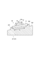
 図2は、図1の分光測定装置における積分球の一例を示す断面図である。図2に示すように、積分球20は、例えば取付ねじ等によって架台(不図示)に取り付けられており、その内壁には、高拡散反射物質が塗布されている。積分球20は、積分球本体200を備え、積分球本体200には、上述した入射開口部21、出射開口部22、及び試料導入開口部23が設けられている。 FIG. 2 is a cross-sectional view showing an example of an integrating sphere in the spectroscopic measurement apparatus of FIG. As shown in FIG. 2, the integrating sphere 20 is attached to a gantry (not shown) by, for example, an attaching screw or the like, and a highly diffuse reflective material is applied to the inner wall thereof. The integrating sphere 20 includes an integrating sphere main body 200, and the integrating sphere main body 200 is provided with the above-described entrance opening 21, exit opening 22, and sample introduction opening 23.
 入射開口部21は、励起光Lにおける照射光軸(以下、単に「照射光軸」という)の上流側である積分球本体200上側に設けられている。この入射開口部21には、入射用ライトガイド12(図1参照)を積分球本体200に接続する入射用ライトガイドホルダ210が挿入されて取り付けられている。 The incident opening 21 is provided on the upper side of the integrating sphere body 200, which is upstream of the irradiation optical axis (hereinafter simply referred to as “irradiation optical axis”) of the excitation light L. An incident light guide holder 210 for connecting the incident light guide 12 (see FIG. 1) to the integrating sphere body 200 is inserted and attached to the incident opening 21.
 入射用ライトガイドホルダ210は、出射用ライトガイド25を位置決めして保持するライトガイド保持部211を有している。また、入射用ライトガイドホルダ210には、コリメータレンズ212及びアパーチャ(光学部材)213が、照射光軸において上流から下流側にこの順で配設されている。コリメータレンズ212及びアパーチャ213は、試料1に励起光Lを入射させるための入射光学系を構成し、励起光Lが積分球20内で広がりながら伝播するように光学調整する。具体的には、コリメータレンズ212及びアパーチャ213は、図5に示すように、励起光Lの照射面積Sを試料1の被照射面積Sよりも大きくさせる所定広がり角で励起光Lを照射する。ここでは、試料1を内包するように当該試料1に励起光Lを照射する。 The incident light guide holder 210 has a light guide holding portion 211 that positions and holds the emission light guide 25. Further, the incident light guide holder 210 is provided with a collimator lens 212 and an aperture (optical member) 213 in this order from the upstream side to the downstream side on the irradiation optical axis. The collimator lens 212 and the aperture 213 constitute an incident optical system for causing the excitation light L to enter the sample 1 and optically adjust the excitation light L so as to propagate while spreading in the integrating sphere 20. Specifically, as shown in FIG. 5, the collimator lens 212 and the aperture 213 irradiate the excitation light L with a predetermined spread angle that makes the irradiation area S 2 of the excitation light L larger than the irradiated area S 1 of the sample 1. To do. Here, the sample 1 is irradiated with the excitation light L so as to contain the sample 1.
 なお、試料1の被照射面積Sは、試料1において励起光Lを受ける被照射領域Rの面積であり、励起光Lの照射面積Sは、試料1への入射位置における励起光Lの照射領域Rについての面積である。励起光Lの照射領域Rは、上方視において(励起光Lの照射方向から見て)矩形状(例えば、長方形)を有しており、試料1への入射位置における長軸方向長さが例えば8mm程度となるように設定されている。 The irradiated area S 1 of the sample 1 is the area of the irradiated region R 1 that receives the excitation light L in the sample 1, and the irradiated area S 2 of the excitation light L is the excitation light L at the incident position on the sample 1. is the area of the irradiation region R 2 of the. Irradiation region R 2 of the excitation light L, in the upper view (when viewed from the irradiation direction of the excitation light L) rectangular (e.g., rectangular) has a long axial length at the incident position of the sample 1 For example, it is set to be about 8 mm.
 図2に戻り、出射開口部22は、積分球本体200の中心位置を通り且つ照射光軸の垂直面上における所定位置に設けられている。出射開口部22には、出射用ライトガイド25を積分球本体200に接続するライトガイドホルダ220が挿入されて取り付けられている。 Referring back to FIG. 2, the exit opening 22 is provided at a predetermined position on the vertical plane of the irradiation optical axis that passes through the center position of the integrating sphere main body 200. A light guide holder 220 for connecting the light guide for emission 25 to the integrating sphere body 200 is inserted and attached to the emission opening 22.
 試料導入開口部23は、積分球本体200の下側に入射開口部21と対向するように設けられている。試料導入開口部23には、試料容器40を積分球20内に配置させる試料容器ホルダ24が、挿入されて着脱自在に取り付けられている。 The sample introduction opening 23 is provided on the lower side of the integrating sphere main body 200 so as to face the incident opening 21. A sample container holder 24 for placing the sample container 40 in the integrating sphere 20 is inserted into the sample introduction opening 23 and is detachably attached.
 また、積分球本体200の内壁面において試料導入開口部23と出射開口部22との間の所定位置には、積分球本体200の内部へ突出する遮光板205が設けられている。遮光板205は、試料1からの蛍光が出射用ライトガイド25に直接入射するのを防止する。 Further, a light shielding plate 205 that protrudes into the integrating sphere main body 200 is provided at a predetermined position between the sample introduction opening 23 and the emission opening 22 on the inner wall surface of the integrating sphere main body 200. The light shielding plate 205 prevents fluorescence from the sample 1 from directly entering the emission light guide 25.
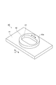
 図3は図1の分光測定装置における試料容器の一例を示す斜視図、図4は図1の分光測定装置における試料容器ホルダの一例を示す断面図、図5は図4の試料容器ホルダを載置面側から見た平面図である。図3に示すように、試料容器40は、積分球20を利用した量子収率測定等に用いられるものであって、矩形板状(例えば、長方形状)の鍔部(板部)41と、鍔部41上に設けられた凸部42と、凸部42に設けられ試料1を収容する凹部としての収容部43と、を有している。 3 is a perspective view showing an example of the sample container in the spectrometer of FIG. 1, FIG. 4 is a cross-sectional view showing an example of the sample container holder in the spectrometer of FIG. 1, and FIG. 5 shows the sample container holder of FIG. It is the top view seen from the installation surface side. As shown in FIG. 3, the sample container 40 is used for quantum yield measurement using the integrating sphere 20, and has a rectangular plate-like (for example, rectangular) collar (plate) 41; It has a convex part 42 provided on the flange part 41 and an accommodating part 43 as a concave part provided in the convex part 42 for accommodating the sample 1.
 なお、鍔部41の形状は、矩形状に限らず、円形形状や楕円形状など他の形状でもよい。このような試料容器40は、中心部分に貫通孔を有する円柱部材を板部材(板状部材)上に接着等により固定することで作製することができる。これにより、板部材のうち円柱部材が接着されていない部分が鍔部41となり、また、円柱部材の貫通穴が試料1を収容する凹部としての収容部43となる。このような製造方法によれば、比較的容易に試料容器40を製造することができる。 In addition, the shape of the collar part 41 is not limited to a rectangular shape, but may be other shapes such as a circular shape or an elliptical shape. Such a sample container 40 can be manufactured by fixing a columnar member having a through hole in the center portion on a plate member (plate-like member) by adhesion or the like. As a result, the portion of the plate member to which the cylindrical member is not bonded becomes the flange portion 41, and the through hole of the cylindrical member becomes the accommodating portion 43 as a concave portion for accommodating the sample 1. According to such a manufacturing method, the sample container 40 can be manufactured relatively easily.
 この試料容器40は、試料容器40による光の吸収を抑制する等のために好ましいとして、例えば石英や合成石英等の透明材料で形成されている。なお、試料容器40は、完全に透明されていなくともよい。凸部42は、上方から見て円形の外形を有しており、その断面が円形状となっている。収容部43は、上方から見て、鍔部41の長手方向に長尺状の長円形状(換言すると、鍔部41と同じ長軸を有するトラック形状)を有している。つまり、収容部43の開口による面(以下、収容部43の開口面43a)の長軸方向L1が鍔部41の長軸方向L2と同方向となる。また、収容部43の開口面43aの形状は長円形状に限らず、長方形状や楕円形状など、長軸を有する形状であればよい。収容部43の開口面43aの形状が長軸を有するため、開口面積を広くすることができる。この収容部43は、試料1に照射される励起光Lが試料1を内包するように試料1を収容する(図5参照)。 The sample container 40 is preferably made of a transparent material such as quartz or synthetic quartz, for example, for suppressing light absorption by the sample container 40. Note that the sample container 40 may not be completely transparent. The convex portion 42 has a circular outer shape when viewed from above, and has a circular cross section. The housing portion 43 has an elongated oval shape in the longitudinal direction of the flange portion 41 (in other words, a track shape having the same long axis as the flange portion 41) when viewed from above. That is, the major axis direction L1 of the surface (hereinafter referred to as the opening surface 43a of the accommodating portion 43) due to the opening of the accommodating portion 43 is the same as the major axis direction L2 of the flange portion 41. Moreover, the shape of the opening surface 43a of the accommodating part 43 is not restricted to an ellipse shape, What is necessary is just a shape which has a long axis, such as a rectangular shape and an ellipse shape. Since the shape of the opening surface 43a of the accommodating portion 43 has a long axis, the opening area can be increased. The accommodating portion 43 accommodates the sample 1 so that the excitation light L applied to the sample 1 includes the sample 1 (see FIG. 5).
 図4,5に示すように、試料容器ホルダ24は、試料容器40を積分球20内で保持するものである。試料容器ホルダ24の積分球20内に導入される部分は、積分球20の内壁と同じ高拡散反射物質が塗布されている。この試料容器ホルダ24は、載置台(傾斜部材)241を備え、載置台241は、試料容器40を載置する載置面242を有している。載置面242は、試料容器ホルダ24が試料導入開口部23に取り付けられた際に、照射光軸の垂直面(直交面)に対し傾斜するように形成されている。よって、試料容器ホルダ24を積分球20の試料導入開口部23に取り付けることにより、収容部43の開口面43aを照射光軸の直交面に対し傾斜させることができる。この載置面242において外周近傍部には、上方に突出する凸部としての位置決め部243が形成されている。 As shown in FIGS. 4 and 5, the sample container holder 24 holds the sample container 40 in the integrating sphere 20. The portion of the sample container holder 24 that is introduced into the integrating sphere 20 is coated with the same highly diffuse reflective material as the inner wall of the integrating sphere 20. The sample container holder 24 includes a mounting table (inclined member) 241, and the mounting table 241 has a mounting surface 242 on which the sample container 40 is mounted. The mounting surface 242 is formed to be inclined with respect to a vertical surface (orthogonal surface) of the irradiation optical axis when the sample container holder 24 is attached to the sample introduction opening 23. Therefore, by attaching the sample container holder 24 to the sample introduction opening 23 of the integrating sphere 20, the opening surface 43a of the housing portion 43 can be inclined with respect to the plane orthogonal to the irradiation optical axis. On the placement surface 242, a positioning portion 243 as a convex portion protruding upward is formed in the vicinity of the outer periphery.
 位置決め部243は、試料容器40の鍔部41の外形に対応する間隔で四箇所に配設されている。これら位置決め部243は、その内側上方の角部が切り欠かれたような角柱形状を有している。このような4つの位置決め部243の内側に入り込むように試料容器40を配置することで、試料容器40の鍔部41が各位置決め部243に係合し、これにより、試料容器40が載置台241上にて位置決めされて保持される。ここでの位置決め部243は、配置された試料容器40における収容部43の長軸方向と励起光Lの照射領域Rの長軸方向とが同方向となるように、試料容器40を位置決めする。また、このとき、載置台241の傾斜方向も配置された試料容器40における収容部43の長軸方向と同方向ように位置決めされるため、収容部43の傾斜方向と長軸方向が同方向となる。 The positioning portions 243 are arranged at four locations at intervals corresponding to the outer shape of the flange portion 41 of the sample container 40. These positioning portions 243 have a prismatic shape in which a corner portion on the inner upper side is cut out. By disposing the sample container 40 so as to enter the inside of the four positioning parts 243 as described above, the flange 41 of the sample container 40 is engaged with each positioning part 243, whereby the sample container 40 is placed on the mounting table 241. Positioned and held above. Positioning unit 243 here is the axial direction of the housing portion 43 in the arranged sample container 40 and the long axis direction of the irradiation region R 2 of the excitation light L so that the same direction, positioning the sample container 40 . At this time, since the tilt direction of the mounting table 241 is also positioned in the same direction as the major axis direction of the accommodating portion 43 in the sample container 40 arranged, the tilt direction and the major axis direction of the accommodating portion 43 are the same direction. Become.
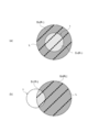
 図6は、アパーチャと収容部との関係を説明する図である。図6を用いて、上述したアパーチャ213の長軸方向及び収容部43の傾斜方向(収容部43の開口面43aの長軸方向)の関係と、その効果について説明する。図6(a),(c)に示すように、励起光Lは、アパーチャ213の開口により、長軸を有する形状(例えば、長方形状)に整形され、積分球20内を広がりながら伝播する。従って、励起光Lの照射光軸の直交面は、長軸を有する形状となり、アパーチャ213の長軸方向と照射光軸の直交面は同方向となる。これに対し、図6(b),(c)に示すように、載置台241の傾斜により、試料容器40の収容部43の開口面43aが、照射光軸の直交面に対し傾斜し、試料容器40の収容部43の開口面43aの傾斜方向と開口面43aの長軸方向が同方向となる(つまり、アパーチャ213の開口の長軸方向と収容部43の開口面43aの傾斜方向(または、長軸方向)は、角度を有して交わる)。従って、励起光Lの照射領域は、アパーチャ213で整形され形状よりもさらに縦長になるため、試料容器40の収容部43をより内包しやすくなる。 FIG. 6 is a diagram for explaining the relationship between the aperture and the accommodating portion. The relationship between the major axis direction of the aperture 213 and the inclination direction of the accommodating portion 43 (the major axis direction of the opening surface 43a of the accommodating portion 43) and the effects thereof will be described with reference to FIG. As shown in FIGS. 6A and 6C, the excitation light L is shaped into a shape having a long axis (for example, a rectangular shape) by the opening of the aperture 213 and propagates while spreading in the integrating sphere 20. Therefore, the orthogonal plane of the irradiation optical axis of the excitation light L has a shape having a long axis, and the long axis direction of the aperture 213 and the orthogonal plane of the irradiation optical axis are in the same direction. On the other hand, as shown in FIGS. 6B and 6C, due to the inclination of the mounting table 241, the opening surface 43a of the accommodating portion 43 of the sample container 40 is inclined with respect to the orthogonal plane of the irradiation optical axis, and the sample The inclination direction of the opening surface 43a of the container portion 43 of the container 40 and the major axis direction of the opening surface 43a are the same direction (that is, the major axis direction of the opening of the aperture 213 and the inclination direction of the opening surface 43a of the container portion 43 (or , Long axis direction) intersect with an angle). Accordingly, the irradiation region of the excitation light L is shaped by the aperture 213 and becomes longer than the shape, so that it becomes easier to enclose the accommodating portion 43 of the sample container 40.
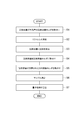
 次に、上記分光測定装置100Aによる分光測定方法について、図7のフローチャートを参照しつつ説明する。 Next, a spectroscopic measurement method using the spectroscopic measurement apparatus 100A will be described with reference to the flowchart of FIG.
 まず、試料容器40が未設置の(つまり、試料1がない状態の)試料容器ホルダ24を試料導入開口部23に取り付ける(S1)。なお、この状態では、当該試料容器ホルダ24は、積分球20の内壁の一部として機能する。そして、積分球20内に試料1を配置しない状態での分光測定であるリファレンス測定を行う(S2)。 First, the sample container holder 24 in which the sample container 40 is not installed (that is, the sample 1 is not present) is attached to the sample introduction opening 23 (S1). In this state, the sample container holder 24 functions as a part of the inner wall of the integrating sphere 20. Then, reference measurement, which is spectroscopic measurement in a state where the sample 1 is not arranged in the integrating sphere 20, is performed (S2).
 具体的には、励起光源11から光を出射させ、入射用ライトガイド12によって入射開口部21から積分球20内へ励起光Lを導光させる。そして、積分球20内部で多重拡散反射した被測定光を、出射ライトガイド125によって出射開口部22から分光分析装置30へ導光させ、当該分光分析装置30により波長スペクトル15a(図9(a)参照)を得る。この波長スペクトル15aは励起波長領域に強度を持つため、データ解析装置50により、励起波長領域の強度を積算して励起光領域強度Laを取得する。 Specifically, light is emitted from the excitation light source 11, and the excitation light L is guided from the incident opening 21 into the integrating sphere 20 by the incident light guide 12. Then, the light to be measured that has been diffusely reflected and reflected within the integrating sphere 20 is guided from the exit opening 22 to the spectroscopic analyzer 30 by the exit light guide 125, and the spectroscopic analyzer 30 causes the wavelength spectrum 15a (FIG. 9A). Browse). Since the wavelength spectrum 15a has an intensity in the excitation wavelength region, the data analyzer 50 integrates the excitation wavelength region intensity to obtain the excitation light region intensity La.
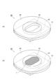
 次いで、試料容器40に試料1を収容する(S3)。すなわち、図8(a)に示すように、円環板状の収容補助カバー45を試料容器40に取り付ける。具体的には、収容補助カバー45において凸部42の断面外形に応じた形状の開口46に凸部42を挿入させて嵌め込みつつ、当該収容補助カバー45を鍔部41上に載置して鍔部41の上方側を覆う。なお、収容補助カバー45は、その厚さが凸部42と同程度又はそれより小さくなっている。また、収容補助カバー45は、試料1が黄色等の色調を有することが多いことから、試料1の位置を把握するために好ましいとして黒色を有している。 Next, the sample 1 is accommodated in the sample container 40 (S3). That is, as shown in FIG. 8A, the annular plate-shaped accommodation auxiliary cover 45 is attached to the sample container 40. Specifically, the accommodation auxiliary cover 45 is placed on the collar 41 while the projection 42 is inserted and fitted into the opening 46 having a shape corresponding to the cross-sectional outline of the projection 42 in the accommodation auxiliary cover 45. The upper side of the part 41 is covered. The accommodating auxiliary cover 45 has the same thickness as the convex portion 42 or smaller than that. Moreover, since the sample 1 often has a color tone such as yellow, the storage auxiliary cover 45 has a black color as preferable for grasping the position of the sample 1.
 なお、収容補助カバー45の形状は円環板状に限定されないが、開口46の形状は円形であるほうが好ましい。開口46に嵌め合わされる試料容器40の凸部42の外周形状を円形とすることで、ピンセットを用いた嵌合わせ等の取扱いが容易となる。 The shape of the storage auxiliary cover 45 is not limited to an annular plate shape, but the shape of the opening 46 is preferably circular. By making the outer peripheral shape of the convex portion 42 of the sample container 40 fitted into the opening 46 circular, handling such as fitting using tweezers becomes easy.
 続いて、図8(b)に示すように、収容補助カバー45を取り付けた状態で、試料容器40の収容部43に試料1を収容する。そして、金属ハケ等で試料1の表面をならして試料1の露出部分を平坦にした後、ピンセット等で収容補助カバー45を試料容器40から取り外す。試料1を平坦化する際には、余分な試料1について収容補助カバー45上に載せることにより、収容補助カバー45を取り外す際に一緒に除去できる。これにより、試料容器40の収容部43以外の部分に試料1が付着することを防ぐことができる。ちなみに、試料1が収容部43以外に付着した状態で試料容器40を積分球20内に配置すると、積分球20の内部が汚染され、測定精度が低下するおそれがある。 Subsequently, as shown in FIG. 8B, the sample 1 is accommodated in the accommodating portion 43 of the sample container 40 with the accommodating auxiliary cover 45 attached. Then, the surface of the sample 1 is leveled with a metal brush or the like to flatten the exposed portion of the sample 1, and then the storage auxiliary cover 45 is removed from the sample container 40 with tweezers or the like. When the sample 1 is flattened, the extra sample 1 is placed on the auxiliary storage cover 45 so that it can be removed when the auxiliary auxiliary cover 45 is removed. Thereby, it can prevent that the sample 1 adheres to parts other than the accommodating part 43 of the sample container 40. FIG. Incidentally, if the sample container 40 is placed in the integrating sphere 20 in a state where the sample 1 is adhered to other than the accommodating portion 43, the inside of the integrating sphere 20 may be contaminated and the measurement accuracy may be lowered.
 次いで、試料容器40の凸部42に試料カバー(不図示)を載置し、図4,5に示すように、試料容器40を試料容器ホルダ24の載置台241上に配置する(S4)。このとき、4つの位置決め部243内に試料容器40を配置し、これら位置決め部243に係止させる。これにより、試料容器ホルダ24上において、試料容器40が所定方向に方向付けされるように位置決めされて固定され、その結果、試料容器40の鍔部41の長軸方向と、収容部43の長軸方向と、励起光Lの照射領域Rの長軸方向と、載置台241の傾斜方向K1(収容部43の傾斜方向K2)とが、同方向となる。 Next, a sample cover (not shown) is placed on the convex portion 42 of the sample container 40, and the sample container 40 is placed on the placing table 241 of the sample container holder 24 as shown in FIGS. 4 and 5 (S4). At this time, the sample container 40 is disposed in the four positioning portions 243 and is locked to the positioning portions 243. As a result, the sample container 40 is positioned and fixed on the sample container holder 24 so that the sample container 40 is oriented in a predetermined direction. As a result, the long axis direction of the flange 41 of the sample container 40 and the length of the storage part 43 are fixed. the axial direction and the long axis direction of the irradiation region R 2 of the excitation light L, the inclination direction K1 of the table 241 (the inclination direction K2 of the housing portion 43), but the same direction.
 次いで、試料容器40が設置された試料容器ホルダ24を、試料導入開口部23に取り付ける(S5)。そして、積分球20内に試料1を配置した状態での分光測定であるサンプル測定を行う(S6)。 Next, the sample container holder 24 in which the sample container 40 is installed is attached to the sample introduction opening 23 (S5). And the sample measurement which is the spectroscopic measurement in the state which has arrange | positioned the sample 1 in the integrating sphere 20 is performed (S6).
 具体的には、励起光源11から光を出射させ、入射用ライトガイド12によって入射開口部21から積分球20内へ励起光Lを導光させ、これにより、励起光Lを試料容器ホルダ24上の試料1に照射する。このとき、励起光Lは、コリメータレンズを経て、アパーチャ213を通過することで、積分球20内で広がりながら矩形状で試料1に照射される。その結果、図5に示すように、励起光Lが試料1を内包するように照射される。 Specifically, light is emitted from the excitation light source 11, and the excitation light L is guided from the incident opening 21 into the integrating sphere 20 by the incident light guide 12, so that the excitation light L is transmitted onto the sample container holder 24. The sample 1 is irradiated. At this time, the excitation light L passes through the aperture 213 through the collimator lens, and is irradiated on the sample 1 in a rectangular shape while spreading in the integrating sphere 20. As a result, as shown in FIG. 5, the excitation light L is irradiated so as to enclose the sample 1.
 なお、アパーチャ213は、長軸を有する形状の開口を有することが好ましい。当該長軸を有する形状としては、楕円形状や長方形形状などが挙げられる。このとき、アパーチャ213の開口の長軸方向と励起光Lの照射光軸の直交面の長軸方向は同方向となる。従って、アパーチャ213の開口の長軸方向と試料容器40の収容部43の傾斜方向K2(長軸方向)は、角度を有して交わる。 The aperture 213 preferably has an opening having a shape having a long axis. Examples of the shape having the long axis include an elliptical shape and a rectangular shape. At this time, the major axis direction of the opening of the aperture 213 and the major axis direction of the plane orthogonal to the irradiation optical axis of the excitation light L are the same direction. Therefore, the major axis direction of the opening of the aperture 213 and the inclination direction K2 (major axis direction) of the accommodating portion 43 of the sample container 40 intersect with each other with an angle.
 続いて、積分球20内部で多重拡散反射した被測定光を、出射ライトガイド125によって出射開口部22から分光分析装置30へ導光させ、当該分光分析装置30により波長スペクトル15b(図9(b)参照)を得る。ここでの被測定光としては、励起光Lの照射により試料1で生じた蛍光等の発光、及び励起光Lのうち試料1で散乱、反射等された光成分を含んでいる。 Subsequently, the light to be measured that has been diffusely reflected and reflected within the integrating sphere 20 is guided to the spectroscopic analysis device 30 from the output opening 22 by the output light guide 125, and the spectral spectrum 30b (FIG. 9B). ) See). The light to be measured here includes light emission such as fluorescence generated in the sample 1 by the irradiation of the excitation light L, and light components scattered and reflected by the sample 1 in the excitation light L.
 そして、データ解析装置50により、波長スペクトル15bにおける励起波長領域の強度を積算して励起光領域強度Lbを取得すると共に、蛍光波長領域の強度を積算して蛍光領域強度Lcを取得する。なお、励起光領域強度Lbは、試料1によって励起光Lが吸収される分その強度が減少するものとなり、蛍光領域強度Lcは、試料1から発生した蛍光量となる。 Then, the data analyzer 50 integrates the excitation wavelength region intensity in the wavelength spectrum 15b to obtain the excitation light region intensity Lb, and also integrates the fluorescence wavelength region intensity to obtain the fluorescence region intensity Lc. The excitation light region intensity Lb decreases as the excitation light L is absorbed by the sample 1, and the fluorescence region intensity Lc is the amount of fluorescence generated from the sample 1.
 次いで、取得した強度La,Lb,Lcに基づいて、データ解析装置50により量子収率を算出する(S7)。量子収率は、試料1が発した光のフォトン数と試料1に吸収された励起光Lのフォトン数との比で表されることから、「試料1の外部量子効率(試料1から発生した蛍光量)」/「試料1の光吸収率(試料1に吸収された励起光量)」で求めることができる。よって、上記S7では、例えば、励起光領域強度La,Lbの差分に基づいて光吸収率を算出し、蛍光領域強度Lcに関する外部量子効率を当該光吸収率で除算することにより、量子収率を求める。最後に、解析結果を表示装置62に表示させ、測定を終了する。 Next, the quantum yield is calculated by the data analysis device 50 based on the acquired intensities La, Lb, and Lc (S7). The quantum yield is expressed by the ratio between the number of photons emitted from the sample 1 and the number of photons of the excitation light L absorbed by the sample 1, so that “the external quantum efficiency of the sample 1 (generated from the sample 1 (Fluorescence amount) "/" light absorption rate of sample 1 (excitation light amount absorbed by sample 1) ". Therefore, in S7, for example, the light absorption rate is calculated based on the difference between the excitation light region intensities La and Lb, and the external quantum efficiency related to the fluorescence region intensity Lc is divided by the light absorption rate, thereby obtaining the quantum yield. Ask. Finally, the analysis result is displayed on the display device 62, and the measurement is terminated.
 ここで、本実施形態における上記演算では、波長スペクトル15a,15bに対し、分光測定装置100A全体での測定特性や検出感度等についての装置補正を行うことができる。装置補正に用いられる装置補正係数は、例えば、予め求めてデータ解析装置50に記憶させることができる。これにより、分光測定装置100A自身の影響を、試料1の分光測定に好適に考慮することが可能となる。 Here, in the above-described calculation in the present embodiment, it is possible to perform device correction for the measurement characteristics, detection sensitivity, and the like of the entire spectroscopic measurement device 100A with respect to the wavelength spectra 15a and 15b. The device correction coefficient used for the device correction can be obtained in advance and stored in the data analysis device 50, for example. Thereby, the influence of the spectroscopic measurement apparatus 100 </ b> A itself can be suitably taken into consideration for the spectroscopic measurement of the sample 1.
 また、本実施形態における上記演算では、波長スペクトル15a,15bに対し、試料容器40による光の吸収に関する容器補正を行うことができる。容器補正に用いられる容器補正係数は、例えば、試料1の分光測定(上記S2,S6)とは別に、白色光を用いてリファレンス測定及びサンプル測定を行うことにより算出できる。これにより、試料容器40による光の吸収の影響を、試料1の分光測定に好適に考慮することが可能となる。 Further, in the above calculation in the present embodiment, the container correction relating to the light absorption by the sample container 40 can be performed on the wavelength spectra 15a and 15b. The container correction coefficient used for container correction can be calculated, for example, by performing reference measurement and sample measurement using white light separately from the spectroscopic measurement of sample 1 (S2 and S6 above). As a result, the influence of light absorption by the sample container 40 can be suitably taken into account for the spectroscopic measurement of the sample 1.
 ところで、試料1が励起されると、全方位に蛍光が放射され、また、多くの試料1は、蛍光波長の光も吸収波長領域とすることから、試料1が発した蛍光を試料1自身で吸収する自己吸収を起こす。そのため、当該自己吸収によって量子収率が小さく見積もられてしまうことが懸念される。 By the way, when the sample 1 is excited, fluorescence is emitted in all directions, and many of the samples 1 also make the light of the fluorescence wavelength be in the absorption wavelength region. Causes self-absorption to absorb. Therefore, there is a concern that the quantum yield is estimated to be small due to the self-absorption.
 この点、本実施形態では、次の理由から、自己吸収量を減少させることができ、量子収率を精度よく求めることが可能となる。すなわち、試料1の一部に励起光Lが照射される場合には、試料1において被照射領域と照射されない領域との境界面積が広い分、自己吸収量が多いのに対し、本実施形態では、励起光Lが試料1全体を内包するように照射されることから、試料1において被照射領域と照射されない領域との境界面積が狭くなり、自己吸収量が小さくなるためである。 In this respect, in the present embodiment, the self-absorption amount can be reduced and the quantum yield can be accurately obtained for the following reason. That is, when a part of the sample 1 is irradiated with the excitation light L, the amount of self-absorption is large because the boundary area between the irradiated region and the non-irradiated region in the sample 1 is large. Because the excitation light L is irradiated so as to include the entire sample 1, the boundary area between the irradiated region and the non-irradiated region in the sample 1 becomes narrow, and the self-absorption amount becomes small.
 また、例えば試料1を収容する試料容器として一般的なシャーレを用いる場合、要される試料1の量が多くなり、且つ、試料1の一部に励起光Lが照射されるために自己吸収量も多くなるという傾向がある。これに対し、本実施形態の試料容器40では、少量の試料1を収容でき、且つ、試料1全体を包むように励起光Lを照射させることができるために、試料1の量が少なくても量子収率を精度よく測定することが可能となる。つまり、本実施形態は、積分球20を用いた量子収率測定において、少量サンプルに対しても測定可能となるものである。 For example, when a general petri dish is used as a sample container for storing the sample 1, the amount of the sample 1 required increases, and a part of the sample 1 is irradiated with the excitation light L. There is a tendency to increase. On the other hand, in the sample container 40 of the present embodiment, a small amount of the sample 1 can be accommodated and the excitation light L can be irradiated so as to wrap the entire sample 1. The yield can be accurately measured. That is, this embodiment can measure even a small amount of sample in the quantum yield measurement using the integrating sphere 20.
 また、一般的なシャーレを用いる場合には、収容する試料1の量がユーザーによって区々となり易いが、本実施形態の試料容器40を用いると、試料1の量を定量にでき、よって、異なる試料1の測定データを比較し易くできる。ちなみに、少ない試料1で測定する場合には、収容部43の深さを浅くすることも考えられるが、この場合、試料容器40に比べ、試料1が離散しやすくなるため、少なくとも使い勝手の点で実用的ではない。 In addition, when a general petri dish is used, the amount of the sample 1 to be stored tends to vary depending on the user. However, if the sample container 40 of the present embodiment is used, the amount of the sample 1 can be quantified, and thus differs. The measurement data of the sample 1 can be easily compared. Incidentally, in the case of measuring with a small number of samples 1, it is conceivable to reduce the depth of the accommodating portion 43. In this case, however, the sample 1 is more easily separated than the sample container 40, so at least in terms of ease of use. Not practical.
 なお、通常、量子収率測定における演算では、試料1の面積よりも励起光Lの照射面積Sが小さいことを前提としており、試料1面積が励起光Lの照射面積Sよりも小さい場合を想定していない。しかし、上述したように、量子収率は相対値で算出されることから、試料1面積及び照射面積Sの影響をキャンセルできるため、かかる前提においても、本実施形態では、量子収率を精度よく求めることができるといえる。 Normally, in the calculation in quantum yield measurements, than the area of the sample 1 is based on the assumption that the irradiation area S 2 is smaller excitation light L, when the sample 1 having a smaller area than the irradiation area S 2 of the excitation light L Is not assumed. However, as described above, since the quantum yield is calculated as a relative value, it is possible to cancel the effect of the sample 1 area and irradiation area S 2, even in such a premise, in the present embodiment, accuracy quantum yield It can be said that it can be asked well.
 また、本実施形態では、上述したように、試料容器40が照射光軸の垂直面に対し傾斜するように構成されている。これにより、入射開口部21から積分球20内に入射した励起光Lが、試料1で反射し入射開口部21から出射するのを抑制することができる。その結果、試料1からの被測定光や試料1で反射した励起光Lを、積分球20内で積極的に多重反射させることができ、より正確に量子収率を測定可能となる。 In the present embodiment, as described above, the sample container 40 is configured to be inclined with respect to the vertical plane of the irradiation optical axis. Thereby, it is possible to suppress the excitation light L that has entered the integrating sphere 20 from the incident opening 21 from being reflected by the sample 1 and emitted from the incident opening 21. As a result, the light to be measured from the sample 1 and the excitation light L reflected by the sample 1 can be actively multiple-reflected in the integrating sphere 20, and the quantum yield can be measured more accurately.
 また、本実施形態では、上述したように、試料1を収容部43に収容する際、収容補助カバー45により、鍔部41に試料1が付着するのを防止でき、積分球20の内壁や試料容器ホルダ24に塗布された高拡散反射物質に試料1が付着するのを抑制できる。また、試料容器40の収容部43の長軸が鍔部41の長軸と同方向とされていることから、試料容器40を取り付けた際、収容部43の方向を一義的に決めることができる。 In the present embodiment, as described above, when the sample 1 is accommodated in the accommodating portion 43, the accommodation auxiliary cover 45 can prevent the sample 1 from adhering to the flange portion 41, and the inner wall of the integrating sphere 20 and the sample can be prevented. It is possible to suppress the sample 1 from adhering to the highly diffuse reflection material applied to the container holder 24. Moreover, since the major axis of the accommodating part 43 of the sample container 40 is set in the same direction as the major axis of the flange 41, the direction of the accommodating part 43 can be uniquely determined when the sample container 40 is attached. .
 また、本実施形態において積分球本体200の出射開口部22の位置は、特に限定されるものではなく、例えば試料1からの被測定光が直接入射しない位置であれば、何れの位置でもよい。 In the present embodiment, the position of the exit opening 22 of the integrating sphere body 200 is not particularly limited, and may be any position as long as the light to be measured from the sample 1 is not directly incident.
 ちなみに、本実施形態では、励起光Lが試料1を内包するように、光出射部7からの励起光Lを広げるレンズをさらに設けてもよい。また、コリメータレンズ212及びアパーチャ213を入射光学系として備えているが、これら何れか一方のみを備えていてもよい。さらにまた、広がった励起光Lが入射用ライトガイド12から出射されることから、入射光学系を入射用ライトガイド12の出射端部を含んで(又はのみで)構成してもよい。 Incidentally, in this embodiment, a lens that spreads the excitation light L from the light emitting section 7 may be further provided so that the excitation light L includes the sample 1. Further, although the collimator lens 212 and the aperture 213 are provided as the incident optical system, only one of them may be provided. Furthermore, since the spread excitation light L is emitted from the incident light guide 12, the incident optical system may be configured to include (or only) the emission end portion of the incident light guide 12.
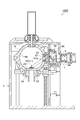
 図11は、変形例に係る分光測定装置を示す断面図である。図11に示すように、変形例に係る分光測定装置100Bは、試料1に対して斜めから励起光Lを照射可能な構成を有している。このような分光測定装置100Bは、暗箱5を備えている。 FIG. 11 is a cross-sectional view showing a spectroscopic measurement apparatus according to a modification. As shown in FIG. 11, the spectroscopic measurement apparatus 100 </ b> B according to the modification has a configuration that can irradiate the sample 1 with the excitation light L from an oblique direction. Such a spectroscopic measurement apparatus 100 </ b> B includes a dark box 5.
 暗箱5は、金属からなる直方体状の箱体であって、外部からの光の侵入を遮断する。暗箱5の内面5aには、励起光L及び被測定光を吸収する材料による塗装等が施されている。この暗箱5内には、積分球14が配置されている。積分球14は、その内面14aに硫酸バリウム等の高拡散反射剤の塗布が施されるか、若しくはPTFEやスペクトラロン等の材料で形成されている。この積分球14には、出射開口部を介して光検出部(不図示,光検出器)が接続されている。 The dark box 5 is a rectangular parallelepiped box made of metal and blocks light from entering from the outside. The inner surface 5a of the dark box 5 is coated with a material that absorbs the excitation light L and the light to be measured. An integrating sphere 14 is disposed in the dark box 5. The integrating sphere 14 is coated with a highly diffuse reflector such as barium sulfate on the inner surface 14a, or is formed of a material such as PTFE or Spectralon. The integrating sphere 14 is connected to a light detector (not shown, a light detector) through an emission opening.
 また、暗箱5の一方の側壁には、光発生部(不図示)の光出射部7が接続されている。光発生部は、例えばキセノンランプや分光器等により構成された励起光源であって、励起光Lを発生させる。励起光Lは、光出射部7に設けられたレンズ8によってコリメートされて、暗箱5内に入射する。 Further, a light emitting part 7 of a light generating part (not shown) is connected to one side wall of the dark box 5. The light generation unit is an excitation light source configured by, for example, a xenon lamp or a spectroscope, and generates the excitation light L. The excitation light L is collimated by the lens 8 provided in the light emitting unit 7 and enters the dark box 5.
 また、暗箱5内においてレンズ8と積分球14との間には、コリメータレンズ64、ミラー65,66が、照射光軸において上流から下流側にこの順で配設されている。積分球14の入射開口部21には、アパーチャ67が設けられている。アパーチャ67は、長軸を有する形状の開口部を有しており、アパーチャ67の開口部の少なくとも一部には、切欠き67aが形成されている。切欠き67aの形状は、アパーチャ67を通過し試料1に入射される励起光Lが試料1の領域(上方視における試料1の面積)よりも広くなるように形成されている。 In the dark box 5, between the lens 8 and the integrating sphere 14, a collimator lens 64 and mirrors 65 and 66 are arranged in this order from upstream to downstream in the irradiation optical axis. An aperture 67 is provided in the incident aperture 21 of the integrating sphere 14. The aperture 67 has an opening having a shape having a long axis, and a notch 67 a is formed in at least a part of the opening of the aperture 67. The shape of the notch 67a is formed so that the excitation light L that passes through the aperture 67 and enters the sample 1 is wider than the region of the sample 1 (the area of the sample 1 when viewed from above).
 これらコリメータレンズ64、ミラー65,66及びアパーチャ67は、試料1に励起光Lを入射させるための入射光学系を構成する。この入射光学系においては、暗箱5に入射した励起光Lは、コリメータレンズ64で平行化され、ミラー65、66で順次反射され、アパーチャ67を通過して積分球14に入射され、これにより、励起光Lは、積分球14内において試料1を内包するように試料容器40へ照射される。ミラー66は、励起光Lの照射光軸の直交面(垂直面)が、試料容器40の収容部43の開口面43aに対し、傾斜するように、励起光Lの照射光軸の入射角度を調整する光学部材である。これにより、励起光Lの照射光軸の直交面に対する収容部43の開口面43aの傾斜方向と、収容部43の開口面43aの長軸方向L1(図3参照)が同方向となる。 The collimator lens 64, the mirrors 65 and 66, and the aperture 67 constitute an incident optical system for causing the excitation light L to enter the sample 1. In this incident optical system, the excitation light L incident on the dark box 5 is collimated by the collimator lens 64, is sequentially reflected by the mirrors 65 and 66, passes through the aperture 67, and is incident on the integrating sphere 14. The excitation light L is applied to the sample container 40 so as to enclose the sample 1 in the integrating sphere 14. The mirror 66 changes the incident angle of the irradiation light axis of the excitation light L so that the orthogonal surface (vertical surface) of the irradiation light axis of the excitation light L is inclined with respect to the opening surface 43a of the accommodating portion 43 of the sample container 40. An optical member to be adjusted. Thereby, the inclination direction of the opening surface 43a of the accommodating part 43 with respect to the orthogonal plane of the irradiation light axis of the excitation light L and the major axis direction L1 (see FIG. 3) of the opening surface 43a of the accommodating part 43 are the same direction.
 なお、変形例に係る分光測定装置100Bでは、励起光Lが試料1を内包するように、光出射部7からの励起光Lを広げるレンズを設けてもよい。また、コリメータレンズ64、ミラー65,66及びアパーチャ67を入射光学系として備えているが、アパーチャ67のみ備えていてもよい。さらにまた、広がった励起光Lが光出射部7から出射されることから、入射光学系を光出射部7の出射端部を含んで(又はのみで)構成してもよい。 In the spectroscopic measurement apparatus 100B according to the modification, a lens that spreads the excitation light L from the light emitting unit 7 may be provided so that the excitation light L includes the sample 1. Further, although the collimator lens 64, the mirrors 65 and 66, and the aperture 67 are provided as the incident optical system, only the aperture 67 may be provided. Furthermore, since the spread excitation light L is emitted from the light emitting part 7, the incident optical system may be configured including (or only) the emission end part of the light emitting part 7.
 以上、好適な実施形態について説明したが、本発明は、上記実施形態に限られるものではなく、各請求項に記載した要旨を変更しない範囲で変形し、又は他のものに適用してもよい。 As mentioned above, although preferred embodiment was described, this invention is not restricted to the said embodiment, You may change in the range which does not change the summary described in each claim, or may apply to another thing. .
 例えば、また、上記実施形態では、積分器として積分球14を用いたが、その内部の光を空間的に積分する手段(光学コンポーネント)であればよく、例えば特開2009-103654号公報に開示された積分半球を用いてもよい。また、上記実施形態では、励起光Lが試料1を内包するように構成すればよく、例えば、励起光Lの入射光学系、及び、試料容器40の収容部43の形状の少なくとも一方を調整することにより、励起光Lが試料1を内包するようにしてもよい。 For example, in the above embodiment, the integrating sphere 14 is used as an integrator, but any means (optical component) for spatially integrating the light inside the integrating sphere 14 may be used. For example, it is disclosed in Japanese Patent Application Laid-Open No. 2009-103654. An integrated hemisphere may be used. In the above embodiment, the excitation light L may be configured to include the sample 1. For example, at least one of the incident optical system of the excitation light L and the shape of the housing portion 43 of the sample container 40 is adjusted. Thus, the excitation light L may include the sample 1.
 また、上記実施形態では、積分器に取り付けられる試料ホルダである試料容器ホルダ24が収容部43を有する試料容器40を保持したが、収容部43を有する試料容器ホルダ24を積分器に取り付けてもよい。 Moreover, in the said embodiment, although the sample container holder 24 which is a sample holder attached to an integrator hold | maintained the sample container 40 which has the accommodating part 43, even if the sample container holder 24 which has the accommodating part 43 is attached to an integrator, Good.
 また、上記実施形態では、分光測定装置および分光測定方法の対象として、主に量子収率(効率)測定を挙げたが、これに限らず、反射率測定や透過率測定等を対象としてもよい。 Moreover, in the said embodiment, although the quantum yield (efficiency) measurement was mainly mentioned as an object of a spectrometer and a spectroscopy measurement method, it is not restricted to this, It is good also considering a reflectance measurement, a transmittance | permeability measurement, etc. .
 本発明の一側面によれば、量子収率を精度よく求めることが可能となる。 According to one aspect of the present invention, the quantum yield can be obtained with high accuracy.
 1…試料、11…励起光源(光源)、14,20…積分器、21…入射開口部、22…出射開口部、23…試料導入開口部、24…試料容器ホルダ(試料ホルダ)、31b…光検出器、40…試料容器、41…板部(鍔部)、42…凸部、43…収容部、43a…開口面、50…データ解析装置(解析手段)、64…コリメータレンズ(入射光学系)、65,66…ミラー(入射光学系)、67…アパーチャ(入射光学系)、100A,100B…分光測定装置、212…コリメータレンズ(入射光学系)、213…アパーチャ(入射光学系,光学部材)、241…載置台(傾斜部材)、L…励起光。 DESCRIPTION OF SYMBOLS 1 ... Sample, 11 ... Excitation light source (light source), 14, 20 ... Integrator, 21 ... Incident opening part, 22 ... Outlet opening part, 23 ... Sample introduction opening part, 24 ... Sample container holder (sample holder), 31b ... Photodetector 40 ... Sample container 41 ... Plate part (saddle part) 42 ... Convex part 43 ... Accommodating part 43a ... Open surface 50 ... Data analysis device (analysis means) 64 ... Collimator lens (incident optics) System), 65, 66 ... Mirror (incident optical system), 67 ... Aperture (incident optical system), 100A, 100B ... Spectrometer, 212 ... Collimator lens (incident optical system), 213 ... Aperture (incident optical system, optical) Member), 241... Mounting table (inclined member), L... Excitation light.

Claims (14)

  1.  測定対象となる試料に励起光を照射し、被測定光を検出する分光測定装置であって、
     前記励起光を発生させる光源と、
     前記励起光が入射される入射開口部と、前記被測定光を出射する出射開口部とを有する積分器と、
     前記積分器内に配置され、前記試料を収容する収容部と、
     前記試料に前記励起光を入射させる入射光学系と、
     前記出射開口部から出射された前記被測定光を検出する光検出器と、
     前記光検出器で検出された検出値に基づき前記試料の量子収率を算出する解析手段と、を備え、
     前記励起光は、前記試料を内包するように当該試料に照射される、分光測定装置。
    A spectrometer for irradiating a sample to be measured with excitation light and detecting light to be measured,
    A light source for generating the excitation light;
    An integrator having an incident opening through which the excitation light is incident and an output opening through which the measured light is emitted;
    A storage unit disposed in the integrator for storing the sample;
    An incident optical system for causing the excitation light to enter the sample;
    A photodetector for detecting the light to be measured emitted from the exit opening;
    Analyzing means for calculating a quantum yield of the sample based on a detection value detected by the photodetector;
    The spectrometer is irradiated with the excitation light so as to enclose the sample.
  2.  前記入射光学系は、前記励起光が前記試料を内包するように前記励起光を調整する、請求項1に記載の分光測定装置。 The spectrometer according to claim 1, wherein the incident optical system adjusts the excitation light so that the excitation light includes the sample.
  3.  前記収容部は、前記励起光が前記試料を内包するように前記試料を収容する、請求項1又は2に記載の分光測定装置。 The spectroscopic measurement apparatus according to claim 1, wherein the storage unit stores the sample such that the excitation light includes the sample.
  4.  前記積分器は、前記収容部を前記積分器内に配置するための試料ホルダが取り付けられる試料導入開口部を有し、
     前記試料ホルダは、前記励起光における照射光軸の直交面に対し前記収容部の開口面が傾斜するように前記試料導入開口部に取り付けられる、請求項1~3の何れか一項に記載の分光測定装置。
    The integrator has a sample introduction opening to which a sample holder for arranging the accommodating portion in the integrator is attached,
    4. The sample holder according to claim 1, wherein the sample holder is attached to the sample introduction opening so that an opening surface of the housing portion is inclined with respect to a plane orthogonal to an irradiation optical axis in the excitation light. Spectrometer.
  5.  前記収容部の前記開口面の傾斜方向と前記収容部の開口面の長軸方向とは、互いに同方向である、請求項4に記載の分光測定装置。 The spectroscopic measurement device according to claim 4, wherein an inclination direction of the opening surface of the housing portion and a major axis direction of the opening surface of the housing portion are in the same direction.
  6.  前記入射光学系は、長軸を有する形状の開口を有する光学部材を備え、
     前記光学部材の開口の長軸方向と前記収容部の開口面の傾斜方向とは、角度を有する、請求項4又は5に記載の分光測定装置。
    The incident optical system includes an optical member having an opening having a shape having a long axis,
    The spectroscopic measurement device according to claim 4 or 5, wherein a major axis direction of the opening of the optical member and an inclination direction of the opening surface of the housing portion have an angle.
  7.  前記試料ホルダは、
     前記収容部を含む試料容器を載置するための載置面を有し、
     前記励起光における照射光軸の直交面に対し前記載置面が傾斜するように、前記試料導入開口部に取り付けられる、請求項4~6の何れか一項に記載の分光測定装置。
    The sample holder is
    Having a mounting surface for mounting the sample container including the container;
    The spectroscopic measurement apparatus according to any one of claims 4 to 6, wherein the spectroscopic measurement apparatus is attached to the sample introduction opening so that the mounting surface is inclined with respect to a plane orthogonal to an irradiation optical axis of the excitation light.
  8.  前記試料ホルダは、前記載置面を有する傾斜部材を備える、請求項7に記載の分光測定装置。 The spectroscopic measurement apparatus according to claim 7, wherein the sample holder includes an inclined member having the mounting surface.
  9.  前記入射光学系は、前記収容部の開口面に対する照射光軸の角度を調整する光学部材を有する、請求項4又は5に記載の分光測定装置。 The spectroscopic measurement apparatus according to claim 4 or 5, wherein the incident optical system includes an optical member that adjusts an angle of an irradiation optical axis with respect to an opening surface of the housing portion.
  10.  測定対象となる試料に励起光を照射し、被測定光を検出する分光測定方法であって、
     積分器内に前記試料を配置する工程と、
     前記励起光が前記試料を内包するように、前記積分器内へ前記励起光を照射して前記試料に入射させる工程と、
     前記積分器から出射された前記被測定光を検出する工程と、
     検出された前記被測定光に基づき前記試料の量子収率を算出する工程と、を含む、分光測定方法。
    A spectroscopic measurement method for detecting excitation light by irradiating a sample to be measured with excitation light,
    Placing the sample in an integrator;
    Irradiating the excitation light into the integrator and making it enter the sample so that the excitation light includes the sample;
    Detecting the light to be measured emitted from the integrator;
    And a step of calculating a quantum yield of the sample based on the detected light to be measured.
  11.  積分器を利用した量子収率測定に用いられる試料容器であって、
     矩形板状の板部と、
     前記板部上に設けられた凸部と、
     前記凸部に設けられ、測定対象となる試料を収容する収容部と、を備え、
     前記収容部は、前記試料に照射される励起光が前記試料を内包するように、前記試料を収容する、試料容器。
    A sample container used for quantum yield measurement using an integrator,
    A rectangular plate-shaped plate portion;
    A convex portion provided on the plate portion;
    A housing part that is provided on the convex part and houses a sample to be measured;
    The container is a sample container that houses the sample such that excitation light applied to the sample includes the sample.
  12.  前記凸部の断面は、円形状である、請求項11に記載の試料容器。 The sample container according to claim 11, wherein a cross section of the convex portion is circular.
  13.  前記収容部の開口は、長軸を有する形状である、請求項11に記載の試料容器。 The sample container according to claim 11, wherein the opening of the accommodating portion has a shape having a long axis.
  14.  貫通孔を有する円柱部材を、板状部材の面上に固定されることで形成される前記試料容器であって、
     前記板部が前記板状部材で構成され、前記凸部が前記円柱部材で構成され、前記収容部が前記貫通孔で構成される、請求項11~13の何れか一項に記載の試料容器。
    The sample container formed by fixing a cylindrical member having a through hole on the surface of a plate-shaped member,
    The sample container according to any one of claims 11 to 13, wherein the plate portion is constituted by the plate-like member, the convex portion is constituted by the cylindrical member, and the accommodating portion is constituted by the through-hole. .
PCT/JP2013/075033 2013-02-04 2013-09-17 Spectrum measuring device, spectrum measuring method, and specimen container WO2014119038A1 (en)

Priority Applications (5)

Application Number Priority Date Filing Date Title
KR1020157016500A KR20150090149A (en) 2013-02-04 2013-09-17 Spectrum measuring device, spectrum measuring method, and specimen container
CN201380072255.2A CN104969061B (en) 2013-02-04 2013-09-17 Spectroscopic measurement device, spectral photometry method and sample container
KR1020187007646A KR20180031809A (en) 2013-02-04 2013-09-17 Spectrum measuring device, spectrum measuring method, and specimen container
US14/764,703 US10209189B2 (en) 2013-02-04 2013-09-17 Spectrum measuring device, spectrum measuring method, and specimen container
EP13873636.8A EP2952881B1 (en) 2013-02-04 2013-09-17 Spectrum measuring device, spectrum measuring method, and specimen container

Applications Claiming Priority (2)

Application Number Priority Date Filing Date Title
JP2013019409A JP5529305B1 (en) 2013-02-04 2013-02-04 Spectrometer and spectroscopic method
JP2013-019409 2013-02-04

Publications (1)

Publication Number Publication Date
WO2014119038A1 true WO2014119038A1 (en) 2014-08-07

Family

ID=51175795

Family Applications (1)

Application Number Title Priority Date Filing Date
PCT/JP2013/075033 WO2014119038A1 (en) 2013-02-04 2013-09-17 Spectrum measuring device, spectrum measuring method, and specimen container

Country Status (7)

Country Link
US (1) US10209189B2 (en)
EP (1) EP2952881B1 (en)
JP (1) JP5529305B1 (en)
KR (2) KR20150090149A (en)
CN (1) CN104969061B (en)
TW (1) TWI613434B (en)
WO (1) WO2014119038A1 (en)

Cited By (1)

* Cited by examiner, † Cited by third party
Publication number Priority date Publication date Assignee Title
WO2016088574A1 (en) * 2014-12-02 2016-06-09 浜松ホトニクス株式会社 Spectrometry device and spectrometry method

Families Citing this family (16)

* Cited by examiner, † Cited by third party
Publication number Priority date Publication date Assignee Title
JP5944843B2 (en) * 2013-02-04 2016-07-05 浜松ホトニクス株式会社 Spectrometer and spectroscopic method
CN109341857A (en) * 2014-12-02 2019-02-15 浜松光子学株式会社 Spectroscopic measurement device and spectral photometry method
KR101802462B1 (en) * 2016-04-21 2017-11-28 서울대학교산학협력단 Apparatus for testing
JP6227067B1 (en) 2016-07-25 2017-11-08 浜松ホトニクス株式会社 Optical measuring device
JP6227068B1 (en) * 2016-07-27 2017-11-08 浜松ホトニクス株式会社 Sample container holding member, optical measurement device, and sample container arrangement method
JP6943618B2 (en) * 2017-05-17 2021-10-06 浜松ホトニクス株式会社 Spectral measuring device and spectroscopic measuring method
JP6920887B2 (en) * 2017-06-02 2021-08-18 浜松ホトニクス株式会社 Optical measuring device and optical measuring method
RU2753446C1 (en) * 2018-03-14 2021-08-16 Грейнсенс Ой Sample containers for use inside integration chambers and corresponding devices
CN108827918B (en) * 2018-05-29 2024-07-26 天津九光科技发展有限责任公司 Diffuse reflection spectrum measuring device, measuring method and correcting method based on integrating sphere
JP6492220B1 (en) * 2018-09-26 2019-03-27 大塚電子株式会社 Measurement system and method
CN109612969B (en) * 2018-12-12 2021-07-27 闽江学院 Photochromic measuring device and testing method for long-afterglow illuminant
JP6763995B2 (en) * 2019-04-18 2020-09-30 浜松ホトニクス株式会社 Spectral measuring device and spectroscopic measuring method
CN110056842B (en) * 2019-06-06 2021-01-05 中国科学院长春光学精密机械与物理研究所 Single star simulator and light source thereof
CN112665826A (en) * 2019-10-15 2021-04-16 成都辰显光电有限公司 Integrating sphere detector
JP6751214B1 (en) 2020-02-12 2020-09-02 デクセリアルズ株式会社 Measuring device and film forming device
CN113607663B (en) * 2021-07-06 2024-07-23 武汉理工大学 Diffuse reflection type multipurpose multivariable coupling in-situ optical absorption testing device and method

Citations (9)

* Cited by examiner, † Cited by third party
Publication number Priority date Publication date Assignee Title
US4583860A (en) * 1983-11-30 1986-04-22 The United States Of America As Represented By The Administrator Of The National Aeronautics And Space Administration Optical multiple sample vacuum integrating sphere
JPH068526Y2 (en) * 1987-12-14 1994-03-02 通商産業省工業技術院長 Preparation for powder sample
JP2003215041A (en) 2002-01-24 2003-07-30 National Institute Of Advanced Industrial & Technology Method and apparatus for measurement of absolute fluorescence quantum efficiency of solid sample
JP2004309323A (en) * 2003-04-08 2004-11-04 Oputeru:Kk Method and system for measuring absolute quantum efficiency of light-emitting device
JP2007086031A (en) * 2005-09-26 2007-04-05 Hamamatsu Photonics Kk Photodetection device and implement for sample holder
JP2009103654A (en) 2007-10-25 2009-05-14 Otsuka Denshi Co Ltd Integrating photometer and measuring method
JP3165429U (en) * 2010-11-02 2011-01-20 誠 山口 Sample holder for microbubble observation
JP2011196735A (en) 2010-03-18 2011-10-06 Otsuka Denshi Co Ltd Quantum efficiency measurement method, quantum efficiency measurement apparatus and integrator
WO2012073567A1 (en) * 2010-11-29 2012-06-07 浜松ホトニクス株式会社 Quantum-yield measurement device

Family Cites Families (16)

* Cited by examiner, † Cited by third party
Publication number Priority date Publication date Assignee Title
US4765718A (en) * 1987-11-03 1988-08-23 General Electric Company Collimated light source for liquid crystal display utilizing internally reflecting light pipe collimator with offset angle correction
GB9511490D0 (en) * 1995-06-07 1995-08-02 Renishaw Plc Raman microscope
JP3353560B2 (en) * 1995-08-24 2002-12-03 ミノルタ株式会社 Reflection characteristic measuring device
US7394551B2 (en) * 2003-01-16 2008-07-01 Metrosol, Inc. Vacuum ultraviolet referencing reflectometer
JP5058489B2 (en) * 2006-01-25 2012-10-24 株式会社荏原製作所 Sample surface inspection apparatus and inspection method
WO2008107947A1 (en) * 2007-03-01 2008-09-12 Hamamatsu Photonics K.K. Photodetector and jig for sample holder
WO2009050536A1 (en) * 2007-10-15 2009-04-23 Ecole Polytechnique Federale De Lausanne (Epfl) Integrating sphere for the optical analysis of luminescent materials
JP5148387B2 (en) * 2008-06-30 2013-02-20 浜松ホトニクス株式会社 Spectrometer, spectroscopic method, and spectroscopic program
JP5161755B2 (en) 2008-12-25 2013-03-13 浜松ホトニクス株式会社 Spectrometer, spectroscopic method, and spectroscopic program
DE102009025561A1 (en) * 2009-06-12 2010-12-16 BAM Bundesanstalt für Materialforschung und -prüfung Arrangement and method for determining the luminescence quantum yield of a luminescent sample
JP4835730B2 (en) 2009-08-06 2011-12-14 横河電機株式会社 Method and apparatus for measuring fluorescence or absorbance
FR2960642B1 (en) * 2010-05-28 2012-07-13 Snecma NON-DESTRUCTIVE CONTROL METHOD AND DEVICE FOR IMPLEMENTING THE METHOD
JP5296034B2 (en) 2010-11-10 2013-09-25 浜松ホトニクス株式会社 Photodetector and sample holder
JP5588485B2 (en) 2012-09-13 2014-09-10 浜松ホトニクス株式会社 Spectrometer, spectroscopic method, and spectroscopic program
JP5944843B2 (en) * 2013-02-04 2016-07-05 浜松ホトニクス株式会社 Spectrometer and spectroscopic method
US10203246B2 (en) * 2015-11-20 2019-02-12 Verifood, Ltd. Systems and methods for calibration of a handheld spectrometer

Patent Citations (9)

* Cited by examiner, † Cited by third party
Publication number Priority date Publication date Assignee Title
US4583860A (en) * 1983-11-30 1986-04-22 The United States Of America As Represented By The Administrator Of The National Aeronautics And Space Administration Optical multiple sample vacuum integrating sphere
JPH068526Y2 (en) * 1987-12-14 1994-03-02 通商産業省工業技術院長 Preparation for powder sample
JP2003215041A (en) 2002-01-24 2003-07-30 National Institute Of Advanced Industrial & Technology Method and apparatus for measurement of absolute fluorescence quantum efficiency of solid sample
JP2004309323A (en) * 2003-04-08 2004-11-04 Oputeru:Kk Method and system for measuring absolute quantum efficiency of light-emitting device
JP2007086031A (en) * 2005-09-26 2007-04-05 Hamamatsu Photonics Kk Photodetection device and implement for sample holder
JP2009103654A (en) 2007-10-25 2009-05-14 Otsuka Denshi Co Ltd Integrating photometer and measuring method
JP2011196735A (en) 2010-03-18 2011-10-06 Otsuka Denshi Co Ltd Quantum efficiency measurement method, quantum efficiency measurement apparatus and integrator
JP3165429U (en) * 2010-11-02 2011-01-20 誠 山口 Sample holder for microbubble observation
WO2012073567A1 (en) * 2010-11-29 2012-06-07 浜松ホトニクス株式会社 Quantum-yield measurement device

Non-Patent Citations (3)

* Cited by examiner, † Cited by third party
Title
"Theoretic study on absolute fluorescence quantum efficiency measurement method using integrating sphere", THE 71ST JSAP MEETING, 12 September 2010 (2010-09-12)
JOHN C. DE MELLO; H. FELIX WITTMANN; RICHARD H. FRIEND: "An improved experimental determination of external photoluminescence quantum efficiency", ADVANCED MATERIALS, vol. 9, no. 3, March 1997 (1997-03-01), pages 230 - 232
N.C. GREENHAM; I.D.W. SAMUEL; G.R. HAYES; R.T. PHILLIPS; Y.A.R.R. KESSENER; S.C. MORATTI; A.B. HOLMES; R.H. FRIEND: "Measurement of absolute photoluminescence quantum efficiencies in conjugated polymers", CHEMICAL PHYSICS LETTERS, vol. 241, no. 1-2, 14 July 1995 (1995-07-14), pages 89 - 96

Cited By (4)

* Cited by examiner, † Cited by third party
Publication number Priority date Publication date Assignee Title
WO2016088574A1 (en) * 2014-12-02 2016-06-09 浜松ホトニクス株式会社 Spectrometry device and spectrometry method
JP2016109432A (en) * 2014-12-02 2016-06-20 浜松ホトニクス株式会社 Spectrometric measurement device and spectrometric measurement method
US10036706B2 (en) 2014-12-02 2018-07-31 Hamamatsu Photonics K.K. Spectrometry device and spectrometry method
US10222332B2 (en) 2014-12-02 2019-03-05 Hamamatsu Photonics K.K. Spectrometry device and spectrometry method

Also Published As

Publication number Publication date
TWI613434B (en) 2018-02-01
US20150346096A1 (en) 2015-12-03
EP2952881A4 (en) 2016-08-10
TW201432247A (en) 2014-08-16
JP2014149267A (en) 2014-08-21
KR20150090149A (en) 2015-08-05
EP2952881B1 (en) 2020-09-02
JP5529305B1 (en) 2014-06-25
KR20180031809A (en) 2018-03-28
CN104969061A (en) 2015-10-07
US10209189B2 (en) 2019-02-19
EP2952881A1 (en) 2015-12-09
CN104969061B (en) 2017-12-22

Similar Documents

Publication Publication Date Title
JP5529305B1 (en) Spectrometer and spectroscopic method
TWI591323B (en) Spectrophotometer and spectrophotometer
KR101716902B1 (en) Spectrometer, spectrometry, and spectrometry program
JP6279399B2 (en) Optical measuring device and optical measuring method
JP3682528B2 (en) Method and apparatus for measuring absolute fluorescence quantum efficiency of solid sample
WO2012073567A1 (en) Quantum-yield measurement device
WO2012073568A1 (en) Quantum-yield measurement device
JP4418731B2 (en) Photoluminescence quantum yield measurement method and apparatus used therefor
KR20170092520A (en) Spectrometry device and spectrometry method
TWI683092B (en) Spectrometry device and method
JP6763995B2 (en) Spectral measuring device and spectroscopic measuring method
KR20190032268A (en) Optical measuring device

Legal Events

Date Code Title Description
121 Ep: the epo has been informed by wipo that ep was designated in this application

Ref document number: 13873636

Country of ref document: EP

Kind code of ref document: A1

ENP Entry into the national phase

Ref document number: 20157016500

Country of ref document: KR

Kind code of ref document: A

WWE Wipo information: entry into national phase

Ref document number: 14764703

Country of ref document: US

NENP Non-entry into the national phase

Ref country code: DE

WWE Wipo information: entry into national phase

Ref document number: 2013873636

Country of ref document: EP