WO2014112405A1 - 絶縁電線 - Google Patents
絶縁電線 Download PDFInfo
- Publication number
- WO2014112405A1 WO2014112405A1 PCT/JP2014/050069 JP2014050069W WO2014112405A1 WO 2014112405 A1 WO2014112405 A1 WO 2014112405A1 JP 2014050069 W JP2014050069 W JP 2014050069W WO 2014112405 A1 WO2014112405 A1 WO 2014112405A1
- Authority
- WO
- WIPO (PCT)
- Prior art keywords
- resin
- fluororesin
- insulating layer
- insulated wire
- conductor
- Prior art date
Links
Classifications
-
- H—ELECTRICITY
- H01—ELECTRIC ELEMENTS
- H01B—CABLES; CONDUCTORS; INSULATORS; SELECTION OF MATERIALS FOR THEIR CONDUCTIVE, INSULATING OR DIELECTRIC PROPERTIES
- H01B3/00—Insulators or insulating bodies characterised by the insulating materials; Selection of materials for their insulating or dielectric properties
- H01B3/18—Insulators or insulating bodies characterised by the insulating materials; Selection of materials for their insulating or dielectric properties mainly consisting of organic substances
- H01B3/30—Insulators or insulating bodies characterised by the insulating materials; Selection of materials for their insulating or dielectric properties mainly consisting of organic substances plastics; resins; waxes
- H01B3/44—Insulators or insulating bodies characterised by the insulating materials; Selection of materials for their insulating or dielectric properties mainly consisting of organic substances plastics; resins; waxes vinyl resins; acrylic resins
- H01B3/443—Insulators or insulating bodies characterised by the insulating materials; Selection of materials for their insulating or dielectric properties mainly consisting of organic substances plastics; resins; waxes vinyl resins; acrylic resins from vinylhalogenides or other halogenoethylenic compounds
- H01B3/445—Insulators or insulating bodies characterised by the insulating materials; Selection of materials for their insulating or dielectric properties mainly consisting of organic substances plastics; resins; waxes vinyl resins; acrylic resins from vinylhalogenides or other halogenoethylenic compounds from vinylfluorides or other fluoroethylenic compounds
-
- C—CHEMISTRY; METALLURGY
- C08—ORGANIC MACROMOLECULAR COMPOUNDS; THEIR PREPARATION OR CHEMICAL WORKING-UP; COMPOSITIONS BASED THEREON
- C08G—MACROMOLECULAR COMPOUNDS OBTAINED OTHERWISE THAN BY REACTIONS ONLY INVOLVING UNSATURATED CARBON-TO-CARBON BONDS
- C08G73/00—Macromolecular compounds obtained by reactions forming a linkage containing nitrogen with or without oxygen or carbon in the main chain of the macromolecule, not provided for in groups C08G12/00 - C08G71/00
- C08G73/06—Polycondensates having nitrogen-containing heterocyclic rings in the main chain of the macromolecule
- C08G73/10—Polyimides; Polyester-imides; Polyamide-imides; Polyamide acids or similar polyimide precursors
- C08G73/1046—Polyimides containing oxygen in the form of ether bonds in the main chain
-
- C—CHEMISTRY; METALLURGY
- C08—ORGANIC MACROMOLECULAR COMPOUNDS; THEIR PREPARATION OR CHEMICAL WORKING-UP; COMPOSITIONS BASED THEREON
- C08G—MACROMOLECULAR COMPOUNDS OBTAINED OTHERWISE THAN BY REACTIONS ONLY INVOLVING UNSATURATED CARBON-TO-CARBON BONDS
- C08G73/00—Macromolecular compounds obtained by reactions forming a linkage containing nitrogen with or without oxygen or carbon in the main chain of the macromolecule, not provided for in groups C08G12/00 - C08G71/00
- C08G73/06—Polycondensates having nitrogen-containing heterocyclic rings in the main chain of the macromolecule
- C08G73/10—Polyimides; Polyester-imides; Polyamide-imides; Polyamide acids or similar polyimide precursors
- C08G73/14—Polyamide-imides
-
- C—CHEMISTRY; METALLURGY
- C08—ORGANIC MACROMOLECULAR COMPOUNDS; THEIR PREPARATION OR CHEMICAL WORKING-UP; COMPOSITIONS BASED THEREON
- C08L—COMPOSITIONS OF MACROMOLECULAR COMPOUNDS
- C08L79/00—Compositions of macromolecular compounds obtained by reactions forming in the main chain of the macromolecule a linkage containing nitrogen with or without oxygen or carbon only, not provided for in groups C08L61/00 - C08L77/00
- C08L79/04—Polycondensates having nitrogen-containing heterocyclic rings in the main chain; Polyhydrazides; Polyamide acids or similar polyimide precursors
- C08L79/08—Polyimides; Polyester-imides; Polyamide-imides; Polyamide acids or similar polyimide precursors
-
- H—ELECTRICITY
- H01—ELECTRIC ELEMENTS
- H01B—CABLES; CONDUCTORS; INSULATORS; SELECTION OF MATERIALS FOR THEIR CONDUCTIVE, INSULATING OR DIELECTRIC PROPERTIES
- H01B3/00—Insulators or insulating bodies characterised by the insulating materials; Selection of materials for their insulating or dielectric properties
- H01B3/18—Insulators or insulating bodies characterised by the insulating materials; Selection of materials for their insulating or dielectric properties mainly consisting of organic substances
- H01B3/30—Insulators or insulating bodies characterised by the insulating materials; Selection of materials for their insulating or dielectric properties mainly consisting of organic substances plastics; resins; waxes
- H01B3/301—Macromolecular compounds obtained by reactions forming a linkage containing sulfur with or without nitrogen, oxygen or carbon in the main chain of the macromolecule, not provided for in group H01B3/302
-
- H—ELECTRICITY
- H01—ELECTRIC ELEMENTS
- H01B—CABLES; CONDUCTORS; INSULATORS; SELECTION OF MATERIALS FOR THEIR CONDUCTIVE, INSULATING OR DIELECTRIC PROPERTIES
- H01B3/00—Insulators or insulating bodies characterised by the insulating materials; Selection of materials for their insulating or dielectric properties
- H01B3/18—Insulators or insulating bodies characterised by the insulating materials; Selection of materials for their insulating or dielectric properties mainly consisting of organic substances
- H01B3/30—Insulators or insulating bodies characterised by the insulating materials; Selection of materials for their insulating or dielectric properties mainly consisting of organic substances plastics; resins; waxes
- H01B3/303—Macromolecular compounds obtained by reactions forming a linkage containing nitrogen with or without oxygen or carbon in the main chain of the macromolecule, not provided for in groups H01B3/38 or H01B3/302
- H01B3/306—Polyimides or polyesterimides
-
- H—ELECTRICITY
- H01—ELECTRIC ELEMENTS
- H01B—CABLES; CONDUCTORS; INSULATORS; SELECTION OF MATERIALS FOR THEIR CONDUCTIVE, INSULATING OR DIELECTRIC PROPERTIES
- H01B3/00—Insulators or insulating bodies characterised by the insulating materials; Selection of materials for their insulating or dielectric properties
- H01B3/18—Insulators or insulating bodies characterised by the insulating materials; Selection of materials for their insulating or dielectric properties mainly consisting of organic substances
- H01B3/30—Insulators or insulating bodies characterised by the insulating materials; Selection of materials for their insulating or dielectric properties mainly consisting of organic substances plastics; resins; waxes
- H01B3/42—Insulators or insulating bodies characterised by the insulating materials; Selection of materials for their insulating or dielectric properties mainly consisting of organic substances plastics; resins; waxes polyesters; polyethers; polyacetals
- H01B3/427—Polyethers
-
- H—ELECTRICITY
- H01—ELECTRIC ELEMENTS
- H01B—CABLES; CONDUCTORS; INSULATORS; SELECTION OF MATERIALS FOR THEIR CONDUCTIVE, INSULATING OR DIELECTRIC PROPERTIES
- H01B7/00—Insulated conductors or cables characterised by their form
- H01B7/17—Protection against damage caused by external factors, e.g. sheaths or armouring
- H01B7/29—Protection against damage caused by extremes of temperature or by flame
- H01B7/292—Protection against damage caused by extremes of temperature or by flame using material resistant to heat
-
- Y—GENERAL TAGGING OF NEW TECHNOLOGICAL DEVELOPMENTS; GENERAL TAGGING OF CROSS-SECTIONAL TECHNOLOGIES SPANNING OVER SEVERAL SECTIONS OF THE IPC; TECHNICAL SUBJECTS COVERED BY FORMER USPC CROSS-REFERENCE ART COLLECTIONS [XRACs] AND DIGESTS
- Y10—TECHNICAL SUBJECTS COVERED BY FORMER USPC
- Y10T—TECHNICAL SUBJECTS COVERED BY FORMER US CLASSIFICATION
- Y10T428/00—Stock material or miscellaneous articles
- Y10T428/29—Coated or structually defined flake, particle, cell, strand, strand portion, rod, filament, macroscopic fiber or mass thereof
- Y10T428/2913—Rod, strand, filament or fiber
- Y10T428/2933—Coated or with bond, impregnation or core
- Y10T428/294—Coated or with bond, impregnation or core including metal or compound thereof [excluding glass, ceramic and asbestos]
Definitions
- the present invention relates to an insulated wire.
- Electric wires used in automobiles and robots and coil windings used in motors are required to have excellent insulation properties. Also, in recent years, the trend toward higher voltage and higher current is accelerating, and electric wires and coils having an insulating layer with a low relative dielectric constant are required in order to prevent deterioration of the insulating layer due to partial discharge. Furthermore, high heat resistance and excellent wear resistance are required for windings for motor coils mounted on automobiles.
- Patent Document 1 an insulated wire provided with a thin insulating coating layer having a film thickness of 0.2 mm or less made of a resin mixture of polyether ether ketone resin 90 to 50% by weight and polyetherimide resin 10 to 50% by weight. has been proposed.
- Patent Document 2 proposes a resin-coated wire / cable in which a fluororesin layer is formed between a conductor and a polyether ether ketone resin coating layer in a wire / cable obtained by extrusion-coating a polyether ether ketone resin on a conductor. Has been.
- Patent Document 3 a mixed resin of at least one resin selected from polyamideimide resin, polyimide resin, polyesterimide resin and H-type polyester resin and at least one resin selected from fluororesin and polysulfone resin is applied.
- An insulated wire having an insulating layer formed by baking has been proposed.
- Patent Document 4 a first coating layer in which a resin composition obtained by graft polymerization of an ethylene-tetrafluoroethylene copolymer with a grafting compound is formed immediately above a conductor, a polyphenylene sulfide resin, a polyamide resin, There has been proposed an insulated wire having a second coating layer in which a resin composition, which is a polymer alloy composed of the above, is formed immediately above the first coating layer.
- patent document 5 it consists of a polymer alloy which mix
- Patent Document 6 proposes an insulated wire having a resin layer formed by applying and baking a resin in which polyamideimide or polyesterimide and polyphenylene ether are mixed in a ratio (mass ratio) of 60:40 to 95: 5. Has been.
- An object of this invention is to provide the insulated wire which is equipped with the insulating layer which has a low dielectric constant, and is excellent in heat resistance and abrasion resistance.
- the inventors of the present invention have intensively studied an insulated wire including an insulating layer having a low relative dielectric constant and having an insulating layer excellent in heat resistance and wear resistance.By using a specific resin and a fluororesin in combination, The present invention has been completed by finding that an insulated wire having an insulating layer having a low relative dielectric constant and having excellent heat resistance and wear resistance can be obtained.
- the present invention is an insulated wire having a conductor (A) and an insulating layer (B) formed on the outer periphery of the conductor (A), and the insulating layer (B) has a relative dielectric constant of 3.
- An insulated wire characterized by being formed from a resin composition containing a resin (I) of 0 to 4.0 and a fluororesin (II).
- the fluororesin (II) is more preferably a copolymer of tetrafluoroethylene and at least one perfluoromonomer selected from the group consisting of perfluoro (alkyl vinyl ether) and hexafluoropropylene.
- the resin (I) is preferably at least one selected from the group consisting of polyimide, polyamideimide, polyetherimide, polyarylene sulfide, polyarylate, polysulfone, polyethersulfone, and liquid crystal polymer, and polyarylene sulfide. It is more preferable that
- the mass ratio (I) :( II) of the resin (I) to the fluororesin (II) is preferably 98: 2 to 10:90.
- the insulated wire of the present invention has the above configuration, the insulated wire includes an insulating layer having a low relative dielectric constant, and is excellent in heat resistance and wear resistance.
- the insulated wire of the present invention is an insulated wire having a conductor (A) and an insulating layer (B) formed on the outer periphery of the conductor (A), and the insulating layer (B) has a relative dielectric constant of 3.
- the insulated wire of the present invention has excellent heat resistance and wear resistance, and the insulating layer (B) exhibits a low relative dielectric constant.
- the partial discharge voltage can be increased.
- the insulating layer (B) formed on the outer periphery of the conductor (A) may be in contact with the conductor (A), or another layer, for example, another resin layer may be interposed between the conductor (A). It may be formed via.
- the insulating layer (B) is preferably in contact with the conductor (A), and in that case, an insulated wire in which the adhesion between the conductor (A) and the insulating layer (B) is strong can be obtained.
- Resin (I) has a relative dielectric constant of 3.0 to 4.0.
- an insulating layer (B) having a low relative dielectric constant can be formed.
- the relative dielectric constant of the resin (I) is preferably 3.8 or less, and more preferably 3.6 or less.
- the relative dielectric constant of the resin (I) is a value obtained by measurement at 23 ° C. and a measurement frequency of 1 MHz.
- the relative dielectric constant can be measured by a cavity resonator perturbation method using a network analyzer.
- the resin (I) preferably has a glass transition temperature of 70 ° C. or higher. More preferably, it is 80 degreeC or more, More preferably, it is 90 degreeC or more. When the glass transition temperature is in the above range, the heat resistance of the obtained insulating layer (B) can be improved. Moreover, it is preferable that the glass transition temperature of resin (I) is 300 degrees C or less, and it is more preferable that it is 250 degrees C or less. The glass transition temperature is measured by a differential scanning calorimetry (DSC) apparatus.
- DSC differential scanning calorimetry
- the resin (I) can be used without any problem as a crystalline resin or an amorphous resin, but in the case of a crystalline resin, the melting point is preferably 180 ° C. or higher. More preferably, it is 190 ° C. or higher. When the melting point is in the above range, the heat resistance of the obtained insulating layer (B) can be improved. Moreover, it is preferable that melting
- DSC differential scanning calorimetry
- the resin (I) is preferably a non-fluorinated resin because of its excellent wear resistance and adhesion to the conductor (A).
- an engineering plastic is more preferable because of its excellent heat resistance of the insulated wire.
- resin (I) what is generally called engineering plastics can be used.
- Resin (I) is selected from the group consisting of polyimide, polyamideimide, polyetherimide, polyarylene sulfide, polyarylate, polysulfone, polyethersulfone, and liquid crystal polymer because the insulated wire has better heat resistance. It is preferable that it is at least one kind.
- At least one selected from the group consisting of polyarylene sulfide, polyimide, and polyamideimide is more preferable, and the moldability is more excellent.
- Arylene sulfide is more preferred.
- the polyimide can be obtained by, for example, heat-treating (baking) a varnish mainly composed of a polyimide precursor obtained by polycondensation reaction of aromatic diamine and aromatic tetracarboxylic acid and / or anhydride thereof. Moreover, since it is excellent in moldability, thermoplastic polyimide can also be used.
- polyamideimide examples include those obtained by polycondensation reaction of aromatic dicarboxylic acid and aromatic diisocyanate, and those obtained by polycondensation reaction of aromatic dianhydride and aromatic diisocyanate.
- aromatic dicarboxylic acid isophthalic acid, terephthalic acid and the like can be used.
- aromatic dianhydride trimellitic anhydride and the like can be used.
- Tolylene diisocyanate, 2,6-tolylene diisocyanate, orthotolylane diisocyanate, m-xylene diisocyanate, and the like can be used.
- polyetherimide for example, those having an imide bond and an ether bond in the molecule can be used.
- polyarylene sulfide for example, the following formula: -(Ar-S)- (Wherein Ar represents an arylene group and S represents sulfur), and the content of the repeating unit in the resin is preferably 70 mol% or more.
- Arylene groups include p-phenylene, m-phenylene, o-phenylene, alkyl-substituted phenylene, phenyl-substituted phenylene, halogen-substituted phenylene, amino-substituted phenylene, amide-substituted phenylene, p, p'-diphenylenesulfone, p, p ' -Biphenylene, p, p'-biphenylene ether and the like.
- Polyarylene sulfide can be broadly classified into resins having a crosslinked or branched structure (crosslinked type) and resins having substantially no crosslinked or branched structure (linear type
- the polyarylate can be obtained, for example, by a polycondensation reaction of a dihydric phenol such as bisphenol A and an aromatic dicarboxylic acid such as terephthalic acid or isophthalic acid.
- the polysulfone can be obtained, for example, by a polycondensation reaction between bisphenol A and 4,4'-dichlorodiphenylsulfone.
- polyethersulfone for example, those in which an aromatic group is bonded by a sulfone group or an ether group can be used.
- Liquid crystal polymers include paraoxybenzoic acid (POB) / polyethylene terephthalate (PET) copolymer, hydroxynaphthoic acid (HNA) / POB copolymer, and biphenol / benzoic acid / POB copolymer. Examples include polyester.
- the fluororesin (II) is, for example, a polymer having polymerized units based on at least one fluorine-containing ethylenic monomer.
- the fluororesin (II) it is possible to obtain an insulated wire having an insulating layer (B) having a lower relative dielectric constant and further excellent in heat resistance and wear resistance.
- the insulated wire of the present invention has better wear resistance.
- melt processable fluororesin examples include tetrafluoroethylene (TFE) / hexafluoropropylene (HFP) copolymer, TFE / HFP / perfluoro (alkyl vinyl ether) (PAVE) copolymer, and TFE / PAVE copolymer.
- the fluororesin (II) preferably has a relative dielectric constant of less than 3.0.
- a relative dielectric constant of less than 3.0 By being formed from a composition containing a fluororesin having a relative dielectric constant of less than 3.0, an insulated wire including an insulating layer (B) having a lower relative dielectric constant can be obtained. More preferably, it is 2.8 or less. Although a minimum is not specifically limited, For example, it is 2.0.
- the relative dielectric constant of the fluororesin (II) is a value obtained by measurement at 23 ° C. and a measurement frequency of 1 MHz.
- the relative dielectric constant can be measured by a cavity resonator perturbation method using a network analyzer.
- TFE Tetrafluoroethylene
- Rf 1 represents —CF 3 or —ORf 2.
- Rf 2 represents a perfluoroalkyl group having 1 to 5 carbon atoms
- Rf 1 is —ORf 2
- Rf 2 is more preferably a perfluoroalkyl group having 1 to 3 carbon atoms.
- the perfluoroethylenically unsaturated compound represented by the general formula (1) is preferably at least one selected from the group consisting of perfluoro (alkyl vinyl ether) and hexafluoropropylene. More preferably, it is at least one selected from the group consisting of fluoro (methyl vinyl ether), perfluoro (ethyl vinyl ether) and perfluoro (propyl vinyl ether), and from the group consisting of hexafluoropropylene and perfluoro (propyl vinyl ether). More preferably, it is at least one selected.
- the fluororesin (II) is preferably composed of 80 to 99 mol% of TFE and 1 to 20 mol% of a perfluoroethylenically unsaturated compound represented by the general formula (1).
- the lower limit of the content of TFE constituting the fluororesin (II) is more preferably 85 mol%, further preferably 87 mol%, particularly preferably 90 mol%, and particularly preferably 93 mol%.
- the upper limit of the content of TFE constituting the fluororesin (II) is more preferably 97 mol%, still more preferably 95 mol%.
- the lower limit of the content of the perfluoroethylenically unsaturated compound represented by the general formula (1) constituting the fluororesin (II) is more preferably 3 mol%, further preferably 5 mol%.
- the upper limit of the content of the perfluoroethylenically unsaturated compound represented by the general formula (1) constituting the fluororesin (II) is more preferably 15 mol%, further preferably 13 mol%, and more preferably 10 mol%. Is particularly preferred, with 7 mol% being even more preferred.
- the fluororesin (II) preferably has a melt flow rate (MFR) measured under conditions of 372 ° C. and a load of 5000 g of 0.1 to 100 g / 10 minutes, preferably 10 to 40 g / 10 minutes. More preferred.
- MFR melt flow rate
- the processing characteristics of the insulating layer (B) of the present invention are improved. Further, the insulating layer (B) and the conductor (A) are more firmly bonded.
- the more preferable lower limit of MFR is 12 g / 10 minutes, and the particularly preferable lower limit is 15 g / 10 minutes.
- the more preferable upper limit of MFR is 38 g / 10 minutes, and the particularly preferable upper limit is 35 g / 10 minutes.
- the MFR of the fluororesin (II) is measured using a melt indexer according to ASTM D3307-01.
- the melting point of the fluororesin (II) is not particularly limited, but it is preferable that the fluororesin (II) is already melted at a temperature at which the resin (I) used in molding is melted. It is preferable that the temperature be equal to or lower than the melting point.
- the melting point of the fluororesin (II) is preferably 230 to 350 ° C.
- the melting point of the fluororesin (II) is determined as a temperature corresponding to the maximum value in the heat of fusion curve when the temperature is raised at a rate of 10 ° C./min using a differential scanning calorimetry (DSC) apparatus.
- the fluororesin (II) may be treated with fluorine gas by a known method or may be treated with ammonia.
- the mass ratio (I) :( II) of the resin (I) to the fluororesin (II) is preferably 98: 2 to 10:90.
- an insulating layer (B) has the outstanding insulation and heat resistance, and shows a low dielectric constant. Further, the insulating layer (B) and the conductor (A) are firmly bonded.
- the content of the fluororesin (II) exceeds 90 by mass ratio with the resin (I), the adhesive strength and the wear resistance between the insulating layer (B) and the conductor (A) tend to be inferior, and less than 2. If so, the relative dielectric constant may increase.
- a more preferred range is 90:10 to 15:85.
- the matrix of the resin composition constituting the insulating layer (B) tends to be the resin (I).
- the matrix of the resin composition constituting the insulating layer (B) tends to be the fluororesin (II) It is in.
- the dispersion form of the resin (I) and the fluororesin (II) is such that the fluororesin (II) is dispersed in the matrix of the resin (I), even if the fluororesin (II) is dispersed in the resin (I) matrix.
- the average dispersed particle size of the dispersed particles of the resin (I) is preferably 30 ⁇ m or less, and more preferably 10 ⁇ m or less.
- the insulating layer (B) contains the resin (I) and the fluororesin (II), but may contain other components as necessary. Although it does not specifically limit as said other component, For example, a titanium oxide, a silica, an alumina, barium sulfate, a calcium carbonate, aluminum hydroxide, a potassium titanate, a magnesium oxide, a calcium oxide, clay, a talc etc. are mentioned.
- the insulating layer (B) may also contain a filler, an adhesion promoter, an antioxidant, a lubricant, a processing aid, a colorant, and the like.
- the thickness of the insulating layer (B) is not limited, but can be 1 to 100 ⁇ m, for example.
- the film thickness of the insulating layer (B) can be 60 ⁇ m or less, or 40 ⁇ m or less. Moreover, it can also be thinned to 30 ⁇ m or less. Reducing the thickness of the insulating layer (B) is advantageous in that it has excellent heat dissipation performance.
- the said insulating layer (B) can be obtained by forming the resin composition which consists of resin (I) and specific fluororesin (II) on the outer periphery of a conductor (A).
- the insulated wire of the present invention includes, for example, a step of preparing a resin composition containing the resin (I) and the fluororesin (II), and molding the resin composition to form an insulating layer (B ) Is formed by a manufacturing method.
- the method for preparing the resin composition is not particularly limited, and a mixer such as a compounding mill, a Banbury mixer, a pressure kneader, and an extruder that are usually used for mixing a resin composition such as a molding composition is used. And can be carried out under normal conditions.
- a mixer such as a compounding mill, a Banbury mixer, a pressure kneader, and an extruder that are usually used for mixing a resin composition such as a molding composition is used. And can be carried out under normal conditions.
- the resin composition may contain other components different from the resin (I) and the fluororesin (II).
- the other components may be added in advance to the resin (I) and the fluororesin (II) and mixed, or may be added when the resin (I) and the fluororesin (II) are blended. .
- the adhesive strength between the insulating layer (B) obtained from the resin composition and the conductor (A) can be 10 N / cm or more. Due to the adhesive strength within the above range, it is particularly suitable for use in automobile electric wires and motor coil windings.
- the adhesive strength is more preferably 15 N / cm or more, and further preferably 20 N / cm or more.
- the method for forming the insulating layer (B) is not particularly limited, and various conditions can be used as conventionally known. Further, the insulating layer (B) may be formed directly on the conductor (A), or may be formed through another layer, for example, another resin layer.
- the insulating layer (B) is formed by melting and extruding the resin composition on the surface of the conductor (A) or the surface of the resin layer of the conductor (A) on which another resin layer has been formed in advance.
- a resin composition is melt-extruded to produce a film, the film is slit to a predetermined size, and then the surface of the conductor (A) or the surface of the resin layer of the conductor (A) in which another resin layer is formed in advance.
- the film can be formed by a method of winding the film.
- the forming temperature is a temperature equal to or higher than the melting point of the resin (I) used.
- the molding temperature is preferably a temperature lower than the lower one of the decomposition temperature of the fluororesin (II) and the decomposition temperature of the resin (I).
- Such a molding temperature may be 250 to 400 ° C., for example.
- the molding temperature is preferably 280 to 400 ° C.
- the insulated wire of the present invention may be heated after forming the insulating layer (B).
- the heating may be performed at a temperature near the melting point of the fluororesin.
- the insulating layer (B) is formed on the outer periphery of the conductor (A). Another layer such as another resin layer may be provided between the conductor (A) and the insulating layer (B).
- the material for forming the conductor (A) is not particularly limited as long as the material has good conductivity, and examples thereof include copper, copper alloy, copper clad aluminum, aluminum, silver, gold, and galvanized iron.
- the shape of the conductor (A) is not particularly limited, and may be circular or flat. In the case of a circular conductor, the diameter of the conductor (A) may be 0.3 to 2.5 mm.
- the insulated wire of the present invention can be suitably used for wrapping wires, automotive wires, robot wires, and the like. Moreover, it can be used conveniently also as a coil winding (magnet wire), and if it uses the electric wire of this invention, it will be hard to produce the damage by winding processing.
- the above winding is suitable for motors, rotating electrical machines, compressors, transformers, etc., requires high voltage, high current and high thermal conductivity, requires high-density winding processing, and is downsized. -It has the characteristics that it can sufficiently withstand the use with high output motors. Moreover, it is suitable also as an electric wire for power distribution, power transmission, or communication.
- ⁇ Abrasion resistance evaluation> Using insulated wires obtained in the following examples or comparative examples, using a wire coating wear tester (a scrape tester manufactured by Toyo Seiki Kogyo Co., Ltd.), wear under conditions of a load of 300 g according to JIS-C3003 The number of times to reach was measured.
- a wire coating wear tester a scrape tester manufactured by Toyo Seiki Kogyo Co., Ltd.
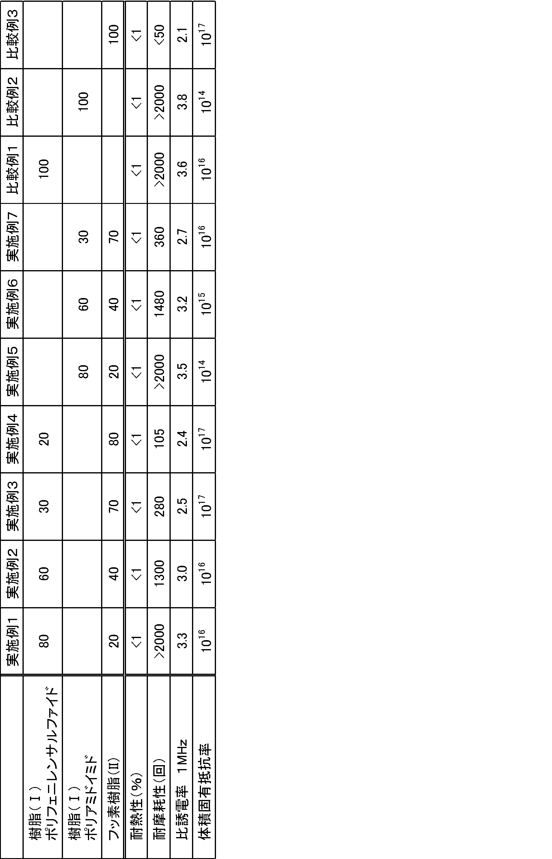
- Resin (I) Polyphenylene sulfide (trade name: “Fortron 0220A” manufactured by Polyplastics Co., Ltd., relative dielectric constant 3.6)
- Resin (I) Polyamideimide (trade name: “Toron TI-5013” manufactured by Toray Industries, Inc., relative dielectric constant 3.8)
- Fluororesin (II): Tetrafluoroethylene / hexafluoropropylene copolymer (composition weight ratio; tetrafluoroethylene / hexafluoropropylene / perfluoro (propyl vinyl ether) 87.5 / 11.5 / 1.0, relative dielectric Rate 2.1)
- the obtained resin composition pellets were supplied to an electric wire forming machine having a screw outer diameter of 30 mm ⁇ to produce a coated electric wire having a coating thickness of 0.1 mm using a copper stranded wire having an outer diameter of 1.0 mm ⁇ as a core wire.
- heat resistance evaluation, wear resistance evaluation, relative dielectric constant measurement, and volume resistivity were measured. The results are shown in Table 1.
- the insulated wire of the present invention includes an insulating layer having a low relative dielectric constant and is excellent in heat resistance and wear resistance, it can be suitably used for wrapping wires, automotive wires, robot wires, and the like. Moreover, since it is hard to produce the damage by winding processing, it can be used conveniently also as a coil winding (magnet wire). In particular, it is suitable for motors, rotating electrical machines, compressors, transformers, and the like.
Abstract
Description
CF2=CF-Rf1 (1)
(式中、Rf1は、-CF3または-ORf2を表す。Rf2は、炭素数1~5のパーフルオロアルキル基を表す。)で表されるパーフルオロエチレン性不飽和化合物の共重合体であることが好ましい。フッ素樹脂(II)は、テトラフルオロエチレンと、パーフルオロ(アルキルビニルエーテル)及びヘキサフルオロプロピレンからなる群より選択される少なくとも1種のパーフルオロモノマーとの共重合体であることがより好ましい。
本発明の絶縁電線は、上記構成を有することによって、優れた耐熱性及び耐摩耗性を有するとともに、絶縁層(B)が低い比誘電率を示すものである。本発明の絶縁電線は、絶縁層(B)が低い比誘電率を有するものであるため、部分放電電圧を高くすることができる。
導体(A)の外周に形成される絶縁層(B)は、導体(A)と接するものであってもよいし、導体(A)との間に、他の層、例えば他の樹脂層を介して形成されたものであってもよい。
絶縁層(B)は、導体(A)と接するものであることが好ましく、その場合、導体(A)と絶縁層(B)との接着が強固な絶縁電線が得られる。
樹脂(I)の比誘電率は、23℃、測定周波数1MHzで測定して得られた値である。上記比誘電率は、ネットワークアナライザを用いて、空洞共振器摂動法により測定することができる。
また、樹脂(I)は、絶縁電線の耐熱性がより優れることから、ポリイミド、ポリアミドイミド、ポリエーテルイミド、ポリアリーレンサルファイド、ポリアリレート、ポリスルホン、ポリエーテルスルホン及び、液晶ポリマーからなる群より選択される少なくとも1種であることが好ましい。また、連続使用温度が高く耐熱性に優れることから、ポリアリーレンサルファイド、ポリイミド、及びポリアミドイミドからなる群より選択される少なくとも1種であることがより好ましく、成形加工性がより優れることから、ポリアリーレンサルファイドが更に好ましい。
-(Ar-S)-
(式中、Arはアリーレン基、Sは硫黄を示す)で表わされる繰り返し単位を有するものが挙げられ、樹脂中の前記繰り返し単位の含有割合は70モル%以上が好ましい。
アリーレン基としては、p-フェニレン、m-フェニレン、o-フェニレン、アルキル置換フェニレン、フェニル置換フェニレン、ハロゲン置換フェニレン、アミノ置換フェニレン、アミド置換フェニレン、p,p’-ジフェニレンスルホン、p,p’-ビフェニレン、p,p’-ビフェニレンエーテル等を挙げることができる。
なお、ポリアリーレンサルファイドは、架橋や分岐構造を有する樹脂(架橋型)、架橋や分岐構造が実質的に有さない樹脂(リニア型)に大別することができるが、本発明では架橋型、リニア型のいずれでも問題なく使用することができる。
フッ素樹脂(B)としては、溶融加工性のフッ素樹脂が好ましい。溶融加工性のフッ素樹脂を用いることによって、本発明の絶縁電線は、より優れた耐摩耗性を有するものとなる。
フッ素樹脂(II)の比誘電率は、23℃、測定周波数1MHzで測定して得られた値である。上記比誘電率は、ネットワークアナライザを用いて、空洞共振器摂動法により測定することができる。
テトラフルオロエチレン(TFE)及び下記一般式(1):
CF2=CF-Rf1 (1)
(式中、Rf1は、-CF3又は-ORf2を表す。Rf2は、炭素数1~5のパーフルオロアルキル基を表す。)で表されるパーフルオロエチレン性不飽和化合物の共重合体であることが好ましい。上記フッ素樹脂(II)を用いることによって、フッ素樹脂(II)が樹脂(I)に対して効率よく分散し、本発明の絶縁電線における絶縁層(B)は、より優れた力学物性を示すと共に、絶縁性に優れ、低い比誘電率を示す。更に、絶縁層(B)と導体(A)との接着がより強固なものとなる。例えば、非溶融加工性のPTFEを用いた場合には、充分な力学物性を示さず、導体(A)との接着強度も低い。
フッ素樹脂(II)は、1種を用いてもよいし、2種以上を併用してもよい。
上記Rf1が、-ORf2である場合、上記Rf2は炭素数が1~3のパーフルオロアルキル基であることがより好ましい。
また、上記フッ素樹脂(II)を構成する上記一般式(1)で表されるパーフルオロエチレン性不飽和化合物の含有量の下限は、3モル%がより好ましく、5モル%が更に好ましい。上記フッ素樹脂(II)を構成する上記一般式(1)で表されるパーフルオロエチレン性不飽和化合物の含有量の上限は、15モル%がより好ましく、13モル%が更に好ましく、10モル%が特に好ましく、7モル%が殊更に好ましい。
上記フッ素樹脂(II)のMFRは、ASTM D3307-01に準拠し、メルトインデクサーを用いて測定する。
フッ素樹脂(II)の含有量が樹脂(I)との質量比で90を超えると、絶縁層(B)と導体(A)との接着強度や耐摩耗性が劣る傾向があり、2未満であると、比誘電率が上昇するおそれがある。より好ましい範囲は、90:10~15:85である。
また、フッ素樹脂(II)の含有量が樹脂(I)との質量比が相対的に少ない場合には、絶縁層(B)を構成する樹脂組成物のマトリックスは樹脂(I)となる傾向にあり、フッ素樹脂(II)の含有量が樹脂(I)との質量比が相対的に多い場合には、絶縁層(B)を構成する樹脂組成物のマトリックスはフッ素樹脂(II)となる傾向にある。
樹脂(I)とフッ素樹脂(II)の分散形態は、樹脂(I)のマトリックス中にフッ素樹脂(II)が分散する形態であっても、フッ素樹脂(II)のマトリックス中に樹脂(I)が分散する形態であってもよいが、樹脂(I)の分散粒子の平均分散粒子径が30μm以下であることが好ましく、10μm以下であることがより好ましい。
下記の実施例の樹脂組成物またはポリフェニレンサルファイド単独樹脂又はフッ素樹脂単独を使用して得られたフィルム(厚み25μm)を、幅2mm・長さ100mmの短冊状に切り出し、空洞共振器摂動法((株)関東電子応用開発製誘電率測定装置、アジレントテクノロジー(株)製ネットワークアナライザ)にて、1MHzにおける比誘電率を測定した。
下記の実施例の樹脂組成物またはポリフェニレンサルファイド単独樹脂又はフッ素樹脂単独を使用して得られたフィルム(厚み25μm)を使用して、四探針法(三菱化学(株)製 Loresta HP MCP-T410装置を使用)にて体積固有抵抗率を測定した。
下記の実施例の樹脂組成物またはポリフェニレンサルファイド単独樹脂又はフッ素樹脂単独を使用して得られたフィルム(厚み25μm)を、180℃のオーブンに入れ、1500時間、エージング処理を行った。その後、エージング後のフィルムからダンベル状切片を切り出し、引張強度を測定し、未処理の引張強度からの低下率を求めた。
下記の実施例または比較例で得られた絶縁電線を用いて、電線被覆摩耗試験器(東洋精機工業社製スクレープテスタ)を使用して、JIS-C3003に準じて、荷重300gの条件にて摩耗に至るまでの回数を測定した。
樹脂(I):ポリフェニレンサルファイド(商品名:ポリプラスチックス株式会社製「フォートロン 0220A」、比誘電率3.6)
樹脂(I):ポリアミドイミド(商品名:東レ株式会社製「トーロン TI-5013」、比誘電率3.8)
フッ素樹脂(II):テトラフルオロエチレン/ヘキサフルオロプロピレン共重合体(組成重量比;テトラフルオロエチレン/ヘキサフルオロプロピレン/パーフルオロ(プロピルビニルエーテル)=87.5/11.5/1.0、比誘電率2.1)
樹脂(I)およびフッ素樹脂(II)を表1に示す割合(質量部)で予備混合を行い、二軸押出機(φ30mm、L/D=35)を使用して、シリンダー温度330℃、スクリュウ回転数200rpmの条件下で溶融混練し、樹脂組成物のペレットを製造した。
得られた樹脂組成物ペレットをスクリュー外径30mmφの電線成形機に供給し、外径1.0mmφの銅撚り線を芯線とする被覆厚さ0.1mmの被覆電線を製造した。得られた被覆電線に関して、耐熱性評価、耐摩耗性評価、比誘電率の測定、体積固有抵抗率の測定を行った。結果を表1に示す。
樹脂(I)またはフッ素樹脂(II)のペレットをスクリュー外径30mmφの電線成形機に供給し、外径1.0mmφの銅撚り線を芯線とする被覆厚さ0.1mmの被覆電線を製造した。得られた被覆電線に関して、耐熱性評価、耐摩耗性評価、比誘電率の測定、体積固有抵抗率の測定を行った。結果を表1に示す。
Claims (6)
- 導体(A)と、
前記導体(A)の外周に形成される絶縁層(B)とを有する絶縁電線であって、
絶縁層(B)は、比誘電率が3.0~4.0の樹脂(I)と、フッ素樹脂(II)とを含む樹脂組成物から形成される
ことを特徴とする絶縁電線。 - フッ素樹脂(II)は、テトラフルオロエチレン及び下記一般式(1):
CF2=CF-Rf1 (1)
(式中、Rf1は、-CF3または-ORf2を表す。Rf2は、炭素数1~5のパーフルオロアルキル基を表す。)で表されるパーフルオロエチレン性不飽和化合物の共重合体である請求項1記載の絶縁電線。 - フッ素樹脂(II)は、テトラフルオロエチレンと、パーフルオロ(アルキルビニルエーテル)及びヘキサフルオロプロピレンからなる群より選択される少なくとも1種のパーフルオロモノマーとの共重合体である請求項1又は2記載の絶縁電線。
- 樹脂(I)は、ポリイミド、ポリアミドイミド、ポリエーテルイミド、ポリアリーレンサルファイド、ポリアリレート、ポリスルホン、ポリエーテルスルホン及び、液晶ポリマーからなる群より選択される少なくとも1種である請求項1、2又は3記載の絶縁電線。
- 樹脂(I)は、ポリアリーレンサルファイドである請求項1、2,3又は4記載の絶縁電線。
- 絶縁層(B)は、樹脂(I)とフッ素樹脂(II)との質量比(I):(II)が98:2~10:90である請求項1、2、3、4又は5記載の絶縁電線。
Priority Applications (4)
| Application Number | Priority Date | Filing Date | Title |
|---|---|---|---|
| CN201480004344.8A CN104903977B (zh) | 2013-01-17 | 2014-01-07 | 绝缘电线 |
| JP2014557423A JP6137198B2 (ja) | 2013-01-17 | 2014-01-07 | 絶縁電線 |
| EP14740261.4A EP2937870B1 (en) | 2013-01-17 | 2014-01-07 | Insulated wire |
| US14/760,562 US10991478B2 (en) | 2013-01-17 | 2014-01-07 | Insulated wire |
Applications Claiming Priority (2)
| Application Number | Priority Date | Filing Date | Title |
|---|---|---|---|
| JP2013006416 | 2013-01-17 | ||
| JP2013-006416 | 2013-01-17 |
Publications (1)
| Publication Number | Publication Date |
|---|---|
| WO2014112405A1 true WO2014112405A1 (ja) | 2014-07-24 |
Family
ID=51209497
Family Applications (1)
| Application Number | Title | Priority Date | Filing Date |
|---|---|---|---|
| PCT/JP2014/050069 WO2014112405A1 (ja) | 2013-01-17 | 2014-01-07 | 絶縁電線 |
Country Status (5)
| Country | Link |
|---|---|
| US (1) | US10991478B2 (ja) |
| EP (1) | EP2937870B1 (ja) |
| JP (1) | JP6137198B2 (ja) |
| CN (1) | CN104903977B (ja) |
| WO (1) | WO2014112405A1 (ja) |
Cited By (8)
| Publication number | Priority date | Publication date | Assignee | Title |
|---|---|---|---|---|
| JPWO2016031675A1 (ja) * | 2014-08-27 | 2017-06-08 | 旭硝子株式会社 | 絶縁電線及びその製造方法 |
| KR20180134841A (ko) * | 2016-04-11 | 2018-12-19 | 에이지씨 가부시키가이샤 | 적층체, 프린트 기판, 및 적층체의 제조 방법 |
| WO2019083031A1 (ja) * | 2017-10-26 | 2019-05-02 | 古河電気工業株式会社 | カーボンナノチューブ被覆電線 |
| WO2019083025A1 (ja) * | 2017-10-26 | 2019-05-02 | 古河電気工業株式会社 | カーボンナノチューブ被覆電線 |
| WO2019083028A1 (ja) * | 2017-10-26 | 2019-05-02 | 古河電気工業株式会社 | カーボンナノチューブ被覆電線 |
| WO2019083027A1 (ja) * | 2017-10-26 | 2019-05-02 | 古河電気工業株式会社 | カーボンナノチューブ被覆電線 |
| WO2020218205A1 (ja) * | 2019-04-26 | 2020-10-29 | ダイキン工業株式会社 | マグネット線およびコイル |
| WO2023149021A1 (ja) * | 2022-02-01 | 2023-08-10 | 住友電気工業株式会社 | マグネットワイヤ |
Families Citing this family (9)
| Publication number | Priority date | Publication date | Assignee | Title |
|---|---|---|---|---|
| EP3001429B1 (en) * | 2013-05-23 | 2017-10-04 | Asahi Glass Company, Limited | Covering material for heat resistant electric wire, its production method, and electric wire |
| JP6299619B2 (ja) * | 2015-01-30 | 2018-03-28 | 株式会社オートネットワーク技術研究所 | 絶縁電線 |
| JP2017157760A (ja) * | 2016-03-03 | 2017-09-07 | オムロン株式会社 | 光学電子機器 |
| JP2017183166A (ja) * | 2016-03-31 | 2017-10-05 | 株式会社オートネットワーク技術研究所 | 絶縁電線 |
| WO2017188397A1 (ja) * | 2016-04-28 | 2017-11-02 | 旭硝子株式会社 | 被覆電線 |
| CN108461202B (zh) * | 2017-02-22 | 2020-11-10 | 住友电气工业株式会社 | 多芯电缆 |
| USD942930S1 (en) | 2019-01-17 | 2022-02-08 | Hubbell Incorporated | Charge center |
| CN114270454A (zh) * | 2019-03-29 | 2022-04-01 | 美国埃赛克斯古河电磁线有限责任公司 | 具有热塑性绝缘部的磁导线 |
| CN113380463A (zh) * | 2021-06-09 | 2021-09-10 | 亳州联滔电子有限公司 | 柔性扁平线缆的制作方法及柔性扁平线缆 |
Citations (9)
| Publication number | Priority date | Publication date | Assignee | Title |
|---|---|---|---|---|
| JPH05225832A (ja) | 1992-02-07 | 1993-09-03 | Furukawa Electric Co Ltd:The | 絶縁電線 |
| JPH06215635A (ja) * | 1993-01-13 | 1994-08-05 | Furukawa Electric Co Ltd:The | 耐加工性絶縁電線 |
| JPH0817258A (ja) | 1994-06-30 | 1996-01-19 | Nissei Denki Kk | ポリエーテルエーテルケトン樹脂被覆電線・ケーブル |
| JP2010067521A (ja) | 2008-09-11 | 2010-03-25 | Sumitomo Electric Ind Ltd | 絶縁電線及びその製造方法、並びに、電気コイル及びモータ |
| JP2010123389A (ja) | 2008-11-19 | 2010-06-03 | Sumitomo Electric Ind Ltd | 絶縁電線 |
| WO2011024809A1 (ja) * | 2009-08-24 | 2011-03-03 | ダイキン工業株式会社 | 電線及びその製造方法 |
| JP2011159578A (ja) | 2010-02-03 | 2011-08-18 | Sumitomo Electric Wintec Inc | 絶縁電線及びそれを用いた電機コイル、モータ |
| JP2011165485A (ja) | 2010-02-10 | 2011-08-25 | Hitachi Cable Ltd | 絶縁電線 |
| JP2012243568A (ja) * | 2011-05-19 | 2012-12-10 | Hitachi Cable Ltd | 絶縁電線及びその製造方法 |
Family Cites Families (8)
| Publication number | Priority date | Publication date | Assignee | Title |
|---|---|---|---|---|
| US4362069A (en) * | 1979-04-02 | 1982-12-07 | Markel Corporation | High efficiency, abrasion resistant product and process |
| US6600108B1 (en) * | 2002-01-25 | 2003-07-29 | Schlumberger Technology Corporation | Electric cable |
| US20050161856A1 (en) * | 2004-01-23 | 2005-07-28 | Globus Yevgeniy I. | Extrusion jacketing process |
| US7288721B2 (en) * | 2004-12-28 | 2007-10-30 | Schlumberger Technology Corporation | Electrical cables |
| CN101880436B (zh) * | 2010-07-05 | 2012-05-30 | 清华大学 | 树脂组合物及其模塑品 |
| EP2767986B1 (en) | 2011-12-14 | 2019-11-13 | Daikin Industries, Ltd. | Insulated wire |
| JP5983725B2 (ja) | 2012-02-22 | 2016-09-06 | 旭硝子株式会社 | 含フッ素共重合体組成物、成型品および電線 |
| US10294362B2 (en) | 2012-08-06 | 2019-05-21 | Daikin Industries, Ltd. | Resin composition and molded article |
-
2014
- 2014-01-07 WO PCT/JP2014/050069 patent/WO2014112405A1/ja active Application Filing
- 2014-01-07 US US14/760,562 patent/US10991478B2/en active Active
- 2014-01-07 EP EP14740261.4A patent/EP2937870B1/en active Active
- 2014-01-07 JP JP2014557423A patent/JP6137198B2/ja active Active
- 2014-01-07 CN CN201480004344.8A patent/CN104903977B/zh active Active
Patent Citations (9)
| Publication number | Priority date | Publication date | Assignee | Title |
|---|---|---|---|---|
| JPH05225832A (ja) | 1992-02-07 | 1993-09-03 | Furukawa Electric Co Ltd:The | 絶縁電線 |
| JPH06215635A (ja) * | 1993-01-13 | 1994-08-05 | Furukawa Electric Co Ltd:The | 耐加工性絶縁電線 |
| JPH0817258A (ja) | 1994-06-30 | 1996-01-19 | Nissei Denki Kk | ポリエーテルエーテルケトン樹脂被覆電線・ケーブル |
| JP2010067521A (ja) | 2008-09-11 | 2010-03-25 | Sumitomo Electric Ind Ltd | 絶縁電線及びその製造方法、並びに、電気コイル及びモータ |
| JP2010123389A (ja) | 2008-11-19 | 2010-06-03 | Sumitomo Electric Ind Ltd | 絶縁電線 |
| WO2011024809A1 (ja) * | 2009-08-24 | 2011-03-03 | ダイキン工業株式会社 | 電線及びその製造方法 |
| JP2011159578A (ja) | 2010-02-03 | 2011-08-18 | Sumitomo Electric Wintec Inc | 絶縁電線及びそれを用いた電機コイル、モータ |
| JP2011165485A (ja) | 2010-02-10 | 2011-08-25 | Hitachi Cable Ltd | 絶縁電線 |
| JP2012243568A (ja) * | 2011-05-19 | 2012-12-10 | Hitachi Cable Ltd | 絶縁電線及びその製造方法 |
Cited By (13)
| Publication number | Priority date | Publication date | Assignee | Title |
|---|---|---|---|---|
| JPWO2016031675A1 (ja) * | 2014-08-27 | 2017-06-08 | 旭硝子株式会社 | 絶縁電線及びその製造方法 |
| KR20180134841A (ko) * | 2016-04-11 | 2018-12-19 | 에이지씨 가부시키가이샤 | 적층체, 프린트 기판, 및 적층체의 제조 방법 |
| KR102340434B1 (ko) * | 2016-04-11 | 2021-12-16 | 에이지씨 가부시키가이샤 | 적층체, 프린트 기판, 및 적층체의 제조 방법 |
| CN111279435A (zh) * | 2017-10-26 | 2020-06-12 | 古河电气工业株式会社 | 碳纳米管包覆电线 |
| WO2019083028A1 (ja) * | 2017-10-26 | 2019-05-02 | 古河電気工業株式会社 | カーボンナノチューブ被覆電線 |
| WO2019083027A1 (ja) * | 2017-10-26 | 2019-05-02 | 古河電気工業株式会社 | カーボンナノチューブ被覆電線 |
| WO2019083025A1 (ja) * | 2017-10-26 | 2019-05-02 | 古河電気工業株式会社 | カーボンナノチューブ被覆電線 |
| CN111279436A (zh) * | 2017-10-26 | 2020-06-12 | 古河电气工业株式会社 | 碳纳米管包覆电线 |
| WO2019083031A1 (ja) * | 2017-10-26 | 2019-05-02 | 古河電気工業株式会社 | カーボンナノチューブ被覆電線 |
| CN111279436B (zh) * | 2017-10-26 | 2022-04-05 | 古河电气工业株式会社 | 碳纳米管包覆电线 |
| WO2020218205A1 (ja) * | 2019-04-26 | 2020-10-29 | ダイキン工業株式会社 | マグネット線およびコイル |
| CN113710732A (zh) * | 2019-04-26 | 2021-11-26 | 大金工业株式会社 | 电磁线和线圈 |
| WO2023149021A1 (ja) * | 2022-02-01 | 2023-08-10 | 住友電気工業株式会社 | マグネットワイヤ |
Also Published As
| Publication number | Publication date |
|---|---|
| JP6137198B2 (ja) | 2017-05-31 |
| JPWO2014112405A1 (ja) | 2017-01-19 |
| US10991478B2 (en) | 2021-04-27 |
| CN104903977B (zh) | 2018-12-28 |
| US20150357084A1 (en) | 2015-12-10 |
| EP2937870A4 (en) | 2016-08-17 |
| EP2937870A1 (en) | 2015-10-28 |
| EP2937870B1 (en) | 2019-09-18 |
| CN104903977A (zh) | 2015-09-09 |
Similar Documents
| Publication | Publication Date | Title |
|---|---|---|
| JP6137198B2 (ja) | 絶縁電線 | |
| JP5975042B2 (ja) | 絶縁電線 | |
| WO2016103804A1 (ja) | 耐曲げ加工性に優れる絶縁電線、それを用いたコイルおよび電子・電気機器 | |
| KR101988092B1 (ko) | 절연 와이어, 코일 및 전기전자기기와 피막박리 방지 절연 와이어의 제조방법 | |
| CN109074909B (zh) | 绝缘电线、线圈和电气/电子设备 | |
| JP5757358B2 (ja) | 熱可塑性樹脂組成物および成形品 | |
| JP6839695B2 (ja) | 絶縁電線、モーターコイルおよび電気・電子機器 | |
| WO2015098637A1 (ja) | 絶縁ワイヤ、モーターコイル、電気・電子機器および絶縁ワイヤの製造方法 | |
| JP2010123389A (ja) | 絶縁電線 | |
| JP6015846B2 (ja) | 電気絶縁部品 | |
| JP5737464B2 (ja) | 組成物及び絶縁電線 | |
| JP6932642B2 (ja) | 絶縁電線、絶縁電線の製造方法、コイル、回転電機および電気・電子機器 | |
| KR102166630B1 (ko) | 절연 전선, 코일 및 전기·전자 기기 | |
| JP2011071089A (ja) | 電線及びその製造方法 | |
| JP2008226853A (ja) | 耐インバータサージ絶縁ワイヤおよびその製造方法 | |
| JP6604104B2 (ja) | 絶縁電線及びその製造方法 | |
| WO2023135852A1 (ja) | 絶縁電線、コイル、回転電機および電気・電子機器 | |
| KR20230004822A (ko) | 권선에 사용하기 위한 절연 도체, 그로부터 유래된 권선 및 상응하는 제조 방법 | |
| JP2017068971A (ja) | 絶縁電線 |
Legal Events
| Date | Code | Title | Description |
|---|---|---|---|
| 121 | Ep: the epo has been informed by wipo that ep was designated in this application |
Ref document number: 14740261 Country of ref document: EP Kind code of ref document: A1 |
|
| ENP | Entry into the national phase |
Ref document number: 2014557423 Country of ref document: JP Kind code of ref document: A |
|
| WWE | Wipo information: entry into national phase |
Ref document number: 14760562 Country of ref document: US |
|
| NENP | Non-entry into the national phase |
Ref country code: DE |
|
| WWE | Wipo information: entry into national phase |
Ref document number: 2014740261 Country of ref document: EP |