WO2014087997A1 - アクチュエータ - Google Patents
アクチュエータ Download PDFInfo
- Publication number
- WO2014087997A1 WO2014087997A1 PCT/JP2013/082470 JP2013082470W WO2014087997A1 WO 2014087997 A1 WO2014087997 A1 WO 2014087997A1 JP 2013082470 W JP2013082470 W JP 2013082470W WO 2014087997 A1 WO2014087997 A1 WO 2014087997A1
- Authority
- WO
- WIPO (PCT)
- Prior art keywords
- housing
- wall
- air hole
- actuator
- shielding wall
- Prior art date
- Legal status (The legal status is an assumption and is not a legal conclusion. Google has not performed a legal analysis and makes no representation as to the accuracy of the status listed.)
- Ceased
Links
Images



Classifications
-
- B—PERFORMING OPERATIONS; TRANSPORTING
- B60—VEHICLES IN GENERAL
- B60L—PROPULSION OF ELECTRICALLY-PROPELLED VEHICLES; SUPPLYING ELECTRIC POWER FOR AUXILIARY EQUIPMENT OF ELECTRICALLY-PROPELLED VEHICLES; ELECTRODYNAMIC BRAKE SYSTEMS FOR VEHICLES IN GENERAL; MAGNETIC SUSPENSION OR LEVITATION FOR VEHICLES; MONITORING OPERATING VARIABLES OF ELECTRICALLY-PROPELLED VEHICLES; ELECTRIC SAFETY DEVICES FOR ELECTRICALLY-PROPELLED VEHICLES
- B60L53/00—Methods of charging batteries, specially adapted for electric vehicles; Charging stations or on-board charging equipment therefor; Exchange of energy storage elements in electric vehicles
- B60L53/10—Methods of charging batteries, specially adapted for electric vehicles; Charging stations or on-board charging equipment therefor; Exchange of energy storage elements in electric vehicles characterised by the energy transfer between the charging station and the vehicle
- B60L53/14—Conductive energy transfer
- B60L53/16—Connectors, e.g. plugs or sockets, specially adapted for charging electric vehicles
-
- B—PERFORMING OPERATIONS; TRANSPORTING
- B60—VEHICLES IN GENERAL
- B60L—PROPULSION OF ELECTRICALLY-PROPELLED VEHICLES; SUPPLYING ELECTRIC POWER FOR AUXILIARY EQUIPMENT OF ELECTRICALLY-PROPELLED VEHICLES; ELECTRODYNAMIC BRAKE SYSTEMS FOR VEHICLES IN GENERAL; MAGNETIC SUSPENSION OR LEVITATION FOR VEHICLES; MONITORING OPERATING VARIABLES OF ELECTRICALLY-PROPELLED VEHICLES; ELECTRIC SAFETY DEVICES FOR ELECTRICALLY-PROPELLED VEHICLES
- B60L2240/00—Control parameters of input or output; Target parameters
- B60L2240/10—Vehicle control parameters
- B60L2240/36—Temperature of vehicle components or parts
-
- B—PERFORMING OPERATIONS; TRANSPORTING
- B60—VEHICLES IN GENERAL
- B60L—PROPULSION OF ELECTRICALLY-PROPELLED VEHICLES; SUPPLYING ELECTRIC POWER FOR AUXILIARY EQUIPMENT OF ELECTRICALLY-PROPELLED VEHICLES; ELECTRODYNAMIC BRAKE SYSTEMS FOR VEHICLES IN GENERAL; MAGNETIC SUSPENSION OR LEVITATION FOR VEHICLES; MONITORING OPERATING VARIABLES OF ELECTRICALLY-PROPELLED VEHICLES; ELECTRIC SAFETY DEVICES FOR ELECTRICALLY-PROPELLED VEHICLES
- B60L2270/00—Problem solutions or means not otherwise provided for
- B60L2270/30—Preventing theft during charging
- B60L2270/32—Preventing theft during charging of electricity
-
- B—PERFORMING OPERATIONS; TRANSPORTING
- B60—VEHICLES IN GENERAL
- B60L—PROPULSION OF ELECTRICALLY-PROPELLED VEHICLES; SUPPLYING ELECTRIC POWER FOR AUXILIARY EQUIPMENT OF ELECTRICALLY-PROPELLED VEHICLES; ELECTRODYNAMIC BRAKE SYSTEMS FOR VEHICLES IN GENERAL; MAGNETIC SUSPENSION OR LEVITATION FOR VEHICLES; MONITORING OPERATING VARIABLES OF ELECTRICALLY-PROPELLED VEHICLES; ELECTRIC SAFETY DEVICES FOR ELECTRICALLY-PROPELLED VEHICLES
- B60L2270/00—Problem solutions or means not otherwise provided for
- B60L2270/30—Preventing theft during charging
- B60L2270/34—Preventing theft during charging of parts
-
- H—ELECTRICITY
- H01—ELECTRIC ELEMENTS
- H01R—ELECTRICALLY-CONDUCTIVE CONNECTIONS; STRUCTURAL ASSOCIATIONS OF A PLURALITY OF MUTUALLY-INSULATED ELECTRICAL CONNECTING ELEMENTS; COUPLING DEVICES; CURRENT COLLECTORS
- H01R13/00—Details of coupling devices of the kinds covered by groups H01R12/70 or H01R24/00 - H01R33/00
- H01R13/62—Means for facilitating engagement or disengagement of coupling parts or for holding them in engagement
- H01R13/627—Snap or like fastening
- H01R13/6271—Latching means integral with the housing
- H01R13/6272—Latching means integral with the housing comprising a single latching arm
-
- H—ELECTRICITY
- H01—ELECTRIC ELEMENTS
- H01R—ELECTRICALLY-CONDUCTIVE CONNECTIONS; STRUCTURAL ASSOCIATIONS OF A PLURALITY OF MUTUALLY-INSULATED ELECTRICAL CONNECTING ELEMENTS; COUPLING DEVICES; CURRENT COLLECTORS
- H01R13/00—Details of coupling devices of the kinds covered by groups H01R12/70 or H01R24/00 - H01R33/00
- H01R13/62—Means for facilitating engagement or disengagement of coupling parts or for holding them in engagement
- H01R13/639—Additional means for holding or locking coupling parts together, after engagement, e.g. separate keylock, retainer strap
- H01R13/6397—Additional means for holding or locking coupling parts together, after engagement, e.g. separate keylock, retainer strap with means for preventing unauthorised use
-
- Y—GENERAL TAGGING OF NEW TECHNOLOGICAL DEVELOPMENTS; GENERAL TAGGING OF CROSS-SECTIONAL TECHNOLOGIES SPANNING OVER SEVERAL SECTIONS OF THE IPC; TECHNICAL SUBJECTS COVERED BY FORMER USPC CROSS-REFERENCE ART COLLECTIONS [XRACs] AND DIGESTS
- Y02—TECHNOLOGIES OR APPLICATIONS FOR MITIGATION OR ADAPTATION AGAINST CLIMATE CHANGE
- Y02T—CLIMATE CHANGE MITIGATION TECHNOLOGIES RELATED TO TRANSPORTATION
- Y02T10/00—Road transport of goods or passengers
- Y02T10/60—Other road transportation technologies with climate change mitigation effect
- Y02T10/70—Energy storage systems for electromobility, e.g. batteries
-
- Y—GENERAL TAGGING OF NEW TECHNOLOGICAL DEVELOPMENTS; GENERAL TAGGING OF CROSS-SECTIONAL TECHNOLOGIES SPANNING OVER SEVERAL SECTIONS OF THE IPC; TECHNICAL SUBJECTS COVERED BY FORMER USPC CROSS-REFERENCE ART COLLECTIONS [XRACs] AND DIGESTS
- Y02—TECHNOLOGIES OR APPLICATIONS FOR MITIGATION OR ADAPTATION AGAINST CLIMATE CHANGE
- Y02T—CLIMATE CHANGE MITIGATION TECHNOLOGIES RELATED TO TRANSPORTATION
- Y02T10/00—Road transport of goods or passengers
- Y02T10/60—Other road transportation technologies with climate change mitigation effect
- Y02T10/7072—Electromobility specific charging systems or methods for batteries, ultracapacitors, supercapacitors or double-layer capacitors
-
- Y—GENERAL TAGGING OF NEW TECHNOLOGICAL DEVELOPMENTS; GENERAL TAGGING OF CROSS-SECTIONAL TECHNOLOGIES SPANNING OVER SEVERAL SECTIONS OF THE IPC; TECHNICAL SUBJECTS COVERED BY FORMER USPC CROSS-REFERENCE ART COLLECTIONS [XRACs] AND DIGESTS
- Y02—TECHNOLOGIES OR APPLICATIONS FOR MITIGATION OR ADAPTATION AGAINST CLIMATE CHANGE
- Y02T—CLIMATE CHANGE MITIGATION TECHNOLOGIES RELATED TO TRANSPORTATION
- Y02T90/00—Enabling technologies or technologies with a potential or indirect contribution to GHG emissions mitigation
- Y02T90/10—Technologies relating to charging of electric vehicles
- Y02T90/14—Plug-in electric vehicles
-
- Y—GENERAL TAGGING OF NEW TECHNOLOGICAL DEVELOPMENTS; GENERAL TAGGING OF CROSS-SECTIONAL TECHNOLOGIES SPANNING OVER SEVERAL SECTIONS OF THE IPC; TECHNICAL SUBJECTS COVERED BY FORMER USPC CROSS-REFERENCE ART COLLECTIONS [XRACs] AND DIGESTS
- Y02—TECHNOLOGIES OR APPLICATIONS FOR MITIGATION OR ADAPTATION AGAINST CLIMATE CHANGE
- Y02T—CLIMATE CHANGE MITIGATION TECHNOLOGIES RELATED TO TRANSPORTATION
- Y02T90/00—Enabling technologies or technologies with a potential or indirect contribution to GHG emissions mitigation
- Y02T90/10—Technologies relating to charging of electric vehicles
- Y02T90/16—Information or communication technologies improving the operation of electric vehicles
Definitions
- the present invention relates to an actuator.
- the storage battery When charging a storage battery mounted on a vehicle such as an electric vehicle or a hybrid vehicle, the storage battery is powered by attaching the charging connector of the charging cable to the power receiving connector provided on the vehicle body.
- a lock mechanism for preventing the charging connector from being detached from the power receiving connector a hook provided on the charging connector so as to be tiltable, an engagement protrusion provided on the power receiving connector, and an actuator provided around the power receiving connector;
- the actuator has a resin housing in which a drive mechanism is accommodated.
- the lock pin protruding from the housing can be moved back and forth with respect to the housing.
- the housing is attached to the inner surface of the wall portion of the charging port of the vehicle body.
- the lock pin protrudes outward through the insertion hole in the wall portion of the charging port.
- the hook of the charging connector is engaged with the engaging protrusion of the power receiving connector. Further, the lock pin of the actuator advances to a position where the tilt of the hook is restricted. Thereby, since the hook is fixed in a state of being engaged with the engaging protrusion, it is possible to prevent the charging connector from being detached from the power receiving connector.
- An object of the present invention is to solve the above-described problems and to provide an actuator that makes it difficult for grease in the housing to flow into an air hole penetrating the wall portion of the housing.
- the present invention is an actuator in which a housing space in which a drive mechanism is housed is formed by combining a lower housing lower and an upper housing upper.
- a shielding wall is erected on the bottom surface of the housing lower, and an air hole communicating with the space surrounded by the shielding wall passes through the housing lower.
- a partition wall is formed on the inner surface of the housing upper so as to face the side surface of the shielding wall.
- a partition wall may oppose the outer surface of a shielding wall in an accommodation space, and may oppose the inner surface of a shielding wall.
- the inside and outside of the housing can be ventilated through the air hole.
- the moisture-permeable and waterproof material may be provided in the outer opening of the air hole or in the inner opening of the air hole.
- the air hole may be formed in a peripheral wall portion of the housing lower, and the air hole may be closed with the moisture-permeable waterproof material.
- the moisture-permeable waterproof material can be prevented from being exposed to the outside, and water and dust can be prevented from adhering to the moisture-permeable waterproof material from the outside.
- the air hole is formed at the bottom of the housing lower, it is possible to prevent the air hole from being exposed to the side of the housing.
- a convex wall is provided around the outer opening on the outer surface of the housing lower, and the lid It is desirable that the portion be disposed to face the outer opening and the convex wall. Furthermore, it is desirable to form a part with a smaller protrusion amount than the other part in a part of the convex wall.
- the actuator of the present invention when the actuator of the present invention is applied to a vehicle, it is desirable to arrange a portion where the protruding amount of the convex wall is large on the front side of the vehicle and a portion where the protruding amount of the convex wall is small on the rear side of the vehicle. . If it does in this way, traveling wind and rain water from the front of vehicles can be intercepted by a part with a large projection amount of a convex wall.
- the partition wall is formed along the side surface of the shielding wall, and the gap between the partition wall and the shielding wall is narrowed as a whole so that the grease does not easily flow into the air hole.
- the air passage from the accommodation space to the air hole has a labyrinth shape, it is difficult for grease to flow into the air hole from the accommodation space. Therefore, the inside and outside of the housing can be reliably ventilated through the air hole, and the pressure difference between the inside and outside of the housing can be suppressed.
- FIG. 1A is a front sectional view
- FIG. 1B is the figure which showed the shielding wall and air hole of 1st embodiment
- (a) is the side view seen from the exterior of a housing lower
- (b) is the side view seen from the inside of a housing lower.
- the actuator 10 constitutes a lock mechanism 5 that is installed in a charging port 2 a of a vehicle 1 such as an electric vehicle or a hybrid vehicle.
- the lock mechanism 5 prevents the charging connector 4 from being detached from the power receiving connector 3 when charging a storage battery (not shown) mounted on the vehicle 1.
- “upper and lower”, “front and rear”, and “left and right” of the actuator 10 are set for convenience in describing the structure of the actuator 10, and do not limit the orientation of the actuator 10. .
- FIG. 1 shows a state in which the actuator 10 of the first embodiment is mounted on a vehicle.
- the actuator 10 of the first embodiment has a rear side facing downward about 30 degrees with respect to a horizontal plane. It is attached to the vehicle in a tilted state.
- the charging port 2a of the vehicle body 2 is a space in which the leading end of the power receiving connector 3 is accommodated.
- the power receiving connector 3 is inserted through the opening of the wall 2b of the charging port 2a, and the tip of the power receiving connector 3 projects into the charging port 2a.
- the power receiving connector 3 is electrically connected to a storage battery (not shown) via a cable (not shown).
- the power receiving connector 3 is inclined about 30 degrees with respect to the horizontal plane so that the power receiving connector 3 is lowered from the front end side toward the vehicle inner side.
- the charging cable 4a is provided in a charging device (not shown) such as a charging station.
- a charging connector 4 is provided at the tip of the charging cable 4a. By attaching the charging connector 4 to the power receiving connector 3, power can be supplied from the charging device to the storage battery (not shown) through the charging cable 4a.
- the lock mechanism 5 includes a hook 4 b provided at the front end of the charging connector 4, an engagement protrusion 3 b formed at the front end of the power receiving connector 3, and an actuator 10 provided above the power receiving connector 3.
- the hook 4b can tilt up and down.
- the hook 4b in contact with the engaging protrusion 3b tilts upward.
- the hook 4b gets over the engaging protrusion 3b, the hook 4b tilts downward, and the hook 4b and the engaging protrusion 3b are engaged.
- the hook 4 b is hooked on the engaging protrusion 3 b, so that the charging connector 4 cannot be pulled out from the power receiving connector 3.
- the actuator 10 regulates the tilt of the hook 4b in a state where the hook 4b is engaged with the engagement protrusion 3b.
- the actuator 10 includes a housing 20 in which a drive mechanism is accommodated, and a lock pin 50 protruding from the front surface of the housing 20.
- the housing 20 is arranged on the vehicle interior side of the wall 2b of the charging port 2a.
- the lock pin 50 is movable forward and backward with respect to the housing 20 and protrudes into the charging port 2a through an insertion hole formed in the wall 2b.
- the housing 20 is a resin box as shown in FIG. 2, and the lock pin 50 protrudes from the front surface 34a.
- the housing 20 includes a housing lower 30 in which the internal space is the accommodation space 31, and a housing upper 40 that closes the opening 32 of the housing lower 30.
- a housing space 31 is formed in the housing 20 by combining the housing lower 30 and the housing upper 40.
- the housing lower 30 is a box-shaped member having an opening 32 formed on the upper surface.
- the housing lower 30 includes a flat bottom portion 33 and a peripheral wall portion 34 erected on the outer peripheral edge portion of the bottom portion 33.
- the peripheral wall portion 34 is a frame surrounding the accommodation space 31 and is formed in a substantially rectangular shape in plan view.
- the bottom 33 is formed in a substantially square shape in plan view (see FIG. 4).
- a male connector 35 protrudes downward from the right rear portion of the bottom 33.
- the male connector 35 is fitted with a female connector (not shown) for supplying power to the drive mechanism.
- the female connector is electrically connected to a control device (not shown) mounted on the vehicle 1 (see FIG. 1).
- a mounting portion 36a attached to the inner surface of the wall portion 2b (see FIG. 1) of the charging port 2a is projected from the front surface 34a of the peripheral wall portion 34 of the housing lower 30.
- two left and right housing support portions 36b attached to the power receiving connector 3 (see FIG. 1) are formed on the lower surface of the housing lower 30, two left and right housing support portions 36b attached to the power receiving connector 3 (see FIG. 1) are formed.
- the opening edge portion 37 of the housing lower 30 protrudes outwardly from the outer surface of the peripheral wall portion 34 in a flange shape.
- a seal groove 37a into which an endless seal member (not shown) is fitted is formed on the upper surface of the opening edge 37 (see FIG. 4).
- the housing upper 40 is a flat lid member for closing the opening 32 of the housing lower 30.
- the outer peripheral shape of the housing upper 40 is formed in the same shape as the outer peripheral shape of the opening edge portion 37 of the housing lower 30.
- the outer peripheral edge of the housing upper 40 is engaged with the opening edge 37 of the housing lower 30 and is bonded to the opening edge 37 with an adhesive such as hot melt. Further, the space between the housing lower 30 and the housing upper 40 is liquid-tightly sealed by a seal member (not shown) provided at the opening edge 37 of the housing lower 30.
- the lock pin 50 is a shaft member having a circular cross section, and the axial direction is arranged in the front-rear direction.
- the front end portion of the lock pin 50 is formed in a hemispherical surface.
- the rear portion of the lock pin 50 is housed in the housing space 31 of the housing lower 30, and the front portion of the lock pin 50 projects outward from the front surface 34 a of the peripheral wall portion 34.
- a holder 60 that holds the lock pin 50 and a cam member 70 that has a cam gear 72 from which a cam 73 protrudes are housed.
- an electric motor 80, a drive transmission member 90 interposed between the output shaft 81 of the electric motor 80 and the cam gear 72, a switch 110 for detecting the position of the lock pin 50, and an electric motor A substrate 100 to which the motor 80 and the switch 110 are electrically connected is accommodated.
- the cam member 70 is a member for moving the holder 60 in the front-rear direction.
- the cam member 70 includes a rotation shaft 71 whose axial direction is arranged in the vertical direction, a cam gear 72 that is a spur gear having the rotation shaft 71 as a central axis, and a cam 73 that projects from the lower surface of the cam gear 72. ing.
- the cam 53 is eccentric with respect to the rotation center of the cam gear 72.
- the lower part of the rotating shaft 71 is inserted into a cam housing frame 62 described later (see FIG. 4).
- the upper and lower ends of the rotation shaft 71 are rotatably supported by the lower surface 40b (see FIG. 5A) of the housing upper 40 and the bottom surface 33a of the housing lower 30.
- the upper end portion of the rotating shaft 71 protrudes outside through the through hole of the housing upper 40.
- the cam gear 72 is formed with a rod 72a protruding outward (see FIG. 4).
- the rod 72a is a part that pushes in a detection unit of the switch 110 (see FIG. 3) on the advancing side described later.
- the output shaft 81 of the electric motor 80 protrudes from the motor housing 82.
- a cylindrical screw gear 81 a is fitted on the output shaft 81.
- the drive transmission member 90 is a rotating shaft 91 whose axial direction is arranged in the vertical direction, a lower gear 92 that is a helical gear having the rotating shaft 91 as a central axis, and a spur gear that has the rotating shaft 91 as a central axis. And an upper gear 93.
- the upper and lower ends of the rotation shaft 91 are rotatably supported by the lower surface 40b (see FIG. 5A) of the housing upper 40 and the bottom surface 33a of the housing lower 30.
- the lower gear 92 is connected to the screw gear 81 a of the electric motor 80.
- the upper gear 93 is connected to the cam gear 72.
- the cam 73 is configured to rotate about the axis of the rotating shaft 71 by rotating the cam gear 72 about the axis.
- the holder 60 is mounted on the bottom surface 33a of the housing lower 30 so as to be movable in the front-rear direction.
- a rear portion of the lock pin 50 is attached to the front end surface of the holder 60, and a cam housing frame 62 in which the cam 73 is housed is opened at the rear portion of the holder 60.
- the cam housing frame 62 opens in the vertical direction, and the cam 73 is inserted from above.
- the inner peripheral surface of the cam housing frame 62 is a cam receiving surface with which the cam 73 abuts.
- a rod 63 protruding toward the right side is formed at the front portion of the holder 60.
- the rod 63 is a part that pushes in a detecting portion of a retreat-side switch 110 (see FIG. 3) described later.
- the substrate 100 is formed wide in the left-right direction, and is disposed above the electric motor 80 and the holder 60.
- the substrate 100 controls the driving of the electric motor 80.
- the electric motor 80, the switch 110, and the male connector 35 are electrically connected to the substrate 100.
- the switch 110 is attached to the lower surface of the substrate 100.
- the two switches 110 and 110 are juxtaposed in the left-right direction.
- Each of the switches 110 and 110 is disposed above the moving area of the rod 72a of the cam gear 72 and the rod 63 of the holder 60, respectively.
- the lock pin 50 retreats with respect to the housing 20, and the front portion of the lock pin 50 retreats from above the hook 4 b of the charging connector 4. To do.
- the hook 4 b can be tilted, the hook 4 b can be detached from the engagement protrusion 3 b of the power receiving connector 3, and the charging connector 4 can be pulled out from the power receiving connector 3.
- an unlocking lever 42 attached to the upper end portion of the rotating shaft 71 of the cam member 70 is provided (see FIG. 2).
- the cam member 70 can be forcibly rotated manually and the lock pin 50 can be retracted.
- the actuator 10 includes a shielding wall 210 erected on the bottom surface 33 a of the housing lower 30 and an air hole 220 passing through the peripheral wall portion 34 of the housing lower 30.
- a partition wall 230 formed on the lower surface 40 b of the housing upper 40 and a lid 240 formed on the outer peripheral edge of the housing upper 40 are formed.
- the air hole 220 communicates with the internal space 210 a surrounded by the peripheral wall portion 34 and the shielding wall 210.
- the shielding wall 210 is an L-shaped wall in a plan view that is erected on the right front portion of the bottom surface 33 a of the housing lower 30. Both side edge portions of the shielding wall 210 are connected to the inner surface of the peripheral wall portion 34, and as shown in FIG. 5B, a rectangular interior that is wide in the front-rear direction in a plan view by the peripheral wall portion 34 and the shielding wall 210. A space 210a is formed. Thereby, in the bottom 33 of the housing lower 30, the bottom surface 33 a that is the inner surface on the accommodation space 31 side is partitioned by the shielding wall 210 into a region surrounded by the peripheral wall portion 34 and the shielding wall 210 and other regions. ing.
- the internal space 210a is a space surrounded by a part of the front wall 34b and the right side wall 34c of the peripheral wall portion 34, and the rear inner wall 211 and the left inner wall 212 constituting the shielding wall 210, and the upper surface of the inner space 210a. Is open.
- the rear inner wall 211 is formed along the inner surface of the front wall 34b.
- the left inner wall 212 is formed along the inner surface of the right wall 34c. As shown in FIG. 5A, the rear inner wall 211 is formed higher than the left inner wall 212.
- the air hole 220 is a through hole having a circular cross section formed in the front part of the right side wall 34 c of the peripheral wall part 34.
- the air hole 220 penetrates from the outer surface to the inner surface of the peripheral wall portion 34.
- the inner opening 220 a of the air hole 220 is formed at a position (height) that is closer to the bottom surface 33 a than the upper edge of the left inner wall 212.
- the air hole 220 is disposed at a high position of the housing lower 30 when the housing lower 30 is attached to the power receiving connector 3 in an inclined state.
- a U-shaped convex wall 250 protrudes from the outer surface of the peripheral wall portion 34 around the outer opening 220 b of the air hole 220 in a side view.
- a notch 251 for draining and venting is formed at the lower part of the convex wall 250.
- the convex wall 250 is divided into a front convex wall 252 and a rear convex wall 253 with the notch 251 as a boundary.
- the protruding amount (height) of the rear convex wall 253 is smaller than that of the front convex wall 252.
- the notch portion 251 is disposed so as to be disposed at the lowermost portion of the convex wall 250 when the housing lower 30 is attached to the power receiving connector 3 in an inclined state. As a result, when the actuator 10 is attached to the power receiving connector 3, the notch 251 is arranged at a position optimal for draining the convex wall 250.
- the outer opening 220b of the air hole 220 is covered with a circular moisture permeable waterproof material 221 (see FIG. 6A).
- the moisture permeable and waterproof material 221 is a material that prevents the entry and exit of water while permitting the entry and exit of air, and can prevent water and dust from entering the air holes 220 from the external space.
- the moisture permeable waterproof material 221 is formed to have a larger diameter than the outer opening 220b.
- the moisture permeable waterproof material 221 is affixed to an area surrounded by the convex wall 250 on the outer surface of the peripheral wall portion 34 by an adhesive means such as a double-sided tape.
- the fingertips need to enter the area surrounded by the convex wall 250.
- the fingertip can smoothly enter the region from the side of the rear convex wall 253 having a small protrusion amount (height) (see FIG. 5B). Therefore, the moisture permeable waterproof material 221 can be reliably pressed around the outer opening 220b.
- the partition wall 230 is a flat wall that protrudes downward from the lower surface 40 b of the housing upper 40.
- the partition wall 230 is formed to be wide in the front-rear direction (see FIG. 5B), and has a side surface disposed to face the side surface of the shielding wall 210.
- the lower portion of the partition wall 230 is inserted into the internal space 210 a surrounded by the peripheral wall portion 34 and the shielding wall 210.
- the lower part of the partition wall 230 is arrange
- the partition wall 230 and the left inner wall 212 overlap in the height direction, and the lower part of the partition wall 230 is surrounded by the peripheral wall portion 34 and the shielding wall 210.
- the partition wall 230 is formed wider than the inner opening 220a of the air hole 220 (see FIG. 5B), and the lower end edge of the partition wall 230 is closer to the bottom surface 33a than the inner opening 220a. Placed in. That is, the inner opening 220 a of the air hole 220 is covered with the partition wall 230.
- a gap is formed between the upper end edge of the shielding wall 210 and the lower surface 40 b of the housing upper 40.
- a gap is formed between the partition wall 230 and the shielding wall 210.
- a gap is formed between the lower edge of the partition wall 230 and the bottom surface 33a.
- a plate-like lid portion 240 that protrudes downward is formed at the right front portion of the outer peripheral edge portion of the housing upper 40.
- the lid 240 is disposed to face the outer opening 220 b and the convex wall 250 when the housing upper 40 is assembled to the housing lower 30.
- the cover part 240 inclines so that it may approach the outer surface of the surrounding wall part 34 as it goes to a rear edge part from a front edge part, as shown in FIG.5 (b).
- a front rib 241 is formed on the front edge of the lid 240.
- a rear rib 242 is formed at the rear edge of the lid 240.
- the front rib 241 and the rear rib 242 are parallel to each other and extend in the vertical direction.
- the front rib 241 is a part that contacts the front convex wall 252 from the outside.
- the rear rib 242 is a part that contacts the rear convex wall 253 from the outside.
- the front rib 241 has a larger protruding amount than the rear rib 242, and the wrap amount between the front convex wall 252 and the front rib 241 is large.
- an air passage is formed from the accommodation space 31 to the external space through the gap between the partition wall 230 and the shielding wall 210 and the air hole 220.
- the inside and outside of the housing 20 can be ventilated through this ventilation path.
- the partition wall 230 overlaps the shielding wall 210 when the housing upper 40 is assembled to the housing lower 30.
- a ventilation path having a labyrinth shape from the accommodation space 31 to the air hole 220 (a shape in which the inner opening 220a of the air hole 220 cannot be seen from the accommodation space 31 side) is formed.
- the air passage from the accommodation space 31 to the air hole 220 has a labyrinth shape, and as shown in FIG. 5B, the gap between the partition wall 230 and the left inner wall 212 is narrowed as a whole. Therefore, it is difficult for grease to flow into the air hole 220. Therefore, the inside and outside of the housing 20 can be reliably ventilated through the air hole 220, and the pressure difference between the inside and outside of the housing 20 can be suppressed.
- the moisture permeable waterproof material 221 since the outer opening 220b of the air hole 220 is blocked by the moisture permeable waterproof material 221, water and dust are prevented from passing through the air hole 220 from the outside space, and the inside and outside of the housing 20 are passed through the air hole 220. Can be aerated. Moreover, since it is difficult for grease to flow into the air holes 220, the moisture-permeable and waterproof material 221 can be prevented from being clogged with grease.
- cover part 240 since the cover part 240 is arrange
- the rear convex wall 253 formed around the outer opening 220 b of the air hole 220 is formed to have a smaller protrusion amount (height) than the front convex wall 252.
- the moisture permeable waterproof material 221 is pasted around the outer opening 220b with the operator's fingertips, the fingertips need to enter the area surrounded by the convex wall 250.
- the fingertip can smoothly enter the region from the side of the rear convex wall 253 with a small protrusion amount (height) (see FIG. 5B), the moisture permeable and waterproof around the outer opening 220b.
- the material 221 can be reliably pressed.
- the front convex wall 252 having a large protruding amount is arranged on the front side of the vehicle, and the rear convex wall 253 having a small protruding amount is arranged on the rear side of the vehicle.
- the front rib 241 having a large protruding amount is disposed on the front side of the vehicle, and the rear rib 242 having a small protruding amount is disposed on the rear side of the vehicle.
- the partition wall 230 faces the inner surface of the shielding wall 210, but the partition wall 230 is configured to face the outer surface of the shielding wall 210. May be.
- the internal space 210a surrounded by the peripheral wall portion 34 and the shielding wall 210 is formed, but the cylindrical shielding wall is erected on the bottom surface 33a.
- an internal space surrounded by the shielding wall may be formed.
- the outer opening 220 b of the air hole 220 is closed by the moisture-permeable waterproof material 221, but the inner opening 220 a of the air hole 220 may be closed by the moisture-permeable waterproof material 221.
- the material of the moisture permeable waterproof material 221 is not limited as long as it is a net-like member that prevents the entry and exit of water and dust while allowing the entry and exit of air.
- the positions and shapes of the shielding wall 210, the air hole 220, and the partition wall 230 are not limited, and can be set as appropriate according to the layout of the drive mechanism in the accommodation space 31.
- a shielding wall is formed so as to surround the motor housing 82 shown in FIG. 4, an air hole communicating with the shielding wall is formed in the side wall 34 or the bottom 33 of the housing lower 30, and the inner surface of the housing upper 40 is formed.
- a partition wall may be formed.
- the actuator of the present invention is applied to the lock mechanism 5 for preventing the charging connector 4 from being detached from the power receiving connector 3. It can be applied to various actuators.
- the actuator of the second embodiment is that the air hole 220 is formed in the bottom 33 of the housing lower 30.
- the actuator 10 of the first embodiment described above see FIG. 3). Is different.
- the actuator of the second embodiment is formed on the shielding wall 260 standing on the bottom surface 33 a of the housing lower 30, the air hole 220 passing through the bottom 33 of the housing lower 30, and the lower surface 40 b of the housing upper 40.
- a partition wall 270 is formed.
- the air hole 220 communicates with an internal space 260 a surrounded by the peripheral wall portion 34 and the shielding wall 260.
- the shielding wall 260 is a U-shaped wall that is erected on the rear portion of the bottom surface 33a of the housing lower 30 in a plan view. Both side edges of the shielding wall 260 are connected to the inner surface of the peripheral wall 34.
- the peripheral wall portion 34 and the shielding wall 260 form a substantially semicircular internal space 260a in plan view. The upper surface of the internal space 260a is open.
- the upper end edge of the shielding wall 260 is disposed slightly below the upper end edge of the peripheral wall 34. Since the shielding wall 260 of the second embodiment is formed at the rear portion of the bottom surface 33a, when the actuator 10 is attached to the power receiving connector 3 (see FIG. 1), the shielding wall 260 is disposed at a low position of the bottom surface 33a. Will be. As described above, since the shielding wall 260 is disposed at a position where the grease easily accumulates, the grease is surely shielded by increasing the height of the shielding wall 260.
- An air hole 220 communicating with the internal space 260 a surrounded by the peripheral wall portion 34 and the shielding wall 260 passes through the rear portion of the bottom portion 33. Further, the outer opening 220 b of the air hole 220 is covered with a moisture permeable waterproof material 221.
- the partition wall 270 is a wall having a U-shaped cross section that protrudes downward from the lower surface 40b of the housing upper 40 (see FIG. 7B).
- the partition wall 270 is disposed outside the shielding wall 260, and the partition wall 270 and the shielding wall 260 are overlapped in the height direction.
- the partition wall 270 is arrange
- a gap is formed between the lower end edge of the partition wall 270 and the bottom surface 33a as shown in FIG.
- a gap is formed between the partition wall 270 and the shielding wall 260.
- a gap is formed between the upper edge of the shielding wall 260 and the lower surface 40 b of the housing upper 40.
- the partition wall 270 is disposed between the lower gear 92 and the upper gear 93 of the drive transmission member 90 accommodated in the rear portion of the accommodation space 31 and the shielding wall 260. Therefore, when the drive transmission member 90 rotates, the grease scattered from the lower gear 92 and the upper gear 93 can be blocked by the partition wall 270.
Landscapes
- Engineering & Computer Science (AREA)
- Power Engineering (AREA)
- Transportation (AREA)
- Mechanical Engineering (AREA)
- Electric Propulsion And Braking For Vehicles (AREA)
- Details Of Connecting Devices For Male And Female Coupling (AREA)
- Motor Or Generator Frames (AREA)
- Connector Housings Or Holding Contact Members (AREA)
- Non-Portable Lighting Devices Or Systems Thereof (AREA)
Abstract
下側のハウジングロア(30)と上側のハウジングアッパー(40)とを組み合わせることで、駆動機構が収容される収容空間(31)が形成されるアクチュエータであって、ハウジングロア(30)の底面(33a)に遮蔽壁(210)が立設され、ハウジングロア(30)には、遮蔽壁(210)に囲まれた内部空間(210a)に連通する空気穴(220)が貫通しており、ハウジングアッパー(40)の内面には、遮蔽壁(210)の側面に対向して配置される仕切り壁(230)が形成されている。この構成では、ハウジング(20)の壁部に貫通させた空気穴(220)に、ハウジング(20)内のグリースが流入し難くなる。
Description
本発明は、アクチュエータに関する。
電気自動車やハイブリッド自動車等の車両に搭載された蓄電池を充電する場合には、車体に設けられた受電コネクタに、充電ケーブルの充電コネクタを装着することで、充電ケーブルから蓄電池に給電している。
受電コネクタから充電コネクタが外れるのを防ぐためのロック機構としては、充電コネクタに傾動自在に設けられたフックと、受電コネクタに設けられた係合突起と、受電コネクタの周囲に設けられたアクチュエータと、を備えているものがある(例えば、特許文献1参照)。
アクチュエータは、駆動機構が収容された樹脂製のハウジングを有している。このハウジングから突出したロックピンはハウジングに対して進退自在となっている。
ハウジングは、車体の充電口の壁部の内面に取り付けられている。また、ロックピンは充電口の壁部の挿通穴を通じて外側に突出している。
アクチュエータは、駆動機構が収容された樹脂製のハウジングを有している。このハウジングから突出したロックピンはハウジングに対して進退自在となっている。
ハウジングは、車体の充電口の壁部の内面に取り付けられている。また、ロックピンは充電口の壁部の挿通穴を通じて外側に突出している。
前記したロック機構では、受電コネクタに充電コネクタが装着されると、充電コネクタのフックが受電コネクタの係合突起に係合される。また、アクチュエータのロックピンはフックの傾動を規制する位置まで進出する。これにより、フックは係合突起に係合した状態に固定されるため、受電コネクタから充電コネクタが外れるのを防ぐことができる。
前記したような従来のアクチュエータでは、ハウジング内に収容された電動モータや電子部品の発熱により、ハウジング内の気圧が高くなるのを防ぐため、ハウジングの壁部に空気穴を貫通させ、ハウジングの内外を通気させることが望ましい。しかしながら、ハウジングに空気穴を形成した構成では、ハウジング内の駆動機構に塗布されたグリースが空気穴に流入して、空気穴が塞がれてしまう場合がある。
本発明は、前記した問題を解決し、ハウジングの壁部に貫通させた空気穴に、ハウジング内のグリースが流入し難くなるアクチュエータを提供することを課題とする。
前記課題を解決するため、本発明は、下側のハウジングロアと上側のハウジングアッパーとを組み合わせることで、駆動機構が収容される収容空間が形成されるアクチュエータである。前記ハウジングロアの底面に遮蔽壁が立設され、前記ハウジングロアには、前記遮蔽壁に囲まれた空間に連通する空気穴が貫通している。前記ハウジングアッパーの内面には、前記遮蔽壁の側面に対向して配置される仕切り壁が形成されている。
この構成では、ハウジングロアにハウジングアッパーを組み付けたときに、遮蔽壁の側面に仕切り壁がオーバーラップするため、収容空間から仕切り壁と遮蔽壁との隙間を通じて空気穴に至るラビリンス形状の通気路が形成される。このように、本発明では、収容空間から空気穴に至る通気路がラビリンス形状になるため、空気穴にグリースが流入し難くなる。
なお、仕切り壁は、収容空間において遮蔽壁の外面に対向してもよく、遮蔽壁の内面に対向してもよい。
なお、仕切り壁は、収容空間において遮蔽壁の外面に対向してもよく、遮蔽壁の内面に対向してもよい。
前記したアクチュエータにおいて、前記空気穴を空気の出入りを許容しつつ水の出入りを阻止する透湿防水素材によって塞いだ場合には、空気穴から収容空間に水や埃が浸入するのを防ぎつつ、空気穴を通じてハウジングの内外を通気させることができる。
また、本発明では、空気穴にグリースが流入し難くなっているため、透湿防水素材が目詰まりするのを防ぐことができる。
なお、透湿防水素材は、空気穴の外側開口部に設けてもよく、空気穴の内側開口部に設けてもよい。
また、本発明では、空気穴にグリースが流入し難くなっているため、透湿防水素材が目詰まりするのを防ぐことができる。
なお、透湿防水素材は、空気穴の外側開口部に設けてもよく、空気穴の内側開口部に設けてもよい。
前記したアクチュエータにおいて、前記空気穴を前記ハウジングロアの周壁部に形成し、前記空気穴を前記透湿防水素材によって塞いでもよい。この場合には、前記ハウジングアッパーに蓋部を形成し、前記ハウジングロアの外面に形成された前記空気穴の外側開口部に対向して前記蓋部を配置することが望ましい。
この構成では、透湿防水素材が外部に露出するのを防ぐことができるとともに、外部から透湿防水素材に水や埃が付着するのを防ぐことができる。
なお、前記空気穴を前記ハウジングロアの底部に形成した場合には、ハウジングの側方に空気穴が露出するのを防ぐことができる。
この構成では、透湿防水素材が外部に露出するのを防ぐことができるとともに、外部から透湿防水素材に水や埃が付着するのを防ぐことができる。
なお、前記空気穴を前記ハウジングロアの底部に形成した場合には、ハウジングの側方に空気穴が露出するのを防ぐことができる。
前記したアクチュエータにおいて、前記空気穴の前記外側開口部が前記透湿防水素材によって塞がれる場合には、前記ハウジングロアの外面において、前記外側開口部の周囲に凸壁を突設し、前記蓋部を前記外側開口部および前記凸壁に対向して配置することが望ましい。さらに、前記凸壁の一部に、他の部位よりも突出量が小さい部位を形成することが望ましい。
作業者の指先で透湿防水素材を外側開口部の周囲に貼り付けるときには、凸壁に囲まれた領域に指先を入り込ませる必要があるが、凸壁の突出量が小さい部位を設けておけば、前記領域に指先をスムーズに入り込ませることができるため、外側開口部の周囲に透湿防水素材を確実に押し付けることができる。
なお、本発明のアクチュエータを車両に適用した場合には、凸壁の突出量が大きい部位を車両前方側に配置し、凸壁の突出量が小さい部位を車両の後方側に配置することが望ましい。このようにすると、車両前方からの走行風や雨水を凸壁の突出量が大きい部位によって遮ることができる。
作業者の指先で透湿防水素材を外側開口部の周囲に貼り付けるときには、凸壁に囲まれた領域に指先を入り込ませる必要があるが、凸壁の突出量が小さい部位を設けておけば、前記領域に指先をスムーズに入り込ませることができるため、外側開口部の周囲に透湿防水素材を確実に押し付けることができる。
なお、本発明のアクチュエータを車両に適用した場合には、凸壁の突出量が大きい部位を車両前方側に配置し、凸壁の突出量が小さい部位を車両の後方側に配置することが望ましい。このようにすると、車両前方からの走行風や雨水を凸壁の突出量が大きい部位によって遮ることができる。
前記したアクチュエータにおいて、前記仕切り壁を前記遮蔽壁の側面に沿って形成し、仕切り壁と遮蔽壁の隙間を全体的に狭くすることで、空気穴にグリースを流入し難くすることが望ましい。
前記したアクチュエータにおいて、前記仕切り壁を前記収容空間に収容されたギヤと前記遮蔽壁との間に配置した場合には、ギヤから飛散するグリースを仕切り壁によって遮ることができる。
本発明のアクチュエータでは、収容空間から空気穴に至る通気路がラビリンス形状になるため、収容空間から空気穴にグリースが流入し難くなる。したがって、空気穴を通じてハウジングの内外を確実に通気させることができ、ハウジングの内外の気圧差を抑えることができる。
本発明の実施形態について、適宜図面を参照しながら詳細に説明する。
なお、各実施形態の説明において、同一の構成要素に関しては同一の符号を付し、重複した説明は省略するものとする。
なお、各実施形態の説明において、同一の構成要素に関しては同一の符号を付し、重複した説明は省略するものとする。
[第一実施形態]
第一実施形態のアクチュエータ10は、図1に示すように、電気自動車やハイブリッド自動車等の車両1の充電口2aに装備されるロック機構5を構成するものである。ロック機構5は、車両1に搭載された蓄電池(図示せず)を充電するときに、受電コネクタ3から充電コネクタ4が外れるのを防ぐものである。
なお、以下の説明において、アクチュエータ10の「上下」、「前後」、「左右」は、アクチュエータ10の構造を説明する上で便宜上設定したものであり、アクチュエータ10の向き等を限定するものではない。図1は、第一実施形態のアクチュエータ10を車両に搭載した状態を示したものであり、図1に示すように、第一実施形態のアクチュエータ10は、水平面に対して後側が約30度下向きに傾いた状態で車両に取り付けられる。
第一実施形態のアクチュエータ10は、図1に示すように、電気自動車やハイブリッド自動車等の車両1の充電口2aに装備されるロック機構5を構成するものである。ロック機構5は、車両1に搭載された蓄電池(図示せず)を充電するときに、受電コネクタ3から充電コネクタ4が外れるのを防ぐものである。
なお、以下の説明において、アクチュエータ10の「上下」、「前後」、「左右」は、アクチュエータ10の構造を説明する上で便宜上設定したものであり、アクチュエータ10の向き等を限定するものではない。図1は、第一実施形態のアクチュエータ10を車両に搭載した状態を示したものであり、図1に示すように、第一実施形態のアクチュエータ10は、水平面に対して後側が約30度下向きに傾いた状態で車両に取り付けられる。
車体2の充電口2aは、受電コネクタ3の先端部が収容されている空間である。充電口2aの壁部2bの開口部には、受電コネクタ3が挿通されており、受電コネクタ3の先端部が充電口2a内に突出している。受電コネクタ3は、ケーブル(図示せず)を介して蓄電池(図示せず)に電気的に接続されている。なお、受電コネクタ3は、先端側から車内側に向かうに従って下がるように、水平面に対して軸線が約30度傾斜している。
充電ケーブル4aは、充電ステーション等の充電装置(図示せず)に設けられている。充電ケーブル4aの先端部には充電コネクタ4が設けられている。受電コネクタ3に充電コネクタ4を装着することで、充電装置から充電ケーブル4aを通じて蓄電池(図示せず)に給電することができる。
ロック機構5は、充電コネクタ4の先端部に設けられたフック4bと、受電コネクタ3の先端部に形成された係合突起3bと、受電コネクタ3の上方に設けられたアクチュエータ10と、によって構成されている。フック4bは上下方向に傾動自在である。
受電コネクタ3に充電コネクタ4を差し込んでいくと、係合突起3bに当接したフック4bが上向きに傾動する。そして、フック4bは、係合突起3bを乗り越えると、下向きに傾動して、フック4bと係合突起3bとが係合した状態となる。このように、フック4bが係合突起3bに引っ掛かることで、受電コネクタ3から充電コネクタ4を引き抜くことができない状態となる。
アクチュエータ10は、フック4bが係合突起3bに係合した状態で、フック4bの傾動を規制するものである。アクチュエータ10は、駆動機構が収容されたハウジング20と、ハウジング20の前面に突出したロックピン50と、を備えている。
ハウジング20は、充電口2aの壁部2bの車内側に配置されている。ロックピン50は、ハウジング20に対して進退自在であり、壁部2bに形成された挿通穴を通じて充電口2a内に突出している。
ハウジング20は、充電口2aの壁部2bの車内側に配置されている。ロックピン50は、ハウジング20に対して進退自在であり、壁部2bに形成された挿通穴を通じて充電口2a内に突出している。
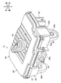
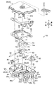
ハウジング20は、図2に示すように、樹脂製の箱体であり、前面34aからロックピン50が突出している。ハウジング20は、図3に示すように、内部空間が収容空間31になるハウジングロア30と、ハウジングロア30の開口部32を閉塞するハウジングアッパー40と、を備えている。ハウジングロア30とハウジングアッパー40とを組み合わせることで、ハウジング20内に収容空間31が形成される。
ハウジングロア30は、上面に開口部32が形成された箱状の部材である。ハウジングロア30は、平板状の底部33と、底部33の外周縁部に立設された周壁部34と、を有している。周壁部34は収容空間31を囲む枠であり、平面視で略四角形に形成されている。
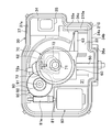
底部33は、平面視で略四角形に形成されている(図4参照)。底部33の右後部には、雄コネクタ35が下方に向けて突出している。雄コネクタ35には、駆動機構に電力を供給するための雌コネクタ(図示せず)が装着される。雌コネクタは、車両1(図1参照)に搭載された制御装置(図示せず)に電気的に接続される。
底部33は、平面視で略四角形に形成されている(図4参照)。底部33の右後部には、雄コネクタ35が下方に向けて突出している。雄コネクタ35には、駆動機構に電力を供給するための雌コネクタ(図示せず)が装着される。雌コネクタは、車両1(図1参照)に搭載された制御装置(図示せず)に電気的に接続される。
ハウジングロア30の周壁部34の前面34aには、充電口2aの壁部2b(図1参照)の内面に取り付けられる取付部36aが突設されている。また、ハウジングロア30の下面には、受電コネクタ3(図1参照)に取り付けられる左右二つのハウジング支持部36bが形成されている。
ハウジングロア30の開口縁部37(周壁部34の上端縁部)は、周壁部34の外面よりも外側にフランジ状に突出している。開口縁部37の上面には、無端状のシール部材(図示せず)が嵌め込まれるシール溝37aが全周に亘って形成されている(図4参照)。
ハウジングアッパー40は、ハウジングロア30の開口部32を閉塞するための平板状の蓋部材である。ハウジングアッパー40の外周形状は、ハウジングロア30の開口縁部37の外周形状と同じ形状に形成されている。
ハウジングアッパー40の外周縁部は、ハウジングロア30の開口縁部37に係合されるとともに、ホットメルト等の接着材によって開口縁部37に接着される。
また、ハウジングロア30の開口縁部37に設けられたシール部材(図示せず)によって、ハウジングロア30とハウジングアッパー40との間が液密にシールされる。
ハウジングアッパー40の外周縁部は、ハウジングロア30の開口縁部37に係合されるとともに、ホットメルト等の接着材によって開口縁部37に接着される。
また、ハウジングロア30の開口縁部37に設けられたシール部材(図示せず)によって、ハウジングロア30とハウジングアッパー40との間が液密にシールされる。
ロックピン50は、円形断面の軸部材であり、軸方向が前後方向に配置されている。ロックピン50の前端部は半球面に形成されている。
図4に示すように、ロックピン50の後部は、ハウジングロア30の収容空間31に収容され、ロックピン50の前部は、周壁部34の前面34aから外側に突出している。
図4に示すように、ロックピン50の後部は、ハウジングロア30の収容空間31に収容され、ロックピン50の前部は、周壁部34の前面34aから外側に突出している。
ハウジングロア30の収容空間31には、図3に示すように、ロックピン50を保持するホルダ60と、カム73が突設されたカムギヤ72を有するカム部材70と、が収容される。さらに、収容空間31には、電動モータ80と、電動モータ80の出力軸81とカムギヤ72との間に介設される駆動伝達部材90と、ロックピン50の位置を検出するスイッチ110と、電動モータ80およびスイッチ110が電気的に接続されている基板100と、が収容される。
カム部材70は、ホルダ60を前後方向に移動させるための部材である。カム部材70は、軸方向が上下方向に配置された回転軸71と、回転軸71を中心軸とする平歯車であるカムギヤ72と、カムギヤ72の下面に突設されたカム73と、を備えている。カム53は、カムギヤ72の回転中心に対して偏心している。
回転軸71の下部は、後記するカム収容枠62内に挿通されている(図4参照)。回転軸71の上下端部は、ハウジングアッパー40の下面40b(図5(a)参照)およびハウジングロア30の底面33aに回転自在に支持される。回転軸71の上端部は、ハウジングアッパー40の貫通穴を通じて外部に突出する。
また、カムギヤ72には、外方に突出したロッド72aが形成されている(図4参照)。ロッド72aは後記する進出側のスイッチ110(図3参照)の検出部を押し込む部位である。
回転軸71の下部は、後記するカム収容枠62内に挿通されている(図4参照)。回転軸71の上下端部は、ハウジングアッパー40の下面40b(図5(a)参照)およびハウジングロア30の底面33aに回転自在に支持される。回転軸71の上端部は、ハウジングアッパー40の貫通穴を通じて外部に突出する。
また、カムギヤ72には、外方に突出したロッド72aが形成されている(図4参照)。ロッド72aは後記する進出側のスイッチ110(図3参照)の検出部を押し込む部位である。
電動モータ80は、モータハウジング82から出力軸81が突出している。出力軸81には円筒状のねじ歯車81aが外嵌される。
駆動伝達部材90は、軸方向が上下方向に配置された回転軸91と、回転軸91を中心軸とするはすば歯車である下部ギヤ92と、回転軸91を中心軸とする平歯車である上部ギヤ93と、を備えている。
回転軸91の上下端部は、ハウジングアッパー40の下面40b(図5(a)参照)およびハウジングロア30の底面33aに回転自在に支持される。
図4に示すように、下部ギヤ92は電動モータ80のねじ歯車81aに連結される。また、上部ギヤ93はカムギヤ72に連結される。
回転軸91の上下端部は、ハウジングアッパー40の下面40b(図5(a)参照)およびハウジングロア30の底面33aに回転自在に支持される。
図4に示すように、下部ギヤ92は電動モータ80のねじ歯車81aに連結される。また、上部ギヤ93はカムギヤ72に連結される。
電動モータ80のねじ歯車81aを回転させると、その駆動力が下部ギヤ92に伝達され、駆動伝達部材90が軸回りに回転する。これにより、上部ギヤ93からカムギヤ72に駆動力が伝達される。そして、カムギヤ72が軸回りに回転することで、カム73が回転軸71の軸回りに回転するように構成されている。
ホルダ60は、ハウジングロア30の底面33a上に前後方向に移動自在に取り付けられている。
ホルダ60の前端面にロックピン50の後部が取り付けられ、ホルダ60の後部にはカム73が収容されるカム収容枠62が開口している。
カム収容枠62は、上下方向に開口しており、上側からカム73が挿入される。カム収容枠62の内周面は、カム73が当接するカム受け面となっている。
また、ホルダ60の前部には、右側に向けて突出したロッド63が形成されている。ロッド63は後記する退行側のスイッチ110(図3参照)の検出部を押し込む部位である。
ホルダ60の前端面にロックピン50の後部が取り付けられ、ホルダ60の後部にはカム73が収容されるカム収容枠62が開口している。
カム収容枠62は、上下方向に開口しており、上側からカム73が挿入される。カム収容枠62の内周面は、カム73が当接するカム受け面となっている。
また、ホルダ60の前部には、右側に向けて突出したロッド63が形成されている。ロッド63は後記する退行側のスイッチ110(図3参照)の検出部を押し込む部位である。
基板100は、図2に示すように、左右方向に幅広に形成され、電動モータ80およびホルダ60の上方に配置される。
基板100は、電動モータ80の駆動を制御するものである。基板100には、電動モータ80、スイッチ110および雄コネクタ35が電気的に接続されている。
基板100は、電動モータ80の駆動を制御するものである。基板100には、電動モータ80、スイッチ110および雄コネクタ35が電気的に接続されている。
スイッチ110は、基板100の下面に取り付けられている。第一実施形態では、二つのスイッチ110,110が左右方向に並設されている。各スイッチ110,110は、カムギヤ72のロッド72aおよびホルダ60のロッド63の移動領域の上方にそれぞれ配置されている。
第一実施形態のアクチュエータ10では、図4に示すように、電動モータ80のねじ歯車81aが回転すると、その駆動力が駆動伝達部材90を介してカムギヤ72に伝達される。
そして、カムギヤ72が回転することで、カム73が前方または後方に向けて回転移動し、カム73によってカム収容枠62の内周面が前方または後方に押し出される。
これにより、ホルダ60およびロックピン50が前方または後方に移動し、ハウジング20に対するロックピン50の突出量が増減する。
そして、カムギヤ72が回転することで、カム73が前方または後方に向けて回転移動し、カム73によってカム収容枠62の内周面が前方または後方に押し出される。
これにより、ホルダ60およびロックピン50が前方または後方に移動し、ハウジング20に対するロックピン50の突出量が増減する。
ホルダ60が前方に移動したときに、カムギヤ72のロッド72aによって進出側のスイッチ110(図3参照)の検出部が押し込まれると、進出側のスイッチ110から制御装置(図示せず)に検出信号が出力され、出力軸81の回転が停止する。
また、ホルダ60が後方に移動したときに、ホルダ60のロッド63によって退行側のスイッチ110(図3参照)の検出部が押し込まれると、退行側のスイッチ110から制御装置に検出信号が出力され、出力軸81の回転が停止する。
また、ホルダ60が後方に移動したときに、ホルダ60のロッド63によって退行側のスイッチ110(図3参照)の検出部が押し込まれると、退行側のスイッチ110から制御装置に検出信号が出力され、出力軸81の回転が停止する。
図1に示すように、受電コネクタ3に充電コネクタ4が装着されたことを制御装置(図示せず)が検出した場合には、ロックピン50がハウジング20に対して進出し、ロックピン50の前部が充電コネクタ4のフック4bの上方に配置される。
これにより、フック4bの傾動がロックピン50によって規制され、フック4bは受電コネクタ3の係合突起3bに係合した状態に固定される。これにより、受電コネクタ3から充電コネクタ4が外れるのを防ぐことができる。
そして、ロックピン50の進出が停止した後に、充電装置(図示せず)から蓄電池(図示せず)への充電が開始される。
これにより、フック4bの傾動がロックピン50によって規制され、フック4bは受電コネクタ3の係合突起3bに係合した状態に固定される。これにより、受電コネクタ3から充電コネクタ4が外れるのを防ぐことができる。
そして、ロックピン50の進出が停止した後に、充電装置(図示せず)から蓄電池(図示せず)への充電が開始される。
また、充電後にロック解除信号が制御装置(図示せず)に入力されると、ロックピン50がハウジング20に対して退行し、ロックピン50の前部が充電コネクタ4のフック4bの上方から退去する。
これにより、フック4bが傾動可能となり、フック4bを受電コネクタ3の係合突起3bから離脱させて、受電コネクタ3から充電コネクタ4を引き抜くことができる。
これにより、フック4bが傾動可能となり、フック4bを受電コネクタ3の係合突起3bから離脱させて、受電コネクタ3から充電コネクタ4を引き抜くことができる。
また、図3に示すように、ハウジングアッパー40の上面には、カム部材70の回転軸71の上端部に取り付けられたロック解除用レバー42が設けられている(図2参照)。ロック解除用レバー42を回転させることで、カム部材70を手動で強制的に回転させ、ロックピン50を退行させることができる。
次に、第一実施形態のアクチュエータ10に設けられた遮蔽壁210、空気穴220、仕切り壁230および蓋部240について説明する。
アクチュエータ10には、図5(a)および(b)に示すように、ハウジングロア30の底面33aに立設された遮蔽壁210と、ハウジングロア30の周壁部34を貫通している空気穴220と、ハウジングアッパー40の下面40bに形成された仕切り壁230と、ハウジングアッパー40の外周縁部に形成された蓋部240と、が形成されている。空気穴220は、周壁部34および遮蔽壁210に囲まれた内部空間210aに連通している。
アクチュエータ10には、図5(a)および(b)に示すように、ハウジングロア30の底面33aに立設された遮蔽壁210と、ハウジングロア30の周壁部34を貫通している空気穴220と、ハウジングアッパー40の下面40bに形成された仕切り壁230と、ハウジングアッパー40の外周縁部に形成された蓋部240と、が形成されている。空気穴220は、周壁部34および遮蔽壁210に囲まれた内部空間210aに連通している。
遮蔽壁210は、図4に示すように、ハウジングロア30の底面33aの右側前部に立設された平面視でL形状の壁である。遮蔽壁210の両側縁部は、周壁部34の内面に接続されており、周壁部34および遮蔽壁210によって、図5(b)に示すように、平面視で前後方向に幅広な長方形の内部空間210aが形成されている。
これにより、ハウジングロア30の底部33において、収容空間31側の内面である底面33aは、遮蔽壁210によって、周壁部34および遮蔽壁210によって囲まれた領域と、それ以外の領域とに仕切られている。
これにより、ハウジングロア30の底部33において、収容空間31側の内面である底面33aは、遮蔽壁210によって、周壁部34および遮蔽壁210によって囲まれた領域と、それ以外の領域とに仕切られている。
内部空間210aは、周壁部34の前壁34bおよび右側壁34cの一部と、遮蔽壁210を構成する後側内壁211および左側内壁212と、によって囲まれた空間であり、内部空間210aの上面は開口している。
後側内壁211は、前壁34bの内面に沿って形成されている。また、左側内壁212は、右側壁34cの内面に沿って形成されている。図5(a)に示すように、左側内壁212よりも後側内壁211が高く形成されている。
後側内壁211は、前壁34bの内面に沿って形成されている。また、左側内壁212は、右側壁34cの内面に沿って形成されている。図5(a)に示すように、左側内壁212よりも後側内壁211が高く形成されている。
空気穴220は、図5(b)に示すように、周壁部34の右側壁34cの前部に形成された円形断面の貫通穴である。空気穴220は、周壁部34の外面から内面に亘って貫通している。空気穴220の内側開口部220aは、左側内壁212の上端縁部よりも底面33a側となる位置(高さ)に形成されている。
空気穴220は、図1に示すように、ハウジングロア30が傾斜した状態で受電コネクタ3に取り付けられたときには、ハウジングロア30の高い位置に配置される。
空気穴220は、図1に示すように、ハウジングロア30が傾斜した状態で受電コネクタ3に取り付けられたときには、ハウジングロア30の高い位置に配置される。
図6(a)に示すように、周壁部34の外面において、空気穴220の外側開口部220bの周囲には、側面視でU形状の凸壁250が突設されている。
凸壁250の下部には、水抜き用および通気用の切り欠き部251が形成されている。凸壁250は、切り欠き部251を境にして、前側凸壁252と後側凸壁253とに分割されている。図5(b)に示すように、後側凸壁253の突出量(高さ)は、前側凸壁252よりも小さい。
凸壁250の下部には、水抜き用および通気用の切り欠き部251が形成されている。凸壁250は、切り欠き部251を境にして、前側凸壁252と後側凸壁253とに分割されている。図5(b)に示すように、後側凸壁253の突出量(高さ)は、前側凸壁252よりも小さい。
切り欠き部251は、図1に示すように、ハウジングロア30が傾斜した状態で受電コネクタ3に取り付けられたときに、凸壁250の最下部に配置されるように配置されている。これにより、アクチュエータ10を受電コネクタ3に取り付けたときに、凸壁250内の水抜きに最適な位置に切り欠き部251が配置されることになる。
空気穴220の外側開口部220bは、円形の透湿防水素材221によって覆われている(図6(a)参照)。
透湿防水素材221は、空気の出入りを許容しつつ水の出入りを阻止する素材であり、外部空間から空気穴220に水や埃が浸入するのを防ぐことができる。
透湿防水素材221は、図6(a)に示すように、外側開口部220bよりも大径に形成されている。透湿防水素材221は、周壁部34の外面において、凸壁250に囲まれた領域に、両面テープ等の接着手段によって貼り付けられている。
透湿防水素材221は、空気の出入りを許容しつつ水の出入りを阻止する素材であり、外部空間から空気穴220に水や埃が浸入するのを防ぐことができる。
透湿防水素材221は、図6(a)に示すように、外側開口部220bよりも大径に形成されている。透湿防水素材221は、周壁部34の外面において、凸壁250に囲まれた領域に、両面テープ等の接着手段によって貼り付けられている。
作業者の指先で透湿防水素材221を外側開口部220bの周囲に貼り付けるときには、凸壁250に囲まれた領域に指先を入り込ませる必要がある。凸壁250では、突出量(高さ)が小さい後側凸壁253側から前記領域に指先をスムーズに入り込ませることができる(図5(b)参照)。したがって、外側開口部220bの周囲に透湿防水素材221を確実に押し付けることができる。
仕切り壁230は、図5(a)に示すように、ハウジングアッパー40の下面40bから下方に向けて突設された平板状の壁である。仕切り壁230は、前後方向に幅広に形成されており(図5(b)参照)、遮蔽壁210の側面に対向して配置される側面を有している。
ハウジングアッパー40をハウジングロア30に組み付けたときに、仕切り壁230の下部は、周壁部34および遮蔽壁210によって囲まれた内部空間210aに挿入される。そして、仕切り壁230の下部は、左側内壁212の内面および空気穴220の内側開口部220aに対向して配置される(図5(b)参照)。このように、仕切り壁230と左側内壁212とが高さ方向にオーバーラップし、仕切り壁230の下部が周壁部34および遮蔽壁210に囲まれた状態となる。
ハウジングアッパー40をハウジングロア30に組み付けたときに、仕切り壁230の下部は、周壁部34および遮蔽壁210によって囲まれた内部空間210aに挿入される。そして、仕切り壁230の下部は、左側内壁212の内面および空気穴220の内側開口部220aに対向して配置される(図5(b)参照)。このように、仕切り壁230と左側内壁212とが高さ方向にオーバーラップし、仕切り壁230の下部が周壁部34および遮蔽壁210に囲まれた状態となる。
また、仕切り壁230は、空気穴220の内側開口部220aよりも幅広に形成されるとともに(図5(b)参照)、仕切り壁230の下端縁部は、内側開口部220aよりも底面33a側に配置される。すなわち、空気穴220の内側開口部220aが仕切り壁230によって覆われた状態となる。
ハウジングアッパー40をハウジングロア30に組み付けた状態では、遮蔽壁210の上端縁部とハウジングアッパー40の下面40bとの間に隙間が形成される。また、仕切り壁230と遮蔽壁210との間に隙間が形成される。さらに、仕切り壁230の下端縁部と底面33aとの間に隙間が形成される。
図2および図3に示すように、ハウジングアッパー40の外周縁部の右側前部には、下方に向けて突出した板状の蓋部240が形成されている。
蓋部240は、図5(a)に示すように、ハウジングアッパー40をハウジングロア30に組み付けたときに、外側開口部220bおよび凸壁250に対向して配置される。また、蓋部240は、図5(b)に示すように、前縁部から後縁部に向かうに従って、周壁部34の外面に近づくように傾斜している。
蓋部240は、図5(a)に示すように、ハウジングアッパー40をハウジングロア30に組み付けたときに、外側開口部220bおよび凸壁250に対向して配置される。また、蓋部240は、図5(b)に示すように、前縁部から後縁部に向かうに従って、周壁部34の外面に近づくように傾斜している。
蓋部240の前縁部には前側リブ241が形成されている。また、蓋部240の後縁部には後側リブ242が形成されている。前側リブ241および後側リブ242は、互いに平行で上下方向に延設されている。
前側リブ241は、前側凸壁252に外側から接する部位である。後側リブ242は、後側凸壁253に外側から接する部位である。前側リブ241は、後側リブ242よりも突出量が大きく形成されており、前側凸壁252と前側リブ241とのラップ量が大きくなっている。
前側リブ241は、前側凸壁252に外側から接する部位である。後側リブ242は、後側凸壁253に外側から接する部位である。前側リブ241は、後側リブ242よりも突出量が大きく形成されており、前側凸壁252と前側リブ241とのラップ量が大きくなっている。
このようなハウジング20では、図5(a)に示すように、収容空間31から仕切り壁230と遮蔽壁210との隙間および空気穴220を通じて外部空間に至る通気路が形成される。この通気路を通じてハウジング20の内外を通気させることができる。
以上のようなアクチュエータ10では、図5(a)に示すように、ハウジングロア30にハウジングアッパー40を組み付けたときに、遮蔽壁210に仕切り壁230がオーバーラップする。これにより、収容空間31から空気穴220に至るラビリンス形状(収容空間31側から空気穴220の内側開口部220aが見通せない形状)の通気路が形成される。
このように、収容空間31から空気穴220に至る通気路がラビリンス形状になるとともに、図5(b)に示すように、仕切り壁230と左側内壁212との隙間が全体的に狭くなっているため、空気穴220にグリースが流入し難くなる。したがって、空気穴220を通じてハウジング20の内外を確実に通気させることができ、ハウジング20の内外の気圧差を抑えることができる。
このように、収容空間31から空気穴220に至る通気路がラビリンス形状になるとともに、図5(b)に示すように、仕切り壁230と左側内壁212との隙間が全体的に狭くなっているため、空気穴220にグリースが流入し難くなる。したがって、空気穴220を通じてハウジング20の内外を確実に通気させることができ、ハウジング20の内外の気圧差を抑えることができる。
また、空気穴220の外側開口部220bが透湿防水素材221によって塞がれているため、外部空間から水や埃が空気穴220を通過するのを防ぎつつ、空気穴220を通じてハウジング20の内外を通気させることができる。
また、空気穴220にグリースが流入し難くなっているため、透湿防水素材221がグリースによって目詰まりするのを防ぐことができる。
また、空気穴220にグリースが流入し難くなっているため、透湿防水素材221がグリースによって目詰まりするのを防ぐことができる。
また、図5(a)に示すように、空気穴220の外側開口部220bに対向して蓋部240が配置されるため、透湿防水素材221が外部に露出するのを防ぐことができるとともに、外部から透湿防水素材221に水や埃が付着するのを防ぐことができる。
また、周壁部34の外面において、空気穴220の外側開口部220bの周囲に形成された後側凸壁253は、前側凸壁252よりも突出量(高さ)が小さく形成されている。
作業者の指先で透湿防水素材221を外側開口部220bの周囲に貼り付けるときには、凸壁250に囲まれた領域に指先を入り込ませる必要がある。このとき、突出量(高さ)が小さい後側凸壁253側から前記領域に指先をスムーズに入り込ませることができるため(図5(b)参照)、外側開口部220bの周囲に透湿防水素材221を確実に押し付けることができる。
作業者の指先で透湿防水素材221を外側開口部220bの周囲に貼り付けるときには、凸壁250に囲まれた領域に指先を入り込ませる必要がある。このとき、突出量(高さ)が小さい後側凸壁253側から前記領域に指先をスムーズに入り込ませることができるため(図5(b)参照)、外側開口部220bの周囲に透湿防水素材221を確実に押し付けることができる。
また、突出量が大きい前側凸壁252が車両の前方側に配置され、突出量が小さい後側凸壁253が車両の後方側に配置されている。さらに、蓋部240においても、突出量が大きい前側リブ241が車両の前方側に配置され、突出量が小さい後側リブ242が車両の後方側に配置されている。この構成では、前側凸壁252と前側リブ241とのラップ量が大きくなるため、車両前方からの走行風や雨水を、前側凸壁252および前側リブ241によって遮ることができる。
以上、本発明の第一実施形態について説明したが、本発明は前記実施形態に限定されることなく、その趣旨を逸脱しない範囲で適宜に変更が可能である。
例えば、第一実施形態では、図5(a)に示すように、仕切り壁230が遮蔽壁210の内面に対向しているが、仕切り壁230が遮蔽壁210の外面に対向するように構成してもよい。
例えば、第一実施形態では、図5(a)に示すように、仕切り壁230が遮蔽壁210の内面に対向しているが、仕切り壁230が遮蔽壁210の外面に対向するように構成してもよい。
また、第一実施形態では、図5(b)に示すように、周壁部34および遮蔽壁210に囲まれた内部空間210aが形成されているが、筒状の遮蔽壁を底面33aに立設し、この遮蔽壁に囲まれた内部空間を形成してもよい。
また、第一実施形態では、空気穴220の外側開口部220bを透湿防水素材221によって塞いでいるが、空気穴220の内側開口部220aを透湿防水素材221によって塞いでもよい。
また、透湿防水素材221の材質は限定されるものではなく、空気の出入りを許容しつつ水や塵の出入りを阻止する網状の部材であればよい。
また、透湿防水素材221の材質は限定されるものではなく、空気の出入りを許容しつつ水や塵の出入りを阻止する網状の部材であればよい。
また、遮蔽壁210、空気穴220および仕切り壁230の位置や形状は限定されるものではなく、収容空間31内の駆動機構のレイアウト等に対応させて適宜に設定することができる。
例えば、図4に示したモータハウジング82を囲むように遮蔽壁を形成し、ハウジングロア30の側壁部34または底部33に遮蔽壁内に連通する空気穴を形成するとともに、ハウジングアッパー40の内面に仕切り壁を形成してもよい。この構成では、発熱する電動モータ80の近傍に空気穴が配置されるため、ハウジング20の内外の気圧差を効果的に抑えることができる。
例えば、図4に示したモータハウジング82を囲むように遮蔽壁を形成し、ハウジングロア30の側壁部34または底部33に遮蔽壁内に連通する空気穴を形成するとともに、ハウジングアッパー40の内面に仕切り壁を形成してもよい。この構成では、発熱する電動モータ80の近傍に空気穴が配置されるため、ハウジング20の内外の気圧差を効果的に抑えることができる。
また、第一実施形態では、図1に示すように、受電コネクタ3から充電コネクタ4が外れるのを防ぐためのロック機構5に、本発明のアクチュエータを適用しているが、本発明のアクチュエータは各種のアクチュエータに適用可能である。
[第二実施形態]
次に、第二実施形態のアクチュエータについて説明する。
第二実施形態のアクチュエータは、図7(a)に示すように、ハウジングロア30の底部33に空気穴220が形成されている点が、前記した第一実施形態のアクチュエータ10(図3参照)と異なっている。
次に、第二実施形態のアクチュエータについて説明する。
第二実施形態のアクチュエータは、図7(a)に示すように、ハウジングロア30の底部33に空気穴220が形成されている点が、前記した第一実施形態のアクチュエータ10(図3参照)と異なっている。
第二実施形態のアクチュエータには、ハウジングロア30の底面33aに立設された遮蔽壁260と、ハウジングロア30の底部33を貫通している空気穴220と、ハウジングアッパー40の下面40bに形成された仕切り壁270と、が形成されている。空気穴220は、周壁部34および遮蔽壁260に囲まれた内部空間260aに連通している。
遮蔽壁260は、図7(b)に示すように、ハウジングロア30の底面33aの後部に立設された平面視でU形状の壁である。遮蔽壁260の両側縁部は、周壁部34の内面に接続されている。そして、周壁部34および遮蔽壁260によって、平面視で略半円形状の内部空間260aが形成されている。また、内部空間260aの上面は開口している。
第二実施形態では、図7(a)に示すように、遮蔽壁260の上端縁部が、周壁部34の上端縁部よりも僅かに下方の位置に配置されている。
第二実施形態の遮蔽壁260は、底面33aの後部に形成されているため、アクチュエータ10を受電コネクタ3に取り付けたときに(図1参照)、遮蔽壁260が底面33aの低い位置に配置されることになる。このように、遮蔽壁260はグリースが溜まり易い位置に配置されているため、遮蔽壁260の高さを大きくすることで、グリースを確実に遮るように構成されている。
第二実施形態の遮蔽壁260は、底面33aの後部に形成されているため、アクチュエータ10を受電コネクタ3に取り付けたときに(図1参照)、遮蔽壁260が底面33aの低い位置に配置されることになる。このように、遮蔽壁260はグリースが溜まり易い位置に配置されているため、遮蔽壁260の高さを大きくすることで、グリースを確実に遮るように構成されている。
底部33の後部には、周壁部34および遮蔽壁260に囲まれた内部空間260aに連通する空気穴220が貫通している。また、空気穴220の外側開口部220bは、透湿防水素材221によって覆われている。
仕切り壁270は、ハウジングアッパー40の下面40bから下方に向けて突設された軸断面がU形状の壁である(図7(b)参照)。
ハウジングアッパー40をハウジングロア30に組み付けたときに、仕切り壁270は遮蔽壁260の外側に配置され、仕切り壁270と遮蔽壁260とが高さ方向にオーバーラップした状態となる。また、仕切り壁270は、図7(b)に示すように、遮蔽壁260の外面に沿って配置され、遮蔽壁260の外面に一定の間隔を空けて対向している。
ハウジングアッパー40をハウジングロア30に組み付けたときに、仕切り壁270は遮蔽壁260の外側に配置され、仕切り壁270と遮蔽壁260とが高さ方向にオーバーラップした状態となる。また、仕切り壁270は、図7(b)に示すように、遮蔽壁260の外面に沿って配置され、遮蔽壁260の外面に一定の間隔を空けて対向している。
また、ハウジングアッパー40をハウジングロア30に組み付けた状態では、図7(a)に示すように、仕切り壁270の下端縁部と底面33aとの間に隙間が形成される。また、仕切り壁270と遮蔽壁260との間に隙間が形成される。さらに、遮蔽壁260の上端縁部とハウジングアッパー40の下面40bとの間に隙間が形成される。
このように、収容空間31から仕切り壁270と遮蔽壁260との隙間および空気穴220を通じて外部空間に至るラビリンス形状の通気路が形成される。これにより、収容空間31から空気穴220にグリースが流入し難くなる。したがって、空気穴220を通じてハウジング20の内外を確実に通気させることができ、ハウジング20の内外の気圧差を抑えることができる。
また、第二実施形態では、仕切り壁270が収容空間31の後部に収容された駆動伝達部材90の下部ギヤ92および上部ギヤ93と、遮蔽壁260との間に配置される。したがって、駆動伝達部材90が回転したときに、下部ギヤ92および上部ギヤ93から飛散するグリースを仕切り壁270によって遮ることができる。
1 車両
2 車体
2a 充電口
3 受電コネクタ
4 充電コネクタ
4b フック
5 ロック機構
10 アクチュエータ
20 ハウジング
30 ハウジングロア
31 収容空間
33 底部
34 周壁部
40 ハウジングアッパー
50 ロックピン
60 ホルダ
70 カム部材
72 カムギヤ
73 カム
80 電動モータ
82 モータハウジング
90 駆動伝達部材
100 基板
210 遮蔽壁(第一実施形態)
210a 内部空間
211 左側内壁
212 後側内壁
220 空気穴
220a 内側開口部
220b 外側開口部
221 透湿防水素材
230 仕切り壁(第一実施形態)
240 蓋部
241 前側リブ
242 後側リブ
250 凸壁
251 切り欠き部
252 前側凸壁
253 後側凸壁
260 遮蔽壁(第二実施形態)
260a 内部空間(第二実施形態)
270 仕切り壁(第二実施形態)
2 車体
2a 充電口
3 受電コネクタ
4 充電コネクタ
4b フック
5 ロック機構
10 アクチュエータ
20 ハウジング
30 ハウジングロア
31 収容空間
33 底部
34 周壁部
40 ハウジングアッパー
50 ロックピン
60 ホルダ
70 カム部材
72 カムギヤ
73 カム
80 電動モータ
82 モータハウジング
90 駆動伝達部材
100 基板
210 遮蔽壁(第一実施形態)
210a 内部空間
211 左側内壁
212 後側内壁
220 空気穴
220a 内側開口部
220b 外側開口部
221 透湿防水素材
230 仕切り壁(第一実施形態)
240 蓋部
241 前側リブ
242 後側リブ
250 凸壁
251 切り欠き部
252 前側凸壁
253 後側凸壁
260 遮蔽壁(第二実施形態)
260a 内部空間(第二実施形態)
270 仕切り壁(第二実施形態)
Claims (8)
- 下側のハウジングロアと上側のハウジングアッパーとを組み合わせることで、駆動機構が収容される収容空間が形成されるアクチュエータであって、
前記ハウジングロアの底面に遮蔽壁が立設され、
前記ハウジングロアには、前記遮蔽壁に囲まれた空間に連通する空気穴が貫通しており、
前記ハウジングアッパーの内面には、前記遮蔽壁の側面に対向して配置される仕切り壁が形成されていることを特徴とするアクチュエータ。 - 前記空気穴は、前記ハウジングロアの周壁部に形成されていることを特徴とする請求の範囲第1項に記載のアクチュエータ。
- 前記空気穴は、前記ハウジングロアの底部に形成されていることを特徴とする請求の範囲第1項に記載のアクチュエータ。
- 前記空気穴は、空気の出入りを許容しつつ水の出入りを阻止する透湿防水素材によって塞がれていることを特徴とする請求の範囲第1項から請求の範囲第3項のいずれか一項に記載のアクチュエータ。
- 前記ハウジングアッパーには、蓋部が形成されており、
前記蓋部は、前記ハウジングロアの外面に形成された前記空気穴の外側開口部に対向して配置されていることを特徴とする請求の範囲第4項に記載のアクチュエータ。 - 前記空気穴の前記外側開口部が前記透湿防水素材によって塞がれており、
前記ハウジングロアの外面において、前記外側開口部の周囲には凸壁が突設され、
前記蓋部は、前記外側開口部および前記凸壁に対向して配置されており、
前記凸壁の一部に、他の部位よりも突出量が小さい部位が形成されていることを特徴とする請求の範囲第5項に記載のアクチュエータ。 - 前記仕切り壁は、前記遮蔽壁の側面に沿って形成されていることを特徴とする請求の範囲第1項から請求の範囲第3項のいずれか一項に記載のアクチュエータ。
- 前記仕切り壁は、前記収容空間に収容されたギヤと前記遮蔽壁との間に配置されていることを特徴とする請求の範囲第1項から請求の範囲第3項のいずれか一項に記載のアクチュエータ。
Priority Applications (1)
| Application Number | Priority Date | Filing Date | Title |
|---|---|---|---|
| CN201380006099.XA CN104067485B (zh) | 2012-12-03 | 2013-12-03 | 驱动器 |
Applications Claiming Priority (2)
| Application Number | Priority Date | Filing Date | Title |
|---|---|---|---|
| JP2012264131A JP6175230B2 (ja) | 2012-12-03 | 2012-12-03 | アクチュエータ |
| JP2012-264131 | 2012-12-03 |
Publications (1)
| Publication Number | Publication Date |
|---|---|
| WO2014087997A1 true WO2014087997A1 (ja) | 2014-06-12 |
Family
ID=50883415
Family Applications (1)
| Application Number | Title | Priority Date | Filing Date |
|---|---|---|---|
| PCT/JP2013/082470 Ceased WO2014087997A1 (ja) | 2012-12-03 | 2013-12-03 | アクチュエータ |
Country Status (3)
| Country | Link |
|---|---|
| JP (1) | JP6175230B2 (ja) |
| CN (1) | CN104067485B (ja) |
| WO (1) | WO2014087997A1 (ja) |
Cited By (2)
| Publication number | Priority date | Publication date | Assignee | Title |
|---|---|---|---|---|
| DE102019126087A1 (de) * | 2019-09-27 | 2021-04-01 | Kiekert Aktiengesellschaft | Elektrische Ladevorrichtung eines Kraftfahrzeuges |
| JP2023030682A (ja) * | 2021-08-23 | 2023-03-08 | 株式会社ミクニ | 電動装置 |
Families Citing this family (6)
| Publication number | Priority date | Publication date | Assignee | Title |
|---|---|---|---|---|
| JP6811127B2 (ja) | 2017-03-17 | 2021-01-13 | 株式会社村上開明堂 | アクチュエータ |
| JP6811129B2 (ja) * | 2017-03-17 | 2021-01-13 | 株式会社村上開明堂 | アクチュエータの設置構造 |
| JP6871292B2 (ja) * | 2019-03-11 | 2021-05-12 | 矢崎総業株式会社 | 樹脂構造体 |
| JP7272305B2 (ja) * | 2020-03-19 | 2023-05-12 | 株式会社デンソー | アクチュエータのブリーザ構造 |
| KR102740840B1 (ko) * | 2022-08-09 | 2024-12-12 | 디젠스 주식회사 | 전기차용 잠금장치와 이것이 구비된 전기차용 스마트인렛 |
| JP2024095455A (ja) * | 2022-12-28 | 2024-07-10 | ニデック株式会社 | モータユニットおよび駆動装置 |
Citations (3)
| Publication number | Priority date | Publication date | Assignee | Title |
|---|---|---|---|---|
| WO2007046161A1 (ja) * | 2005-10-21 | 2007-04-26 | Kabushiki Kaisha Yaskawa Denki | 円筒形リニアモータ |
| JP2007143208A (ja) * | 2005-11-14 | 2007-06-07 | Mitsuba Corp | モータの製造方法 |
| JP2010280245A (ja) * | 2009-06-02 | 2010-12-16 | Jtekt Corp | 車両用操舵装置 |
Family Cites Families (8)
| Publication number | Priority date | Publication date | Assignee | Title |
|---|---|---|---|---|
| JPS6246744A (ja) * | 1985-08-26 | 1987-02-28 | Nissan Motor Co Ltd | ワイパ−モ−タ |
| JPH04118757U (ja) * | 1991-03-29 | 1992-10-23 | アイシン精機株式会社 | アクチユエータ装置 |
| JP2007329995A (ja) * | 2006-06-06 | 2007-12-20 | Asmo Co Ltd | モータ |
| JP5044164B2 (ja) * | 2006-08-11 | 2012-10-10 | 株式会社ミツバ | モータ装置 |
| JP5014030B2 (ja) * | 2007-09-07 | 2012-08-29 | 株式会社ミツバ | 減速機構付き電動モータ |
| CN201435694Y (zh) * | 2009-02-24 | 2010-03-31 | 泰科电子(上海)有限公司 | 用于薄膜太阳能电池的接线盒 |
| CN201839120U (zh) * | 2010-09-24 | 2011-05-18 | 比亚迪股份有限公司 | 一种电机结构 |
| CN202183670U (zh) * | 2011-08-19 | 2012-04-04 | 成都华川电装有限责任公司 | 电机透气结构 |
-
2012
- 2012-12-03 JP JP2012264131A patent/JP6175230B2/ja active Active
-
2013
- 2013-12-03 WO PCT/JP2013/082470 patent/WO2014087997A1/ja not_active Ceased
- 2013-12-03 CN CN201380006099.XA patent/CN104067485B/zh not_active Expired - Fee Related
Patent Citations (3)
| Publication number | Priority date | Publication date | Assignee | Title |
|---|---|---|---|---|
| WO2007046161A1 (ja) * | 2005-10-21 | 2007-04-26 | Kabushiki Kaisha Yaskawa Denki | 円筒形リニアモータ |
| JP2007143208A (ja) * | 2005-11-14 | 2007-06-07 | Mitsuba Corp | モータの製造方法 |
| JP2010280245A (ja) * | 2009-06-02 | 2010-12-16 | Jtekt Corp | 車両用操舵装置 |
Cited By (3)
| Publication number | Priority date | Publication date | Assignee | Title |
|---|---|---|---|---|
| DE102019126087A1 (de) * | 2019-09-27 | 2021-04-01 | Kiekert Aktiengesellschaft | Elektrische Ladevorrichtung eines Kraftfahrzeuges |
| JP2023030682A (ja) * | 2021-08-23 | 2023-03-08 | 株式会社ミクニ | 電動装置 |
| JP7650751B2 (ja) | 2021-08-23 | 2025-03-25 | 株式会社ミクニ | 電動装置 |
Also Published As
| Publication number | Publication date |
|---|---|
| CN104067485A (zh) | 2014-09-24 |
| CN104067485B (zh) | 2017-08-29 |
| JP6175230B2 (ja) | 2017-08-02 |
| JP2014110691A (ja) | 2014-06-12 |
Similar Documents
| Publication | Publication Date | Title |
|---|---|---|
| JP6175230B2 (ja) | アクチュエータ | |
| JP4872899B2 (ja) | 充電コネクタの取付構造 | |
| KR101467712B1 (ko) | 차량용 카메라 장치 및 차량 내에 카메라 장치의 설치 방법 | |
| JP5953221B2 (ja) | アクチュエータ | |
| CN203613903U (zh) | 车辆门锁装置 | |
| WO2014045830A1 (ja) | 充電ポート構造 | |
| JP5578734B2 (ja) | 車両用ドアロック装置 | |
| JP6270047B2 (ja) | 車両のフロア構造 | |
| CN110356333B (zh) | 盖装置 | |
| CN102103879B (zh) | 托盘移动机构和车载音频设备 | |
| JP2018156826A (ja) | アクチュエータ | |
| CN105658000A (zh) | 压力补正装置及包括其的电子控制装置模块 | |
| JP6404099B2 (ja) | ドアロック装置 | |
| US12606017B2 (en) | Lid opening/closing device | |
| JP2018041210A (ja) | 自律走行車両 | |
| JP2022152814A (ja) | 車両用リッド装置 | |
| CN108621818B (zh) | 致动器 | |
| TWI436531B (zh) | 插座及具備該插座的充電裝置 | |
| JP4978342B2 (ja) | 給電ユニット | |
| JP6811129B2 (ja) | アクチュエータの設置構造 | |
| JP2022046441A (ja) | ドアラッチ装置の防水構造 | |
| KR101684077B1 (ko) | 차량용 프론트 트레이 | |
| CN219843671U (zh) | 车载摄像装置 | |
| JP2025103994A (ja) | 電子制御装置 | |
| JP2012199102A (ja) | 電子機器 |
Legal Events
| Date | Code | Title | Description |
|---|---|---|---|
| 121 | Ep: the epo has been informed by wipo that ep was designated in this application |
Ref document number: 13860594 Country of ref document: EP Kind code of ref document: A1 |
|
| NENP | Non-entry into the national phase |
Ref country code: DE |
|
| 122 | Ep: pct application non-entry in european phase |
Ref document number: 13860594 Country of ref document: EP Kind code of ref document: A1 |