WO2014080889A1 - ラジアルタービン - Google Patents
ラジアルタービン Download PDFInfo
- Publication number
- WO2014080889A1 WO2014080889A1 PCT/JP2013/081123 JP2013081123W WO2014080889A1 WO 2014080889 A1 WO2014080889 A1 WO 2014080889A1 JP 2013081123 W JP2013081123 W JP 2013081123W WO 2014080889 A1 WO2014080889 A1 WO 2014080889A1
- Authority
- WO
- WIPO (PCT)
- Prior art keywords
- nozzle
- nozzle vane
- width direction
- vane
- turbine
- Prior art date
- Legal status (The legal status is an assumption and is not a legal conclusion. Google has not performed a legal analysis and makes no representation as to the accuracy of the status listed.)
- Ceased
Links
Images





Classifications
-
- F—MECHANICAL ENGINEERING; LIGHTING; HEATING; WEAPONS; BLASTING
- F01—MACHINES OR ENGINES IN GENERAL; ENGINE PLANTS IN GENERAL; STEAM ENGINES
- F01D—NON-POSITIVE DISPLACEMENT MACHINES OR ENGINES, e.g. STEAM TURBINES
- F01D9/00—Stators
- F01D9/02—Nozzles; Nozzle boxes; Stator blades; Guide conduits, e.g. individual nozzles
-
- F—MECHANICAL ENGINEERING; LIGHTING; HEATING; WEAPONS; BLASTING
- F02—COMBUSTION ENGINES; HOT-GAS OR COMBUSTION-PRODUCT ENGINE PLANTS
- F02B—INTERNAL-COMBUSTION PISTON ENGINES; COMBUSTION ENGINES IN GENERAL
- F02B37/00—Engines characterised by provision of pumps driven at least for part of the time by exhaust
- F02B37/12—Control of the pumps
- F02B37/24—Control of the pumps by using pumps or turbines with adjustable guide vanes
-
- F—MECHANICAL ENGINEERING; LIGHTING; HEATING; WEAPONS; BLASTING
- F01—MACHINES OR ENGINES IN GENERAL; ENGINE PLANTS IN GENERAL; STEAM ENGINES
- F01D—NON-POSITIVE DISPLACEMENT MACHINES OR ENGINES, e.g. STEAM TURBINES
- F01D17/00—Regulating or controlling by varying flow
- F01D17/10—Final actuators
- F01D17/12—Final actuators arranged in stator parts
- F01D17/14—Final actuators arranged in stator parts varying effective cross-sectional area of nozzles or guide conduits
- F01D17/16—Final actuators arranged in stator parts varying effective cross-sectional area of nozzles or guide conduits by means of nozzle vanes
- F01D17/165—Final actuators arranged in stator parts varying effective cross-sectional area of nozzles or guide conduits by means of nozzle vanes for radial flow, i.e. the vanes turning around axes which are essentially parallel to the rotor centre line
-
- F—MECHANICAL ENGINEERING; LIGHTING; HEATING; WEAPONS; BLASTING
- F01—MACHINES OR ENGINES IN GENERAL; ENGINE PLANTS IN GENERAL; STEAM ENGINES
- F01D—NON-POSITIVE DISPLACEMENT MACHINES OR ENGINES, e.g. STEAM TURBINES
- F01D5/00—Blades; Blade-carrying members; Heating, heat-insulating, cooling or antivibration means on the blades or the members
- F01D5/12—Blades
- F01D5/14—Form or construction
- F01D5/141—Shape, i.e. outer, aerodynamic form
-
- F—MECHANICAL ENGINEERING; LIGHTING; HEATING; WEAPONS; BLASTING
- F05—INDEXING SCHEMES RELATING TO ENGINES OR PUMPS IN VARIOUS SUBCLASSES OF CLASSES F01-F04
- F05D—INDEXING SCHEME FOR ASPECTS RELATING TO NON-POSITIVE-DISPLACEMENT MACHINES OR ENGINES, GAS-TURBINES OR JET-PROPULSION PLANTS
- F05D2220/00—Application
- F05D2220/40—Application in turbochargers
-
- Y—GENERAL TAGGING OF NEW TECHNOLOGICAL DEVELOPMENTS; GENERAL TAGGING OF CROSS-SECTIONAL TECHNOLOGIES SPANNING OVER SEVERAL SECTIONS OF THE IPC; TECHNICAL SUBJECTS COVERED BY FORMER USPC CROSS-REFERENCE ART COLLECTIONS [XRACs] AND DIGESTS
- Y02—TECHNOLOGIES OR APPLICATIONS FOR MITIGATION OR ADAPTATION AGAINST CLIMATE CHANGE
- Y02T—CLIMATE CHANGE MITIGATION TECHNOLOGIES RELATED TO TRANSPORTATION
- Y02T10/00—Road transport of goods or passengers
- Y02T10/10—Internal combustion engine [ICE] based vehicles
- Y02T10/12—Improving ICE efficiencies
Definitions
- the present invention relates to a radial turbine, and more particularly to a nozzle vane structure that is arranged in a circumferential direction inside a spiral scroll and adjusts the flow of working gas from the scroll to the rotor blades of the turbine rotor.
- a turbine rotor blade located inside a scroll from a spiral scroll formed in a turbine casing.
- a radial turbine configured to rotationally drive the turbine rotor by causing the turbine rotor to flow in a radial direction and then acting on the rotor blades and then flowing out in the axial direction is often employed.
- a plurality of nozzle vanes are arranged on the outer periphery side of the rotor blade, and the angle thereof is variable, or A fixed one is used.
- FIG. 7 and 8 are cross-sectional views of the main part of an example of a supercharger using a variable nozzle radial turbine.
- a spiral scroll 3 is formed in the turbine casing 2 and a gas outlet passage 5 (not shown in FIG. 7) is formed on the inner peripheral side.
- a plurality of rotor blades 9 are fixed to the outer periphery of the turbine rotor 7 at equal intervals in the circumferential direction.
- the turbine rotor 7 is connected to a compressor (not shown) fixed coaxially by a rotor shaft 11, and the rotor shaft 11 is supported by a bearing casing with a bearing.
- nozzle vane 13 is a variable type, and is a variable type that is rotatable about a support shaft 15 attached to the main body of the nozzle vane 13 shown in the figure.
- Patent Document 1 Japanese Patent Laid-Open No. 2005-351241
- Patent Document 2 Japanese Patent Publication No. 2011-509371
- Patent Document 3 Japanese Patent Laid-Open No. 2000-18004. It is done.
- Patent Document 1 shows a variable nozzle vane, and in order to obtain good nozzle characteristics over the entire use load range including a low load operation region of an exhaust turbine such as a turbocharger for a vehicle, It has been shown that a fluid deflecting bulge that bulges out from the airfoil cross-sectional shape over at least a portion of the blade length at the downstream end of the back surface.
- Patent Document 2 shows a guide vane for a variable turbocharger, and the curvature line of the outer shape of the guide vane has at least one or more regions having discontinuous extension. It has been shown to achieve a number of flow patterns that are formed and depending on the desired purpose of use.
- Patent Document 3 in the radial turbine with nozzle, in order to suppress the nozzle loss caused by the increase of the nozzle inflow angle in the vicinity of both the hub side and the shroud side wall of the variable nozzle, it is disclosed that the blade angle in the vicinity of the wall surface and the shroud side wall surface has a shape larger than the blade angle in the center of the flow path.
- the working gas flows around the nozzle vanes 13 arranged in the circumferential direction while circulating along the spiral of the scroll 3.
- the gas inflow velocity into the nozzle vane 13 has different velocity distributions in the width (height) direction of the nozzle vane 13 (Z direction in FIG. 6). That is, as shown in FIG. 6, the gas inflow velocity C at the inlet portion of the nozzle vane 13 is caused by the three-dimensional boundary layer formed at 15 to 20% of the entire width on both sides of the width W of the inlet front edge portion 17.
- C is a circumferential component is circumferential velocity C theta of the inlet leading edge corner clogging shroud side 19 central large ends of the 17 and hub side 21 is reduced.
- the radial velocity C R is the radial component, as shown in FIG. 6, the central portion is small corner clogging shroud side 19 and as the hub side 21 increases the distribution across the inlet leading edge 17.
- the flow loss in the nozzle vane 13 increases and the turbine efficiency decreases. That is, the gas inlet angle ⁇ 2 on the wall side of the inlet leading edge 17, that is, the hub side 21 and the shroud side 19 is larger than the inlet central portion of the nozzle vane 13 in accordance with the optimum gas inlet angle ⁇ 1 to the nozzle vane 13.
- the collision angle (incidence angle, the incidence angle is the difference between the blade angle of the nozzle leading edge and the gas inflow angle)
- the gas flows into the nozzle vane 13.
- the suction surface side 13b (see FIG. 9, 13a is the pressure surface side) flows into the suction surface with an impact angle (incidence angle), causing a collision loss of the inlet leading edge 17 of the nozzle vane 13,
- the secondary flow loss increases in the flow from the nozzle vane 13 toward the moving blade 9 and the turbine efficiency decreases.
- Patent Document 1 a fluid deflecting bulge bulging from the airfoil cross-sectional shape is provided over at least a part of the blade length at the downstream end of the back surface of the vane, and the downstream of the vane is provided.
- the flow is prevented from flowing to the ventral side of the vane when leaving the end, and it is not disclosed until the flow angle that flows out from the downstream end of the vane and flows into the rotor blades of the turbine rotor is made uniform.
- Patent Document 2 does not show the equalization of the flow angle of the working gas at the vane tip portion into which the working gas from the scroll flows and further at the rear end portion.
- Patent Document 3 Although the uniformity of the incidence angle (collision angle) at the vane tip is shown, the flow angle flowing out from the downstream end of the vane and flowing into the rotor blades of the turbine rotor is uniform. It is not disclosed until conversion.
- the present invention has been made in view of such problems, and it is possible to reduce the collision loss of the working gas flowing from the turbine scroll to the nozzle vane at the tip of the nozzle vane and to equalize the outflow flow at the rear end of the nozzle vane.
- An object is to improve the turbine efficiency by suppressing the secondary flow loss in the nozzle vane and the moving blade.
- the present invention achieves such an object, a radial turbine having a plurality of nozzles arranged in the circumferential direction inside a spiral scroll and having nozzle vanes for adjusting the flow of working gas from the scroll to the rotor blades of the turbine rotor.
- the vicinity of both ends in the width direction of the inlet front edge of the nozzle vane bulges to the pressure surface side of the nozzle vane from the center in the width direction to form a front edge bulge, and the leading edge blade of the inlet front edge
- the angle is made to coincide with the gas inflow angle of the working gas flowing into the nozzle vane in the entire width direction, and the vicinity of both end portions in the width direction of the rear edge of the nozzle vane is closer to the pressure surface side of the nozzle vane than the center portion.
- a trailing edge bulging portion bulged to the left is formed.
- the collision loss of the working gas flowing from the turbine scroll into the nozzle vane at the tip end portion of the nozzle vane can be reduced, and the outflow flow at the rear end portion of the nozzle vane is made uniform, so that the nozzle to the moving blade.
- the total length of the nozzle vanes in the vicinity of both end portions in the width direction is longer than the total length in the center portion in the width direction.
- the nozzle vane is a variable nozzle vane supported so as to be rotatable around an intermediate portion of the nozzle length, and the leading edge bulge of one nozzle vane of the adjacent nozzle vane is provided. It is preferable that the rear edge bulge portion of the other nozzle vane is formed so as to be close when the nozzle vane is fully closed.
- the nozzle vane is a variable nozzle vane that is rotatably supported with a middle portion of the nozzle length as a rotation center, and is formed by connecting the vicinity of the rotation axis of each nozzle vane. Only within the range, the gap between the both ends in the width direction of the nozzle vane and the side wall may be formed narrower than the gap between the both ends and the side wall outside the annular range.
- variable nozzle has a clearance (gap) between the nozzle end and the wall surface in order to make the nozzle opening movable.
- the gas that passes through this clearance (the gas that leaks without passing through the nozzle throat) is not converted into velocity energy, so the loss of nozzle clearance increases and turbine efficiency decreases.
- the loss of the nozzle clearance is prevented, thereby reducing the collision loss at the nozzle vane front end portion and making the outflow flow uniform at the rear end portion of the nozzle vane. Combined with the improvement in efficiency, the efficiency can be further improved.
- the annular range is a region where a throat is formed by adjacent nozzle vanes when the opening degree of the nozzle vanes is in the range of the intermediate opening degree to the small opening degree.
- the tendency of the loss increase due to the nozzle clearance is a region where the gas expansion at the nozzle portion is larger than that of the rotor blade of the turbine rotor, and the region where the ratio of the throat area between the nozzles is small with respect to the nozzle clearance,
- the effect of the nozzle on the turbine efficiency increases, and nozzle clearance loss is prevented if the throat is formed by the adjacent nozzle vanes within the range of medium to small nozzle openings. Effectively obtained.
- the blade angle is set in the vicinity of both ends in the width direction within a range of about 2 to 13 degrees from the center in the width direction to the pressure surface side of the nozzle vane.
- the vicinity of both ends in the width direction is at a blade angle in the range of about 2 to 8 degrees from the center in the width direction to the pressure surface side of the nozzle vane. It is better to bulge in the direction that stands up.
- the collision loss and the secondary flow loss in the turbine blade are reduced by reducing the collision loss of the working gas flowing from the turbine scroll to the nozzle vane at the tip end of the nozzle vane and equalizing the outflow flow at the rear end of the nozzle vane.
- turbine efficiency can be improved.
- the nozzle efficiency is further improved by reducing the size of the nozzle clearance within the range of medium to small opening of the nozzle opening where the influence of the nozzle clearance on the turbine efficiency increases. be able to.
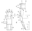
- the whole nozzle vane which shows 1st Embodiment is shown, (A) is a top view, (B) is a front view, (C) is a side view. (D) shows the shape of the nozzle vane leading edge bulge, and (E) shows the shape of the nozzle vane trailing edge bulge.
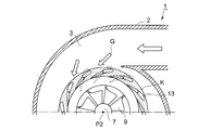
- the nozzle vane of 1st Embodiment is arrange
- the whole figure of the nozzle vane which shows a 2nd embodiment is shown, (A) is a top view, (B) is a front view, and (C) is a side view. It is principal part sectional drawing of the upper half which shows 3rd Embodiment.
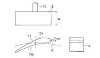
- FIG. 2 is a corresponding view of FIG. 1 showing an overall view of a prior art nozzle vane.
- (First embodiment) 7 and 8 are cross-sectional views of main parts of an example of a supercharger using the variable nozzle type radial turbine 1.
- a spiral scroll 3 is formed in a turbine casing 2 and a gas outlet passage 5 is formed on the inner peripheral side.
- a plurality of rotor blades 9 are fixed to the outer periphery of the turbine rotor 7 at equal intervals in the circumferential direction.
- the turbine rotor 7 is connected to a compressor (not shown) fixed coaxially by a rotor shaft 11, and the rotor shaft 11 is supported by a bearing casing with a bearing.
- a plurality of nozzle vanes 13 are provided inside the spiral scroll 3 in the circumferential direction to adjust the angle at which the gas flow G from the scroll 3 flows into the rotor blades 9 of the turbine rotor 7. 7 and 8, the nozzle vane 13 is a rotary type, and is rotatable about a support shaft 15 attached to the main body of the nozzle vane 13 shown in the figure.
- the nozzle vane 13 has a rectangular shape, and in the front view shown in FIG. 1B, it has an airfoil cross-sectional shape. Then, at the inlet front edge portion 17 of the nozzle vane 13 into which the working gas flows, the end portion on the shroud side 19 and the end portion on the hub side 21 which are both ends of the width W are more than the nozzle vane than the center portion W0 of the width W. 13 swelled to the pressure surface side 13a (the back side of the cross-sectional wing shape of FIG. 1B), and leading edge bulging portions 25, 25 are formed on both ends of the width W.
- the leading edge blade angle (the angle at which the leading edge is directed) ⁇ of the inlet leading edge 17 matches the gas inflow angle ⁇ (see FIG. 6) of the working gas flowing into the nozzle vane 13 over the entire width W. It has become.
- the end portion on the shroud side 19 and the end portion on the hub side 21 which are both ends of the width W are closer to the pressure surface side of the nozzle vane 13 than the central portion W0 of the width W.
- 13a (the back side of the cross-sectional wing shape of FIG. 1B) bulges, and trailing edge bulging portions 29 and 29 are formed on both end sides W1 and W2 of the width W, respectively.
- a leading edge bulging portion 25 is formed in a portion of L1 on the leading edge side with respect to the chord length L of the nozzle vane 13, and a trailing edge bulging portion 29 is formed in a portion of the trailing edge side L2.
- the gas inflow angle ⁇ 2 on the wall side is equal to the gas inflow angle ⁇ 1 at the center in the width direction (Z direction) of the passage and the gas inflow angle ⁇ 2 on the wall side, that is, the hub side and the shroud side. Is bigger.
- the leading edge blade angle ⁇ 1 of the central portion W0 of the width W of the nozzle vane 13 is set to coincide with ⁇ 1, and the leading edge blade angles ⁇ 2 of both end sides W1 and W2 of the width W coincide with ⁇ 2. It is set to be.
- leading edge blade angle ⁇ of the inlet leading edge portion 17 of the nozzle vane 13 coincides with the gas inflow angle ⁇ of the working gas flowing into the nozzle vane 13 in the entire width W, it flows into the nozzle vane from the turbine scroll.
- the collision loss of the working gas at the nozzle vane tip can be reduced.
- the end portions of the shroud side 19 and the hub side 21 are bulged so as to substantially coincide with the gas inflow angle ⁇ (see FIG. 6) of the working gas into the nozzle vane 13 in the entire width direction of the outlet rear edge portion 27. ing.
- the outflow flow at the rear end portion of the nozzle vane 13 is made uniform, that is, the circumferential inflow position of the working gas flowing out from the nozzle vane 13 into the rotor blade 9 is made uniform in the width direction of the flow path (with the central portion).
- the formation regions of the leading edge bulging portions 25 and 25 and the trailing edge bulging portions 29 and 29 are W1 and W2 on both sides in the width W direction, as shown in FIGS. are preferably formed in a range of about 15 to 20%. This corresponds to a region where a boundary layer is formed as shown in FIG. 6, and this region corresponds to the tendency that the gas inflow angle ⁇ increases due to the influence of the boundary layer.
- the bulge amounts ⁇ and ⁇ are set based on test results or simulation calculation results.
- the bulging amount ⁇ of the leading edge bulging portion 25 is the difference between the gas inflow angle ⁇ 1 at the center in the width direction (Z direction) of the passage and the gas inflow angle ⁇ 2 on the wall side, that is, the hub side and the shroud side. It is equivalent to.
- the bulging shape of the leading edge bulging portion 25 protrudes most at the positions of both end portions, and smoothly declines toward the central portion W0.
- (D) shows the shape of the nozzle vane leading edge bulging portion, and ⁇ 2 is a nozzle leading edge center line 25c connecting the leading edge point 25d of the leading edge bulging portion 25 and the rotation center P1 of the support shaft 15 of the nozzle vane 13. The angle formed by the tangent line 25b at the front edge point 25d of the arc passing through the front edge point 25d with the rotation center P2 of the rotor blade 9 as the center.
- (E) shows the shape of the nozzle vane trailing edge bulging portion
- ⁇ 2 is a nozzle trailing edge center line 29c connecting the trailing edge point 29d of the trailing edge bulging portion 29 and the rotation center P1 of the support shaft 15 of the nozzle vane 13.
- ⁇ 2 and ⁇ 2 have corresponding shapes so that a gap is not opened when the nozzle vane 13 is closed.
- the front edge bulging portion 25 and the rear edge bulging portion 29 between the adjacent nozzle vanes 13 and 13 have shapes corresponding to each other. Can be close when closed. Therefore, when the nozzle vane 13 is fully closed, the throat S formed between the adjacent nozzle vanes 13 and 13 can be made as narrow as possible, and the turbine performance can be improved.
- the operational effect of reducing the collision loss of the working gas flowing into the nozzle vane 13 from the turbine scroll 3 at the inlet front edge portion (tip portion) 17 of the nozzle vane 13, and the outlet of the nozzle vane 13 can be achieved.
- the front edge bulging portion 26 having the extension portion 31 is formed by extending the inlet front edge portion 17 of the nozzle vane 33 by L ′ in the length direction.
- the extended portion 31 has a shape in which the end surface portions of the shroud side 19 and the hub side 21 extend the most from the plan view of FIG. 3A and gradually decrease toward the center portion W0.
- W1 and W2 on both sides are preferably formed in a range of about 15 to 20%. Similar to the description of FIG. 1C, this corresponds to the region where the boundary layer shown in FIG. 6 is formed. In this region, the gas inflow angle ⁇ tends to increase due to the influence of the boundary layer. This is to make it correspond.
- a leading edge bulging portion 26 is formed at a portion L3 on the leading edge side with respect to the chord length La, and a trailing edge bulging portion 29 is formed at a portion on the trailing edge side L2.
- the nozzle length in the vicinity of both end portions in the width W direction is formed longer than the central portion W0, the length of the overlapping portion with the adjacent nozzle vanes 33, 33 is ensured, and the throat S Since the formation range is not shortened, a decrease in the flow velocity of the working gas flowing between the adjacent nozzle vanes 33 is prevented. That is, the blade angle ⁇ is raised at the leading edge bulging portion 26 and the blade angle ⁇ is also raised at the trailing edge bulging portion 29, so that the nozzle vane in which the throat S is formed in the overlapping portion between the adjacent nozzle vanes 33.
- the length of the overlapping portion can be ensured.
- the third embodiment further improves gas turbine efficiency by preventing gas leakage from the nozzle clearance as in the first and second embodiments.
- variable nozzle is provided with a clearance (nozzle clearance) 12 between the nozzle end and the wall surface in order to make the nozzle opening movable.
- the gas that passes through the nozzle clearance 12 (the gas that leaks without passing through the nozzle throat) is not converted into velocity energy, so the loss of the nozzle clearance 12 increases and turbine efficiency decreases.
- a gap formed between the end of the nozzle vane 13 and the side wall 37 is formed with a nozzle clearance 39 smaller than the nozzle clearance 12, and outside the annular range K is formed by the nozzle clearance 12 (FIG. 5). (See (B)).
- the annular range K is formed in a region where a throat is formed by adjacent nozzle vanes when the opening degree of the nozzle vane 13 is an intermediate opening degree to a small opening degree. That is, since the nozzle clearance loss ⁇ is proportional to the nozzle clearance area / throat area, the tendency of the loss increase due to the nozzle clearance 12 is a region where the gas expansion at the nozzle portion is larger than that of the rotor blade 9 of the turbine rotor 7. In addition, it becomes particularly remarkable in a region where the ratio of the throat area between the nozzles becomes small with respect to the nozzle clearance 12. Therefore, the nozzle clearance loss is effectively reduced by narrowing the nozzle clearance to the clearance 39 within the range of the middle opening to the small opening of the nozzle opening where the influence of the nozzle clearance on the turbine efficiency becomes large. Is obtained.
- the dimension adjusting structure of the nozzle clearance 12 of the third embodiment can be further improved by adding.
- the collision loss of the working gas flowing into the nozzle vane from the turbine scroll at the tip end of the nozzle vane is reduced and the outflow flow at the rear end of the nozzle vane is made uniform to reduce the secondary flow loss at the nozzle vane and the moving blade.
- the turbine clearance can be improved and the effect of the nozzle clearance on the turbine efficiency can be increased.
- the turbine efficiency can be further improved, so that it is suitable for use in a radial turbine such as a supercharger (exhaust turbocharger), a small gas turbine, and an expansion turbine.
Landscapes
- Engineering & Computer Science (AREA)
- Mechanical Engineering (AREA)
- General Engineering & Computer Science (AREA)
- Chemical & Material Sciences (AREA)
- Combustion & Propulsion (AREA)
- Physics & Mathematics (AREA)
- Fluid Mechanics (AREA)
- Turbine Rotor Nozzle Sealing (AREA)
- Supercharger (AREA)
- Control Of Turbines (AREA)
Abstract
タービンスクロールからノズルベーンへ流入する作動ガスのノズルベーン先端部における衝突損失の低減およびノズルベーンの後端部における流出流れの均一化を行って、動翼における衝突損失、2次流れ損失を抑制してタービン効率を向上させることを目的とし、渦巻状のスクロール3の内側に周方向に複数個配置され、スクロール3から動翼9への作動ガスの流れを調整するノズルベーン13を備えたラジアルタービン1において、ノズルベーン13の入口前縁部17の幅方向の両端部近傍を、中央部よりもノズルベーンの圧力面側に膨出して前縁膨出部25を形成し、ノズルベーン13に流入する作動ガスのガス流入角度と一致するようにし、さらに、ノズルベーン13の出口後縁部27の幅方向の両端部近傍を、中央部よりも圧力面側に膨出させた後縁膨出部29を形成することを特徴とする。
Description
本発明は、ラジアルタービンに関し、特に、渦巻状のスクロールの内側に周方向に複数個配置され、スクロールからタービンロータの動翼への作動ガスの流れを調整するノズルベーンの構造に関する。
自動車用内燃機関等に用いられる比較的小型の過給機(排気ターボチャージャ)には、作動ガスをタービンケーシング内に形成された渦巻状のスクロールから該スクロールの内側に位置するタービンロータの動翼へと半径方向に流入させて該動翼に作用させた後軸方向に流出させることにより該タービンロータを回転駆動するように構成されたラジアルタービンが多く採用されている。
そして、動翼へ流入する作動ガスの流れを改善してラジアルタービンの効率を向上するものとして、動翼の外周側にノズルベーンを周上に複数個配置し、その角度を可変化したもの、または固定化したものが採用されている。
そして、動翼へ流入する作動ガスの流れを改善してラジアルタービンの効率を向上するものとして、動翼の外周側にノズルベーンを周上に複数個配置し、その角度を可変化したもの、または固定化したものが採用されている。
図7,図8に、可変ノズル式のラジアルタービンを用いた過給機の一例の要部断面図を示す。図においてタービンケーシング2内には、渦巻状のスクロール3、内周側にガス出口通路5(図7には不図示)が形成されている。
また、タービンロータ7の外周に複数の動翼9が円周方向等間隔に固着されて構成されている。また、タービンロータ7はローターシャフト11によって同軸に固定された図示しないコンプレッサと接続されており、このローターシャフト11は軸受ケーシングに軸受で支持されている。
また、タービンロータ7の外周に複数の動翼9が円周方向等間隔に固着されて構成されている。また、タービンロータ7はローターシャフト11によって同軸に固定された図示しないコンプレッサと接続されており、このローターシャフト11は軸受ケーシングに軸受で支持されている。
また、渦巻状のスクロール3の内側に周方向に複数個配置されてスクロール3からのガス流Gを調整してタービンロータ7の動翼9へ流すノズルベーン13が設けられている。
この図7、8においては、ノズルベーン13は可変式のものを示し、図に示すノズルベーン13の本体に取り付けられた支持軸15を回転軸として回転可能にした可変式である。
この図7、8においては、ノズルベーン13は可変式のものを示し、図に示すノズルベーン13の本体に取り付けられた支持軸15を回転軸として回転可能にした可変式である。
ラジアルタービンのノズルベーンに関する先行技術としては、特許文献1(特開2005-351241号公報)、特許文献2(特表2011-509371号公報)、特許文献3(特開2000-18004号公報)が挙げられる。
特許文献1には、可変式のノズル用ベーンが示され、車両用ターボ過給機等の排気タービンの低負荷運転領域を含む使用負荷範囲の全域にわたって良好なノズル特性を得るために、ベーンの背面の下流端部の翼長の少なくとも一部に亘って翼型断面形状より山形に膨出した流体そらせ隆起を設けることが示されている。
特許文献1には、可変式のノズル用ベーンが示され、車両用ターボ過給機等の排気タービンの低負荷運転領域を含む使用負荷範囲の全域にわたって良好なノズル特性を得るために、ベーンの背面の下流端部の翼長の少なくとも一部に亘って翼型断面形状より山形に膨出した流体そらせ隆起を設けることが示されている。
また、特許文献2には、可変式のターボチャージャ用のガイドベーンが示され、当該ガイドベーンの外形形状の曲率線が、不連続的な延びを有する少なくとも1つ又は複数の領域を有して形成され、所望の使用目的に応じた多数の流動パターンを実現することが示されている。
また、特許文献3には、ノズル付きラジアルタービンにおいて、可変ノズルのハブ側及びシュラウド側の両壁近傍でノズル流入角が大きくなることにより生じるノズル損失を抑えるために、ノズル前縁部のハブ側壁面近傍とシュラウド側壁面近傍の翼角を流路中央の翼角より大きい形状としたことが開示されている。
前述の図7、8に示したラジアルタービンにおいては、作動ガスはスクロール3の渦巻きに沿って周回しながら周方向に複数個配置されたノズルベーン13の間に流入する。このノズルベーン13へのガス流入速度は、ノズルベーン13の幅(高さ)方向(図6のZ方向)において、異なる速度分布を持つ。
すなわち、ノズルベーン13の入口部のガス流入速度Cは、図6に示すように、入口前縁部17の幅Wの両側において全幅の15~20%に形成される3次元境界層によって、ガス速度Cの周方向成分である周方向速度Cθは前記入口前縁部17の中央部が大きく両端の角部つまりシュラウド側19及びハブ側21が小さくなる。また半径方向成分である半径方向速度CRは図6に示すように、入口前縁部17の中央部が小さく両端の角部つまりシュラウド側19及びハブ側21が大きくなるような分布となる。
すなわち、ノズルベーン13の入口部のガス流入速度Cは、図6に示すように、入口前縁部17の幅Wの両側において全幅の15~20%に形成される3次元境界層によって、ガス速度Cの周方向成分である周方向速度Cθは前記入口前縁部17の中央部が大きく両端の角部つまりシュラウド側19及びハブ側21が小さくなる。また半径方向成分である半径方向速度CRは図6に示すように、入口前縁部17の中央部が小さく両端の角部つまりシュラウド側19及びハブ側21が大きくなるような分布となる。
そして、前記ノズルベーン13の入口の幅Wの方向に、流入ガスの流動分布つまり流動歪みがあると該ノズルベーン13での流動損失が増加してタービン効率の低下を招く。
すなわち、前記ノズルベーン13への最適なガス流入角度β1に合わせたノズルベーン13の入口中央部に対して入口前縁部17の壁側つまりハブ側21及びシュラウド側19のガス流入角度β2が大きくなり、ハブ側21及びシュラウド側19においてガス流入角度βの差つまり衝突角度(インシデンス角度、インシデンス角度はノズル前縁の翼角度とガス流入角度との差)が大きくなると、ガスが前記ノズルベーン13の先端部において負圧面側13b(図9参照、13aを圧力面側とする)に衝突角度(インシデンス角度)を持って流入することとなってノズルベーン13の入口前縁部17の衝突損失を生じ、ノズルベーン13から動翼9へ向かう流れに2次流れ損失が増加し、タービン効率が低下する問題があった。
すなわち、前記ノズルベーン13への最適なガス流入角度β1に合わせたノズルベーン13の入口中央部に対して入口前縁部17の壁側つまりハブ側21及びシュラウド側19のガス流入角度β2が大きくなり、ハブ側21及びシュラウド側19においてガス流入角度βの差つまり衝突角度(インシデンス角度、インシデンス角度はノズル前縁の翼角度とガス流入角度との差)が大きくなると、ガスが前記ノズルベーン13の先端部において負圧面側13b(図9参照、13aを圧力面側とする)に衝突角度(インシデンス角度)を持って流入することとなってノズルベーン13の入口前縁部17の衝突損失を生じ、ノズルベーン13から動翼9へ向かう流れに2次流れ損失が増加し、タービン効率が低下する問題があった。
一方、特許文献1に示される技術は、前述のようにベーンの背面の下流端部の翼長の少なくとも一部に亘って翼型断面形状より膨出した流体そらせ隆起を設けて、ベーンの下流端を出たところで流れが該ベーンの腹側へ回り込む流れを防止するものであり、ベーンの下流端部から流出してタービンロータの動翼に流入する流れ角の均一化までは開示されていない。
また、特許文献2においても、スクロールからの作動ガスが流入されるベーン先端部、さらに後端部における作動ガスの流れ角度の均一化については示されていない。
また、特許文献3においても、ベーン先端部におけるインシデンス角度(衝突角度)の均一化については示されているものの、ベーンの下流端部から流出してタービンロータの動翼に流入する流れ角の均一化までは開示されていない。
また、特許文献2においても、スクロールからの作動ガスが流入されるベーン先端部、さらに後端部における作動ガスの流れ角度の均一化については示されていない。
また、特許文献3においても、ベーン先端部におけるインシデンス角度(衝突角度)の均一化については示されているものの、ベーンの下流端部から流出してタービンロータの動翼に流入する流れ角の均一化までは開示されていない。
そこで、本発明はこのような課題に鑑みてなされたものであり、タービンスクロールからノズルベーンへ流入する作動ガスのノズルベーン先端部における衝突損失の低減、およびノズルベーンの後端部における流出流れの均一化を行って、ノズルベーンおよび動翼における2次流れ損失を抑制してタービン効率を向上させることを目的とする。
本発明はかかる目的を達成するもので、渦巻状のスクロールの内側に周方向に複数個配置され、スクロールからタービンロータの動翼への作動ガスの流れを調整するノズルベーンを備えたラジアルタービンにおいて、前記ノズルベーンの入口前縁部の幅方向の両端部近傍を、幅方向の中央部よりも該ノズルベーンの圧力面側に膨出して前縁膨出部を形成し、入口前縁部の前縁翼角度を幅方向全域において前記ノズルベーンに流入する作動ガスのガス流入角度と一致するようにし、さらに、前記ノズルベーンの後縁部の幅方向の両端部近傍を、中央部よりも該ノズルベーンの圧力面側に膨出させた後縁膨出部を形成したことを特徴とする。
かかる発明によれば、タービンスクロールからノズルベーンへ流入する作動ガスのノズルベーン先端部における衝突損失の低減が図れるとともに、ノズルベーンの後端部における流出流れの均一化がなされることによって、ノズルから動翼へ流入する作動ガスの流れの均一化によって、動翼による作動損失の低減が図れて、タービン全体のタービン効率を向上できる。
また、本発明において、好ましくは、前記幅方向の両端部近傍におけるノズルベーンの全長を前記幅方向の中央部における全長より長く形成するとよい。
このような構成を採用することによって、前縁膨出部が形成される幅方向の両端部分が延長して設けられて全長が長くなるため、隣接するそれぞれのノズルベーンの重なりによって形成されるスロートが形成される距離が確保され、その結果、スロートによる作動ガスの調整を十分行うことができる。すなわち、前縁膨出部においては翼角が立ち上がるため隣接するノズルベーン間の重なり距離が小さくなる傾向にあるが、本発明ではこのような隣接のノズルベーン間の重なり部の長さを確保できるようになる。
このような構成を採用することによって、前縁膨出部が形成される幅方向の両端部分が延長して設けられて全長が長くなるため、隣接するそれぞれのノズルベーンの重なりによって形成されるスロートが形成される距離が確保され、その結果、スロートによる作動ガスの調整を十分行うことができる。すなわち、前縁膨出部においては翼角が立ち上がるため隣接するノズルベーン間の重なり距離が小さくなる傾向にあるが、本発明ではこのような隣接のノズルベーン間の重なり部の長さを確保できるようになる。
また、本発明において、好ましくは、前記ノズルベーンがノズル長さの中間部を回転中心として回動可能に支持される可変式のノズルベーンからなり、隣設するノズルベーンの一方のノズルベーンの前記前縁膨出部と他方のノズルベーンの前記後縁膨出部とが前記ノズルベーンを全閉状態の時に近接するように形成されるとよい。
このような構成を採用することによって、ノズルベーンの全閉時おいて、スロートを極力狭く設定することができ、タービン性能を低下させることがない。
このような構成を採用することによって、ノズルベーンの全閉時おいて、スロートを極力狭く設定することができ、タービン性能を低下させることがない。
また、本発明において、好ましくは、前記ノズルベーンがノズル長さの中間部を回転中心として回動可能に支持される可変式のノズルベーンからなり、各ノズルベーンの回動軸近傍を連ねて形成される環状範囲内においてのみ、前記ノズルベーンの幅方向の両端部と側壁との隙間が、前記環状範囲外における前記両端部と前記側壁との隙間より狭く形成されているとよい。
可変式のノズルは、ノズル開度を可動とするため、ノズル端部と壁面の間に、クリアランス(隙間)が設けられている。このクリアランスを通過するガス(ノズルのスロートを通過せずに漏れるガス)は、速度エネルギーに変換されないため、ノズルクリアランスの損失が増大し、タービン効率が低下する。
従って、本発明では前記のような構成を採用することで、ノズルクリアランスの損失を防止することで、前記したノズルベーン先端部における衝突損失の低減およびノズルベーンの後端部における流出流れの均一化によるタービン効率を向上と合わされて、さらに効率向上が図れる。
また、本発明において、好ましくは、前記環状範囲はノズルベーンの開度が中間開度~小開度の範囲内において隣接するノズルベーンによってスロートが形成される領域であるとよい。
すなわち、ノズルクリアランスによる損失増大の傾向は、タービンロータの動翼に比べノズル部でのガス膨張が大きい領域であり、かつノズルクリアランスに対して、ノズル間のスロート面積の割合が小さくなる領域で、特に顕著になるため、タービン効率へのノズルの影響が大きくなるノズル開度の中開度~小開度の範囲内において隣接するノズルベーンによってスロートが形成される領域であるとノズルクリアランスの損失防止が効果的に得られる。
また、本発明において好ましくは、前記ノズルベーンの入口前縁部において、幅方向の両端部近傍を、幅方向の中央部よりノズルベーンの圧力面側に約2度~13度の範囲で翼角度を立たせる方向に膨出するとよく、また、前記ノズルベーンの出口後縁部において、幅方向の両端部近傍を、幅方向の中央部よりノズルベーンの圧力面側に約2度~8度の範囲で翼角度を立たせる方向に膨出するとよい。
本発明によれば、タービンスクロールからノズルベーンへ流入する作動ガスのノズルベーン先端部における衝突損失の低減およびノズルベーンの後端部における流出流れの均一化を行ってタービン動翼における衝突損失及び2次流れ損失を抑制してタービン効率を向上させることができる。
また、タービン効率へのノズルクリアランスの影響が大きくなるノズル開度の中開度~小開度の範囲内において、ノズルクリアランスの寸法を小さくして損失防止を行うことで、タービン効率をさらに向上させることができる。
また、タービン効率へのノズルクリアランスの影響が大きくなるノズル開度の中開度~小開度の範囲内において、ノズルクリアランスの寸法を小さくして損失防止を行うことで、タービン効率をさらに向上させることができる。
以下、本発明を図に示した実施形態を用いて詳細に説明する。
但し、この実施形態に記載されている構成部品の寸法、材質、形状、その相対配置などは特に特定的な記載がない限り、この発明の範囲をそれのみに限定する趣旨ではなく、単なる説明例にすぎない。
但し、この実施形態に記載されている構成部品の寸法、材質、形状、その相対配置などは特に特定的な記載がない限り、この発明の範囲をそれのみに限定する趣旨ではなく、単なる説明例にすぎない。
(第1実施形態)
図7、8に、可変ノズル式のラジアルタービン1を用いた過給機の一例の要部断面図を示す。図においてタービンケーシング2内には、渦巻状のスクロール3、内周側にガス出口通路5が形成されている。
また、タービンロータ7の外周に複数の動翼9が円周方向等間隔に固着されて構成されている。また、タービンロータ7はローターシャフト11によって同軸に固定された図示しないコンプレッサと接続されており、このローターシャフト11は軸受ケーシングに軸受で支持されている。
図7、8に、可変ノズル式のラジアルタービン1を用いた過給機の一例の要部断面図を示す。図においてタービンケーシング2内には、渦巻状のスクロール3、内周側にガス出口通路5が形成されている。
また、タービンロータ7の外周に複数の動翼9が円周方向等間隔に固着されて構成されている。また、タービンロータ7はローターシャフト11によって同軸に固定された図示しないコンプレッサと接続されており、このローターシャフト11は軸受ケーシングに軸受で支持されている。
また、渦巻状のスクロール3の内側に周方向に複数個配置されて、スクロール3からのガス流Gをタービンロータ7の動翼9へ流入する角度を調整するノズルベーン13が設けられている。
この図7、8においては、ノズルベーン13は回転式のものを示し、図に示すノズルベーン13の本体に取り付けられた支持軸15を回転軸として回転可能になっている。
この図7、8においては、ノズルベーン13は回転式のものを示し、図に示すノズルベーン13の本体に取り付けられた支持軸15を回転軸として回転可能になっている。
ノズルベーン13は、その本体部分は図1(A)の平面図に示すように、長方形状をしており、(B)に示す正面図においては翼形の断面形状を有している。そして、作動ガスが流入するノズルベーン13の入口前縁部17において、幅Wの両端部であるシュラウド側19の端部とハブ側21の端部の部分が、幅Wの中央部W0よりもノズルベーン13の圧力面側13a(図1(B)の断面翼形状の背側)に膨出して、幅Wの両端側に前縁膨出部25、25を形成している。
そして、入口前縁部17の前縁翼角度(前縁部の指向する角度)αが、幅Wの全域においてノズルベーン13に流入する作動ガスのガス流入角度β(図6参照)と一致するようなっている。
そして、入口前縁部17の前縁翼角度(前縁部の指向する角度)αが、幅Wの全域においてノズルベーン13に流入する作動ガスのガス流入角度β(図6参照)と一致するようなっている。
さらに、ノズルベーンの出口後縁部27においても、幅Wの両端部であるシュラウド側19の端部とハブ側21の端部の部分が、幅Wの中央部W0よりもノズルベーン13の圧力面側13a(図1(B)の断面翼形状の背側)に膨出して、幅Wの両端側W1、W2に後縁膨出部29、29を形成している。
ノズルベーン13の翼弦長Lに対して前縁側のL1の部分に前縁膨出部25が形成され、後縁側L2の部分に後縁膨出部29が形成されている。
ノズルベーン13の翼弦長Lに対して前縁側のL1の部分に前縁膨出部25が形成され、後縁側L2の部分に後縁膨出部29が形成されている。
このようにノズルベーン13の入口前縁部17の幅方向の全域、および出口後縁部27の幅方向全域において、作動ガスのノズルベーン13へのガス流入角度β(図6参照)と一致するようにシュラウド側19およびハブ側21の端部を膨出させている。
具体的には、図6において、通路の幅方向(Z方向)の中央部のガス流入角度β1と、壁側つまりハブ側及びシュラウド側のガス流入角度β2とでは、壁側のガス流入角度β2の方が大きくなる。これに対応するように、ノズルベーン13の幅Wの中央部W0の前縁翼角度α1がβ1に一致するように設定され、幅Wの両端側W1、W2の前縁翼角度α2がβ2に一致するように設定されている。
従って、ノズルベーン13の入口前縁部17の前縁翼角度αが、幅Wの全域においてノズルベーン13に流入する作動ガスのガス流入角度βと一致するようなっているため、 タービンスクロールからノズルベーンへ流入する作動ガスのノズルベーン先端部における衝突損失を低減できる。
従って、ノズルベーン13の入口前縁部17の前縁翼角度αが、幅Wの全域においてノズルベーン13に流入する作動ガスのガス流入角度βと一致するようなっているため、 タービンスクロールからノズルベーンへ流入する作動ガスのノズルベーン先端部における衝突損失を低減できる。
また、出口後縁部27の幅方向全域においても、作動ガスのノズルベーン13へのガス流入角度β(図6参照)と略一致させるようにシュラウド側19およびハブ側21の端部を膨出させている。このため、ノズルベーン13の後端部における流出流れの均一化によって、すなわち、ノズルベーン13から流出した作動ガスの動翼9への周方向流入位置が流路の幅方向で均一化する(中央部とシュラウド側およびハブ側との動翼9への周方向流入位置のずれを近づけるようにする)ことによって、動翼9による作動損失の低減が図れて、タービン全体のタービン効率を向上できる。
なお、前縁膨出部25、25、及び、後縁膨出部29、29の形成領域は、図1(A)~(C)に示すように、幅W方向において、両側のW1、W2をそれぞれ15~20%程度の範囲に形成するとよい。これは図6に示すように境界層が形成される領域に相当させたものであり、この領域では境界層による影響でガス流入角度βが大きくなる傾向に対応させてある。
また、ノズルベーン13の前縁膨出部25の膨出量Δαについては、幅方向の両端部近傍を、幅方向の中央部よりノズルベーンの圧力面側にΔα=約2度~13度の範囲で翼角度を立たせる方向に膨出するとよく、また、ノズルベーン13の後縁膨出部29の膨出量Δβについては、幅方向の両端部近傍を、幅方向の中央部よりノズルベーンの圧力面側にΔβ=約2度~8度の範囲で翼角度を立たせる方向に膨出するとよい(図1(B)参照)。この膨出量Δα、Δβについては、試験結果またはシミュレーション算出結果を基に設定している。
なお、この前縁膨出部25の膨出量Δαは、通路の幅方向(Z方向)の中央部のガス流入角度β1と、壁側つまりハブ側及びシュラウド側のガス流入角度β2との差に相当するものである。
なお、この前縁膨出部25の膨出量Δαは、通路の幅方向(Z方向)の中央部のガス流入角度β1と、壁側つまりハブ側及びシュラウド側のガス流入角度β2との差に相当するものである。
また、前縁膨出部25の膨出形状は、図1(C)に示すように、両端部の位置で最も突出しており、中央部W0に向かうように滑らかに低下している。
(D)はノズルベーン前縁膨出部の形状を示し、α2は、前縁膨出部25の前縁点25dとノズルベーン13の支持軸15の回転中心P1とを結ぶノズル前縁中心線25cと、動翼9の回転中心P2を中心として前縁点25dを通る円弧の前縁点25dにおける接線25bとのなす角度である。
(E)はノズルベーン後縁膨出部の形状を示し、γ2は、後縁膨出部29の後縁点29dとノズルベーン13の支持軸15の回転中心P1とを結ぶノズル後縁中心線29cと、動翼9の回転中心P2を中心として後縁点29dを通る円弧の後縁点29dにおける接線29bとのなす角度である。
また、前記α2及びγ2はノズルベーン13を閉じたときに隙間が開かないように対応する形状にもなっている。
(D)はノズルベーン前縁膨出部の形状を示し、α2は、前縁膨出部25の前縁点25dとノズルベーン13の支持軸15の回転中心P1とを結ぶノズル前縁中心線25cと、動翼9の回転中心P2を中心として前縁点25dを通る円弧の前縁点25dにおける接線25bとのなす角度である。
(E)はノズルベーン後縁膨出部の形状を示し、γ2は、後縁膨出部29の後縁点29dとノズルベーン13の支持軸15の回転中心P1とを結ぶノズル後縁中心線29cと、動翼9の回転中心P2を中心として後縁点29dを通る円弧の後縁点29dにおける接線29bとのなす角度である。
また、前記α2及びγ2はノズルベーン13を閉じたときに隙間が開かないように対応する形状にもなっている。
従って、図2に示すように、隣接して設けられるノズルベーン13、13間の前縁膨出部25と後縁膨出部29とが、互いに対応する形状からなっているため、ノズルベーン13の全閉時において、近接することができる。従って、ノズルベーン13の全閉時おいて、隣接するノズルベーン13、13間に形成されるスロートSを極力狭くすることができ、タービン性能を向上できる。
以上の第1実施形態によれば、タービンスクロール3からノズルベーン13へ流入する作動ガスのノズルベーン13の入口前縁部(先端部)17における衝突損失の低減が図れるという作用効果と、ノズルベーン13の出口後縁部(後端部)27における流出流れの均一化がなされることによって、ノズルベーン13から動翼9へ流入する作動ガスの均一化が得られるという作用効果とが重なりあって、ノズルベーン13による作動ガス流の流れの損失低減と、動翼9による作動損失の低減が図れて、タービン全体のタービン効率を向上できる。
(第2実施形態)
次に、図3を参照して、第2実施形態について説明する。この第2実施形態は、入口前縁部17の部分を翼の長さ方向に延ばしたものである。その他の構成は第1実施形態と同様である。
次に、図3を参照して、第2実施形態について説明する。この第2実施形態は、入口前縁部17の部分を翼の長さ方向に延ばしたものである。その他の構成は第1実施形態と同様である。
図3のように、ノズルベーン33の入口前縁部17の部分を長さ方向にL'だけ延ばして延長部31を有した前縁膨出部26を形成している。
この延長部31は、図3(A)の平面図より、シュラウド側19およびハブ側21の端面部を最も伸ばし、そこから徐々に中央部W0に向かって低下していく形状をしている。幅W方向において、両側のW1、W2は、それぞれ15~20%程度の範囲において形成するとよい。これは図1(C)の説明と同様に、図6に示す境界層が形成される領域に相当させたものであり、この領域にでは境界層による影響でガス流入角度βが大きくなる傾向に対応させるためである。
また、翼弦長Laに対して前縁側のL3の部分に前縁膨出部26が形成され、後縁側L2の部分に後縁膨出部29が形成されている。
この延長部31は、図3(A)の平面図より、シュラウド側19およびハブ側21の端面部を最も伸ばし、そこから徐々に中央部W0に向かって低下していく形状をしている。幅W方向において、両側のW1、W2は、それぞれ15~20%程度の範囲において形成するとよい。これは図1(C)の説明と同様に、図6に示す境界層が形成される領域に相当させたものであり、この領域にでは境界層による影響でガス流入角度βが大きくなる傾向に対応させるためである。
また、翼弦長Laに対して前縁側のL3の部分に前縁膨出部26が形成され、後縁側L2の部分に後縁膨出部29が形成されている。
第2実施形態によれば、幅W方向の両端部近傍のノズル長さを中央部W0より長く形成するため、隣接するノズルベーン33、33との重なり部分の長さが確保されて、スロートSの形成範囲を短くすることがないため、隣接するノズルベーン33間を流れる作動ガスの流速の低下が防止される。
すなわち、前縁膨出部26においては翼角αを立ち上げ、さらに後縁膨出部29においても翼角γが立ち上がるため、隣接するノズルベーン33間の重なりの部分においてスロートSが形成されるノズルベーンの長さ方向の距離を確保できない問題が生じるおそれがあるが、本実施形態ではこのような重なり部の長さを確保できる。
すなわち、前縁膨出部26においては翼角αを立ち上げ、さらに後縁膨出部29においても翼角γが立ち上がるため、隣接するノズルベーン33間の重なりの部分においてスロートSが形成されるノズルベーンの長さ方向の距離を確保できない問題が生じるおそれがあるが、本実施形態ではこのような重なり部の長さを確保できる。
なお、第2実施形態としては前縁膨出部26の部分だけを延長した例を説明したが、後縁膨出部29の部分も延長するようにしてもよく、このように前縁側と後縁側を共に延長することで、隣接するノズルベーンの重なり部分の長さが一層確保されるので、スロート部分の長さが確保されて作動ガスの調整低下が防止される。
(第3実施形態)
次に図4、5を参照して、第3実施形態について説明する。
この第3実施形態は、第1、2実施形態にさらにノズルクリアランスからのガス漏れを防止してタービン効率を向上させるものである。
次に図4、5を参照して、第3実施形態について説明する。
この第3実施形態は、第1、2実施形態にさらにノズルクリアランスからのガス漏れを防止してタービン効率を向上させるものである。
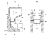
図5に示すように、可変式ノズルは、ノズル開度を可動とするため、ノズル端部と壁面の間に、クリアランス(ノズルクリアランス)12が設けられている。このノズルクリアランス12を通過するガス(ノズルのスロートを通過せずに漏れるガス)は、速度エネルギーに変換されないため、ノズルクリアランス12の損失が増大し、タービン効率が低下する。
従って、第3実施形態では、図4、5に示すように、ノズルベーン13がノズル長さの中間部を回転中心として回動可能に支持する支持軸15の近傍を連ねて形成される環状範囲K内においては、ノズルベーン13の端部と側壁37との間に形成される隙間がノズルクリアランス12より小さいノズルクリアランス39が形成され、環状範囲K外においてはノズルクリアランス12によって形成されている(図5(B)参照)。
そして、環状範囲Kはノズルベーン13の開度が中間開度~小開度のときに隣接するノズルベーンによってスロートが形成される領域に形成される。すなわち、ノズルクリアランス損失Δηは、ノズルクリアランス面積/スロート面積に比例するため、ノズルクリアランス12による損失増大の傾向は、タービンロータ7の動翼9に比べノズル部でのガス膨張が大きい領域であり、かつノズルクリアランス12に対して、ノズル間のスロート面積の割合が小さくなる領域において特に顕著になる。
このため、タービン効率へのノズルクリアランスの影響が大きくなるノズル開度の中開度~小開度の範囲内において、ノズルクリアランスを狭めて隙間39とすることによって、ノズルクリアランス損失の低減を効果的に得られる。
このため、タービン効率へのノズルクリアランスの影響が大きくなるノズル開度の中開度~小開度の範囲内において、ノズルクリアランスを狭めて隙間39とすることによって、ノズルクリアランス損失の低減を効果的に得られる。
従って、前記第1実施形態、および第2実施形態のノズルベーン13の前縁膨出部25、26および後縁膨出部29の形成に加えて、第3実施形態のノズルクリアランス12の寸法調整構造を付加することによって、タービン効率をさらに向上させることができる。
本発明によれば、タービンスクロールからノズルベーンへ流入する作動ガスのノズルベーン先端部における衝突損失の低減およびノズルベーンの後端部における流出流れの均一化を行ってノズルベーンおよび動翼での2次流れ損失を抑制して、タービン効率を向上させることができ、さらにタービン効率へのノズルクリアランスの影響が大きくなるノズル開度の中開度~小開度の範囲内において、ノズルクリアランスの寸法を小さくして損失防止を行うことで、タービン効率をさらに向上させることができるので、過給機(排気ターボチャージャ)、小型ガスタービン、膨脹タービン等のラジアルタービンへ用いることに適している。
1 ラジアルタービン
2 タービンケーシング
3 スクロール
7 タービンロータ
9 動翼
12、39 ノズルクリアランス
13 ノズルベーン
17 入口前縁部
25、26 前縁膨出部
27 出口後縁部
29 後縁膨出部
31 延長部
α 前縁翼角度
β ガス流入角度
γ 後縁翼角度
W 幅
W0 幅の中央部
K 環状範囲
L、La 翼弦長
S スロート
2 タービンケーシング
3 スクロール
7 タービンロータ
9 動翼
12、39 ノズルクリアランス
13 ノズルベーン
17 入口前縁部
25、26 前縁膨出部
27 出口後縁部
29 後縁膨出部
31 延長部
α 前縁翼角度
β ガス流入角度
γ 後縁翼角度
W 幅
W0 幅の中央部
K 環状範囲
L、La 翼弦長
S スロート
Claims (7)
- 渦巻状のスクロールの内側に周方向に複数個配置され、スクロールからタービンロータの動翼への作動ガスの流れを調整するノズルベーンを備えたラジアルタービンにおいて、
前記ノズルベーンの入口前縁部の幅方向の両端部近傍を、幅方向の中央部よりも該ノズルベーンの圧力面側に膨出して前縁膨出部を形成し、入口前縁部の前縁翼角度を幅方向全域において前記ノズルベーンに流入する作動ガスのガス流入角度と一致するようにし、さらに、前記ノズルベーンの後縁部の幅方向の両端部近傍を、中央部よりも該ノズルベーンの圧力面側に膨出させた後縁膨出部を形成したことを特徴とするラジアルタービン。 - 前記幅方向の両端部近傍におけるノズルベーンの全長を前記幅方向の中央部における全長より長く形成したことを特徴とする請求項1記載のラジアルタービン。
- 前記ノズルベーンがノズル長さの中間部を回転中心として回動可能に支持される可変式のノズルベーンからなり、隣設するノズルベーンの一方のノズルベーンの前記前縁膨出部と他方のノズルベーンの前記後縁膨出部とが前記ノズルベーンを全閉状態の時に近接するように形成されたことを特徴とする請求項1または2記載のラジアルタービン。
- 前記ノズルベーンがノズル長さの中間部を回転中心として回動可能に支持される可変式のノズルベーンからなり、各ノズルベーンの回動軸近傍を連ねて形成される環状範囲内においてのみ、前記ノズルベーンの幅方向の両端部と側壁との隙間が、前記環状範囲外における前記両端部と前記側壁との隙間より狭く形成されていることを特徴とする請求項1ないし3のいずれか一項に記載のラジアルタービン。
- 前記環状範囲はノズルベーンの開度が中間開度~小開度の範囲内において隣接するノズルベーンによってスロートが形成される領域であることを特徴とする請求項4記載のラジアルタービン。
- 前記ノズルベーンの入口前縁部において、幅方向の両端部近傍を、幅方向の中央部よりノズルベーンの圧力面側に2度~13度の範囲で翼角度を立たせる方向に膨出したことを特徴とする請求項1記載のラジアルタービン。
- 前記ノズルベーンの出口後縁部において、幅方向の両端部近傍を、幅方向の中央部よりノズルベーンの圧力面側に2度~8度の範囲で翼角度を立たせる方向に膨出したことを特徴とする請求項1記載のラジアルタービン。
Applications Claiming Priority (3)
| Application Number | Priority Date | Filing Date | Title |
|---|---|---|---|
| JP2011261737 | 2011-11-30 | ||
| JP2012256911A JP6000089B2 (ja) | 2011-11-30 | 2012-11-22 | ラジアルタービン |
| JP2012-256911 | 2012-11-22 |
Publications (1)
| Publication Number | Publication Date |
|---|---|
| WO2014080889A1 true WO2014080889A1 (ja) | 2014-05-30 |
Family
ID=48535261
Family Applications (2)
| Application Number | Title | Priority Date | Filing Date |
|---|---|---|---|
| PCT/JP2012/079504 Ceased WO2013080795A1 (ja) | 2011-11-30 | 2012-11-14 | ラジアルタービン |
| PCT/JP2013/081123 Ceased WO2014080889A1 (ja) | 2011-11-30 | 2013-11-19 | ラジアルタービン |
Family Applications Before (1)
| Application Number | Title | Priority Date | Filing Date |
|---|---|---|---|
| PCT/JP2012/079504 Ceased WO2013080795A1 (ja) | 2011-11-30 | 2012-11-14 | ラジアルタービン |
Country Status (5)
| Country | Link |
|---|---|
| US (1) | US10072513B2 (ja) |
| EP (1) | EP2787181B1 (ja) |
| JP (1) | JP6000089B2 (ja) |
| CN (1) | CN103946487B (ja) |
| WO (2) | WO2013080795A1 (ja) |
Cited By (2)
| Publication number | Priority date | Publication date | Assignee | Title |
|---|---|---|---|---|
| JP2023118180A (ja) * | 2022-02-15 | 2023-08-25 | 三菱重工マリンマシナリ株式会社 | タービン及び過給機 |
| WO2025022557A1 (ja) * | 2023-07-25 | 2025-01-30 | 三菱重工マリンマシナリ株式会社 | タービン及び過給機 |
Families Citing this family (27)
| Publication number | Priority date | Publication date | Assignee | Title |
|---|---|---|---|---|
| DE102011108195B4 (de) * | 2011-07-20 | 2022-10-27 | Ihi Charging Systems International Gmbh | Turbine für einen Abgasturbolader |
| JP6225515B2 (ja) * | 2013-07-05 | 2017-11-08 | 株式会社Ihi | 可変ノズルユニット及び可変容量型過給機 |
| DE102013224572A1 (de) | 2013-11-29 | 2015-06-03 | Bosch Mahle Turbo Systems Gmbh & Co. Kg | Abgasturbolader, insbesondere für ein Kraftfahrzeug |
| DE102013225642B4 (de) * | 2013-12-11 | 2020-09-17 | Vitesco Technologies GmbH | Abgasturbolader mit einem verstellbaren Leitgitter |
| JP6326912B2 (ja) * | 2014-03-31 | 2018-05-23 | 株式会社Ihi | 可変ノズルユニット及び可変容量型過給機 |
| EP3163030B1 (en) | 2014-08-27 | 2020-10-07 | Mitsubishi Heavy Industries Engine & Turbocharger, Ltd. | On-off valve device and rotary machine |
| DE102015212808A1 (de) * | 2015-07-08 | 2017-01-12 | Continental Automotive Gmbh | Abgasturbolader mit verstellbarer Turbinengeometrie |
| JP6639275B2 (ja) * | 2016-03-10 | 2020-02-05 | 株式会社東芝 | 水力機械のガイドベーン及び水力機械 |
| WO2017168635A1 (ja) * | 2016-03-30 | 2017-10-05 | 三菱重工業株式会社 | ターボチャージャー |
| WO2018084154A1 (ja) * | 2016-11-01 | 2018-05-11 | 株式会社Ihi | 可変ノズルユニットおよび過給機 |
| JP6617837B2 (ja) | 2016-11-10 | 2019-12-11 | 株式会社Ihi | 可変ノズルユニットおよび過給機 |
| JP6606613B2 (ja) * | 2016-12-21 | 2019-11-13 | 三菱重工エンジン&ターボチャージャ株式会社 | ターボチャージャ及びターボチャージャのノズルベーン並びにタービン |
| CN109312659B (zh) * | 2016-12-21 | 2021-07-16 | 三菱重工发动机和增压器株式会社 | 涡轮增压器、涡轮增压器的喷嘴叶片以及涡轮机 |
| US10677077B2 (en) * | 2017-03-01 | 2020-06-09 | Panasonic Corporation | Turbine nozzle and radial turbine including the same |
| JP6866187B2 (ja) * | 2017-03-01 | 2021-04-28 | パナソニック株式会社 | タービンノズル及びそれを備えたラジアルタービン |
| US11136900B2 (en) | 2017-12-20 | 2021-10-05 | Mitsubishi Heavy Industries Engine & Turbocharger, Ltd. | Turbine and turbocharger |
| CN108543401B (zh) * | 2018-05-10 | 2023-06-13 | 国家能源集团科学技术研究院有限公司 | 流场双尺度动态均化系统 |
| DE102018211673A1 (de) * | 2018-07-12 | 2020-01-16 | Continental Automotive Gmbh | Leitschaufel und mit einer solchen versehene Turbinenanordnung |
| EP3783208B1 (en) * | 2018-12-19 | 2022-10-12 | Mitsubishi Heavy Industries Engine & Turbocharger, Ltd. | Variable geometry turbocharger |
| US11421546B2 (en) * | 2019-02-25 | 2022-08-23 | Mitsubishi Heavy Industries Engine & Turbocharger, Ltd. | Nozzle vane |
| JP7029181B2 (ja) * | 2019-04-22 | 2022-03-03 | 株式会社アテクト | ノズルベーン |
| JP7257261B2 (ja) | 2019-06-05 | 2023-04-13 | 三菱重工業株式会社 | ガスタービンの翼の補修方法 |
| WO2021166180A1 (ja) | 2020-02-20 | 2021-08-26 | 三菱重工エンジン&ターボチャージャ株式会社 | ターボチャージャ |
| JP7423557B2 (ja) * | 2021-01-21 | 2024-01-29 | 三菱重工エンジン&ターボチャージャ株式会社 | 可変容量タービンおよび過給機 |
| CN113513373B (zh) * | 2021-07-08 | 2023-05-30 | 哈尔滨工程大学 | 一种变几何涡轮一维气动设计方法 |
| AT526083B1 (de) * | 2022-09-07 | 2023-11-15 | Andritz Hydro Gmbh | Leitschaufel |
| CN119572317B (zh) * | 2024-12-12 | 2025-09-19 | 北京理工大学 | 变循环航空发动机宽适应性变几何涡轮及其流量调节结构 |
Citations (8)
| Publication number | Priority date | Publication date | Assignee | Title |
|---|---|---|---|---|
| JPS6012630U (ja) * | 1983-07-05 | 1985-01-28 | 三菱自動車工業株式会社 | 可変ノズルベ−ン付タ−ボ過給機 |
| JPH0681603A (ja) * | 1992-09-03 | 1994-03-22 | Hitachi Ltd | 軸流形ターボ機械の静翼構造 |
| JPH06272504A (ja) * | 1993-03-17 | 1994-09-27 | Mitsubishi Heavy Ind Ltd | 3次元設計タービン翼 |
| JPH0821202A (ja) * | 1994-07-04 | 1996-01-23 | Mitsubishi Heavy Ind Ltd | ラジアルタービンのセラミックノズル |
| JPH08109803A (ja) * | 1994-10-13 | 1996-04-30 | Toshiba Corp | タービンノズル、タービン動翼及びタービン段落 |
| JP2000018004A (ja) * | 1998-07-01 | 2000-01-18 | Mitsubishi Heavy Ind Ltd | ノズル付きラジアルタービン |
| JP2002129966A (ja) * | 2000-10-25 | 2002-05-09 | Mitsubishi Heavy Ind Ltd | 可変容量型過給機の隙間形成装置 |
| JP2002517666A (ja) * | 1998-06-12 | 2002-06-18 | 株式会社荏原製作所 | タービンノズル翼 |
Family Cites Families (18)
| Publication number | Priority date | Publication date | Assignee | Title |
|---|---|---|---|---|
| US2801790A (en) * | 1950-06-21 | 1957-08-06 | United Aircraft Corp | Compressor blading |
| JPS6137404U (ja) | 1984-08-09 | 1986-03-08 | トヨタ自動車株式会社 | 可変ベ−ン付排気過給機 |
| US5088892A (en) | 1990-02-07 | 1992-02-18 | United Technologies Corporation | Bowed airfoil for the compression section of a rotary machine |
| JP3621216B2 (ja) * | 1996-12-05 | 2005-02-16 | 株式会社東芝 | タービンノズル |
| US6312219B1 (en) * | 1999-11-05 | 2001-11-06 | General Electric Company | Narrow waist vane |
| JP3534730B2 (ja) | 2001-12-10 | 2004-06-07 | 三菱重工業株式会社 | ラジアルタービンの動翼 |
| JP3534728B2 (ja) | 2001-10-19 | 2004-06-07 | 三菱重工業株式会社 | ラジアルタービンのスクロール構造 |
| JP3605398B2 (ja) | 2002-02-26 | 2004-12-22 | 三菱重工業株式会社 | 可変容量ターボチャージャ |
| GB0213910D0 (en) | 2002-06-17 | 2002-07-31 | Holset Engineering Co | Turbine |
| US7255530B2 (en) | 2003-12-12 | 2007-08-14 | Honeywell International Inc. | Vane and throat shaping |
| GB0407978D0 (en) | 2004-04-08 | 2004-05-12 | Holset Engineering Co | Variable geometry turbine |
| JP4433892B2 (ja) | 2004-06-14 | 2010-03-17 | トヨタ自動車株式会社 | 流体そらせ隆起を備えた可変ノズル用ベーン |
| JP4807271B2 (ja) | 2007-01-30 | 2011-11-02 | 株式会社Ihi | 可変容量型過給機 |
| US20080271449A1 (en) | 2007-05-01 | 2008-11-06 | Quentin Roberts | Turbocharger with sliding piston, having overlapping fixed and moving vanes |
| DE102008004014A1 (de) | 2008-01-11 | 2009-07-23 | Continental Automotive Gmbh | Leitschaufel für eine variable Turbinengeometrie |
| WO2010052911A1 (ja) * | 2008-11-05 | 2010-05-14 | 株式会社Ihi | ターボチャージャ |
| DE102009020591B4 (de) * | 2009-05-09 | 2021-01-07 | BMTS Technology GmbH & Co. KG | Ladeeinrichtung mit einer variablen Turbinengeometrie, insbesondere Abgasturbolader eines Kraftfahrzeuges |
| CN104937236B (zh) * | 2013-02-21 | 2018-10-30 | 三菱重工业株式会社 | 涡轮机动叶片 |
-
2012
- 2012-11-14 EP EP12853021.9A patent/EP2787181B1/en not_active Not-in-force
- 2012-11-14 CN CN201280057391.XA patent/CN103946487B/zh not_active Expired - Fee Related
- 2012-11-14 US US14/360,846 patent/US10072513B2/en active Active
- 2012-11-14 WO PCT/JP2012/079504 patent/WO2013080795A1/ja not_active Ceased
- 2012-11-22 JP JP2012256911A patent/JP6000089B2/ja not_active Expired - Fee Related
-
2013
- 2013-11-19 WO PCT/JP2013/081123 patent/WO2014080889A1/ja not_active Ceased
Patent Citations (8)
| Publication number | Priority date | Publication date | Assignee | Title |
|---|---|---|---|---|
| JPS6012630U (ja) * | 1983-07-05 | 1985-01-28 | 三菱自動車工業株式会社 | 可変ノズルベ−ン付タ−ボ過給機 |
| JPH0681603A (ja) * | 1992-09-03 | 1994-03-22 | Hitachi Ltd | 軸流形ターボ機械の静翼構造 |
| JPH06272504A (ja) * | 1993-03-17 | 1994-09-27 | Mitsubishi Heavy Ind Ltd | 3次元設計タービン翼 |
| JPH0821202A (ja) * | 1994-07-04 | 1996-01-23 | Mitsubishi Heavy Ind Ltd | ラジアルタービンのセラミックノズル |
| JPH08109803A (ja) * | 1994-10-13 | 1996-04-30 | Toshiba Corp | タービンノズル、タービン動翼及びタービン段落 |
| JP2002517666A (ja) * | 1998-06-12 | 2002-06-18 | 株式会社荏原製作所 | タービンノズル翼 |
| JP2000018004A (ja) * | 1998-07-01 | 2000-01-18 | Mitsubishi Heavy Ind Ltd | ノズル付きラジアルタービン |
| JP2002129966A (ja) * | 2000-10-25 | 2002-05-09 | Mitsubishi Heavy Ind Ltd | 可変容量型過給機の隙間形成装置 |
Cited By (3)
| Publication number | Priority date | Publication date | Assignee | Title |
|---|---|---|---|---|
| JP2023118180A (ja) * | 2022-02-15 | 2023-08-25 | 三菱重工マリンマシナリ株式会社 | タービン及び過給機 |
| JP7717635B2 (ja) | 2022-02-15 | 2025-08-04 | 三菱重工マリンマシナリ株式会社 | タービン及び過給機 |
| WO2025022557A1 (ja) * | 2023-07-25 | 2025-01-30 | 三菱重工マリンマシナリ株式会社 | タービン及び過給機 |
Also Published As
| Publication number | Publication date |
|---|---|
| CN103946487B (zh) | 2016-01-20 |
| JP6000089B2 (ja) | 2016-09-28 |
| JP2013137017A (ja) | 2013-07-11 |
| CN103946487A (zh) | 2014-07-23 |
| EP2787181A1 (en) | 2014-10-08 |
| EP2787181B1 (en) | 2019-01-09 |
| US10072513B2 (en) | 2018-09-11 |
| WO2013080795A1 (ja) | 2013-06-06 |
| EP2787181A4 (en) | 2015-10-28 |
| US20140341729A1 (en) | 2014-11-20 |
Similar Documents
| Publication | Publication Date | Title |
|---|---|---|
| JP6000089B2 (ja) | ラジアルタービン | |
| JP4923073B2 (ja) | 遷音速翼 | |
| CN101103178B (zh) | 可变喷嘴涡轮增压器 | |
| US9028202B2 (en) | Variable geometry turbine | |
| US9011084B2 (en) | Steam turbine stator vane and steam turbine using the same | |
| JP6606613B2 (ja) | ターボチャージャ及びターボチャージャのノズルベーン並びにタービン | |
| JP5201333B2 (ja) | 可変ノズルのベーン形状及び可変容量過給機 | |
| JP6864119B2 (ja) | タービン及びターボチャージャ | |
| US11047256B2 (en) | Variable nozzle unit and turbocharger | |
| JP4013356B2 (ja) | 水車 | |
| JP2011132810A (ja) | ラジアルタービンの動翼 | |
| JP2013015034A (ja) | 可変容量ラジアルタービンおよびそれを備えたターボチャージャ | |
| JP6019794B2 (ja) | ラジアルタービンロータ、及びこれを備えた可変容量ターボチャージャ | |
| JP2008008227A (ja) | 可変容量タービン | |
| JP5427900B2 (ja) | 斜流タービン | |
| JP7395002B2 (ja) | タービン及びターボチャージャ | |
| US20220042514A1 (en) | Guide vane | |
| KR20180038615A (ko) | 터보차처의 노즐 베인 | |
| JP7165804B2 (ja) | ノズルベーン | |
| JP7196819B2 (ja) | ノズルベーン | |
| JP7085406B2 (ja) | 水力機械のランナおよび水力機械 | |
| WO2022113570A1 (ja) | タービン | |
| JP2008267204A (ja) | 可変容量型ターボチャージャ | |
| WO2015075828A1 (ja) | 水車 | |
| JP2007192125A (ja) | ターボチャージャ |
Legal Events
| Date | Code | Title | Description |
|---|---|---|---|
| 121 | Ep: the epo has been informed by wipo that ep was designated in this application |
Ref document number: 13856329 Country of ref document: EP Kind code of ref document: A1 |
|
| DPE1 | Request for preliminary examination filed after expiration of 19th month from priority date (pct application filed from 20040101) | ||
| NENP | Non-entry into the national phase |
Ref country code: DE |
|
| 122 | Ep: pct application non-entry in european phase |
Ref document number: 13856329 Country of ref document: EP Kind code of ref document: A1 |