WO2022113570A1 - タービン - Google Patents
タービン Download PDFInfo
- Publication number
- WO2022113570A1 WO2022113570A1 PCT/JP2021/038576 JP2021038576W WO2022113570A1 WO 2022113570 A1 WO2022113570 A1 WO 2022113570A1 JP 2021038576 W JP2021038576 W JP 2021038576W WO 2022113570 A1 WO2022113570 A1 WO 2022113570A1
- Authority
- WO
- WIPO (PCT)
- Prior art keywords
- inner peripheral
- rotor
- stationary blade
- axial direction
- radial direction
- Prior art date
Links
- 230000002093 peripheral effect Effects 0.000 claims abstract description 78
- 239000012530 fluid Substances 0.000 claims abstract description 20
- 230000004048 modification Effects 0.000 description 15
- 238000012986 modification Methods 0.000 description 15
- 230000003068 static effect Effects 0.000 description 13
- 238000011144 upstream manufacturing Methods 0.000 description 7
- 230000007423 decrease Effects 0.000 description 6
- 230000015572 biosynthetic process Effects 0.000 description 5
- 230000000694 effects Effects 0.000 description 2
- 230000001595 contractor effect Effects 0.000 description 1
- 238000010586 diagram Methods 0.000 description 1
- 238000007599 discharging Methods 0.000 description 1
- 238000004519 manufacturing process Methods 0.000 description 1
- 238000007789 sealing Methods 0.000 description 1
Images


Classifications
-
- F—MECHANICAL ENGINEERING; LIGHTING; HEATING; WEAPONS; BLASTING
- F01—MACHINES OR ENGINES IN GENERAL; ENGINE PLANTS IN GENERAL; STEAM ENGINES
- F01D—NON-POSITIVE DISPLACEMENT MACHINES OR ENGINES, e.g. STEAM TURBINES
- F01D11/00—Preventing or minimising internal leakage of working-fluid, e.g. between stages
- F01D11/001—Preventing or minimising internal leakage of working-fluid, e.g. between stages for sealing space between stator blade and rotor
-
- F—MECHANICAL ENGINEERING; LIGHTING; HEATING; WEAPONS; BLASTING
- F01—MACHINES OR ENGINES IN GENERAL; ENGINE PLANTS IN GENERAL; STEAM ENGINES
- F01D—NON-POSITIVE DISPLACEMENT MACHINES OR ENGINES, e.g. STEAM TURBINES
- F01D11/00—Preventing or minimising internal leakage of working-fluid, e.g. between stages
- F01D11/08—Preventing or minimising internal leakage of working-fluid, e.g. between stages for sealing space between rotor blade tips and stator
-
- F—MECHANICAL ENGINEERING; LIGHTING; HEATING; WEAPONS; BLASTING
- F01—MACHINES OR ENGINES IN GENERAL; ENGINE PLANTS IN GENERAL; STEAM ENGINES
- F01D—NON-POSITIVE DISPLACEMENT MACHINES OR ENGINES, e.g. STEAM TURBINES
- F01D11/00—Preventing or minimising internal leakage of working-fluid, e.g. between stages
- F01D11/02—Preventing or minimising internal leakage of working-fluid, e.g. between stages by non-contact sealings, e.g. of labyrinth type
-
- F—MECHANICAL ENGINEERING; LIGHTING; HEATING; WEAPONS; BLASTING
- F01—MACHINES OR ENGINES IN GENERAL; ENGINE PLANTS IN GENERAL; STEAM ENGINES
- F01D—NON-POSITIVE DISPLACEMENT MACHINES OR ENGINES, e.g. STEAM TURBINES
- F01D9/00—Stators
- F01D9/02—Nozzles; Nozzle boxes; Stator blades; Guide conduits, e.g. individual nozzles
- F01D9/04—Nozzles; Nozzle boxes; Stator blades; Guide conduits, e.g. individual nozzles forming ring or sector
-
- F—MECHANICAL ENGINEERING; LIGHTING; HEATING; WEAPONS; BLASTING
- F04—POSITIVE - DISPLACEMENT MACHINES FOR LIQUIDS; PUMPS FOR LIQUIDS OR ELASTIC FLUIDS
- F04D—NON-POSITIVE-DISPLACEMENT PUMPS
- F04D29/00—Details, component parts, or accessories
- F04D29/66—Combating cavitation, whirls, noise, vibration or the like; Balancing
- F04D29/68—Combating cavitation, whirls, noise, vibration or the like; Balancing by influencing boundary layers
-
- F—MECHANICAL ENGINEERING; LIGHTING; HEATING; WEAPONS; BLASTING
- F16—ENGINEERING ELEMENTS AND UNITS; GENERAL MEASURES FOR PRODUCING AND MAINTAINING EFFECTIVE FUNCTIONING OF MACHINES OR INSTALLATIONS; THERMAL INSULATION IN GENERAL
- F16J—PISTONS; CYLINDERS; SEALINGS
- F16J15/00—Sealings
- F16J15/44—Free-space packings
- F16J15/447—Labyrinth packings
- F16J15/4472—Labyrinth packings with axial path
-
- F—MECHANICAL ENGINEERING; LIGHTING; HEATING; WEAPONS; BLASTING
- F04—POSITIVE - DISPLACEMENT MACHINES FOR LIQUIDS; PUMPS FOR LIQUIDS OR ELASTIC FLUIDS
- F04D—NON-POSITIVE-DISPLACEMENT PUMPS
- F04D19/00—Axial-flow pumps
-
- F—MECHANICAL ENGINEERING; LIGHTING; HEATING; WEAPONS; BLASTING
- F05—INDEXING SCHEMES RELATING TO ENGINES OR PUMPS IN VARIOUS SUBCLASSES OF CLASSES F01-F04
- F05D—INDEXING SCHEME FOR ASPECTS RELATING TO NON-POSITIVE-DISPLACEMENT MACHINES OR ENGINES, GAS-TURBINES OR JET-PROPULSION PLANTS
- F05D2220/00—Application
- F05D2220/30—Application in turbines
- F05D2220/31—Application in turbines in steam turbines
Definitions
- the present disclosure relates to turbines.
- the present application claims priority with respect to Japanese Patent Application No. 2020-195481 filed in Japan on November 25, 2020, the contents of which are incorporated herein by reference.
- Gas turbines and steam turbines mainly include a rotor that rotates around an axis, a casing that covers the rotor from the outer peripheral side, and a plurality of stationary blade stages provided on the inner peripheral side of the casing (the following patents). See Document 1).
- the rotor has a rotor body extending along an axis and a plurality of blade stages arranged on the outer peripheral surface of the rotor body.
- the stationary blade stage and the moving blade stage are arranged alternately in the axial direction.
- the stationary blade stage has a plurality of stationary blades arranged in the circumferential direction.
- the blade stage has a plurality of blades arranged in the circumferential direction.
- the fluid guided from the outside flows into the rotor blade stage after the flow direction is changed by the blade stage. As a result, steam energy is converted into rotational force through the blade stage, and the rotor rotates.
- the present disclosure has been made to solve the above problems, and an object of the present disclosure is to provide a steam turbine with further improved efficiency.
- the steam turbine according to the present disclosure includes a rotor body that can rotate around an axis, and a rotor having a plurality of moving blades arranged in a circumferential direction along the outer peripheral surface of the rotor body.
- a casing covering the rotor and a plurality of stationary blades arranged in the circumferential direction along the inner peripheral surface of the casing are provided, and the stationary blades extend radially with respect to the axis and one of the axial directions.
- a stationary wing body having a suction portion formed on the surface capable of sucking at least a part of a working fluid flowing from one side to the other side, a nozzle inner peripheral member provided radially inside the stationary wing body, and the like.
- It has a plurality of seal fins that protrude inward in the radial direction from the inner peripheral surface of the nozzle inner peripheral member and are arranged at intervals in the axial direction, and have the nozzle inner peripheral member and the seal fin.
- a nozzle for ejecting a working fluid guided from the suction portion is formed in a portion on the other side of the seal fin on the most one side in the axial direction.
- FIG. 1 It is a schematic diagram which shows the structure of the steam turbine which concerns on 1st Embodiment of this disclosure. It is an enlarged sectional view of the main part of the steam turbine which concerns on 1st Embodiment of this disclosure. It is a perspective view of the stationary wing which concerns on 1st Embodiment of this disclosure. It is an enlarged sectional view of the seal fin which concerns on 1st Embodiment of this disclosure. It is a perspective view which shows the 1st modification of the stationary wing which concerns on 1st Embodiment of this disclosure. It is a perspective view which shows the 2nd modification of the stationary wing which concerns on 1st Embodiment of this disclosure.
- the steam turbine 1 (turbine) according to the first embodiment of the present disclosure will be described with reference to FIGS. 1 to 4.
- the steam turbine 1 includes a rotor 2, a casing 3, a vane stage 9, a journal bearing 4, and a thrust bearing 5.
- the rotor 2 has a rotor body 6 extending along the axis Ac, and a plurality of blade stages 7 arranged at intervals in the axis Ac direction on the outer peripheral surface of the rotor body 6.
- One journal bearing 4 is provided at both ends of the rotor main body 6 in the axial direction Ac direction.
- the journal bearing 4 rotatably supports the rotor body 6 around the axis Ac while supporting the radial load of the rotor body 6.
- One thrust bearing 5 is provided on one side of the rotor body 6 in the Ac direction of the axis. The thrust bearing 5 supports the load in the axial direction Ac direction by the rotor main body 6.
- Each rotor blade stage 7 has a plurality of rotor blades 8 arranged in the circumferential direction along the outer peripheral surface of the rotor main body 6.
- Each rotor blade 8 has an airfoil cross-sectional shape with one side in the axis Ac direction as the leading edge and the other side as the trailing edge when viewed from the radial direction.
- the casing 3 has a cylindrical shape that covers the rotor 2 from the outside.
- a plurality of stationary blade stages 9 arranged at intervals in the axis Ac direction are provided on the inner peripheral surface of the casing 3. These blade stages 9 are arranged alternately with the blade stages 7 in the axial direction Ac. More specifically, one stationary blade stage 9 is provided on one side of each blade stage 7 in the axis Ac direction.
- Each stationary blade stage 9 has a plurality of stationary blades 10 arranged in the circumferential direction along the inner peripheral surface of the casing 3.
- the stationary blade 10 has an airfoil cross-sectional shape having a leading edge on one side in the Ac direction of the axis and a trailing edge on the other side when viewed from the radial direction.
- a steam supply port 40 for guiding steam generated outside is provided on one side of the casing 3 in the Ac direction.
- the steam guided into the casing 3 through the steam supply port 40 collides with the rotor blade stage 7 after the flow direction is changed by the above-mentioned stationary blade stage 9.
- rotational energy around the axis Ac is applied to the rotor 2 via the blade stage 7.
- a steam discharge port 50 for discharging steam that has passed through the inside of the casing 3 is provided on the other side of the casing 3 in the direction of the axis Ac.
- the side where the steam supply port 40 is located (that is, one side in the axis Ac direction) as viewed from the steam discharge port 50 is simply referred to as the "upstream side", and the opposite side is simply referred to as the "downstream side”. There is.
- the stationary blade 10 has a nozzle outer peripheral member 31, a stationary blade main body 11, a nozzle inner peripheral member 12, and a stationary blade seal fin 13 (seal fin).
- the nozzle outer peripheral member 31 is attached to the inner peripheral surface 3S of the casing 3.
- the nozzle outer peripheral member 31 has an annular shape centered on the axis line Ac.
- the stationary blade main body 11 extends radially inward from the nozzle outer peripheral member 31. That is, the nozzle outer peripheral member 31 supports a plurality of stationary blade main bodies 11 arranged in the circumferential direction from the outside in the radial direction.
- the upstream end edge of the stationary blade main body 11 is a leading edge 11L
- the downstream end edge is a trailing edge 11T.
- the curve connecting the leading edge 11L and the trailing edge 11T (that is, the line passing through the center in the airfoil cross section) is defined as the camber line CL.
- the surface facing one side in the circumferential direction with the camber line CL as a boundary is a positive pressure surface 11A
- the surface facing the other side is a negative pressure surface 11B.
- the positive pressure surface 11A is recessed in a curved surface toward the other side in the circumferential direction.
- the positive pressure surface 11A faces the upstream side in the steam flow direction.
- the negative pressure surface 11B projects in a curved surface toward the other side in the circumferential direction.
- the negative pressure surface 11B faces the downstream side in the steam flow direction.
- the negative pressure surface 11B is formed with a suction portion 20 capable of sucking at least a part of steam (working fluid) flowing around the stationary blade main body 11.
- the suction portion 20 has a pair of leading edge side suction ports 21 formed at positions biased toward the front edge 11L side, and one trailing edge side suction port 22 formed at positions biased toward the trailing edge 11T side. ing.
- the front edge side suction port 21 is a rectangular opening whose longitudinal direction is the radial direction.
- the front edge side suction port 21 may be circular or elliptical.
- the pair of front edge side suction ports 21 are separated from each other in the radial direction.
- One front edge side suction port 21 is formed in the vicinity of the radial outer end portion of the negative pressure surface 11B, and the other front edge side suction port 21 is formed in the vicinity of the radial inner end portion.
- the distance from the radial end of the stationary blade main body 11 to the front edge side suction port 21 is smaller than the distance between the pair of front edge side suction ports 21.
- the positions of the pair of front edge side suction ports 21 in the axial line Ac direction are the same as each other.
- the trailing edge side suction port 22 is a rectangular opening whose longitudinal direction is the radial direction. Unlike the front edge side suction port 21 described above, the trailing edge side suction port 22 extends over almost the entire radial direction on the negative pressure surface 11B. That is, the rear edge side suction port 22 has a larger radial dimension than the front edge side suction port 21.
- the radial position of the radial outer end of the trailing edge side suction port 22 is the same as the radial position of the radial outer end of one (diametrically outer) front edge side suction port 21. Further, the radial position of the radial inner end of the trailing edge side suction port 22 is the same as the radial position of the radial inner end portion of the other (diametrically inner) front edge side suction port 21.
- the inside of the stationary blade main body 11 is hollow, and the above-mentioned suction portion 20 (front edge side suction port 21 and rear edge side suction port 22) communicates with the ejection port H described later through this hollow portion. .. More specifically, a flow path through which the fluid flows is formed inside the stationary blade main body 11, and the suction portion 20 communicates with the ejection port H through this flow path.
- a nozzle inner peripheral member 12 is provided inside the stationary blade body 11 in the radial direction.
- the nozzle inner peripheral member 12 forms an annular shape centered on the axis Ac, and supports a plurality of stationary blade main bodies 11 arranged in the circumferential direction from the inside in the radial direction.
- the inner peripheral surface 12S of the nozzle inner peripheral member 12 faces the outer peripheral surface 6S of the rotor main body 6 with a radial interval.
- a plurality of stationary blade seal fins 13 are provided on the inner peripheral surface 12S.
- three stationary blade seal fins 13 are arranged at intervals in the axis Ac direction.
- the number of stationary blade seal fins 13 is not limited to three, and may be four or more.
- Each of the stationary blade seal fins 13 has an annular shape that protrudes inward in the radial direction from the inner peripheral surface 12S and extends in the circumferential direction.
- the stationary blade seal fin 13 has a tapered cross-sectional shape as the dimension in the axis Ac direction gradually decreases from the outer side in the radial direction to the inner side. A certain clearance is formed between the radial inner end of the vane seal fin 13 and the outer peripheral surface 6S of the rotor body 6.
- the stationary blade seal fin 13 located on the most upstream side is designated as the first seal fin 13A, and the stationary blade seal fin 13 located on the most downstream side is used.
- 13 be the third seal fin 13C.
- the stationary blade seal fin 13 located between the first seal fin 13A and the third seal fin 13C is referred to as a second seal fin 13B.
- a spout H communicating with the suction portion 20 described above is formed at the tip (diameter inner end) of the second seal fin 13B. That is, although not shown in detail, a flow path for communicating the suction portion 20 and the ejection port H is formed inside the second seal fin 13B.
- the main flow of steam that is, the flow of steam flowing around the stationary blade main body 11
- the static pressure is lower than that around the stationary blade body 11. That is, a pressure difference is generated between the space S and the periphery of the stationary blade main body 11.
- the rotor blade 8 has a disk 61, a rotor blade main body 81, an outer shroud 82, and a rotor blade seal fin 83.
- the disk 61 forms an annular shape centered on the axis Ac, and is attached to the outer peripheral surface 6S of the rotor main body 6.
- a plurality of rotor blade bodies 81 are provided on the outer peripheral side of the disk 61. These blade bodies 81 are arranged at intervals in the circumferential direction.
- each rotor blade body 81 has an airfoil-shaped cross-sectional shape when viewed from the radial direction.
- An outer shroud 82 is provided on the radial outer side of the rotor blade body 81.
- the outer shroud 82 forms an annular shape centered on the axis Ac, and supports a plurality of blade bodies 81 from the outside in the radial direction.
- the outer peripheral surface 82S of the outer shroud 82 is provided with a plurality of blade seal fins 83 arranged at intervals in the axis Ac direction.
- the rotor blade seal fin 83 suppresses the flow (leakage flow) of steam flowing between the outer shroud 82 and the inner peripheral surface 3S.
- four rotor blade seal fins 83 are provided as an example.
- the number of rotor blade seal fins 83 is not limited to four, and may be three or less or five or more.
- Each blade seal fin 83 has an annular shape that protrudes radially outward from the outer peripheral surface 82S and extends in the circumferential direction.
- the rotor blade seal fin 83 has a tapered cross-sectional shape as the dimension in the axis Ac direction gradually decreases from the inside to the outside in the radial direction. A certain gap (clearance) is formed between the tip of the rotor blade seal fin 83 (the end portion on the outer side in the radial direction) and the inner peripheral surface 3S of the casing 3.
- the rotational energy of the rotor 2 is used, for example, to drive a generator (not shown) connected to the shaft end.
- the steam that has passed through the most downstream rotor blade stage 7 is guided to an external condenser or the like (not shown) through the steam discharge port 50.
- the boundary layer and the secondary flow are sucked through the suction portion 20 described above, and the jet jet H is supplied as the jet flow J to the space S between the stationary blade seal fins 13.
- the static pressure is lower than the region (main flow path) in which the main stream of steam flows.
- a flow from the suction portion 20 formed on the surface of the stationary blade main body 11 toward the ejection port H is formed.
- the boundary layer and steam as a secondary flow are sucked from the suction unit 20.
- the steam sucked from the suction unit 20 is ejected into the space S between the stationary blade seal fins 13 through the ejection port H.
- the boundary layer and secondary flow formed on the surface of the stationary blade body 11 are reduced.
- the efficiency of the steam turbine 1 can be further improved.
- the boundary layer and the secondary flow tend to be formed particularly easily on the negative pressure surface 11B side of the stationary blade main body 11.
- the suction portion 20 is formed on the negative pressure surface 11B side with respect to the leading edge 11L of the stationary blade main body 11.
- the boundary layer and the secondary flow can be sucked in more effectively, and the energy loss can be further reduced.
- since the opening as the suction portion 20 is formed only on the negative pressure surface 11B, it is quieter than the case where the same opening is formed on the positive pressure surface 11A, for example. It is also possible to avoid a decrease in the strength of the wing body 11.
- the boundary layer tends to develop particularly easily at the position of the negative pressure surface 11B that is biased toward the trailing edge 11T.
- the trailing edge side suction port 22 is formed at a position where the boundary layer is likely to develop. Since the boundary layer is sucked through the trailing edge side suction port 22, the steam flow is in a state of being closely adhered to the negative pressure surface 11B. As a result, the flow of steam is smoothed, and the energy loss of the steam turbine 1 can be further reduced.
- the front edge side suction port 21 is formed at a position where a secondary flow is likely to occur. Since the secondary flow is sucked through the front edge side suction port 21, the steam flow is in a state of being more closely adhered to the negative pressure surface 11B. As a result, the energy loss of the steam turbine 1 can be further suppressed.
- a vortex V is formed by a leak flow flowing from the clearance C between the stationary blade seal fin 13 and the outer peripheral surface 6S of the rotor main body 6.
- the vortex V flows from the upstream side to the downstream side along the outer peripheral surface 6S, then turns radially outward along the stationary blade seal fin 13 on the downstream side, and further, the inner peripheral surface 12S of the nozzle inner peripheral member 12 It flows toward the upstream side again along.
- the ejection port H is formed at the inner end in the radial direction of the second seal fin 13B, which is the second one counting from one side in the axis Ac direction.
- the jet flow J ejected from the jet outlet H obstructs the leak flow flowing through the clearance C, and can give a contraction effect to the leak flow.
- a further turning force is applied to the above-mentioned vortex V by the jet flow J.
- the development of the vortex V makes it possible to further reduce the flow rate of the leak flow flowing into the space S.
- the efficiency of the steam turbine 1 can be further improved by improving the sealing performance by the stationary blade seal fin 13.
- the first embodiment of the present disclosure has been described above. It is possible to make various changes and modifications to the above configuration as long as it does not deviate from the gist of the present disclosure.
- a configuration in which a pair of front edge side suction ports 21 are provided apart in the radial direction has been described.
- FIG. 5 it is also possible to form only one front edge side suction port 21B extending over the entire radial direction. According to this configuration, since the front edge side suction port 21 is formed over the entire area in the radial direction, the secondary flow can be efficiently sucked in a wider range.
- FIG. 6 it is also possible to adopt a configuration in which only the trailing edge side suction port 22 is formed without forming the front edge side suction port 21.
- the opening formed in the stationary blade main body 11 can be reduced by the amount that the front edge side suction port 21 is not formed, so that the strength reduction of the stationary blade main body 11 is minimized while reducing the boundary layer. Can be suppressed to.
- FIG. 7 it is possible to adopt a configuration in which only the front edge side suction port 21 is formed without forming the trailing edge side suction port 22. According to this configuration, the secondary flow and the boundary layer can be sucked and reduced at the same time by the front edge side suction port 21. Further, in this case as well, since the opening formed in the stationary blade main body 11 can be reduced, it is possible to minimize the decrease in the strength of the stationary blade main body 11 while reducing the secondary flow and the boundary layer.
- the spout H1 is open on the inner peripheral surface 12S of the nozzle inner peripheral member 12. More specifically, the spout H1 opens toward the space S between the first seal fin 13A and the second seal fin 13B. More specifically, the ejection port H1 is formed at a position biased toward the first seal fin 13A in the space S in the axis Ac direction. That is, it is possible to promote the turning force of the vortex V by forming the jet flow J along the flow direction of the vortex V formed in the space S.
- This ejection port H1 communicates with the suction portion 20 described in the first embodiment through the flow path F.
- the flow path F penetrates the nozzle inner peripheral member 12 in the radial direction.
- steam can be supplied to the region (space S) between the adjacent stationary blade seal fins 13 through the ejection port H1 formed on the inner peripheral surface 12S of the nozzle inner peripheral member 12.
- the ejection port H1 is formed at a position biased toward the first seal fin 13A in the space S in the axis Ac direction.
- the formation of the vortex V in the space S is promoted, and the turning force thereof can be increased.
- the flow rate of the leak flow flowing into the space S is reduced, and the efficiency of the steam turbine 1 can be further improved.
- the position of the ejection port H1 is not limited to the above-mentioned inner peripheral surface 12S, and is a portion of the nozzle inner peripheral member 12 and the plurality of stationary blade seal fins 13 on the downstream side of the first seal fin 13A.
- the spout H1 at any position. That is, it is also possible to form the ejection port H1 on the inner peripheral surface 12S between the second seal fin 13B and the third seal fin 13C according to the design and specifications. Further, it is also possible to form the spout H similar to that of the first embodiment on the third seal fin 13C itself. Further, it is also possible to adopt a configuration in which the ejection port H is formed only on the third seal fin 13C.
- the third embodiment of the present disclosure will be described with reference to FIG.
- the same components as those of the above embodiments are designated by the same reference numerals, and detailed description thereof will be omitted.
- the position where the ejection port H2 is formed in the stationary blade seal fin 13 (second seal fin 13B) is different from that in the first embodiment.
- the ejection port H is formed at the tip of the stationary blade seal fin 13, whereas in the present embodiment, the ejection port is formed on the surface facing the downstream side (downstream surface 13D) of the stationary blade seal fin 13. H2 is formed.
- the spout H2 is formed at a position radially outer of the tip 13T (that is, the radial inner end) of the stationary blade seal fin 13. Further, the distance from the base end 13R of the stationary blade seal fin 13 (that is, the end portion on the outer side in the radial direction) to the spout H2 is larger than the distance from the tip 13T to the spout H2. That is, the ejection port H2 is formed at a position closer to the tip 13T side than the proximal end 13R. Further, the opening direction of the jet outlet H2 is set so that the jet J can be ejected inward in the radial direction.
- the jet flow J is formed in the region between the adjacent stationary blade seal fins 13 (space S: the same as in the first embodiment) through the ejection port H2 formed on the downstream surface 13D of the stationary blade seal fins 13. Can supply steam as. This promotes the formation of vortices in the space S.
- the ejection port H2 is formed at a position radially outer than the tip 13T (that is, the radial inner end) of the stationary blade seal fin 13.
- the jet flow J can be further adapted to the vortex flow, as compared with the case where the jet outlet H2 is formed at the tip 13T, for example. That is, the jet J can further increase the turning force of the vortex and develop the vortex. By developing the vortex, the leakage flow flowing through the clearance C described above is reduced, and the efficiency of the steam turbine 1 can be further improved.
- the third embodiment of the present disclosure has been described above. It is possible to make various changes and modifications to the above configuration as long as it does not deviate from the gist of the present disclosure.
- FIG. 10 as a first modification of the third embodiment, it is also possible to set the opening direction of the jet outlet H3 so as to eject the jet flow J toward the downstream side.
- FIG. 11 as a second modification, it is also possible to form the jet outlet H4 that ejects the jet flow J on the downstream side at a position close to the base end 13R side.
- the opening direction of the ejection port H3 (H4) may include a directional component facing the downstream side. For example, as shown in FIG.
- a jet flow J is formed inward in the radial direction toward the downstream side.
- the opening direction may be set so as to be. Further, the opening direction may be set so that the jet J is formed toward the outside in the radial direction toward the downstream side.
- the steam turbine 1 has a rotor main body 6 that can rotate around the axis Ac, and a plurality of moving blades 8 that are arranged in the circumferential direction along the outer peripheral surface 6S of the rotor main body 6.
- a rotor 2, a casing 3 covering the rotor 2, and a plurality of stationary blades 10 arranged in the circumferential direction along the inner peripheral surface 3S of the casing 3 are provided, and the stationary blades 10 have a reference to the axis line Ac.
- a stationary blade main body 11 having a suction portion 20 formed on the surface thereof, which extends in the radial direction and can suck at least a part of the working fluid flowing from one side to the other side in the axis Ac direction, and the stationary blade main body 11.
- Nozzle inner peripheral member 12 provided on the inner side in the radial direction of the nozzle, and a plurality of nozzle inner peripheral members 12 protruding inward in the radial direction from the inner peripheral surface 12S of the nozzle inner peripheral member 12 and arranged at intervals in the axial line Ac direction.
- the seal fin (static wing seal fin 13), the nozzle inner peripheral member 12, and the portion of the seal fin on the other side of the seal fin on the most one side in the axis Ac direction are described.
- An ejection port H for ejecting the working fluid guided from the suction portion 20 is formed.
- the static pressure is lower than the region (main flow path) in which the main flow of steam flows. Based on this pressure difference, a part of the working fluid is sucked from the suction portion 20 formed on the surface of the stationary blade main body 11 toward the ejection port H. As a result, the boundary layer and the secondary flow formed on the surface of the stationary blade main body 11 can be sucked. As a result, it is possible to suppress the occurrence of energy loss around the stationary blade main body 11.
- the suction portion 20 may be formed on the negative pressure surface 11B side with respect to the leading edge 11L of the stationary blade main body 11.
- the boundary layer and secondary flow tend to be formed especially on the negative pressure surface 11B side.
- the suction portion 20 is formed on the negative pressure surface 11B side with respect to the leading edge 11L of the stationary blade main body 11. As a result, the boundary layer and the secondary flow can be sucked in more effectively, and the energy loss can be further reduced.
- the suction portion 20 is formed at a position biased toward the trailing edge 11T on the negative pressure surface 11B of the stationary blade main body 11 and extends over the entire radial direction. It may have a trailing edge side suction port 22.
- the boundary layer tends to develop especially at a position biased toward the trailing edge 11T on the negative pressure surface 11B.
- the trailing edge side suction port 22 is formed at a position where the boundary layer is likely to develop. Since the boundary layer is sucked through the trailing edge side suction port 22, energy loss can be further reduced.
- the suction portion 20 is formed at a position biased toward the leading edge 11L side on the negative pressure surface 11B of the stationary blade main body 11, and is formed on the inner side portion in the radial direction and the outer side. May have a leading edge side suction port 21 located on at least one of the portions.
- a vortex as a secondary flow tends to occur particularly in the radial inner and outer regions on the leading edge 11L side of the negative pressure surface 11B.
- the front edge side suction port 21 is formed at a position where a secondary flow is likely to occur. Since the secondary flow is sucked through the front edge side suction port 21, energy loss can be further suppressed.
- the front edge side suction port 21 may extend over the entire area in the radial direction.
- the front edge side suction port 21 is formed over the entire area in the radial direction, the secondary flow can be efficiently sucked in a wider range.
- the ejection port H1 may be formed on the inner peripheral surface 12S of the nozzle inner peripheral member 12.
- the working fluid is supplied to the region (space S) between the adjacent seal fins (static blade seal fins 13) through the ejection port H1 formed on the inner peripheral surface 12S of the nozzle inner peripheral member 12. can do. This can promote the formation of vortices in the region. By developing this vortex, the flow of the leak flow is reduced, and the efficiency of the steam turbine 1 can be further improved.
- the ejection port H is the second and subsequent seal fins (static blade seal fins 13) counted from one side in the axis Ac direction. It may be formed at the radial inner end of the seal fin.
- the ejection port H is formed at the radial inner end of the second seal fin counting from one side in the axis Ac direction. As a result, it is possible to give a shrinking effect to the leakage flow flowing through the clearance formed between the seal fin and the rotor main body 6. As a result, the leak flow is reduced, and the efficiency of the steam turbine 1 can be further improved.
- the ejection port H2 is the second and subsequent seal fins (static blade seal fins 13) counted from one side in the axis Ac direction. It may be formed on the surface of the seal fin facing the other side in the Ac direction of the axis, and may be configured to eject the working fluid inward in the radial direction.
- the working fluid can be supplied to the region (space S) between the adjacent seal fins through the ejection port H2 formed on the surface facing the downstream side of the seal fins. This can promote the formation of vortices in the region. By developing this vortex, the leakage flow is reduced, and the efficiency of the steam turbine 1 can be further improved.
- the ejection port H3 is the second and subsequent seal fins (static blade seal fins) among the plurality of seal fins, counting from one side in the axis Ac direction. 13) may be formed on a surface facing the other side of the axis Ac direction, and may be configured to eject a working fluid with a directional component toward the other side of the axis Ac direction.
- the working fluid can be supplied to the region (space S) between the adjacent seal fins through the ejection port H3 formed on the surface facing the downstream side of the seal fins.
- the working fluid is ejected from the ejection port H3 with a directional component toward the downstream side.
- the leakage flow passing through the region can be further reduced.
- the efficiency of the steam turbine 1 can be further increased.
Abstract
タービンは、軸線回りに回転可能なロータ本体、及びロータ本体の外周面に沿って周方向に配列された複数の動翼を有するロータと、ロータを覆うケーシングと、ケーシングの内周面に沿って周方向に配列された複数の静翼と、を備え、静翼は、径方向に延びるとともに作動流体の少なくとも一部を吸い込み可能な吸込部が表面に形成された静翼本体と、静翼本体の径方向内側に設けられたノズル内周部材と、ノズル内周部材の内周面から径方向内側に向かって突出する複数のシールフィンと、を有し、ノズル内周部材、及びシールフィンにおける軸線方向の最も一方側のシールフィンよりも他方側の部分には、吸込部から導かれた作動流体を噴出する噴出口が形成されている。
Description
本開示は、タービンに関する。
本願は、2020年11月25日に日本に出願された特願2020-195481号について優先権を主張し、その内容をここに援用する。
本願は、2020年11月25日に日本に出願された特願2020-195481号について優先権を主張し、その内容をここに援用する。
ガスタービンや蒸気タービンは、軸線回りに回転するロータと、このロータを外周側から覆うケーシングと、ケーシングの内周側に設けられた複数の静翼段と、を主に備えている(下記特許文献1参照)。ロータは、軸線に沿って延びるロータ本体と、ロータ本体の外周面に配列された複数の動翼段と、を有している。静翼段と動翼段は軸線方向に交互に配列されている。静翼段は周方向に配列された複数の静翼を有する。同様に、動翼段は周方向に配列された複数の動翼を有する。外部から導かれた流体は、静翼段によって流れ方向が変更された後、動翼段に流れ込む。これにより、動翼段を通じて蒸気のエネルギーが回転力に変換され、ロータが回転する。
ところで、静翼の周囲を蒸気が通過する際、蒸気がもつ粘性に伴って、流速の小さい境界層と呼ばれる流れの層が形成されることが知られている。この境界層が発達するとエネルギー損失が生じてしまう。その結果、蒸気タービンの効率が低下する虞がある。さらに、静翼シールフィンとロータとの間を流れる蒸気の流れ(漏れ流れ)を低減してタービン効率を向上させたいという要請も存在する。
本開示は上記課題を解決するためになされたものであって、さらに効率が向上した蒸気タービンを提供することを目的とする。
上記課題を解決するために、本開示に係る蒸気タービンは、軸線回りに回転可能なロータ本体、及び該ロータ本体の外周面に沿って周方向に配列された複数の動翼を有するロータと、該ロータを覆うケーシングと、該ケーシングの内周面に沿って周方向に配列された複数の静翼と、を備え、前記静翼は、前記軸線に対する径方向に延びるとともに、前記軸線方向の一方側から他方側に向かって流れる作動流体の少なくとも一部を吸い込み可能な吸込部が表面に形成された静翼本体と、該静翼本体の径方向内側に設けられたノズル内周部材と、該ノズル内周部材の内周面から径方向内側に向かって突出するとともに、前記軸線方向に間隔をあけて配列された複数のシールフィンと、を有し、前記ノズル内周部材、及び前記シールフィンにおける前記軸線方向の最も一方側の前記シールフィンよりも他方側の部分には、前記吸込部から導かれた作動流体を噴出する噴出口が形成されている。
本開示によれば、さらに効率が向上した蒸気タービンを提供することができる。
[第一実施形態]
(蒸気タービンの構成)
以下、本開示の第一実施形態に係る蒸気タービン1(タービン)について、図1から図4を参照して説明する。図1に示すように、蒸気タービン1は、ロータ2と、ケーシング3と、静翼段9と、ジャーナル軸受4と、スラスト軸受5と、を備えている。
(蒸気タービンの構成)
以下、本開示の第一実施形態に係る蒸気タービン1(タービン)について、図1から図4を参照して説明する。図1に示すように、蒸気タービン1は、ロータ2と、ケーシング3と、静翼段9と、ジャーナル軸受4と、スラスト軸受5と、を備えている。
ロータ2は、軸線Acに沿って延びるロータ本体6と、このロータ本体6の外周面上で軸線Ac方向に間隔をあけて配列された複数の動翼段7と、を有している。ロータ本体6の軸線Ac方向における両端部にはそれぞれ1つずつのジャーナル軸受4が設けられている。ジャーナル軸受4は、ロータ本体6による径方向への荷重を支持しつつ、当該ロータ本体6を軸線Ac回りに回転可能に支持する。ロータ本体6の軸線Ac方向一方側には1つのスラスト軸受5が設けられている。スラスト軸受5は、ロータ本体6による軸線Ac方向への荷重を支持する。
それぞれの動翼段7は、ロータ本体6の外周面に沿って周方向に配列された複数の動翼8を有している。各動翼8は、径方向から見て、軸線Ac方向一方側を前縁とし、他方側を後縁とする翼型の断面形状を有している。
ケーシング3は、上記のロータ2を外側から覆う筒状をなしている。ケーシング3の内周面には、軸線Ac方向に間隔をあけて配列された複数の静翼段9が設けられている。これら静翼段9は、動翼段7と軸線Ac方向に交互に配列されている。より具体的には、各動翼段7の軸線Ac方向一方側に1つずつの静翼段9が設けられている。それぞれの静翼段9は、ケーシング3の内周面に沿って周方向に配列された複数の静翼10を有する。静翼10は、径方向から見て、軸線Ac方向一方側を前縁とし、他方側を後縁とする翼型の断面形状を有している。
ケーシング3の軸線Ac方向一方側には、外部で生成された蒸気を導くための蒸気供給口40が設けられている。蒸気供給口40を通じてケーシング3内に導かれた蒸気は、上述の静翼段9によって流れ方向が変更された後、動翼段7に衝突する。これにより、動翼段7を介してロータ2に軸線Ac回りの回転エネルギーが与えられる。さらに、ケーシング3の軸線Ac方向他方側には、当該ケーシング3の内部を通過した蒸気を排出するための蒸気排出口50が設けられている。以下の説明では、蒸気排出口50から見て蒸気供給口40が位置する側(つまり、軸線Ac方向一方側)を単に「上流側」と呼び、その反対側を単に「下流側」と呼ぶことがある。
(静翼の構成)
次いで、図2と図3を参照して、静翼10の詳細な構成について説明する。図2に示すように、静翼10は、ノズル外周部材31と、静翼本体11と、ノズル内周部材12と、静翼シールフィン13(シールフィン)と、を有している。
次いで、図2と図3を参照して、静翼10の詳細な構成について説明する。図2に示すように、静翼10は、ノズル外周部材31と、静翼本体11と、ノズル内周部材12と、静翼シールフィン13(シールフィン)と、を有している。
ノズル外周部材31は、ケーシング3の内周面3Sに取り付けられている。ノズル外周部材31は、軸線Acを中心とする環状をなしている。静翼本体11は、ノズル外周部材31から径方向内側に向かって延びている。つまり、ノズル外周部材31は、周方向に配列された複数の静翼本体11を径方向外側から支持している。
図3に示すように、静翼本体11の上流側の端縁は前縁11Lとされ、下流側の端縁は後縁11Tとされている。前縁11Lと後縁11Tを結ぶ曲線(つまり、翼型断面における中心を通る線)はキャンバーラインCLとされている。このキャンバーラインCLを境界として周方向一方側を向く面は正圧面11Aとされ、他方側を向く面は負圧面11Bとされている。正圧面11Aは、周方向他方側に向かって曲面状に凹んでいる。正圧面11Aは、蒸気の流れ方向における上流側を向いている。負圧面11Bは、周方向他方側に向かって曲面状に突出している。負圧面11Bは、蒸気の流れ方向における下流側を向いている。
負圧面11Bには、静翼本体11の周囲を流れる蒸気(作動流体)の少なくとも一部を吸い込み可能な吸込部20が形成されている。吸込部20は、前縁11L側に偏った位置に形成された一対の前縁側吸込口21と、後縁11T側に偏った位置に形成された1つの後縁側吸込口22と、を有している。
前縁側吸込口21は、径方向を長手方向とする長方形の開口である。なお、前縁側吸込口21は、円形や楕円形であってもよい。一対の前縁側吸込口21は、径方向に互いに離間している。一方の前縁側吸込口21は負圧面11Bにおける径方向外側の端部近傍に形成され、他方の前縁側吸込口21は径方向内側の端部近傍に形成されている。また、静翼本体11の径方向端部から前縁側吸込口21までの距離は、これら一対の前縁側吸込口21同士の間の距離よりも小さい。さらに、一対の前縁側吸込口21の軸線Ac方向における位置は互いに同一である。ここで言う「同一」とは実質的な同一の位置を指すものであり、設計上の公差や製造上の誤差は許容される。以下の説明においても同様である。なお、一対の前縁側吸込口21の軸線Ac方向における位置が互いに異なっている構成を採ることも可能である。
後縁側吸込口22は、径方向を長手方向とする長方形の開口である。後縁側吸込口22は、上記の前縁側吸込口21とは異なり、負圧面11Bにおける径方向のほぼ全域にわたって延びている。つまり、後縁側吸込口22は、径方向における寸法が前縁側吸込口21よりも大きい。後縁側吸込口22の径方向外側の端部の径方向位置は、一方(径方向外側)の前縁側吸込口21の径方向外側の端部の径方向位置と同一である。また、後縁側吸込口22の径方向内側の端部の径方向位置は、他方(径方向内側)の前縁側吸込口21の径方向内側の端部の径方向位置と同一である。
静翼本体11の内部は中空とされており、上述した吸込部20(前縁側吸込口21、及び後縁側吸込口22)はこの中空部を介して、後述する噴出口Hに連通している。より具体的には、静翼本体11の内部には流体が流通する流路が形成されており、吸込部20はこの流路を通じて噴出口Hに連通している。
静翼本体11の径方向内側には、ノズル内周部材12が設けられている。ノズル内周部材12は、軸線Acを中心とする環状をなし、周方向に配列された複数の静翼本体11を径方向内側から支持している。
ノズル内周部材12の内周面12Sは、ロータ本体6の外周面6Sと径方向に間隔をあけて対向している。内周面12S上には、複数の静翼シールフィン13が設けられている。本実施形態では一例として3つの静翼シールフィン13が軸線Ac方向に間隔をあけて配列されている。なお、静翼シールフィン13の数は3つに限定されず、4つ以上であってもよい。それぞれの静翼シールフィン13は、内周面12Sから径方向内側に向かって突出するとともに周方向に延びる円環状をなしている。静翼シールフィン13は、径方向外側から内側に向かうに従って軸線Ac方向の寸法が次第に小さくなることでテーパ状の断面形状を有している。静翼シールフィン13の径方向内側の端部とロータ本体6の外周面6Sとの間には一定の隙間(クリアランス)が形成されている。
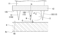
次いで、図4を参照して静翼シールフィン13の詳細な構成について説明する。図4に示すように、本実施形態では3つの静翼シールフィン13のうち、最も上流側に位置する静翼シールフィン13を第一シールフィン13Aとし、最も下流側に位置する静翼シールフィン13を第三シールフィン13Cとする。さらに、これら第一シールフィン13Aと第三シールフィン13Cとの間に位置する静翼シールフィン13を第二シールフィン13Bとする。
これら3つの静翼シールフィン13のうち、第二シールフィン13Bの先端(径方向内側の端部)には、上述した吸込部20に連通する噴出口Hが形成されている。つまり、詳しくは図示しないが、第二シールフィン13Bの内部には、吸込部20と噴出口Hとを連通させる流路が形成されている。ここで、各静翼シールフィン13同士の間に形成される空間Sでは、蒸気の主流(つまり、静翼本体11の周囲を流れる蒸気の流れ)が静翼シールフィン13自体によって阻まれるため、静翼本体11の周囲よりも静圧が低くなる。つまり、当該空間Sと静翼本体11の周囲との間には圧力差が発生する。これにより、上述の吸込部20から噴出口Hに向かって、静翼本体11の周囲の蒸気の一部が吸い込まれる。吸い込まれた蒸気Aは、噴出口Hから噴流Jとなって空間S内に噴き出す。
(動翼の構成)
図2に示すように、動翼8は、ディスク61と、動翼本体81と、外側シュラウド82と、動翼シールフィン83と、を有している。ディスク61は、軸線Acを中心とする環状をなし、ロータ本体6の外周面6Sに取り付けられている。ディスク61の外周側には、複数の動翼本体81が設けられている。これら動翼本体81は周方向に間隔をあけて配列されている。詳しくは図示しないが、それぞれの動翼本体81は、径方向から見て翼型の断面形状を有している。動翼本体81の径方向外側には外側シュラウド82が設けられている。外側シュラウド82は、軸線Acを中心とする環状をなし、複数の動翼本体81を径方向外側から支持している。
図2に示すように、動翼8は、ディスク61と、動翼本体81と、外側シュラウド82と、動翼シールフィン83と、を有している。ディスク61は、軸線Acを中心とする環状をなし、ロータ本体6の外周面6Sに取り付けられている。ディスク61の外周側には、複数の動翼本体81が設けられている。これら動翼本体81は周方向に間隔をあけて配列されている。詳しくは図示しないが、それぞれの動翼本体81は、径方向から見て翼型の断面形状を有している。動翼本体81の径方向外側には外側シュラウド82が設けられている。外側シュラウド82は、軸線Acを中心とする環状をなし、複数の動翼本体81を径方向外側から支持している。
外側シュラウド82の外周面82Sには、軸線Ac方向に間隔をあけて配列された複数の動翼シールフィン83が設けられている。動翼シールフィン83は、外側シュラウド82と内周面3Sとの間に流れ込む蒸気の流れ(漏れ流れ)を抑制する。本実施形態では一例として4つの動翼シールフィン83が設けられている。なお、動翼シールフィン83の数は4つに限定されず、3つ以下や5つ以上であってもよい。それぞれの動翼シールフィン83は、外周面82Sから径方向外側に向かって突出するとともに周方向に延びる環状をなしている。動翼シールフィン83は、径方向内側から外側に向かうに従って軸線Ac方向の寸法が次第に小さくなることでテーパ状の断面形状を有している。動翼シールフィン83の先端(径方向外側の端部)とケーシング3の内周面3Sとの間には一定の隙間(クリアランス)が形成されている。
(作用効果)
続いて、本実施形態に係る蒸気タービン1の動作について説明する。蒸気タービン1を運転するに当たっては、外部のボイラ等で生成された高温高圧の蒸気を蒸気供給口40からケーシング3内に供給する。ケーシング3内に供給された蒸気の大部分は、上流側から下流側に向かって流れる中途で静翼段9、及び動翼段7に交互に接触する。静翼段9は蒸気の流れ方向を変更し、動翼段7への流入角度を適正化する。動翼段7に蒸気が流れ込むことで当該動翼段7を介してロータ2に回転力が与えられる。これにより、ロータ2が軸線Ac回りに回転する。ロータ2の回転エネルギーは、例えば軸端に接続された発電機(不図示)を駆動するために用いられる。最も下流側の動翼段7を通過した蒸気は、蒸気排出口50を通じて外部の復水器等(不図示)に導かれる。
続いて、本実施形態に係る蒸気タービン1の動作について説明する。蒸気タービン1を運転するに当たっては、外部のボイラ等で生成された高温高圧の蒸気を蒸気供給口40からケーシング3内に供給する。ケーシング3内に供給された蒸気の大部分は、上流側から下流側に向かって流れる中途で静翼段9、及び動翼段7に交互に接触する。静翼段9は蒸気の流れ方向を変更し、動翼段7への流入角度を適正化する。動翼段7に蒸気が流れ込むことで当該動翼段7を介してロータ2に回転力が与えられる。これにより、ロータ2が軸線Ac回りに回転する。ロータ2の回転エネルギーは、例えば軸端に接続された発電機(不図示)を駆動するために用いられる。最も下流側の動翼段7を通過した蒸気は、蒸気排出口50を通じて外部の復水器等(不図示)に導かれる。
ところで、静翼本体11の周囲を蒸気が通過する際、蒸気の粘性に伴って、流速の小さい境界層と呼ばれる流れの層が静翼本体11の表面に形成されることが知られている。境界層は特に静翼本体11の負圧面11Bにおける後縁11T側で顕著に発生する。また、静翼本体11の前縁11L付近では、径方向の両端部を起点とする二次流れとしての渦が形成されやすい。これらの事象が生じることで蒸気の円滑な流れが阻害され、蒸気タービン1の効率が低下する虞がある。さらに、上述した静翼シールフィン13とロータ本体6の外周面6Sとの間を流れる蒸気の流れ(漏れ流れ)を低減してタービン効率を向上させたいという要請も存在する。
そこで、本実施形態では、上述した吸込部20を通じて境界層、及び二次流れを吸い込み、噴出口Hから噴流Jとして静翼シールフィン13同士の間の空間Sに供給する構成を採っている。静翼シールフィン13によって囲まれた領域(空間S)では、蒸気の主流が流れる領域(主流路)に比べて静圧が低い。この圧力差に基づいて、静翼本体11の表面に形成された吸込部20から噴出口Hに向かう流れが形成される。この流れに乗って境界層や二次流れとしての蒸気が吸込部20から吸い込まれる。吸込部20から吸い込まれた蒸気は、噴出口Hを通じて静翼シールフィン13同士の間の空間Sに噴き出す。これにより、静翼本体11の表面に形成される境界層や二次流れが低減される。その結果、静翼本体11の周囲におけるエネルギー損失が抑制され、蒸気タービン1の効率をさらに向上させることが可能となる。
さらに、静翼本体11の負圧面11B側では特に境界層や二次流れが形成されやすい傾向にある。上記構成によれば、吸込部20は静翼本体11の前縁11Lよりも負圧面11B側に形成されている。これにより、境界層や二次流れをより効果的に吸い込むことができ、エネルギー損失をさらに低減することができる。また、この構成によれば、吸込部20としての開口部が負圧面11Bのみに限定して形成されていることから、例えば正圧面11Aにも同様の開口部を形成した場合に比べて、静翼本体11の強度低下を回避することもできる。
加えて、負圧面11Bにおける後縁11T側に偏った位置では特に境界層が発達しやすい傾向にある。上記構成によれば、このように境界層が発達しやすい位置に後縁側吸込口22が形成されている。この後縁側吸込口22を通じて境界層が吸い込まれるため、蒸気の流れが負圧面11Bに対して密接に付着した状態となる。これにより、蒸気の流れが円滑化され、蒸気タービン1のエネルギー損失をより一層低減することができる。
さらに加えて、負圧面11Bにおける前縁11L側の径方向内側、及び外側の領域では特に二次流れとしての渦が発生しやすい傾向にある。上記構成によれば、このように二次流れが発生しやすい位置に前縁側吸込口21が形成されている。この前縁側吸込口21を通じて二次流れが吸い込まれるため、蒸気の流れが負圧面11Bに対してさらに密接に付着した状態となる。その結果、蒸気タービン1のエネルギー損失をさらに抑えることができる。
ここで、図4に示すように、空間S内では、静翼シールフィン13とロータ本体6の外周面6Sとの間のクリアランスCから流れ込んだ漏れ流れによって渦Vが形成されている。渦Vは、外周面6Sに沿って上流側から下流側に流れた後、下流側の静翼シールフィン13に沿って径方向外側に向きを変え、さらにノズル内周部材12の内周面12Sに沿って再び上流側に向かって流れる。
上記構成では、軸線Ac方向の一方側から数えて2番目の第二シールフィン13Bの径方向内側の端部に噴出口Hが形成されている。噴出口Hから噴き出される噴流JによってクリアランスCを流れる漏れ流れが阻害され、当該漏れ流れに対して縮流効果を与えることができる。さらに、上述した渦Vに対して、噴流Jによってさらなる旋回力が与えられる。渦Vが発達することによって、空間S内に流れ込む漏れ流れの流量をより一層低減することが可能となる。このように、静翼シールフィン13によるシール性能が向上することで、蒸気タービン1の効率をさらに向上させることができる。
[第一実施形態の変形例]
以上、本開示の第一実施形態について説明した。なお、本開示の要旨を逸脱しない限りにおいて、上記の構成に種々の変更や改修を加えることが可能である。例えば、上記第一実施形態では、前縁側吸込口21が径方向に離間して一対設けられている構成について説明した。しかしながら、第一変形例として図5に示すように、径方向の全域にわたって延びる1つのみの前縁側吸込口21Bを形成することも可能である。この構成によれば、径方向の全域にわたって前縁側吸込口21が形成されていることから、より広い範囲で二次流れを効率的に吸い込むことができる。
以上、本開示の第一実施形態について説明した。なお、本開示の要旨を逸脱しない限りにおいて、上記の構成に種々の変更や改修を加えることが可能である。例えば、上記第一実施形態では、前縁側吸込口21が径方向に離間して一対設けられている構成について説明した。しかしながら、第一変形例として図5に示すように、径方向の全域にわたって延びる1つのみの前縁側吸込口21Bを形成することも可能である。この構成によれば、径方向の全域にわたって前縁側吸込口21が形成されていることから、より広い範囲で二次流れを効率的に吸い込むことができる。
さらに、第二変形例として図6に示すように、前縁側吸込口21を形成せず、後縁側吸込口22のみを形成する構成を採ることも可能である。この構成によれば、前縁側吸込口21が形成されていない分だけ静翼本体11に形成される開口部が削減できることから、境界層の低減を図りつつ静翼本体11の強度低下を最小限に抑えることができる。
加えて、第三変形例として図7に示すように、後縁側吸込口22を形成せずに、前縁側吸込口21のみを形成する構成を採ることも可能である。この構成によれば、二次流れと境界層とを前縁側吸込口21によって同時に吸い込み、低減することができる。また、この場合も静翼本体11に形成される開口部が削減できることから、二次流れと境界層の低減を図りつつ静翼本体11の強度低下を最小限に抑えることができる。
[第二実施形態]
次に、本開示の第二実施形態について、図8を参照して説明する。なお、第一実施形態と同様の構成については同一の符号を付し、詳細な説明を省略する。図8に示すように、本実施形態では、噴出口H1が形成される位置が第一実施形態とは異なっている。
次に、本開示の第二実施形態について、図8を参照して説明する。なお、第一実施形態と同様の構成については同一の符号を付し、詳細な説明を省略する。図8に示すように、本実施形態では、噴出口H1が形成される位置が第一実施形態とは異なっている。
噴出口H1は、ノズル内周部材12の内周面12S上に開口している。より詳細には、噴出口H1は、第一シールフィン13Aと第二シールフィン13Bとの間の空間Sに向かって開口している。さらに具体的には、噴出口H1は、軸線Ac方向において、空間Sにおける第一シールフィン13A側に偏った位置に形成されている。つまり、空間S内で形成される渦Vの流れ方向に沿って噴流Jが形成されることで、渦Vの旋回力を助長することが可能とされている。この噴出口H1は、第一実施形態で説明した吸込部20に対して流路Fを通じて連通している。流路Fはノズル内周部材12を径方向に貫通している。
上記構成によれば、隣り合う静翼シールフィン13同士の間の領域(空間S)に、ノズル内周部材12の内周面12Sに形成された噴出口H1を通じて蒸気を供給することができる。特に、本実施形態では噴出口H1は、軸線Ac方向において、空間Sにおける第一シールフィン13A側に偏った位置に形成されている。これにより、当該空間S内における渦Vの形成が促進されるとともに、その旋回力を高めることができる。この渦Vが発達することによって空間S内に流れ込む漏れ流れの流量が低減され、蒸気タービン1の効率をさらに高めることができる。
以上、本開示の第二実施形態について説明した。なお、本開示の要旨を逸脱しない限りにおいて、上記の構成に種々の変更や改修を加えることが可能である。例えば、噴出口H1の位置は上記の内周面12Sに限定されず、ノズル内周部材12、及び複数の静翼シールフィン13のうち、第一シールフィン13Aよりも下流側の部分であればいかなる位置にも噴出口H1を形成することが可能である。つまり、設計や仕様に応じて、第二シールフィン13Bと第三シールフィン13Cの間の内周面12Sに噴出口H1を形成することも可能である。また、第三シールフィン13C自体に第一実施形態と同様の噴出口Hを併せて形成することも可能である。さらに、第三シールフィン13Cのみに噴出口Hを形成する構成を採ることも可能である。
[第三実施形態]
続いて、本開示の第三実施形態について、図9を参照して説明する。なお、上記の各実施形態と同様の構成については同一の符号を付し、詳細な説明を省略する。図9に示すように、本実施形態では、静翼シールフィン13(第二シールフィン13B)における噴出口H2の形成される位置が第一実施形態とは異なっている。第一実施形態では静翼シールフィン13の先端に噴出口Hが形成されているのに対して、本実施形態では当該静翼シールフィン13における下流側を向く面(下流面13D)に噴出口H2が形成されている。言い換えれば、噴出口H2は、静翼シールフィン13の先端13T(つまり、径方向内側の端部)よりも径方向外側の位置に形成されている。また、静翼シールフィン13の基端13R(つまり、径方向外側の端部)から噴出口H2までの距離は、先端13Tから噴出口H2までの距離よりも大きい。つまり、噴出口H2は、基端13Rよりも先端13T側に近接する位置に形成されている。また、噴出口H2は、噴流Jを径方向内側に向かって噴出できるようにその開口方向が設定されている。
続いて、本開示の第三実施形態について、図9を参照して説明する。なお、上記の各実施形態と同様の構成については同一の符号を付し、詳細な説明を省略する。図9に示すように、本実施形態では、静翼シールフィン13(第二シールフィン13B)における噴出口H2の形成される位置が第一実施形態とは異なっている。第一実施形態では静翼シールフィン13の先端に噴出口Hが形成されているのに対して、本実施形態では当該静翼シールフィン13における下流側を向く面(下流面13D)に噴出口H2が形成されている。言い換えれば、噴出口H2は、静翼シールフィン13の先端13T(つまり、径方向内側の端部)よりも径方向外側の位置に形成されている。また、静翼シールフィン13の基端13R(つまり、径方向外側の端部)から噴出口H2までの距離は、先端13Tから噴出口H2までの距離よりも大きい。つまり、噴出口H2は、基端13Rよりも先端13T側に近接する位置に形成されている。また、噴出口H2は、噴流Jを径方向内側に向かって噴出できるようにその開口方向が設定されている。
上記構成によれば、隣り合う静翼シールフィン13同士の間の領域(空間S:第一実施形態と同様)に、静翼シールフィン13の下流面13Dに形成された噴出口H2を通じて噴流Jとしての蒸気を供給することができる。これにより、当該空間S内における渦の形成が促進される。特に、噴出口H2は、静翼シールフィン13の先端13T(つまり、径方向内側の端部)よりも径方向外側の位置に形成されている。これにより、例えば先端13Tに噴出口H2を形成した場合に比べて、噴流Jを渦の流れにさらになじませることができる。つまり、噴流Jによって渦の旋回力をより一層高め、当該渦を発達させることができる。渦が発達することによって上述のクリアランスCを流れる漏れ流れが低減され、蒸気タービン1の効率をさらに高めることができる。
[第三実施形態の変形例]
以上、本開示の第三実施形態について説明した。なお、本開示の要旨を逸脱しない限りにおいて、上記の構成に種々の変更や改修を加えることが可能である。例えば、第三実施形態の第一変形例として図10に示すように、下流側に向かって噴流Jを噴き出すように噴出口H3の開口方向を設定することも可能である。また、第二変形例として図11に示すように、下流側に噴流Jを噴き出す噴出口H4を基端13R側に近接した位置に形成することも可能である。なお、噴出口H3(H4)の開口方向は、下流側を向く方向成分を含んでいればよく、例えば図12に示すように、下流側に向かうに従って径方向内側に向かって噴流Jが形成されるように開口方向が設定されていてもよい。また、下流側に向かうに従って径方向外側に向かって噴流Jが形成されるように開口方向が設定されていてもよい。これらの構成によれば、渦の形成を促進できることに加えて、空間S内に流れ込む漏れ流れの流量自体をさらに低減することが可能となる。その結果、蒸気タービン1の効率をより一層向上させることができる。
以上、本開示の第三実施形態について説明した。なお、本開示の要旨を逸脱しない限りにおいて、上記の構成に種々の変更や改修を加えることが可能である。例えば、第三実施形態の第一変形例として図10に示すように、下流側に向かって噴流Jを噴き出すように噴出口H3の開口方向を設定することも可能である。また、第二変形例として図11に示すように、下流側に噴流Jを噴き出す噴出口H4を基端13R側に近接した位置に形成することも可能である。なお、噴出口H3(H4)の開口方向は、下流側を向く方向成分を含んでいればよく、例えば図12に示すように、下流側に向かうに従って径方向内側に向かって噴流Jが形成されるように開口方向が設定されていてもよい。また、下流側に向かうに従って径方向外側に向かって噴流Jが形成されるように開口方向が設定されていてもよい。これらの構成によれば、渦の形成を促進できることに加えて、空間S内に流れ込む漏れ流れの流量自体をさらに低減することが可能となる。その結果、蒸気タービン1の効率をより一層向上させることができる。
[各実施形態に共通する変形例]
なお、以上の各実施形態では、蒸気タービン1を例に静翼10の構成について説明した。しかしながら、静翼10に相当する構成(吸込部20、及び噴出口H,H1,H2,H3,H4)の適用対象は蒸気タービン1に限定されず、ガスタービンのタービン部にこれを適用することも可能である。
なお、以上の各実施形態では、蒸気タービン1を例に静翼10の構成について説明した。しかしながら、静翼10に相当する構成(吸込部20、及び噴出口H,H1,H2,H3,H4)の適用対象は蒸気タービン1に限定されず、ガスタービンのタービン部にこれを適用することも可能である。
[付記]
各実施形態に記載の蒸気タービン1は、例えば以下のように把握される。
各実施形態に記載の蒸気タービン1は、例えば以下のように把握される。
(1)第1の態様に係る蒸気タービン1は、軸線Ac回りに回転可能なロータ本体6、及び該ロータ本体6の外周面6Sに沿って周方向に配列された複数の動翼8を有するロータ2と、該ロータ2を覆うケーシング3と、該ケーシング3の内周面3Sに沿って周方向に配列された複数の静翼10と、を備え、前記静翼10は、前記軸線Acに対する径方向に延びるとともに、前記軸線Ac方向の一方側から他方側に向かって流れる作動流体の少なくとも一部を吸い込み可能な吸込部20が表面に形成された静翼本体11と、該静翼本体11の径方向内側に設けられたノズル内周部材12と、該ノズル内周部材12の内周面12Sから径方向内側に向かって突出するとともに、前記軸線Ac方向に間隔をあけて配列された複数のシールフィン(静翼シールフィン13)と、を有し、前記ノズル内周部材12、及び前記シールフィンにおける前記軸線Ac方向の最も一方側の前記シールフィンよりも他方側の部分には、前記吸込部20から導かれた作動流体を噴出する噴出口Hが形成されている。
複数のシールフィン(静翼シールフィン13)によって囲まれた領域では、蒸気の主流が流れる領域(主流路)に比べて静圧が低い。この圧力差に基づいて、静翼本体11の表面に形成された吸込部20から噴出口Hに向かって作動流体の一部が吸い込まれる。これにより、静翼本体11の表面に形成される境界層や二次流れを吸い込むことができる。その結果、静翼本体11の周囲でエネルギー損失の発生を抑制することができる。
(2)第2の態様に係る蒸気タービン1では、前記吸込部20は、前記静翼本体11の前縁11Lよりも負圧面11B側に形成されてもよい。
負圧面11B側では特に境界層や二次流れが形成されやすい傾向にある。上記構成によれば、吸込部20は静翼本体11の前縁11Lよりも負圧面11B側に形成されている。これにより、境界層や二次流れをより効果的に吸い込むことができ、エネルギー損失をさらに低減することができる。
(3)第3の態様に係る蒸気タービン1では、前記吸込部20は、前記静翼本体11の負圧面11Bにおける後縁11T側に偏った位置に形成され、径方向の全域にわたって延びている後縁側吸込口22を有してもよい。
負圧面11Bにおける後縁11T側に偏った位置では特に境界層が発達しやすい傾向にある。上記構成によれば、このように境界層が発達しやすい位置に後縁側吸込口22が形成されている。この後縁側吸込口22を通じて境界層が吸い込まれるため、エネルギー損失をより一層低減することができる。
(4)第4の態様に係る蒸気タービン1では、前記吸込部20は、前記静翼本体11の負圧面11Bにおける前縁11L側に偏った位置に形成され、径方向内側の部分、及び外側の部分の少なくとも一方に位置する前縁側吸込口21を有してもよい。
負圧面11Bにおける前縁11L側の径方向内側、及び外側の領域では特に二次流れとしての渦が発生しやすい傾向にある。上記構成によれば、このように二次流れが発生しやすい位置に前縁側吸込口21が形成されている。この前縁側吸込口21を通じて二次流れが吸い込まれるため、エネルギー損失をさらに抑えることができる。
(5)第5の態様に係る蒸気タービン1では、前記前縁側吸込口21は、径方向の全域にわたって延びてもよい。
上記構成によれば、径方向の全域にわたって前縁側吸込口21が形成されていることから、より広い範囲で二次流れを効率的に吸い込むことができる。
(6)第6の態様に係る蒸気タービン1では、前記噴出口H1は、前記ノズル内周部材12の内周面12Sに形成されてもよい。
上記構成によれば、隣り合うシールフィン(静翼シールフィン13)同士の間の領域(空間S)に、ノズル内周部材12の内周面12Sに形成された噴出口H1を通じて作動流体を供給することができる。これにより、当該領域内における渦の形成を促進することができる。この渦が発達することによって漏れ流れの流通が低減され、蒸気タービン1の効率をさらに高めることができる。
(7)第7の態様に係る蒸気タービン1では、前記噴出口Hは、前記複数のシールフィン(静翼シールフィン13)のうち、前記軸線Ac方向の一方側から数えて2番目以降の前記シールフィンの径方向内側の端部に形成されてもよい。
上記構成によれば、軸線Ac方向の一方側から数えて2番目のシールフィンの径方向内側の端部に噴出口Hが形成されている。これにより、当該シールフィンとロータ本体6との間に形成されるクリアランスを流れる漏れ流れに対して縮流効果を与えることができる。その結果、当該漏れ流れが低減され、蒸気タービン1の効率をさらに向上させることができる。
(8)第8の態様に係る蒸気タービン1では、前記噴出口H2は、前記複数のシールフィン(静翼シールフィン13)のうち、前記軸線Ac方向の一方側から数えて2番目以降の前記シールフィンの前記軸線Ac方向の他方側を向く面に形成され、径方向内側に向かって作動流体を噴出するように構成されてもよい。
上記構成によれば、隣り合うシールフィン同士の間の領域(空間S)に、シールフィンの下流側を向く面に形成された噴出口H2を通じて作動流体を供給することができる。これにより、当該領域内における渦の形成を促進することができる。この渦が発達することによって漏れ流れが低減され、蒸気タービン1の効率をさらに高めることができる。
(9)第9の態様に係る蒸気タービン1では、前記噴出口H3は、前記複数のシールフィンのうち、前記軸線Ac方向の一方側から数えて2番目以降の前記シールフィン(静翼シールフィン13)の前記軸線Ac方向の他方側を向く面に形成され、前記軸線Ac方向の他方側に向かう方向成分を伴って作動流体を噴出するように構成されてもよい。
上記構成によれば、隣り合うシールフィン同士の間の領域(空間S)に、シールフィンの下流側を向く面に形成された噴出口H3を通じて作動流体を供給することができる。特に、作動流体は噴出口H3から下流側に向かう方向成分を伴って噴出される。これにより、当該領域内を通過する漏れ流れをさらに低減することができる。その結果、蒸気タービン1の効率をさらに高めることができる。
本開示によれば、さらに効率が向上した蒸気タービンを提供することができる。
1 蒸気タービン
2 ロータ
3 ケーシング
3S 内周面
4 ジャーナル軸受
5 スラスト軸受
6 ロータ本体
6S 外周面
7 動翼段
8 動翼
9 静翼段
10 静翼
11 静翼本体
11A 正圧面
11B 負圧面
11L 前縁
11T 後縁
12 ノズル内周部材
12S 内周面
13 静翼シールフィン
13A 第一シールフィン
13B 第二シールフィン
13C 第三シールフィン
13D 下流面
13R 基端
13T 先端
20 吸込部
21,21B 前縁側吸込口
22 後縁側吸込口
31 ノズル外周部材
40 蒸気供給口
50 蒸気排出口
61 ディスク
81 動翼本体
82 外側シュラウド
82S 外周面
83 動翼シールフィン
Ac 軸線
C クリアランス
CL キャンバーライン
F 流路
H,H1,H2,H3,H4 噴出口
J 噴流
S 空間
V 渦
Claims (9)
- 軸線回りに回転可能なロータ本体、及び該ロータ本体の外周面に沿って周方向に配列された複数の動翼を有するロータと、
該ロータを覆うケーシングと、
該ケーシングの内周面に沿って周方向に配列された複数の静翼と、
を備え、
前記静翼は、前記軸線に対する径方向に延びるとともに、前記軸線方向の一方側から他方側に向かって流れる作動流体の少なくとも一部を吸い込み可能な吸込部が表面に形成された静翼本体と、
該静翼本体の径方向内側に設けられたノズル内周部材と、
該ノズル内周部材の内周面から径方向内側に向かって突出するとともに、前記軸線方向に間隔をあけて配列された複数のシールフィンと、
を有し、
前記ノズル内周部材、及び前記シールフィンにおける前記軸線方向の最も一方側の前記シールフィンよりも他方側の部分には、前記吸込部から導かれた作動流体を噴出する噴出口が形成されているタービン。 - 前記吸込部は、前記静翼本体の前縁よりも負圧面側に形成されている請求項1に記載のタービン。
- 前記吸込部は、前記静翼本体の負圧面における後縁側に偏った位置に形成され、径方向の全域にわたって延びている後縁側吸込口を有する請求項1又は2に記載のタービン。
- 前記吸込部は、前記静翼本体の負圧面における前縁側に偏った位置に形成され、径方向内側の部分、及び外側の部分の少なくとも一方に位置する前縁側吸込口を有する請求項1から3のいずれか一項に記載のタービン。
- 前記前縁側吸込口は、径方向の全域にわたって延びている請求項4に記載のタービン。
- 前記噴出口は、前記ノズル内周部材の内周面に形成されている請求項1から5のいずれか一項に記載のタービン。
- 前記噴出口は、前記複数のシールフィンのうち、前記軸線方向の一方側から数えて2番目以降の前記シールフィンの径方向内側の端部に形成されている請求項1から6のいずれか一項に記載のタービン。
- 前記噴出口は、前記複数のシールフィンのうち、前記軸線方向の一方側から数えて2番目以降の前記シールフィンの前記軸線方向の他方側を向く面に形成され、径方向内側に向かって作動流体を噴出するように構成されている請求項1から6のいずれか一項に記載のタービン。
- 前記噴出口は、前記複数のシールフィンのうち、前記軸線方向の一方側から数えて2番目以降の前記シールフィンの前記軸線方向の他方側を向く面に形成され、前記軸線方向の他方側に向かう方向成分を伴って作動流体を噴出するように構成されている請求項1から6のいずれか一項に記載のタービン。
Priority Applications (4)
| Application Number | Priority Date | Filing Date | Title |
|---|---|---|---|
| US18/031,275 US20230374907A1 (en) | 2020-11-25 | 2021-10-19 | Turbine |
| JP2022565112A JPWO2022113570A1 (ja) | 2020-11-25 | 2021-10-19 | |
| CN202180070855.XA CN116324126A (zh) | 2020-11-25 | 2021-10-19 | 涡轮机 |
| DE112021004331.5T DE112021004331T5 (de) | 2020-11-25 | 2021-10-19 | Turbine |
Applications Claiming Priority (2)
| Application Number | Priority Date | Filing Date | Title |
|---|---|---|---|
| JP2020-195481 | 2020-11-25 | ||
| JP2020195481 | 2020-11-25 |
Publications (1)
| Publication Number | Publication Date |
|---|---|
| WO2022113570A1 true WO2022113570A1 (ja) | 2022-06-02 |
Family
ID=81754319
Family Applications (1)
| Application Number | Title | Priority Date | Filing Date |
|---|---|---|---|
| PCT/JP2021/038576 WO2022113570A1 (ja) | 2020-11-25 | 2021-10-19 | タービン |
Country Status (5)
| Country | Link |
|---|---|
| US (1) | US20230374907A1 (ja) |
| JP (1) | JPWO2022113570A1 (ja) |
| CN (1) | CN116324126A (ja) |
| DE (1) | DE112021004331T5 (ja) |
| WO (1) | WO2022113570A1 (ja) |
Citations (5)
| Publication number | Priority date | Publication date | Assignee | Title |
|---|---|---|---|---|
| JPH01110812A (ja) * | 1987-10-23 | 1989-04-27 | Hitachi Ltd | 蒸気タービンの静翼構造 |
| JP2013194720A (ja) * | 2012-03-23 | 2013-09-30 | Hitachi Ltd | 蒸気タービン設備 |
| JP2018035783A (ja) * | 2016-09-02 | 2018-03-08 | 三菱日立パワーシステムズ株式会社 | 軸流タービン翼 |
| JP2018138764A (ja) * | 2017-02-24 | 2018-09-06 | 三菱重工業株式会社 | 軸流回転機械、静翼、動翼 |
| JP2019044678A (ja) * | 2017-08-31 | 2019-03-22 | 三菱重工業株式会社 | 蒸気タービンシステム及びコンバインドサイクルプラント |
Family Cites Families (1)
| Publication number | Priority date | Publication date | Assignee | Title |
|---|---|---|---|---|
| JP7062296B2 (ja) | 2019-05-31 | 2022-05-06 | 株式会社エース電研 | 遊技機設備島及びそれを備えた建築物 |
-
2021
- 2021-10-19 JP JP2022565112A patent/JPWO2022113570A1/ja active Pending
- 2021-10-19 DE DE112021004331.5T patent/DE112021004331T5/de active Pending
- 2021-10-19 WO PCT/JP2021/038576 patent/WO2022113570A1/ja active Application Filing
- 2021-10-19 CN CN202180070855.XA patent/CN116324126A/zh active Pending
- 2021-10-19 US US18/031,275 patent/US20230374907A1/en active Pending
Patent Citations (5)
| Publication number | Priority date | Publication date | Assignee | Title |
|---|---|---|---|---|
| JPH01110812A (ja) * | 1987-10-23 | 1989-04-27 | Hitachi Ltd | 蒸気タービンの静翼構造 |
| JP2013194720A (ja) * | 2012-03-23 | 2013-09-30 | Hitachi Ltd | 蒸気タービン設備 |
| JP2018035783A (ja) * | 2016-09-02 | 2018-03-08 | 三菱日立パワーシステムズ株式会社 | 軸流タービン翼 |
| JP2018138764A (ja) * | 2017-02-24 | 2018-09-06 | 三菱重工業株式会社 | 軸流回転機械、静翼、動翼 |
| JP2019044678A (ja) * | 2017-08-31 | 2019-03-22 | 三菱重工業株式会社 | 蒸気タービンシステム及びコンバインドサイクルプラント |
Also Published As
| Publication number | Publication date |
|---|---|
| US20230374907A1 (en) | 2023-11-23 |
| DE112021004331T5 (de) | 2023-06-01 |
| CN116324126A (zh) | 2023-06-23 |
| JPWO2022113570A1 (ja) | 2022-06-02 |
Similar Documents
| Publication | Publication Date | Title |
|---|---|---|
| JP5518597B2 (ja) | タービンエンジンに関するシステム及び装置並びにタービンエンジン用シール | |
| US8202039B2 (en) | Blade shroud with aperture | |
| JP6109197B2 (ja) | ラジアルタービン動翼 | |
| WO2011007467A1 (ja) | インペラおよび回転機械 | |
| JP5524010B2 (ja) | 可変容量タービン | |
| CN102365464B (zh) | 叶轮和旋转机械 | |
| JP2012092825A (ja) | 蒸気タービンの静翼、及びそれを用いた蒸気タービン | |
| JPWO2017168766A1 (ja) | 回転機械翼、過給機、および、これらの流れ場の形成方法 | |
| WO2018124068A1 (ja) | タービン及びガスタービン | |
| US11149549B2 (en) | Blade of steam turbine and steam turbine | |
| WO2019172422A1 (ja) | ディフューザベーン及び遠心圧縮機 | |
| JP2008208753A (ja) | 遠心圧縮機 | |
| JP6019794B2 (ja) | ラジアルタービンロータ、及びこれを備えた可変容量ターボチャージャ | |
| WO2022113570A1 (ja) | タービン | |
| JP2009036112A (ja) | 回転機械の翼 | |
| JPWO2018116394A1 (ja) | ターボチャージャ及びターボチャージャのノズルベーン並びにタービン | |
| JP6864119B2 (ja) | タービン及びターボチャージャ | |
| WO2019107488A1 (ja) | 多段遠心圧縮機、ケーシング及びリターンベーン | |
| JP6803772B2 (ja) | 軸流回転機械、及び、動翼 | |
| EP3456937B1 (en) | Turbocharger | |
| US20230272738A1 (en) | Turbine and turbocharger | |
| JP7235595B2 (ja) | 回転機械 | |
| JP7165804B2 (ja) | ノズルベーン | |
| JP6994976B2 (ja) | タービンの排気室及びタービン | |
| WO2017072844A1 (ja) | 回転機械 |
Legal Events
| Date | Code | Title | Description |
|---|---|---|---|
| 121 | Ep: the epo has been informed by wipo that ep was designated in this application |
Ref document number: 21897548 Country of ref document: EP Kind code of ref document: A1 |
|
| ENP | Entry into the national phase |
Ref document number: 2022565112 Country of ref document: JP Kind code of ref document: A |
|
| 122 | Ep: pct application non-entry in european phase |
Ref document number: 21897548 Country of ref document: EP Kind code of ref document: A1 |