WO2014080814A1 - Dispositif et procédé de conditionnement d'un groupe de produits en forme de feuille dans lequel sont empilés des produits en forme de feuille - Google Patents
Dispositif et procédé de conditionnement d'un groupe de produits en forme de feuille dans lequel sont empilés des produits en forme de feuille Download PDFInfo
- Publication number
- WO2014080814A1 WO2014080814A1 PCT/JP2013/080643 JP2013080643W WO2014080814A1 WO 2014080814 A1 WO2014080814 A1 WO 2014080814A1 JP 2013080643 W JP2013080643 W JP 2013080643W WO 2014080814 A1 WO2014080814 A1 WO 2014080814A1
- Authority
- WO
- WIPO (PCT)
- Prior art keywords
- sheet
- bag
- product group
- mouth
- pusher
- Prior art date
Links
Images


Classifications
-
- B—PERFORMING OPERATIONS; TRANSPORTING
- B65—CONVEYING; PACKING; STORING; HANDLING THIN OR FILAMENTARY MATERIAL
- B65B—MACHINES, APPARATUS OR DEVICES FOR, OR METHODS OF, PACKAGING ARTICLES OR MATERIALS; UNPACKING
- B65B5/00—Packaging individual articles in containers or receptacles, e.g. bags, sacks, boxes, cartons, cans, jars
- B65B5/06—Packaging groups of articles, the groups being treated as single articles
- B65B5/067—Packaging groups of articles, the groups being treated as single articles in bags
-
- B—PERFORMING OPERATIONS; TRANSPORTING
- B65—CONVEYING; PACKING; STORING; HANDLING THIN OR FILAMENTARY MATERIAL
- B65B—MACHINES, APPARATUS OR DEVICES FOR, OR METHODS OF, PACKAGING ARTICLES OR MATERIALS; UNPACKING
- B65B51/00—Devices for, or methods of, sealing or securing package folds or closures; Devices for gathering or twisting wrappers, or necks of bags
- B65B51/10—Applying or generating heat or pressure or combinations thereof
- B65B51/14—Applying or generating heat or pressure or combinations thereof by reciprocating or oscillating members
- B65B51/146—Closing bags
-
- B—PERFORMING OPERATIONS; TRANSPORTING
- B65—CONVEYING; PACKING; STORING; HANDLING THIN OR FILAMENTARY MATERIAL
- B65B—MACHINES, APPARATUS OR DEVICES FOR, OR METHODS OF, PACKAGING ARTICLES OR MATERIALS; UNPACKING
- B65B7/00—Closing containers or receptacles after filling
- B65B7/02—Closing containers or receptacles deformed by, or taking-up shape, of, contents, e.g. bags, sacks
-
- B—PERFORMING OPERATIONS; TRANSPORTING
- B65—CONVEYING; PACKING; STORING; HANDLING THIN OR FILAMENTARY MATERIAL
- B65B—MACHINES, APPARATUS OR DEVICES FOR, OR METHODS OF, PACKAGING ARTICLES OR MATERIALS; UNPACKING
- B65B43/00—Forming, feeding, opening or setting-up containers or receptacles in association with packaging
- B65B43/42—Feeding or positioning bags, boxes, or cartons in the distended, opened, or set-up state; Feeding preformed rigid containers, e.g. tins, capsules, glass tubes, glasses, to the packaging position; Locating containers or receptacles at the filling position; Supporting containers or receptacles during the filling operation
- B65B43/46—Feeding or positioning bags, boxes, or cartons in the distended, opened, or set-up state; Feeding preformed rigid containers, e.g. tins, capsules, glass tubes, glasses, to the packaging position; Locating containers or receptacles at the filling position; Supporting containers or receptacles during the filling operation using grippers
- B65B43/465—Feeding or positioning bags, boxes, or cartons in the distended, opened, or set-up state; Feeding preformed rigid containers, e.g. tins, capsules, glass tubes, glasses, to the packaging position; Locating containers or receptacles at the filling position; Supporting containers or receptacles during the filling operation using grippers for bags
-
- B—PERFORMING OPERATIONS; TRANSPORTING
- B65—CONVEYING; PACKING; STORING; HANDLING THIN OR FILAMENTARY MATERIAL
- B65B—MACHINES, APPARATUS OR DEVICES FOR, OR METHODS OF, PACKAGING ARTICLES OR MATERIALS; UNPACKING
- B65B63/00—Auxiliary devices, not otherwise provided for, for operating on articles or materials to be packaged
- B65B63/02—Auxiliary devices, not otherwise provided for, for operating on articles or materials to be packaged for compressing or compacting articles or materials prior to wrapping or insertion in containers or receptacles
Definitions
- the present invention relates to a packaging apparatus and packaging method for a sheet-like product group in which a plurality of sheet-like products are stacked.
- bulky sheet-like products such as replacement cleaning sheets, disposable diapers, and sanitary napkins
- a plurality of sheet-like products contained in one packaging bag There is. That is, the mouth portion of the packaging bag is sealed by heat sealing or the like while the plurality of sheet-like products are stacked in the thickness direction of the product in the packaging bag. And such packaging is performed by a suitable packaging apparatus.
- Patent Document 1 shows an example of this packaging device.
- the packaging apparatus includes a transport mechanism for transporting a sheet-like product group in which a plurality of sheet-like products are stacked in the thickness direction to a predetermined insertion standby position, and the sheet-like product group transported to the insertion standby position.
- a stop mechanism for inserting the sheet-like product group into the bag body by pushing it into the bag body from the mouth of the packaging bag body, and a seal for sealing the mouth part of the bag body into which the sheet-like product group is inserted.
- the sealing mechanism has a pair of pinching members provided so as to be able to pinch the mouth from both sides, and the mouth in the open state is closed by pinching the mouth with the pair of pinching members, and The mouth is heat-welded in a state of being sandwiched to seal the mouth.
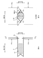
- FIGS. 1A and 1B are explanatory views of the reason why the mouth 5k is wrinkled
- FIG. 1A is a schematic longitudinal sectional view of the bag 5 in which the sheet-like product group 1G is accommodated and the mouth 5k is not sealed. The figure is shown, and the BB arrow line view in FIG. 1A is shown in FIG. 1B.
- the surfaces 5ss, 5ss opposed in the thickness direction in the packaging sheet 5s are welded at both ends 5ew, 5ew in the width direction.
- the opening amount of the mouth 5k is large at the center in the width direction and decreases toward the end.
- the opening amount is different between the center and the end in the width direction.
- the mouth 5k is partially slackened, and the slack turns into wrinkles.
- the mouth 5k is welded in a state in which the eyebrows come close, and the mouth 5k with such eyebrows is not only bad in appearance but also becomes a problem in terms of the sealability of the mouth 5k. .
- the present invention has been made in view of the above-described conventional problems, and its object is to provide a mouth portion of a packaging bag body into which a group of sheet-like products formed by stacking a plurality of sheet-like products is inserted. To prevent wrinkles that may occur when sealing the
- the main invention to achieve the above object is A package in which a sheet-like product group in which a plurality of sheet-like products are stacked in the thickness direction of the sheet-like product is inserted into the packaging bag from the mouth of the packaging bag to seal the mouth A device, A pushing mechanism for inserting the sheet-like product group into the bag body by sliding and pushing the sheet-like product group from the mouth of the packaging bag toward the bottom of the bag; A closing mechanism for closing the mouth by pulling the mouth of the bag in a state in which the sheet-like product group is inserted, in both directions in a cross direction crossing the pressing direction of the pushing mechanism; And a sealing mechanism for sealing the opening in a state of being pulled by the closing mechanism.
- a packaging apparatus for a sheet-like product group in which a plurality of sheet-like products are stacked Also, A package in which a sheet-like product group in which a plurality of sheet-like products are stacked in the thickness direction of the sheet-like product is inserted into the packaging bag from the mouth of the packaging bag to seal the mouth
- Method Inserting the sheet-like product group into the bag body by sliding and pressing the sheet-like product group from the opening of the packaging bag toward the bottom of the bag; Closing the mouth portion by pulling the mouth portion of the packaging bag in a state in which the sheet-like product group is inserted in both directions in a cross direction intersecting the pressing direction of the pushing mechanism; And sealing the opening in a state of being pulled to both sides in the cross direction.
- the wrinkles which may be produced when sealing the opening of the packaging bag body by which the sheet-like product group which the sheet-like products are piled up were inserted can be suppressed.
- FIG. 1A is a schematic longitudinal sectional view of the packaging bag body 5 in which the sheet-like product group 1G is accommodated and the mouth 5k is not sealed
- FIG. 1B is a view taken along the line B-B in FIG. 1A.
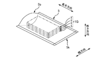
- It is a schematic perspective view of the packaging bag body 5 in which several sheet-like products 1 and 1 ... were accommodated.
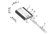
- FIG. 1 is a schematic perspective view of an example of a sheet-like product 1
- FIG. 4A is a schematic plan view of the packaging bag 5
- FIG. 4B is a view as viewed from the arrow BB in FIG. 4A
- FIG. 4C is a view as viewed from the arrow CC in FIG.
- FIG. 4D is a schematic plan view of a state before the film 5 s of the material of the packaging bag 5 becomes the bag 5.
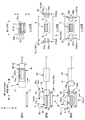
- FIG. 1 is a schematic side view showing the overall configuration of a packaging device 10;
- FIG. 1 is a schematic side view showing the overall configuration of a packaging device 10;
- 7A to 7C are explanatory diagrams of the packaging procedure of the packaging device 10.
- 8A to 8C are explanatory diagrams of the same packaging procedure.
- FIG. 9A and FIG. 9B are explanatory drawings of the same packaging procedure.
- 10A to 10D are explanatory diagrams of the same packaging procedure.
- FIG. 2 is a schematic perspective view of a bucket 24. It is the schematic of an example of the drive mechanism of the movement operation of the up-down direction of a pair of holding claws 54u and 54d.
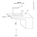
- 5 is a schematic perspective view of a pusher 41.
- a package in which a sheet-like product group in which a plurality of sheet-like products are stacked in the thickness direction of the sheet-like product is inserted into the packaging bag from the mouth of the packaging bag to seal the mouth
- a device A pushing mechanism for inserting the sheet-like product group into the bag body by sliding and pushing the sheet-like product group from the mouth of the packaging bag toward the bottom of the bag;
- a closing mechanism for closing the mouth by pulling the mouth of the bag in a state in which the sheet-like product group is inserted, in both directions in a cross direction crossing the pressing direction of the pushing mechanism;
- a sealing mechanism for sealing the opening in a state of being pulled by the closing mechanism.
- a packaging apparatus by pulling the opening of the packaging bag in a state in which the sheet-like product group is inserted, the opening is closed while partially loosening the opening. And although a mouth part will be in the state where it was crushed almost flat by this, a sealing mechanism seals the mouth part of such a state. Therefore, it becomes possible to suppress wrinkles that may occur when sealing the mouth.
- the mouth has a ridge projecting outward in the cross direction at positions on both sides in the cross direction
- the closing mechanism has gripping portions on both sides in the cross direction, which grips and grips the hook portion in the thickness direction of the hook portion, It is desirable that the opening be pulled to both sides in the cross direction by moving the grips in a state of holding the buttocks outward in the cross direction.
- the mouth is closed by pulling the buttocks respectively provided on both sides of the mouth. Therefore, the tensile force for closing the mouth can be reliably transmitted over the entire length in the cross direction in the mouth, thereby making the mouth substantially flat over the entire length in the cross direction. can do. Then, the sealing mechanism seals the port portion in such a state. Therefore, it becomes possible to more effectively suppress wrinkles that may occur when the sealing mechanism seals the mouth.
- the pushing mechanism has a pusher that reciprocates back and forth along the pushing direction, When the pusher advances toward the bottom of the bag while inserting a portion of the pusher into the bag, the sheet-like product group is pushed into the bag; While leaving the sheet-like product group in the bag, the pusher performs a retraction operation to draw the part of the pusher out of the bag, and the pusher performs the advance operation before it is performed. Return to the position of In the retracting operation, it is desirable that the movement of the bag be restricted by the gripping portion gripping the buttocks.
- the pusher when the pusher retracts, a part of the pusher is pulled backward from the inside of the bag, and accordingly, the pulling force acts on the bag rearward as well, thereby The pulling force may cause the bag to move rearward. That is, the bag may be displaced rearward. Then, there is a risk that the various treatments to be performed on the bag body may be adversely affected thereafter.
- the gripping portion grips the buttocks to restrict the movement of the bag body.
- the rearward displacement of the bag that may occur during the retracting operation is reliably prevented, and as a result, various processes to be performed on the bag after that can be accurately performed.
- the pushing mechanism has a pusher that reciprocates back and forth along the pushing direction, When the pusher advances toward the bottom of the bag while inserting a portion of the pusher into the bag, the sheet-like product group is pushed into the bag; While leaving the sheet-like product group in the bag, the pusher performs a retraction operation to draw the part of the pusher out of the bag, and the pusher performs the advance operation before it is performed.
- the position of It has a pressing member capable of switching between a pressing state in which the bag body in a state in which the sheet-like product group is inserted is pressed from the outside along the thickness direction, and a non-pressing state in which the bag is not pressing. In the reverse operation, the pressing member is preferably set to the pressing state.
- the pushing force acts on the bag rearward as well, thereby The pulling force may cause the bag to move rearward. That is, the bag may be displaced rearward. Then, there is a risk that the various treatments to be performed on the bag body may be adversely affected thereafter.
- the pressing member is in a pressing state during the retracting operation, thereby restricting the movement of the bag.
- the sealing mechanism has a pair of pinching members provided so as to be able to be pinched from both sides in a second cross direction crossing the both the cross direction and the pushing direction.
- the pinching member seals the mouth portion by joining the mouth portion at an inner circumferential surface while pressing the mouth portion, It is desirable that the pressed state of the pressing member be switched to the non-pressed state after the pinching member has pressed the opening.
- the pressing state of the pressing member against the bag is maintained at least until the pinching member presses the opening of the bag. And here, if it is in the pressed state, the recovery phenomenon to the bulky state of the sheet-like product group in the bag which may occur when the sheet-like product group is inserted into the bag in the compressed state, As a result, the opening of the mouth that may occur along with the expansion phenomenon can be effectively suppressed. Therefore, the pinching member of the sealing mechanism can more stably perform the sealing process of the opening.
- the thickness direction of the sheet-like product points in a second intersecting direction intersecting with both the intersecting direction and the pushing direction
- the pusher has a pusher main body whose front end surface abuts against the sheet-like product group at the time of pushing, and a flange portion projecting forward from one end in the thickness direction at the front end surface
- the sheet-shaped product group is arranged along the second crossing direction from the other Having a transport mechanism for transporting toward one side, In the process of transporting the group of sheet-like products to the predetermined position, the transport mechanism compresses the group of sheet-like products in the second intersecting direction in cooperation with the buttocks and in the second intersecting direction It is desirable to push the sheet-like product group into the bag by the pusher while maintaining the sheet-like product group in a compressed state.
- the pusher compresses the sheet-like product group in cooperation with the transport mechanism and pushes the sheet-like product group into the bag while maintaining the compressed state. Therefore, the sheet-like product group can be reliably pushed to the back of the bag, that is, to a position closer to the bottom. And since the sheet-like product group can be located in the position comparatively distant from the mouth by this, the opening effect of the mouth which a sheet-like product group can have on the mouth can be reduced effectively. As a result, it is possible to suppress wrinkles that may occur when sealing the mouth.
- the bag body is formed of one or more sheet materials, and In the sheet material, it is preferable that the ridge portion be formed by joining surfaces which correspond to the inner peripheral surface of the bag and which are opposed to each other at the end in the cross direction. .
- a folded portion of the sheet material forms the bottom of the bag body; It is desirable that the folded portion be folded in an M shape so that the bottom portion can be developed in the thickness direction.
- the bag body may be formed when sealing the mouth even in the case of a so-called standing pouch form in which the bottom can be made to stand up with the ground plane. Can be suppressed.
- the sealing mechanism has a pair of pinching members that can be pinched from both sides in a second crossing direction crossing the opening in both the crossing direction and the pushing direction,
- the pinching member seals the mouth portion by joining the mouth portion at an inner circumferential surface while pressing the mouth portion, It is desirable that the pinching member be disposed at a position farther from the sheet-like product group in the bag body than the grip portion of the closing mechanism in the pushing direction.
- the arrangement position of the pressing member in the pressing direction is a position farther from the sheet-like product group in the bag than the arrangement position of the gripping portion of the closing mechanism. Therefore, a pinching member can clamp and join the part which the holding part fully planarized among the opening parts. And as a result, it is possible to effectively prevent wrinkles that may occur when sealing the mouth.
- a package in which a sheet-like product group in which a plurality of sheet-like products are stacked in the thickness direction of the sheet-like product is inserted into the packaging bag from the mouth of the packaging bag to seal the mouth
- Method Inserting the sheet-like product group into the bag body by sliding and pressing the sheet-like product group from the opening of the packaging bag toward the bottom of the bag; Closing the mouth portion by pulling the mouth portion of the packaging bag in a state in which the sheet-like product group is inserted in both directions in a cross direction intersecting the pressing direction of the pushing mechanism; And sealing the opening in a state of being pulled to both sides in the cross direction.
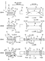
- FIG. 2 is a schematic perspective view of the packaging bag 5 containing a plurality of sheet-like products 1, 1...
- FIG. 3 is a schematic perspective view of an example of the sheet-like product 1.
- 4A is a schematic plan view of the packaging bag 5
- FIG. 4B is a BB arrow view in FIG. 4A
- FIG. 4C is a CC arrow view in FIG. 4A.
- 4D is a schematic plan view of a state before the film 5s of the material of the packaging bag 5 becomes the bag 5.
- FIG. 4A to 4C also show the bag body 5 in which the opening 5k is not sealed.
- the sheet-like product 1 is, for example, a cleaning sheet 1.
- the cleaning sheet 1 includes, for example, a non-woven substrate sheet 2a, a non-woven auxiliary sheet 2b provided to cover the upper surface of the substrate sheet 2a, and a lower surface of the base sheet 2a.
- the packaging bag 5 has a bottom 5b at one end in the longitudinal direction of the bag 5 and a mouth 5k at the other end, for example, It is formed of one flexible thermoplastic resin film 5s (corresponding to a sheet material).
- the planar shape of the film 5s before becoming the bag 5 is, for example, a substantially rectangular shape having a longitudinal direction, a width direction, and a thickness direction as shown in FIG. 4D. Then, the film 5s is folded in half by folding back at the portion 5b corresponding to the bottom portion 5b of the bag body 5, but at this time, as shown in FIG.
- the cross-sectional shape of the folded portion 5b is M
- the film 5s is folded in half so as to form a letter shape, that is, the film 5s is folded in half via the M-shaped folded portion 5b.
- the faces 5ss and 5ss of the films 5s facing each other in this half-folded state are welded and joined along the entire length in the longitudinal direction at both ends 5ew and 5ew in the width direction of the film 5s as shown in FIG. 4A.
- the above-mentioned surfaces 5 ss and 5 ss become the inner peripheral surface
- the folded portion 5 b becomes the bottom 5 b
- the bag body 5 whose end opposite to the bottom 5 b is the mouth 5 k is generated.
- the M-shaped folded portion 5b of the bottom 5b is expanded and spread as shown in FIG. 4C, whereby a substantially planar bottom is formed on the bottom 5b. It is also possible to stand the bag body 5 with the bottom surface as a ground contact surface.
- the surfaces 5ss and 5ss corresponding to the inner peripheral surface of the bag 5 in the film 5s and the faces 5ss and 5ss facing each other are the films 5s. Since welding is carried out at both ends 5ew and 5ew in the width direction, joints 5j and 5j formed at both ends 5ew and 5ew in the welding are not connected from the ends in the width direction of bag 5, respectively. It is like ridges 5j, 5j protruding to the side. That is, the bag body 5 has flange portions 5j, 5j at both end portions 5ew, 5ew in the width direction, and the flange portions 5j, 5j are formed over the entire length in the longitudinal direction.
- the ridges 5j, 5j are formed in this way, the positions of the ridges 5j and the surfaces 5ss, 5ss corresponding to the inner peripheral surface of the mouth 5k with respect to the position in the thickness direction face each other Since both of the intermediate surfaces 5ss and 5ss are substantially coincident with each other (see FIGS. 4B and 4C), the ridges 5j and 5j are opposed to each other by pulling the ridges 5j and 5j to both sides in the width direction. The opening between the faces 5ss and 5ss will close quickly. Therefore, in the packaging apparatus 10 described later, immediately before the sealing process of the opening 5k, the flanges 5j and 5j are pulled to both sides in the width direction to close the opening 5k.
- the thickness direction, the width direction, and the longitudinal direction of the collar portion 5j are parallel to the thickness direction, the width direction, and the longitudinal direction of the film 5s, respectively, and further, the thickness direction of the bag body 5, Both in the width direction and in the longitudinal direction are parallel. Therefore, in the following, the thickness direction, the width direction, and the longitudinal direction according to the film 5s, the bag 5, and the collar 5j are simply distinguished from each other in the "thickness direction", “width direction”. And “longitudinal direction”. Moreover, speaking of the magnitude relationship between the dimensions in these three directions, the dimension in the width direction is larger than the dimension in the thickness direction, and the dimension in the longitudinal direction is larger than the dimension in the width direction.
- the plurality of cleaning sheets 1, 1... Described above are inserted from the opening 5k toward the bottom 5b At this time, a plurality of cleaning sheets 1, 1... Are accommodated in a cleaning sheet group 1G (corresponding to a sheet-like product group) formed by being stacked in the thickness direction of the sheet 1. Further, the cleaning sheet 1 is accommodated so as to be parallel to the thickness direction, the width direction and the longitudinal direction of the bag body 5 in the thickness direction, the width direction and the longitudinal direction, respectively. Then, in the accommodation state, welding is performed by welding on the inner peripheral surface of the opening 5k in a state where the opening 5k of the bag 5 is substantially flatly closed, whereby the opening 5k is sealed. The cleaning sheet group 1 G is in a state of being packaged in the packaging bag 5.
- a cleaning sheet group 1G corresponding to a sheet-like product group
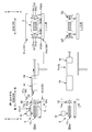
- FIG.5 and FIG.6 is a schematic side view which shows the whole structure of this packaging apparatus 10.
- FIG. 7A to 10D are explanatory diagrams of the packaging procedure of the apparatus 10. 7A to 10D each have a left view and a right view, but here, the left view shows a schematic side view, and the right view shows the left view. The L-L arrow line view of the inside is shown.
- the bag body 5 is seen through and shown.
- the packaging device 10 receives a bag 5 supplied from the manufacturing line L5 of the packaging bag 5 and transfers the bag 5 to a predetermined bag insertion standby position PW5;
- the sheet conveying mechanism 30 for cleaning which conveys the sheet group 1G for cleaning to the sheet group insertion standby position PW1G opposite to the opening 5k of the bag 5 conveyed to the same bag body insertion standby position PW5 (equivalent to a conveyance mechanism) And while cleaning the sheet group 1G for cleaning conveyed to the sheet group insertion standby position PW1G along the pushing direction from the opening 5k of the bag 5 to the bottom 5b of the bag insertion standby position PW5.
- a pushing mechanism 40 for moving the bag body 5 together with the cleaning sheet group 1G to the back side position in the pushing direction with respect to the bag insertion standby position PW5 while pushing in and the back side position A mouth closing mechanism (corresponding to a closing mechanism) 50 for closing the open mouth 5k of the moved bag 5; and a sealing mechanism 60 for sealing the mouth 5k closed by the mouth closing mechanism 50; It has the discharge mechanism 70 which discharges to the following process by conveying the bag body 5 with which the opening part 5k was sealed to the back side of a pushing direction further.
- the configurations 20, 30, 40, 50, 60, and 70 will be described in detail below, but in the following description, three directions orthogonal to one another are defined as the vertical direction, the longitudinal direction, and the lateral direction.
- the vertical direction is the vertical direction
- the front and rear direction and the horizontal direction are respectively the horizontal direction
- the horizontal direction is the direction passing through the sheet of FIG. .
- the present invention is not limited to this, and these three directions may be inclined from the vertical direction or the horizontal direction.
- the above-mentioned pushing direction is made parallel to the front-back direction for convenience of explanation, and the back side of the pushing direction is the front side of the front-back direction, and the near side of the pushing direction is the rear side of the front-back direction
- the pushing direction may be vertical or horizontal.
- this pushing direction corresponds to the "pushing direction” described in the claims, and accordingly, the left-right direction corresponds to the "crossing direction” described in the claims, and the up-down direction corresponds to the claims. It corresponds to the "second cross direction" described in the above.
- the bag transport mechanism 20 has a disc member 22 that rotates about a predetermined rotation axis C22 along the front-rear direction as a main body, and the disc surface on the rear side of the disc member 22 is rotated.
- a plurality of buckets 24, 24... are provided at equal intervals in the circumferential direction along the circumferential line concentric with the axis C22.
- Each bucket 24 is a suitable outer shell member 24 and can cover the outer peripheral surface with the bag 5 and also has a space for passing the cleaning sheet group 1G along the front and rear direction (hereinafter referred to as a passage space) It is a member having the And in this example, since the shape of cleaning sheet group 1G in the section which makes the direction of order normal is the approximately rectangle shape, the section shape of the space for passage inside shell member 24 is also rectangular shape. Meanwhile, the cross-sectional shape of the outer shape of the outer shell member 24 is also rectangular. Specifically, as shown in the schematic perspective view of FIG.
- the buckets 24 have a pair of U-shaped cross-section members (C-shaped cross-section members in Japanese Katakana notation) 24a and 24a, inside each other They are arranged in the left-right direction while facing each other.
- a through hole (not shown) having substantially the same shape along the front-back direction corresponding to the rectangular passage space inside the bucket 24 being formed. It is formed.
- the disc member 22 in FIG. 5 is intermittently rotated around the rotation axis C22 by a suitable drive source such as a servomotor, but here, from the manufacturing line L5 of the packaging bag 5 on the above circumferential line
- a suitable drive source such as a servomotor
- Both the bag body receiving position PR5 for receiving the bag body 5 intermittently sent and the bag body insertion standby position PW5 described above are set. Then, while the bucket 24 is parked at the bag receiving position PR5, the bag 5 is sent from the manufacturing line L5 of the bag 5 in a posture in which the opening 5k is directed forward, and the bucket 24 is parked. From behind.
- the sheet group 1G for cleaning by the above-mentioned pushing mechanism 40 Is pushed into the bucket 24 from the rear, and the further pushing pushes the bag body 5 of the bag body insertion standby position PW5 forward together with the cleaning sheet group 1G, whereby the bag body 5 is removed from the bucket 24. It will be in the state of coming off.
- the bag 5 removed from the bucket 24 is sealed at the mouth 5k by the sealing mechanism 60 or the like, which will be described later.
- the dimensions of the short side LS and the long side LL of this rectangular cross-sectional shape are It is set corresponding to the dimension in the thickness direction and the dimension in the width direction of the bag 5 in a state in which the cleaning sheet group 1G is inserted.
- both the long side LL of the cross sectional shape of the bucket 24 and the width direction of the bag body 5 are parallel to each other, and the short side LS of the same cross sectional shape and the thickness direction of the bag body 5
- the bag 5 is placed on the bucket 24 so that both are parallel to each other.
- the long side LL of the sectional shape of the bucket 24 is directed in the left and right direction, and the short side LS of the same sectional shape is directed in the up and down direction.
- the width direction of the bag 5 is in the left-right direction, and the thickness direction of the bag 5 is in the up-down direction.
- the cleaning sheet group standby position PW1G facing the bag body insertion standby position PW5 as described later, the cleaning sheet group 1G vertically extends in the thickness direction and horizontally in the width direction. And, it stands by in a posture in which the longitudinal direction is directed in the front and back direction. Therefore, when inserting the cleaning sheet group 1G into the bag 5, the respective directions in the thickness direction, the width direction, and the longitudinal direction of the bag 5 and the cleaning sheet group 1G are aligned with each other. Be put in
- the cleaning sheet group transport mechanism 30 has a lift member 32 that moves up and down in the vertical direction.
- the lower limit position P32L of the lift path of the lift member 32 functions as a cleaning sheet group receiving position PR1 for receiving the cleaning sheet group 1G intermittently transported from the manufacturing line L1 of the cleaning sheet 1
- the upper limit position P32U of the elevation path functions as the above-mentioned sheet group insertion standby position PW1G. That is, the upper limit position PW1G functions as a standby position at which the cleaning sheet group 1G waits for the pushing mechanism 40 to push the cleaning sheet group 1G placed on the lift member 32 into the bag 5 of the bucket 24. .
- the cleaning sheet group 1G has the thickness direction in the vertical direction and the width direction in the horizontal direction, with the horizontal upper surface of the lift member 32 as the placement surface, Further, the cleaning sheet group 1G is placed in a posture in which the longitudinal direction is directed in the front-rear direction, and the cleaning sheet group 1G is sent to the above-mentioned sheet group insertion standby position PW1G in this posture.
- the elevating operation of the lift member 32 is performed by an appropriate drive source (not shown) such as a hydraulic cylinder, an air cylinder, a servomotor or the like.
- an appropriate drive source such as a hydraulic cylinder, an air cylinder, a servomotor or the like.
- the pushing mechanism 40 is disposed behind the sheet group insertion standby position PW1G, and has a pusher 41 that reciprocates along the pushing direction, ie, the front-rear direction. And in the state where the pusher 41 is positioned at the reverse limit P41B as shown in FIG. 5, a space having a size corresponding to one part of the cleaning sheet group 1G is formed in front of the pusher 41. Therefore, the lift member 32 ascends with the position of this space as the above-mentioned sheet group insertion standby position PW1G, whereby the cleaning sheet group 1G is interposed at the same sheet group insertion standby position PW1G.
- the forward limit P41F of the pusher 41 is set further forward than the above-mentioned bag body insertion standby position PW5. Therefore, as shown in FIGS. 5 and 6, in the process of the pusher 41 advancing to the forward limit P 41 F, first, the pusher 41 indirectly pushes the cleaning sheet group 1 G into the bucket 24 by pushing it into the bucket 24. The cleaning sheet group 1G is pushed into 5, but by further pushing forward, the bag sheet 5 is also used together with the cleaning sheet group 1G through contact of the cleaning sheet group 1G with the bottom 5b of the bag body 5, etc. Push forward, thereby removing the bag 5 from the bucket 24 forward.
- the pusher 41 further pushes the bag body 5 containing the cleaning sheet group 1G to the position of the front opening closing mechanism 50 and the sealing mechanism 60, and with this, the pusher 41 reaches the advancing limit P41F. ( Figure 6).
- the pusher 41 that has reached the forward limit P41F returns to the reverse limit P41B of FIG. 5 by performing a reverse operation while leaving the cleaning sheet group 1G in the bag 5. Then, the process waits until the next cleaning sheet group 1G is conveyed to the sheet group insertion standby position PW1G.
- the pusher 41 has, for example, a head portion 41h (corresponding to a pusher main body) and a rod portion 41r integrally provided at a rear end portion of the bed portion 41h. Then, the rod portion 41r is given a driving force relating to forward movement and backward movement from a suitable drive source (not shown) such as a servomotor, a hydraulic cylinder, an air cylinder, etc., whereby the pusher 41 moves forward. Move backwards.
- a suitable drive source such as a servomotor, a hydraulic cylinder, an air cylinder, etc.
- the front end surface 41ha of the head portion 41h is formed in a vertical surface. Therefore, when the front end face 41ha abuts on the cleaning sheet group 1G from the rear, the cleaning sheet group 1G can be smoothly pushed forward.
- the head portion 41 h has a plate-like collar portion 41 hc protruding forward from the upper end edge portion of the front end surface 41 ha. Then, when the pusher 41 is positioned at the reverse limit P41B, as shown in FIG. 5, the flange portion 41hc is positioned immediately above the elevating path of the lift member 32. Therefore, when the cleaning sheet group 1G on the lift member 32 is moved to the sheet group insertion standby position PW1G by the upward movement of the lift member 32, the cleaning portion 41hc and the lift member 32 perform cleaning at the end of the movement. The sheet group 1G is compressed. This will be described later.
- the flange portion 41hc of the pusher 41 is located immediately above the cleaning sheet group 1G. Therefore, when the pusher 41 pushes the cleaning sheet group 1G into the bag 5, as shown in FIGS. 8A and 8B, at least the collar 41hc is also inserted into the bag 5. That is, the pusher 41 pushes the sheet-like product group 1G into the bag 5 by performing an advancing operation while inserting a part of the pusher 41 into the bag 5. Further, speaking further, in this example, the whole of the head portion 41 is also inserted into the bag 5, but a part of the head portion 41 may be inserted. .
- Mouth closing mechanism 50 has a pair of left and right grips 52, 52 disposed at a position forward of the bucket 24 of the disk member 22.
- the pusher 41 retracts from the forward limit P41F, all the pushers 41 including the brim portion 41h come out of the bag body 5 remaining in the forward limit P41F, and thereafter these grip portions 52, 52
- the mouth 5k of the bag 5 is pulled to both sides in the left-right direction, thereby closing the mouth 5k and making it in a substantially flat collapsed state.
- the grips 52, 52 selectively grip the portions 5jk, 5jk located in the vicinity of the mouth 5k among the collars 5j, 5j of the bag 5. Then, in the holding state, the holding portions 52, 52 move outward in the left-right direction as shown in the right views of FIGS. 10A and 10B. For example, the left grip 52 moves to the left, and the right grip 52 moves to the right. And thereby, the opening 5k is pulled to the both sides of the width direction which is the left-right direction.
- the moving operation and the gripping operation of the gripping portions 52 in the left-right direction are realized as follows.
- the grips 52, 52 are respectively guided by a suitable guide member (not shown) such as a linear guide so as to be reciprocally movable in the left and right direction, and suitable as servomotors, hydraulic cylinders, air cylinders, etc. It is reciprocated by a drive source (not shown).
- the right and left grips 52, 52 are controlled by an appropriate controller (not shown) so as to reciprocate in the left-right direction in conjunction with each other. That is, as shown in the right views of FIGS.
- the reciprocating movement paths of the left and right grips 52 and 52 are set to be adjacent to the brim 5j and 5j of the bag 5, respectively.
- the approaching positions P52N and P52N and the far positions P52A and P52A set at positions separated from the bag body 5 in the left and right direction from the approaching positions P52N and P52N are set, and one gripping portion 52 is at the approaching position.
- the other gripping portion 52 When moving to P52N, the other gripping portion 52 also moves to the approaching position P52N on its own reciprocation path (FIGS. 8A and 8B), and when one gripping portion 52 moves to the distant position P52A The other grip 52 is also moved to the far position P52A on its own reciprocation path (FIGS. 9A to 10B).
- the gripping portion 52 has a pair of upper and lower gripping claws 54u and 54d provided at positions that can sandwich the brim portion 5j of the bag 5 from both sides in the vertical direction. Then, the pair of gripping claws 54u and 54d slide in the vertical direction interlockingly with each other, thereby performing an opening and closing operation, and in the closed state, the gripping portion holds the collar portion 5j, and in the open state, the collar portion 5j It will be in the non-gripping state which does not hold.
- the bag 5 is held at an intermediate position Pm 54 between the upper gripping claw 54 u and the lower gripping claw 54 d in the open state with respect to the vertical position.
- the pair of upper and lower gripping claws 54u and 54d are arranged such that the portion 5j is positioned, and the moving velocity values in the vertical direction of the gripping claws 54u and 54d are set to be equal to each other. Therefore, the upper gripping claws 54u and the lower gripping claws 54d perform so-called reverse operations with each other in the vertical direction, thereby gripping the collar 5j without generally moving the position of the collar 5j in the vertical direction. Can be done (Fig. 9A).
- each collar part 5j, 5j on the left and the right each has the position of the up-and-down direction It is pulled to the left or right, respectively, while remaining substantially immobile (FIGS. 10A and 10B). Therefore, such a pulling force stably acts on the center position of the mouth 5k in the vertical direction, and as a result, the mouth 5k is quickly closed while taking a partial slack of the mouth 5k, and finally, finally The mouth 5k is almost flatly collapsed (FIG. 10B).
- FIG. 12 is a schematic view showing an example of this drive mechanism with a part broken.
- the drive mechanism includes linear guides 54gu and 54gd for guiding the pair of upper and lower gripping claws 54u and 54d so as to reciprocate independently in the vertical direction, and an air cylinder 54ac as a drive source generating a reciprocating movement in a predetermined direction.
- a pair of link mechanisms 54Lu and 54Ld are provided as operation converting mechanisms for converting the above-mentioned reciprocating movement into movement in the vertical direction and transmitting the movement to the gripping claws 54u and 54d.
- the air cylinder 54ac has a piston 54acp that reciprocates in the left and right direction by, for example, air supply and discharge operations, and the input ends of the pair of link mechanisms 54Lu and 54Ld are connected to the piston 54acp. ing.
- the output end of one link mechanism 54Lu of the pair of link mechanisms 54Lu and 54Ld is connected to the upper gripping claw 54u, while the output end of the other link mechanism 54Ld is lower gripped It is connected to the claw 54d. Therefore, based on the reciprocation movement of one piston 54acp in the left and right direction, the pair of upper and lower gripping claws 54u and 54d move in the vertical direction.
- the portions 54ue and 54ud on the tip side of the gripping claws 54u and 54d are respectively in the form of a gentle curve which is separated from the collar 5j in the vertical direction as it approaches the bag 5 in the horizontal direction. It is bent, so that basically the gripping claws 54u and 54d are designed to grip the flange 5j with the portions 54ub and 54db on the root side thereof. And since it is set as such a gentle curve shape, even when the bag body 5 is likely to be displaced in the horizontal direction as a whole in the process of grasping the collar 5j as shown in FIG. 8C and FIG.
- the 54u, 54d tip side portions 54ue, 54ud such as a gently curved portion 54ue, 54ud abut against the bag 5 so that the bag 5 can be moved in the left-right direction without substantially damaging the bag 5. It can be regulated surely. And thereby, the sealing process which the sealing mechanism 60 performs after this can also be correctly performed without position shift.
- the sealing mechanism 60 is, for example, a heat sealing device 60.
- the heat seal device 60 has a pair of upper and lower seal plates 61u and 61d (corresponding to pinching members) arranged at positions where the opening 5k can be held in the vertical direction.
- the seal plates 61u and 61d are guided so as to be reciprocally movable in the vertical direction by appropriate guide members (not shown) such as linear guides, etc. Further, appropriate members such as servomotors, hydraulic cylinders, air cylinders, etc. It is reciprocated by a drive source (not shown).
- the lower surface 61ua which is the pressing surface of the upper seal plate 61u
- the upper surface 61da which is the pressing surface of the lower seal plate 61d
- the substantially flat port 5k is pressed between the lower surface 61ua of the upper seal plate 61u and the upper surface 61da of the lower seal plate 61d. And it heats in the said pinching state, and, thereby, the opening part 5k is weld-joined by the inner peripheral surface, and is sealed.
- the seal plates 61u and 61d of the sealing mechanism 60 are in the bag 5 more than the grips 52 and 52 of the mouth closing mechanism 50 with respect to the position in the front-rear direction. It is disposed at a position away from the cleaning sheet group 1G, that is, at a position further rearward. And if it arrange
- the arrangement relationship is not limited to this, and in some cases, the positional relationship in the front-rear direction may be reversed as described above.
- the sealing mechanism 60 is not limited to the above-described heat sealing device 60.
- the sealing plates 61u and 61d may perform clamping only without heating the opening 5k, and thereby the opening 5k may be crimped on the inner circumferential surface.
- the adhesive of the hot melt adhesive may be applied to the inner circumferential surface.
- the discharge mechanism 70 is, for example, a belt conveyor 70. Then, the arrangement position of the belt conveyor 70 is set to a position immediately below the bag body 5 containing the cleaning sheet group 1G which is pushed to the forward limit P41F by the pusher 41. Therefore, the bag body 5 containing the cleaning sheet group 1G pushed into the same position is placed on the upper surface of the endless belt 72 of the belt conveyor 70, whereby the sheet 5 is placed on the endless belt 72. In the closed state, the mouth 5k is closed by the above-mentioned mouth closing mechanism 50, and the mouth 5k is sealed by the above-mentioned sealing mechanism 60 (FIG. 10C).
- each of the cleaning sheets 1, 1 ... of the cleaning sheet group 1G is a lift member with the thickness direction in the vertical direction, the width direction in the horizontal direction, and the longitudinal direction in the front and rear direction
- the lower limit position P32L of 32 is reached, and the lower limit position P32L is placed on the lift member 32 at the same position P32L.
- the belt conveyor CVL1 of the manufacturing line L1 for the cleaning sheet 1 is disposed adjacent to the rear of the lift member 32 at the lower limit position P32L and the cleaning sheet group 1G on the belt conveyor CVL1. Is pushed out and supplied to the front lift member 32 by an appropriate push-out mechanism DL1, but the supply mechanism of the cleaning sheet group 1G to the lift member 32 is not limited to this.
- the lift member 32 is raised to the upper limit position P32U, whereby the cleaning sheet group 1G is sent to the above-mentioned sheet group insertion standby position PW1G. Then, in the final stage of the ascending process, as described above, the cleaning sheet group 1G is compressed in the thickness direction by both the flange portion 41hc of the pusher 41 and the lift member 32, thereby the cleaning sheet group The bulk of 1 G is reduced.
- the disk member 22 is intermittently rotated at the same time as or before or after the lifting operation of the lift member 32 described above, whereby the bucket 24 with the bag 5 placed thereon is moved from the bag receiving position PR5 to FIG. It is moved to the bag body insertion standby position PW5 of FIG. 7B. Then, as shown in FIGS. 7C to 8B, the pusher 41 moves forward to the bucket 24 until the forward limit P41F. In this forward operation, the cleaning sheet group 1G is placed on the bottom 5b of the bag 5 The bag 5 is pushed forward as it is by contact, etc., and thereby the bag 5 is detached from the bucket 24 as shown in FIG.
- the compressed state of the cleaning sheet group 1G is maintained by the flange portion 41hc of the pusher 41. Therefore, the cleaning sheet group 1G can be inserted to the back of the bag 5, that is, to a position closer to the bottom 5b of the bag 5 because the bulk is smaller. And thereby, the sheet group 1G for cleaning can be located in the front position further away from the opening 5k, As a result, the opening effect
- the pusher 41 performs a reverse operation to set a reverse limit P41B (to a position before the forward operation).
- the left and right grips 52, 52 located at the above-mentioned far positions P52A, P52A in the open state. Respectively move along the left-right direction so as to approach the bag 5, and the gripping portions 52, 52 stop when reaching the corresponding approach positions P52N, P52N. Then, as shown in FIGS.
- the left and right grips 52, 52 move to the far positions P52A, P52A along the left-right direction so as to separate from the bag 5, respectively.
- the mouth 5k is quickly closed, whereby the mouth 5k is almost flatly crushed (FIG. 10B).
- the pusher 41 is moved from the inside of the bag 5 in the backward movement of the pusher 41 as shown in the left views of FIGS. 9A and 9B.
- the sealing mechanism 60 performs a heat sealing process on the port 5k in a state of being pulled by the grips 52 and 52. That is, the upper seal plate 61u and the lower seal plate 61d respectively move from the both sides in the vertical direction so as to approach the opening 5k, whereby the opening 5k is moved to the upper seal plate 61u and the lower seal plate It is clamped by both 61 d. Then, the opening 5k is heated by the seal plates 61u and 61d in this clamping state, whereby the opening 5k is welded and sealed on the inner peripheral surface.
- the upper seal plate 61u and the lower seal plate 61d move in the vertical direction away from the opening 5k, whereby the upper seal plate 61u and the lower seal are moved from the opening 5k.
- the plate 61d is retracted.
- the gripping portions 52, 52 as shown in FIGS. 10C and 10D, the opening 5k is pinched by the upper and lower seal plates 61u, 61d and is opened at an arbitrary timing thereafter.
- the gripping portions 52, 52 stand by at the far position P52A.
- the belt conveyor 70 serving as the discharge mechanism 70 operates to convey the bag 5 forward, whereby the bag 5 is discharged to the lower process. Then, after discharging, the belt conveyor 70 stops conveyance, and this stopped state is maintained until the next discharging operation.
- the movement of the bag body 5 is restricted by the gripping portions 52, 52 gripping the collar portions 5j, 5j as shown in the right view of FIG. 9A. good.
- the grips 52 and 52 grip the hooks 5j and 5j over the entire period from the start of the retraction operation to the time the entire pusher 41 is pulled out of the bag 5. And if it does in this way, the shift from the target position of the above-mentioned sealing position can be prevented.
- the period during which the eyelids 5j, 5j are gripped in the reverse operation is not limited to the above. That is, the period may be shorter than the above or may be longer than the above. And in either case, the movement control effect of the corresponding bag 5 can be obtained.
- the shape of the flange portion 41hc of the pusher 41 be shaped such that the dimension in the vertical direction becomes smaller toward the front. . Then, according to the collar portion 41hc having such a shape, the cleaning sheet group 1G in the bag 5 is moved rearward together with the pusher 41 when the pusher 41 retracts (for example, FIG. 8C). Can also be suppressed.
- a pressing member 91 is provided at a position immediately above the bag 5 moved to the forward limit P41F by the pusher 41, and the pressing member 91 causes the bag 5 to be viewed from above. It is preferable to be able to switch between a pressed state where pressing is performed and a non-pressed state where pressing is not performed.
- the pressing member 91 can be set in the pressing state in the backward operation of the pusher 41 as shown in FIG. 8C.
- the pressing member 91 can be maintained in the pressed state over the entire period from at least the start of the retraction operation to the point when all the pushers 41 are pulled out of the bag body 5.
- the back of the bag 5 and cleaning sheet group 1G which may occur in the retreating operation of the above-mentioned pusher 41 also by the pressing member 91 concerned.
- the period set to the pressing state in the reverse operation is not limited to the above. That is, the period may be shorter than the above or may be longer than the above. And in either case, the shift control effect of the corresponding bag 5 and cleaning sheet group 1G can be obtained.
- the pressing state of the pressing member 91 is in the non-pressed state after the upper and lower seal plates 61u and 61d of the sealing mechanism 60 sandwich the opening 5k. It is good to be switched to Then, the recovery phenomenon to the bulky state of the cleaning sheet group 1G in the bag body 5 that may occur after pulling out the pusher 41 from the bag body 5, that is, the expansion phenomenon of the cleaning sheet group 1G Thus, it is possible to effectively suppress the opening of the mouth 5k that may occur along with the expansion phenomenon. As a result, the seal plates 61 u and 61 d of the sealing mechanism 60 can perform the sealing process of the port 5 k more stably.
- a predetermined device is applied to the pressing member 91. And according to this device, even when the hook 41hc of the pusher 41 is in the bag 5 as shown in FIG. 8B, the bag 5 and the cleaning sheet group 1G are not pressed without pushing the pusher 41. Only can be selectively pressed.
- a slit-like notch portion SL41 hc is formed at the center position in the left-right direction in the flange portion 41 hc of the pusher 41 as this device. Then, when the pusher 41 is positioned at the forward movement limit P41F, the above-described pressing member 91 is disposed to face directly above the notch portion SL41hc. Therefore, even in the state where the collar portion 41hc of the pusher 41 is in the bag 5, the pressing member 91 can selectively press only the bag 5 and the cleaning sheet group 1G.
- the notch portion SL41hc is formed extending rearward from the front end edge of the collar portion 41hc, that is, the front end edge of the collar portion 41hc is divided by the notch portion SL41hc ing. Therefore, even in the pressing state of the pressing member 91, the pusher 41 can perform the backward operation without any interference with the pressing member 91.
- the switching operation between the pressing state and the non-pressing state of the pressing member 91 is performed by an appropriate drive source (not shown) such as a hydraulic cylinder, an air cylinder, a servomotor or the like.
- an appropriate drive source such as a hydraulic cylinder, an air cylinder, a servomotor or the like.
- a stopper 95 may be provided to restrict the bag body 5 from moving further forward beyond the target stop position.
- the sealing target position of the opening 5k of the bag 5 was positioned at the arrangement position of the seal plates 61u and 61d of the sealing mechanism 60. It will be in the state.
- the stopper 95 has, for example, a plate member 95 that moves up and down in the vertical direction. And if it descends
- the stopper 95 does not face the bottom surface 5b of the bag 5 if it is raised to the upper limit position, so the movement of the bag 5 is not restricted in this state.
- the elevating operation of the stopper 95 is performed by an appropriate driving source (not shown) such as a hydraulic cylinder, an air cylinder, a servomotor, etc. Further, the elevating operation is an advancing operation and a retracting operation of the pusher 41 and a belt conveyor 70 In conjunction with the discharge operation of the For example, the descent operation of the stopper 95 is such that the stopper 95 reaches the lower limit position between the end of the discharge operation of the bag 5 and the next pusher 41 reaching the forward limit P41F. To be done. In addition, the raising operation of the stopper 95 is performed so that the stopper 95 reaches the upper limit position from the start of the retracting operation of the pusher 41 to the start of the discharging operation of the bag body 5.
- an appropriate driving source such as a hydraulic cylinder, an air cylinder, a servomotor, etc.
- the elevating operation is an advancing operation and a retracting operation of the pusher 41 and a belt conveyor 70
- the descent operation of the stopper 95 is such that the stop
- the pair of gripping parts 52, 52 grip the flanges 5j, 5j of the mouth 5k, and the pair of gripping parts 52, 52 are
- the structure which pulls the opening 5k to the both sides of the left-right direction was shown by moving to the both sides of a direction, if it is a mechanism which can pull the opening 5k to both sides, it will not be restricted to this at all.
- a configuration having a pair of left and right suction parts for suctioning and holding the flanges 5j, 5j of the mouth 5k may be used.
- the opening 5k may be pulled to both sides in the left-right direction.
- cleaning sheet 1 was shown as an example of bulky sheet-like product 1, it is not restricted to this at all.
- it may be a disposable diaper or a sanitary napkin, or it may be an individual packaged product in which these are individually packaged.
- the respective buckets 24, 24 ... of the bag transport mechanism 20 are provided and supported by the disk member 22, but the present invention is not limited to the disk member 22 at all.
- a frame member that rotates about a predetermined rotation axis C22 along the front-rear direction may be used as the main body. It is needless to say that openings corresponding to the buckets 24, 24... Are also formed through the frame member in the front-rear direction.
- the thermoplastic resin film 5s is used as the sheet material 5s which is the material of the bag 5, and the bag 5 is formed of one sheet 5s, but the invention is not limited thereto.
- the sheet material 5s may be a non-woven fabric or a woven fabric
- the bag 5 may be formed of a plurality of sheet materials.
- the body portion and the bottom portion may be formed of different sheet materials 5s and 5s, respectively.
- the part may be formed of two sheet materials 5s and 5s.
Abstract
La présente invention concerne un dispositif de conditionnement permettant l'insertion d'un groupe de produits en forme de feuille, dans lequel sont empilés une pluralité de produits en forme de feuille dans le sens de l'épaisseur des produits en forme de feuille, à partir d'une partie ouverture d'un corps de sac de conditionnement vers l'intérieur du corps de sac de conditionnement, et le scellement de la partie ouverture. L'invention comprend : un mécanisme repousseur destiné à pousser le groupe de produits en forme de feuille à partir de la partie ouverture du corps de sac de conditionnement vers la partie inférieure du corps de sac tout en faisant glisser les produits en forme de feuille, et en insérant ainsi le groupe de produits en forme de feuille à l'intérieur du corps de sac ; un mécanisme de fermeture destiné à tirer la partie ouverture du corps de sac, dans un état dans lequel le groupe de produits en forme de feuille a été inséré, vers les deux côtés d'une direction d'intersection intersectant la direction dans laquelle le mécanisme repousseur pousse les produits en forme de feuille vers l'intérieur, et refermant ainsi la partie ouverture ; et un mécanisme de scellement destiné à sceller la partie ouverture dans un état dans lequel elle est tirée par le mécanisme de fermeture.
Applications Claiming Priority (2)
| Application Number | Priority Date | Filing Date | Title |
|---|---|---|---|
| JP2012256424A JP5785925B2 (ja) | 2012-11-22 | 2012-11-22 | 複数のシート状製品が積み重ねられてなるシート状製品群の包装装置、及び包装方法 |
| JP2012-256424 | 2012-11-22 |
Publications (1)
| Publication Number | Publication Date |
|---|---|
| WO2014080814A1 true WO2014080814A1 (fr) | 2014-05-30 |
Family
ID=50775997
Family Applications (1)
| Application Number | Title | Priority Date | Filing Date |
|---|---|---|---|
| PCT/JP2013/080643 WO2014080814A1 (fr) | 2012-11-22 | 2013-11-13 | Dispositif et procédé de conditionnement d'un groupe de produits en forme de feuille dans lequel sont empilés des produits en forme de feuille |
Country Status (2)
| Country | Link |
|---|---|
| JP (1) | JP5785925B2 (fr) |
| WO (1) | WO2014080814A1 (fr) |
Cited By (2)
| Publication number | Priority date | Publication date | Assignee | Title |
|---|---|---|---|---|
| EP3360808A1 (fr) * | 2017-02-14 | 2018-08-15 | Toyo Jidoki Co., Ltd. | Appareil d'insertion |
| CN108423249A (zh) * | 2018-04-12 | 2018-08-21 | 东莞市沃德精密机械有限公司 | 静电袋封装装置 |
Families Citing this family (1)
| Publication number | Priority date | Publication date | Assignee | Title |
|---|---|---|---|---|
| CN112572914A (zh) * | 2020-10-26 | 2021-03-30 | 无锡纯宇环保制品有限公司 | 一种环保购物袋封口机及封口方法 |
Citations (5)
| Publication number | Priority date | Publication date | Assignee | Title |
|---|---|---|---|---|
| JPH03289451A (ja) * | 1990-03-31 | 1991-12-19 | Isao Toyoshima | 流体入りスタンドパックの連続的製法 |
| JP2004142776A (ja) * | 2002-10-24 | 2004-05-20 | Kao Corp | 包装袋開口保持装置及び包装袋開口保持方法 |
| JP2005067644A (ja) * | 2003-08-22 | 2005-03-17 | Toyo Jidoki Co Ltd | 包装物の袋詰めシール方法及び袋詰めシール装置 |
| WO2009107307A1 (fr) * | 2008-02-28 | 2009-09-03 | ユニ・チャーム株式会社 | Elément poussoir dans un dispositif d'emballage |
| JP2010247851A (ja) * | 2009-04-14 | 2010-11-04 | Toyo Jidoki Co Ltd | 袋詰め包装方法 |
Family Cites Families (7)
| Publication number | Priority date | Publication date | Assignee | Title |
|---|---|---|---|---|
| JPH0350003Y2 (fr) * | 1987-08-06 | 1991-10-25 | ||
| JPH11321820A (ja) * | 1998-05-15 | 1999-11-24 | Kao Corp | 袋のシール方法 |
| JP2005035601A (ja) * | 2003-07-14 | 2005-02-10 | Fuji Mach Co Ltd | 袋詰包装機 |
| JP2005075399A (ja) * | 2003-08-29 | 2005-03-24 | Mishima Shokuhin Kk | 熱シール突起形成装置 |
| JP4933927B2 (ja) * | 2007-03-20 | 2012-05-16 | 花王株式会社 | 集積物品のケース投入装置 |
| JP5367354B2 (ja) * | 2008-12-04 | 2013-12-11 | 共同印刷株式会社 | 多室包装袋及びそれを用いた包装体の製造方法 |
| JP5457120B2 (ja) * | 2009-08-31 | 2014-04-02 | 株式会社古川製作所 | 袋詰め装置 |
-
2012
- 2012-11-22 JP JP2012256424A patent/JP5785925B2/ja not_active Expired - Fee Related
-
2013
- 2013-11-13 WO PCT/JP2013/080643 patent/WO2014080814A1/fr active Application Filing
Patent Citations (5)
| Publication number | Priority date | Publication date | Assignee | Title |
|---|---|---|---|---|
| JPH03289451A (ja) * | 1990-03-31 | 1991-12-19 | Isao Toyoshima | 流体入りスタンドパックの連続的製法 |
| JP2004142776A (ja) * | 2002-10-24 | 2004-05-20 | Kao Corp | 包装袋開口保持装置及び包装袋開口保持方法 |
| JP2005067644A (ja) * | 2003-08-22 | 2005-03-17 | Toyo Jidoki Co Ltd | 包装物の袋詰めシール方法及び袋詰めシール装置 |
| WO2009107307A1 (fr) * | 2008-02-28 | 2009-09-03 | ユニ・チャーム株式会社 | Elément poussoir dans un dispositif d'emballage |
| JP2010247851A (ja) * | 2009-04-14 | 2010-11-04 | Toyo Jidoki Co Ltd | 袋詰め包装方法 |
Cited By (6)
| Publication number | Priority date | Publication date | Assignee | Title |
|---|---|---|---|---|
| EP3360808A1 (fr) * | 2017-02-14 | 2018-08-15 | Toyo Jidoki Co., Ltd. | Appareil d'insertion |
| US20180229873A1 (en) * | 2017-02-14 | 2018-08-16 | Toyo Jidoki Co., Ltd. | Insertion apparatus |
| JP2018131269A (ja) * | 2017-02-14 | 2018-08-23 | 東洋自動機株式会社 | 挿入装置 |
| US10654602B2 (en) | 2017-02-14 | 2020-05-19 | Toyo Jidoki Co., Ltd. | Insertion apparatus |
| CN108423249A (zh) * | 2018-04-12 | 2018-08-21 | 东莞市沃德精密机械有限公司 | 静电袋封装装置 |
| CN108423249B (zh) * | 2018-04-12 | 2023-10-20 | 东莞市沃德精密机械有限公司 | 静电袋封装装置 |
Also Published As
| Publication number | Publication date |
|---|---|
| JP5785925B2 (ja) | 2015-09-30 |
| JP2014101147A (ja) | 2014-06-05 |
Similar Documents
| Publication | Publication Date | Title |
|---|---|---|
| TWI478847B (zh) | Pushing device for packaging equipment | |
| CN109153467A (zh) | 由双侧打开的包装套形成单侧打开的包装体的方法和装置 | |
| JP5041273B2 (ja) | 容器包装装置 | |
| KR102118889B1 (ko) | 에어백 부착 자루에 대한 기체봉입방법 및 기체봉입장치 | |
| US11679906B2 (en) | Packaging apparatus with package dividing seal mechanism | |
| ITUB201561098U1 (it) | Apparecchiatura per il confezionamento di un prodotto in un rispettivo involucro preformato | |
| WO2014080814A1 (fr) | Dispositif et procédé de conditionnement d'un groupe de produits en forme de feuille dans lequel sont empilés des produits en forme de feuille | |
| US11352158B2 (en) | Machine for forming packages from a web of preformed bags | |
| JP2005506248A (ja) | 真空包装用の装置および方法 | |
| JP2020525364A (ja) | 揺動グリッパを使用して片側が開口している包装体本体を形成するための方法および装置 | |
| RU2758144C2 (ru) | Полотно пакетов, способ и оборудование для упаковки изделий | |
| WO1998004458A1 (fr) | Appareil d'emballage | |
| JP2007030987A (ja) | 袋詰め包装方法 | |
| NO155924B (no) | Posefyller for pakkemaskin. | |
| JP6647661B2 (ja) | 培地充填袋の折曲げ装置 | |
| EP3634876B1 (fr) | Bandes de sacs préformés | |
| CN110723371A (zh) | 一种手套折叠封装装置 | |
| TWM626368U (zh) | 口罩包裝機 | |
| JP6334283B2 (ja) | 包装機及び包装方法 | |
| TWM552004U (zh) | 包裝袋束條及排氣閥安裝機 | |
| CN110914159B (zh) | 用于操作用热塑性膜包装产品的机器的工艺 | |
| JP2003072702A (ja) | 横型袋包装機における脱気装置 | |
| US11851226B2 (en) | Device for sealing three-dimensional objects in the bag opening of a film bag | |
| JPH05201427A (ja) | 二重連続包装方法及びその装置 | |
| JP2014189332A (ja) | 袋詰品シール方法および装置 |
Legal Events
| Date | Code | Title | Description |
|---|---|---|---|
| 121 | Ep: the epo has been informed by wipo that ep was designated in this application |
Ref document number: 13856551 Country of ref document: EP Kind code of ref document: A1 |
|
| NENP | Non-entry into the national phase |
Ref country code: DE |
|
| 122 | Ep: pct application non-entry in european phase |
Ref document number: 13856551 Country of ref document: EP Kind code of ref document: A1 |