WO2014080814A1 - Device and method for packaging sheet-shaped product group in which plurality of sheet-shaped products are stacked - Google Patents
Device and method for packaging sheet-shaped product group in which plurality of sheet-shaped products are stacked Download PDFInfo
- Publication number
- WO2014080814A1 WO2014080814A1 PCT/JP2013/080643 JP2013080643W WO2014080814A1 WO 2014080814 A1 WO2014080814 A1 WO 2014080814A1 JP 2013080643 W JP2013080643 W JP 2013080643W WO 2014080814 A1 WO2014080814 A1 WO 2014080814A1
- Authority
- WO
- WIPO (PCT)
- Prior art keywords
- sheet
- bag
- product group
- mouth
- pusher
- Prior art date
Links
Images


Classifications
-
- B—PERFORMING OPERATIONS; TRANSPORTING
- B65—CONVEYING; PACKING; STORING; HANDLING THIN OR FILAMENTARY MATERIAL
- B65B—MACHINES, APPARATUS OR DEVICES FOR, OR METHODS OF, PACKAGING ARTICLES OR MATERIALS; UNPACKING
- B65B5/00—Packaging individual articles in containers or receptacles, e.g. bags, sacks, boxes, cartons, cans, jars
- B65B5/06—Packaging groups of articles, the groups being treated as single articles
- B65B5/067—Packaging groups of articles, the groups being treated as single articles in bags
-
- B—PERFORMING OPERATIONS; TRANSPORTING
- B65—CONVEYING; PACKING; STORING; HANDLING THIN OR FILAMENTARY MATERIAL
- B65B—MACHINES, APPARATUS OR DEVICES FOR, OR METHODS OF, PACKAGING ARTICLES OR MATERIALS; UNPACKING
- B65B51/00—Devices for, or methods of, sealing or securing package folds or closures; Devices for gathering or twisting wrappers, or necks of bags
- B65B51/10—Applying or generating heat or pressure or combinations thereof
- B65B51/14—Applying or generating heat or pressure or combinations thereof by reciprocating or oscillating members
- B65B51/146—Closing bags
-
- B—PERFORMING OPERATIONS; TRANSPORTING
- B65—CONVEYING; PACKING; STORING; HANDLING THIN OR FILAMENTARY MATERIAL
- B65B—MACHINES, APPARATUS OR DEVICES FOR, OR METHODS OF, PACKAGING ARTICLES OR MATERIALS; UNPACKING
- B65B7/00—Closing containers or receptacles after filling
- B65B7/02—Closing containers or receptacles deformed by, or taking-up shape, of, contents, e.g. bags, sacks
-
- B—PERFORMING OPERATIONS; TRANSPORTING
- B65—CONVEYING; PACKING; STORING; HANDLING THIN OR FILAMENTARY MATERIAL
- B65B—MACHINES, APPARATUS OR DEVICES FOR, OR METHODS OF, PACKAGING ARTICLES OR MATERIALS; UNPACKING
- B65B43/00—Forming, feeding, opening or setting-up containers or receptacles in association with packaging
- B65B43/42—Feeding or positioning bags, boxes, or cartons in the distended, opened, or set-up state; Feeding preformed rigid containers, e.g. tins, capsules, glass tubes, glasses, to the packaging position; Locating containers or receptacles at the filling position; Supporting containers or receptacles during the filling operation
- B65B43/46—Feeding or positioning bags, boxes, or cartons in the distended, opened, or set-up state; Feeding preformed rigid containers, e.g. tins, capsules, glass tubes, glasses, to the packaging position; Locating containers or receptacles at the filling position; Supporting containers or receptacles during the filling operation using grippers
- B65B43/465—Feeding or positioning bags, boxes, or cartons in the distended, opened, or set-up state; Feeding preformed rigid containers, e.g. tins, capsules, glass tubes, glasses, to the packaging position; Locating containers or receptacles at the filling position; Supporting containers or receptacles during the filling operation using grippers for bags
-
- B—PERFORMING OPERATIONS; TRANSPORTING
- B65—CONVEYING; PACKING; STORING; HANDLING THIN OR FILAMENTARY MATERIAL
- B65B—MACHINES, APPARATUS OR DEVICES FOR, OR METHODS OF, PACKAGING ARTICLES OR MATERIALS; UNPACKING
- B65B63/00—Auxiliary devices, not otherwise provided for, for operating on articles or materials to be packaged
- B65B63/02—Auxiliary devices, not otherwise provided for, for operating on articles or materials to be packaged for compressing or compacting articles or materials prior to wrapping or insertion in containers or receptacles
Definitions
- the present invention relates to a packaging apparatus and packaging method for a sheet-like product group in which a plurality of sheet-like products are stacked.
- bulky sheet-like products such as replacement cleaning sheets, disposable diapers, and sanitary napkins
- a plurality of sheet-like products contained in one packaging bag There is. That is, the mouth portion of the packaging bag is sealed by heat sealing or the like while the plurality of sheet-like products are stacked in the thickness direction of the product in the packaging bag. And such packaging is performed by a suitable packaging apparatus.
- Patent Document 1 shows an example of this packaging device.
- the packaging apparatus includes a transport mechanism for transporting a sheet-like product group in which a plurality of sheet-like products are stacked in the thickness direction to a predetermined insertion standby position, and the sheet-like product group transported to the insertion standby position.
- a stop mechanism for inserting the sheet-like product group into the bag body by pushing it into the bag body from the mouth of the packaging bag body, and a seal for sealing the mouth part of the bag body into which the sheet-like product group is inserted.
- the sealing mechanism has a pair of pinching members provided so as to be able to pinch the mouth from both sides, and the mouth in the open state is closed by pinching the mouth with the pair of pinching members, and The mouth is heat-welded in a state of being sandwiched to seal the mouth.
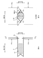
- FIGS. 1A and 1B are explanatory views of the reason why the mouth 5k is wrinkled
- FIG. 1A is a schematic longitudinal sectional view of the bag 5 in which the sheet-like product group 1G is accommodated and the mouth 5k is not sealed. The figure is shown, and the BB arrow line view in FIG. 1A is shown in FIG. 1B.
- the surfaces 5ss, 5ss opposed in the thickness direction in the packaging sheet 5s are welded at both ends 5ew, 5ew in the width direction.
- the opening amount of the mouth 5k is large at the center in the width direction and decreases toward the end.
- the opening amount is different between the center and the end in the width direction.
- the mouth 5k is partially slackened, and the slack turns into wrinkles.
- the mouth 5k is welded in a state in which the eyebrows come close, and the mouth 5k with such eyebrows is not only bad in appearance but also becomes a problem in terms of the sealability of the mouth 5k. .
- the present invention has been made in view of the above-described conventional problems, and its object is to provide a mouth portion of a packaging bag body into which a group of sheet-like products formed by stacking a plurality of sheet-like products is inserted. To prevent wrinkles that may occur when sealing the
- the main invention to achieve the above object is A package in which a sheet-like product group in which a plurality of sheet-like products are stacked in the thickness direction of the sheet-like product is inserted into the packaging bag from the mouth of the packaging bag to seal the mouth A device, A pushing mechanism for inserting the sheet-like product group into the bag body by sliding and pushing the sheet-like product group from the mouth of the packaging bag toward the bottom of the bag; A closing mechanism for closing the mouth by pulling the mouth of the bag in a state in which the sheet-like product group is inserted, in both directions in a cross direction crossing the pressing direction of the pushing mechanism; And a sealing mechanism for sealing the opening in a state of being pulled by the closing mechanism.
- a packaging apparatus for a sheet-like product group in which a plurality of sheet-like products are stacked Also, A package in which a sheet-like product group in which a plurality of sheet-like products are stacked in the thickness direction of the sheet-like product is inserted into the packaging bag from the mouth of the packaging bag to seal the mouth
- Method Inserting the sheet-like product group into the bag body by sliding and pressing the sheet-like product group from the opening of the packaging bag toward the bottom of the bag; Closing the mouth portion by pulling the mouth portion of the packaging bag in a state in which the sheet-like product group is inserted in both directions in a cross direction intersecting the pressing direction of the pushing mechanism; And sealing the opening in a state of being pulled to both sides in the cross direction.
- the wrinkles which may be produced when sealing the opening of the packaging bag body by which the sheet-like product group which the sheet-like products are piled up were inserted can be suppressed.
- FIG. 1A is a schematic longitudinal sectional view of the packaging bag body 5 in which the sheet-like product group 1G is accommodated and the mouth 5k is not sealed
- FIG. 1B is a view taken along the line B-B in FIG. 1A.
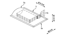
- It is a schematic perspective view of the packaging bag body 5 in which several sheet-like products 1 and 1 ... were accommodated.
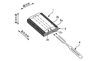
- FIG. 1 is a schematic perspective view of an example of a sheet-like product 1
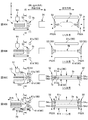
- FIG. 4A is a schematic plan view of the packaging bag 5
- FIG. 4B is a view as viewed from the arrow BB in FIG. 4A
- FIG. 4C is a view as viewed from the arrow CC in FIG.
- FIG. 4D is a schematic plan view of a state before the film 5 s of the material of the packaging bag 5 becomes the bag 5.
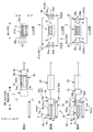
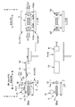
- FIG. 1 is a schematic side view showing the overall configuration of a packaging device 10;
- FIG. 1 is a schematic side view showing the overall configuration of a packaging device 10;
- 7A to 7C are explanatory diagrams of the packaging procedure of the packaging device 10.
- 8A to 8C are explanatory diagrams of the same packaging procedure.
- FIG. 9A and FIG. 9B are explanatory drawings of the same packaging procedure.
- 10A to 10D are explanatory diagrams of the same packaging procedure.
- FIG. 2 is a schematic perspective view of a bucket 24. It is the schematic of an example of the drive mechanism of the movement operation of the up-down direction of a pair of holding claws 54u and 54d.
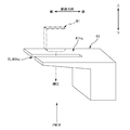
- 5 is a schematic perspective view of a pusher 41.
- a package in which a sheet-like product group in which a plurality of sheet-like products are stacked in the thickness direction of the sheet-like product is inserted into the packaging bag from the mouth of the packaging bag to seal the mouth
- a device A pushing mechanism for inserting the sheet-like product group into the bag body by sliding and pushing the sheet-like product group from the mouth of the packaging bag toward the bottom of the bag;
- a closing mechanism for closing the mouth by pulling the mouth of the bag in a state in which the sheet-like product group is inserted, in both directions in a cross direction crossing the pressing direction of the pushing mechanism;
- a sealing mechanism for sealing the opening in a state of being pulled by the closing mechanism.
- a packaging apparatus by pulling the opening of the packaging bag in a state in which the sheet-like product group is inserted, the opening is closed while partially loosening the opening. And although a mouth part will be in the state where it was crushed almost flat by this, a sealing mechanism seals the mouth part of such a state. Therefore, it becomes possible to suppress wrinkles that may occur when sealing the mouth.
- the mouth has a ridge projecting outward in the cross direction at positions on both sides in the cross direction
- the closing mechanism has gripping portions on both sides in the cross direction, which grips and grips the hook portion in the thickness direction of the hook portion, It is desirable that the opening be pulled to both sides in the cross direction by moving the grips in a state of holding the buttocks outward in the cross direction.
- the mouth is closed by pulling the buttocks respectively provided on both sides of the mouth. Therefore, the tensile force for closing the mouth can be reliably transmitted over the entire length in the cross direction in the mouth, thereby making the mouth substantially flat over the entire length in the cross direction. can do. Then, the sealing mechanism seals the port portion in such a state. Therefore, it becomes possible to more effectively suppress wrinkles that may occur when the sealing mechanism seals the mouth.
- the pushing mechanism has a pusher that reciprocates back and forth along the pushing direction, When the pusher advances toward the bottom of the bag while inserting a portion of the pusher into the bag, the sheet-like product group is pushed into the bag; While leaving the sheet-like product group in the bag, the pusher performs a retraction operation to draw the part of the pusher out of the bag, and the pusher performs the advance operation before it is performed. Return to the position of In the retracting operation, it is desirable that the movement of the bag be restricted by the gripping portion gripping the buttocks.
- the pusher when the pusher retracts, a part of the pusher is pulled backward from the inside of the bag, and accordingly, the pulling force acts on the bag rearward as well, thereby The pulling force may cause the bag to move rearward. That is, the bag may be displaced rearward. Then, there is a risk that the various treatments to be performed on the bag body may be adversely affected thereafter.
- the gripping portion grips the buttocks to restrict the movement of the bag body.
- the rearward displacement of the bag that may occur during the retracting operation is reliably prevented, and as a result, various processes to be performed on the bag after that can be accurately performed.
- the pushing mechanism has a pusher that reciprocates back and forth along the pushing direction, When the pusher advances toward the bottom of the bag while inserting a portion of the pusher into the bag, the sheet-like product group is pushed into the bag; While leaving the sheet-like product group in the bag, the pusher performs a retraction operation to draw the part of the pusher out of the bag, and the pusher performs the advance operation before it is performed.
- the position of It has a pressing member capable of switching between a pressing state in which the bag body in a state in which the sheet-like product group is inserted is pressed from the outside along the thickness direction, and a non-pressing state in which the bag is not pressing. In the reverse operation, the pressing member is preferably set to the pressing state.
- the pushing force acts on the bag rearward as well, thereby The pulling force may cause the bag to move rearward. That is, the bag may be displaced rearward. Then, there is a risk that the various treatments to be performed on the bag body may be adversely affected thereafter.
- the pressing member is in a pressing state during the retracting operation, thereby restricting the movement of the bag.
- the sealing mechanism has a pair of pinching members provided so as to be able to be pinched from both sides in a second cross direction crossing the both the cross direction and the pushing direction.
- the pinching member seals the mouth portion by joining the mouth portion at an inner circumferential surface while pressing the mouth portion, It is desirable that the pressed state of the pressing member be switched to the non-pressed state after the pinching member has pressed the opening.
- the pressing state of the pressing member against the bag is maintained at least until the pinching member presses the opening of the bag. And here, if it is in the pressed state, the recovery phenomenon to the bulky state of the sheet-like product group in the bag which may occur when the sheet-like product group is inserted into the bag in the compressed state, As a result, the opening of the mouth that may occur along with the expansion phenomenon can be effectively suppressed. Therefore, the pinching member of the sealing mechanism can more stably perform the sealing process of the opening.
- the thickness direction of the sheet-like product points in a second intersecting direction intersecting with both the intersecting direction and the pushing direction
- the pusher has a pusher main body whose front end surface abuts against the sheet-like product group at the time of pushing, and a flange portion projecting forward from one end in the thickness direction at the front end surface
- the sheet-shaped product group is arranged along the second crossing direction from the other Having a transport mechanism for transporting toward one side, In the process of transporting the group of sheet-like products to the predetermined position, the transport mechanism compresses the group of sheet-like products in the second intersecting direction in cooperation with the buttocks and in the second intersecting direction It is desirable to push the sheet-like product group into the bag by the pusher while maintaining the sheet-like product group in a compressed state.
- the pusher compresses the sheet-like product group in cooperation with the transport mechanism and pushes the sheet-like product group into the bag while maintaining the compressed state. Therefore, the sheet-like product group can be reliably pushed to the back of the bag, that is, to a position closer to the bottom. And since the sheet-like product group can be located in the position comparatively distant from the mouth by this, the opening effect of the mouth which a sheet-like product group can have on the mouth can be reduced effectively. As a result, it is possible to suppress wrinkles that may occur when sealing the mouth.
- the bag body is formed of one or more sheet materials, and In the sheet material, it is preferable that the ridge portion be formed by joining surfaces which correspond to the inner peripheral surface of the bag and which are opposed to each other at the end in the cross direction. .
- a folded portion of the sheet material forms the bottom of the bag body; It is desirable that the folded portion be folded in an M shape so that the bottom portion can be developed in the thickness direction.
- the bag body may be formed when sealing the mouth even in the case of a so-called standing pouch form in which the bottom can be made to stand up with the ground plane. Can be suppressed.
- the sealing mechanism has a pair of pinching members that can be pinched from both sides in a second crossing direction crossing the opening in both the crossing direction and the pushing direction,
- the pinching member seals the mouth portion by joining the mouth portion at an inner circumferential surface while pressing the mouth portion, It is desirable that the pinching member be disposed at a position farther from the sheet-like product group in the bag body than the grip portion of the closing mechanism in the pushing direction.
- the arrangement position of the pressing member in the pressing direction is a position farther from the sheet-like product group in the bag than the arrangement position of the gripping portion of the closing mechanism. Therefore, a pinching member can clamp and join the part which the holding part fully planarized among the opening parts. And as a result, it is possible to effectively prevent wrinkles that may occur when sealing the mouth.
- a package in which a sheet-like product group in which a plurality of sheet-like products are stacked in the thickness direction of the sheet-like product is inserted into the packaging bag from the mouth of the packaging bag to seal the mouth
- Method Inserting the sheet-like product group into the bag body by sliding and pressing the sheet-like product group from the opening of the packaging bag toward the bottom of the bag; Closing the mouth portion by pulling the mouth portion of the packaging bag in a state in which the sheet-like product group is inserted in both directions in a cross direction intersecting the pressing direction of the pushing mechanism; And sealing the opening in a state of being pulled to both sides in the cross direction.
- FIG. 2 is a schematic perspective view of the packaging bag 5 containing a plurality of sheet-like products 1, 1...
- FIG. 3 is a schematic perspective view of an example of the sheet-like product 1.
- 4A is a schematic plan view of the packaging bag 5
- FIG. 4B is a BB arrow view in FIG. 4A
- FIG. 4C is a CC arrow view in FIG. 4A.
- 4D is a schematic plan view of a state before the film 5s of the material of the packaging bag 5 becomes the bag 5.
- FIG. 4A to 4C also show the bag body 5 in which the opening 5k is not sealed.
- the sheet-like product 1 is, for example, a cleaning sheet 1.
- the cleaning sheet 1 includes, for example, a non-woven substrate sheet 2a, a non-woven auxiliary sheet 2b provided to cover the upper surface of the substrate sheet 2a, and a lower surface of the base sheet 2a.
- the packaging bag 5 has a bottom 5b at one end in the longitudinal direction of the bag 5 and a mouth 5k at the other end, for example, It is formed of one flexible thermoplastic resin film 5s (corresponding to a sheet material).
- the planar shape of the film 5s before becoming the bag 5 is, for example, a substantially rectangular shape having a longitudinal direction, a width direction, and a thickness direction as shown in FIG. 4D. Then, the film 5s is folded in half by folding back at the portion 5b corresponding to the bottom portion 5b of the bag body 5, but at this time, as shown in FIG.
- the cross-sectional shape of the folded portion 5b is M
- the film 5s is folded in half so as to form a letter shape, that is, the film 5s is folded in half via the M-shaped folded portion 5b.
- the faces 5ss and 5ss of the films 5s facing each other in this half-folded state are welded and joined along the entire length in the longitudinal direction at both ends 5ew and 5ew in the width direction of the film 5s as shown in FIG. 4A.
- the above-mentioned surfaces 5 ss and 5 ss become the inner peripheral surface
- the folded portion 5 b becomes the bottom 5 b
- the bag body 5 whose end opposite to the bottom 5 b is the mouth 5 k is generated.
- the M-shaped folded portion 5b of the bottom 5b is expanded and spread as shown in FIG. 4C, whereby a substantially planar bottom is formed on the bottom 5b. It is also possible to stand the bag body 5 with the bottom surface as a ground contact surface.
- the surfaces 5ss and 5ss corresponding to the inner peripheral surface of the bag 5 in the film 5s and the faces 5ss and 5ss facing each other are the films 5s. Since welding is carried out at both ends 5ew and 5ew in the width direction, joints 5j and 5j formed at both ends 5ew and 5ew in the welding are not connected from the ends in the width direction of bag 5, respectively. It is like ridges 5j, 5j protruding to the side. That is, the bag body 5 has flange portions 5j, 5j at both end portions 5ew, 5ew in the width direction, and the flange portions 5j, 5j are formed over the entire length in the longitudinal direction.
- the ridges 5j, 5j are formed in this way, the positions of the ridges 5j and the surfaces 5ss, 5ss corresponding to the inner peripheral surface of the mouth 5k with respect to the position in the thickness direction face each other Since both of the intermediate surfaces 5ss and 5ss are substantially coincident with each other (see FIGS. 4B and 4C), the ridges 5j and 5j are opposed to each other by pulling the ridges 5j and 5j to both sides in the width direction. The opening between the faces 5ss and 5ss will close quickly. Therefore, in the packaging apparatus 10 described later, immediately before the sealing process of the opening 5k, the flanges 5j and 5j are pulled to both sides in the width direction to close the opening 5k.
- the thickness direction, the width direction, and the longitudinal direction of the collar portion 5j are parallel to the thickness direction, the width direction, and the longitudinal direction of the film 5s, respectively, and further, the thickness direction of the bag body 5, Both in the width direction and in the longitudinal direction are parallel. Therefore, in the following, the thickness direction, the width direction, and the longitudinal direction according to the film 5s, the bag 5, and the collar 5j are simply distinguished from each other in the "thickness direction", “width direction”. And “longitudinal direction”. Moreover, speaking of the magnitude relationship between the dimensions in these three directions, the dimension in the width direction is larger than the dimension in the thickness direction, and the dimension in the longitudinal direction is larger than the dimension in the width direction.
- the plurality of cleaning sheets 1, 1... Described above are inserted from the opening 5k toward the bottom 5b At this time, a plurality of cleaning sheets 1, 1... Are accommodated in a cleaning sheet group 1G (corresponding to a sheet-like product group) formed by being stacked in the thickness direction of the sheet 1. Further, the cleaning sheet 1 is accommodated so as to be parallel to the thickness direction, the width direction and the longitudinal direction of the bag body 5 in the thickness direction, the width direction and the longitudinal direction, respectively. Then, in the accommodation state, welding is performed by welding on the inner peripheral surface of the opening 5k in a state where the opening 5k of the bag 5 is substantially flatly closed, whereby the opening 5k is sealed. The cleaning sheet group 1 G is in a state of being packaged in the packaging bag 5.
- a cleaning sheet group 1G corresponding to a sheet-like product group
- FIG.5 and FIG.6 is a schematic side view which shows the whole structure of this packaging apparatus 10.
- FIG. 7A to 10D are explanatory diagrams of the packaging procedure of the apparatus 10. 7A to 10D each have a left view and a right view, but here, the left view shows a schematic side view, and the right view shows the left view. The L-L arrow line view of the inside is shown.
- the bag body 5 is seen through and shown.
- the packaging device 10 receives a bag 5 supplied from the manufacturing line L5 of the packaging bag 5 and transfers the bag 5 to a predetermined bag insertion standby position PW5;
- the sheet conveying mechanism 30 for cleaning which conveys the sheet group 1G for cleaning to the sheet group insertion standby position PW1G opposite to the opening 5k of the bag 5 conveyed to the same bag body insertion standby position PW5 (equivalent to a conveyance mechanism) And while cleaning the sheet group 1G for cleaning conveyed to the sheet group insertion standby position PW1G along the pushing direction from the opening 5k of the bag 5 to the bottom 5b of the bag insertion standby position PW5.
- a pushing mechanism 40 for moving the bag body 5 together with the cleaning sheet group 1G to the back side position in the pushing direction with respect to the bag insertion standby position PW5 while pushing in and the back side position A mouth closing mechanism (corresponding to a closing mechanism) 50 for closing the open mouth 5k of the moved bag 5; and a sealing mechanism 60 for sealing the mouth 5k closed by the mouth closing mechanism 50; It has the discharge mechanism 70 which discharges to the following process by conveying the bag body 5 with which the opening part 5k was sealed to the back side of a pushing direction further.
- the configurations 20, 30, 40, 50, 60, and 70 will be described in detail below, but in the following description, three directions orthogonal to one another are defined as the vertical direction, the longitudinal direction, and the lateral direction.
- the vertical direction is the vertical direction
- the front and rear direction and the horizontal direction are respectively the horizontal direction
- the horizontal direction is the direction passing through the sheet of FIG. .
- the present invention is not limited to this, and these three directions may be inclined from the vertical direction or the horizontal direction.
- the above-mentioned pushing direction is made parallel to the front-back direction for convenience of explanation, and the back side of the pushing direction is the front side of the front-back direction, and the near side of the pushing direction is the rear side of the front-back direction
- the pushing direction may be vertical or horizontal.
- this pushing direction corresponds to the "pushing direction” described in the claims, and accordingly, the left-right direction corresponds to the "crossing direction” described in the claims, and the up-down direction corresponds to the claims. It corresponds to the "second cross direction" described in the above.
- the bag transport mechanism 20 has a disc member 22 that rotates about a predetermined rotation axis C22 along the front-rear direction as a main body, and the disc surface on the rear side of the disc member 22 is rotated.
- a plurality of buckets 24, 24... are provided at equal intervals in the circumferential direction along the circumferential line concentric with the axis C22.
- Each bucket 24 is a suitable outer shell member 24 and can cover the outer peripheral surface with the bag 5 and also has a space for passing the cleaning sheet group 1G along the front and rear direction (hereinafter referred to as a passage space) It is a member having the And in this example, since the shape of cleaning sheet group 1G in the section which makes the direction of order normal is the approximately rectangle shape, the section shape of the space for passage inside shell member 24 is also rectangular shape. Meanwhile, the cross-sectional shape of the outer shape of the outer shell member 24 is also rectangular. Specifically, as shown in the schematic perspective view of FIG.
- the buckets 24 have a pair of U-shaped cross-section members (C-shaped cross-section members in Japanese Katakana notation) 24a and 24a, inside each other They are arranged in the left-right direction while facing each other.
- a through hole (not shown) having substantially the same shape along the front-back direction corresponding to the rectangular passage space inside the bucket 24 being formed. It is formed.
- the disc member 22 in FIG. 5 is intermittently rotated around the rotation axis C22 by a suitable drive source such as a servomotor, but here, from the manufacturing line L5 of the packaging bag 5 on the above circumferential line
- a suitable drive source such as a servomotor
- Both the bag body receiving position PR5 for receiving the bag body 5 intermittently sent and the bag body insertion standby position PW5 described above are set. Then, while the bucket 24 is parked at the bag receiving position PR5, the bag 5 is sent from the manufacturing line L5 of the bag 5 in a posture in which the opening 5k is directed forward, and the bucket 24 is parked. From behind.
- the sheet group 1G for cleaning by the above-mentioned pushing mechanism 40 Is pushed into the bucket 24 from the rear, and the further pushing pushes the bag body 5 of the bag body insertion standby position PW5 forward together with the cleaning sheet group 1G, whereby the bag body 5 is removed from the bucket 24. It will be in the state of coming off.
- the bag 5 removed from the bucket 24 is sealed at the mouth 5k by the sealing mechanism 60 or the like, which will be described later.
- the dimensions of the short side LS and the long side LL of this rectangular cross-sectional shape are It is set corresponding to the dimension in the thickness direction and the dimension in the width direction of the bag 5 in a state in which the cleaning sheet group 1G is inserted.
- both the long side LL of the cross sectional shape of the bucket 24 and the width direction of the bag body 5 are parallel to each other, and the short side LS of the same cross sectional shape and the thickness direction of the bag body 5
- the bag 5 is placed on the bucket 24 so that both are parallel to each other.
- the long side LL of the sectional shape of the bucket 24 is directed in the left and right direction, and the short side LS of the same sectional shape is directed in the up and down direction.
- the width direction of the bag 5 is in the left-right direction, and the thickness direction of the bag 5 is in the up-down direction.
- the cleaning sheet group standby position PW1G facing the bag body insertion standby position PW5 as described later, the cleaning sheet group 1G vertically extends in the thickness direction and horizontally in the width direction. And, it stands by in a posture in which the longitudinal direction is directed in the front and back direction. Therefore, when inserting the cleaning sheet group 1G into the bag 5, the respective directions in the thickness direction, the width direction, and the longitudinal direction of the bag 5 and the cleaning sheet group 1G are aligned with each other. Be put in
- the cleaning sheet group transport mechanism 30 has a lift member 32 that moves up and down in the vertical direction.
- the lower limit position P32L of the lift path of the lift member 32 functions as a cleaning sheet group receiving position PR1 for receiving the cleaning sheet group 1G intermittently transported from the manufacturing line L1 of the cleaning sheet 1
- the upper limit position P32U of the elevation path functions as the above-mentioned sheet group insertion standby position PW1G. That is, the upper limit position PW1G functions as a standby position at which the cleaning sheet group 1G waits for the pushing mechanism 40 to push the cleaning sheet group 1G placed on the lift member 32 into the bag 5 of the bucket 24. .
- the cleaning sheet group 1G has the thickness direction in the vertical direction and the width direction in the horizontal direction, with the horizontal upper surface of the lift member 32 as the placement surface, Further, the cleaning sheet group 1G is placed in a posture in which the longitudinal direction is directed in the front-rear direction, and the cleaning sheet group 1G is sent to the above-mentioned sheet group insertion standby position PW1G in this posture.
- the elevating operation of the lift member 32 is performed by an appropriate drive source (not shown) such as a hydraulic cylinder, an air cylinder, a servomotor or the like.
- an appropriate drive source such as a hydraulic cylinder, an air cylinder, a servomotor or the like.
- the pushing mechanism 40 is disposed behind the sheet group insertion standby position PW1G, and has a pusher 41 that reciprocates along the pushing direction, ie, the front-rear direction. And in the state where the pusher 41 is positioned at the reverse limit P41B as shown in FIG. 5, a space having a size corresponding to one part of the cleaning sheet group 1G is formed in front of the pusher 41. Therefore, the lift member 32 ascends with the position of this space as the above-mentioned sheet group insertion standby position PW1G, whereby the cleaning sheet group 1G is interposed at the same sheet group insertion standby position PW1G.
- the forward limit P41F of the pusher 41 is set further forward than the above-mentioned bag body insertion standby position PW5. Therefore, as shown in FIGS. 5 and 6, in the process of the pusher 41 advancing to the forward limit P 41 F, first, the pusher 41 indirectly pushes the cleaning sheet group 1 G into the bucket 24 by pushing it into the bucket 24. The cleaning sheet group 1G is pushed into 5, but by further pushing forward, the bag sheet 5 is also used together with the cleaning sheet group 1G through contact of the cleaning sheet group 1G with the bottom 5b of the bag body 5, etc. Push forward, thereby removing the bag 5 from the bucket 24 forward.
- the pusher 41 further pushes the bag body 5 containing the cleaning sheet group 1G to the position of the front opening closing mechanism 50 and the sealing mechanism 60, and with this, the pusher 41 reaches the advancing limit P41F. ( Figure 6).
- the pusher 41 that has reached the forward limit P41F returns to the reverse limit P41B of FIG. 5 by performing a reverse operation while leaving the cleaning sheet group 1G in the bag 5. Then, the process waits until the next cleaning sheet group 1G is conveyed to the sheet group insertion standby position PW1G.
- the pusher 41 has, for example, a head portion 41h (corresponding to a pusher main body) and a rod portion 41r integrally provided at a rear end portion of the bed portion 41h. Then, the rod portion 41r is given a driving force relating to forward movement and backward movement from a suitable drive source (not shown) such as a servomotor, a hydraulic cylinder, an air cylinder, etc., whereby the pusher 41 moves forward. Move backwards.
- a suitable drive source such as a servomotor, a hydraulic cylinder, an air cylinder, etc.
- the front end surface 41ha of the head portion 41h is formed in a vertical surface. Therefore, when the front end face 41ha abuts on the cleaning sheet group 1G from the rear, the cleaning sheet group 1G can be smoothly pushed forward.
- the head portion 41 h has a plate-like collar portion 41 hc protruding forward from the upper end edge portion of the front end surface 41 ha. Then, when the pusher 41 is positioned at the reverse limit P41B, as shown in FIG. 5, the flange portion 41hc is positioned immediately above the elevating path of the lift member 32. Therefore, when the cleaning sheet group 1G on the lift member 32 is moved to the sheet group insertion standby position PW1G by the upward movement of the lift member 32, the cleaning portion 41hc and the lift member 32 perform cleaning at the end of the movement. The sheet group 1G is compressed. This will be described later.
- the flange portion 41hc of the pusher 41 is located immediately above the cleaning sheet group 1G. Therefore, when the pusher 41 pushes the cleaning sheet group 1G into the bag 5, as shown in FIGS. 8A and 8B, at least the collar 41hc is also inserted into the bag 5. That is, the pusher 41 pushes the sheet-like product group 1G into the bag 5 by performing an advancing operation while inserting a part of the pusher 41 into the bag 5. Further, speaking further, in this example, the whole of the head portion 41 is also inserted into the bag 5, but a part of the head portion 41 may be inserted. .
- Mouth closing mechanism 50 has a pair of left and right grips 52, 52 disposed at a position forward of the bucket 24 of the disk member 22.
- the pusher 41 retracts from the forward limit P41F, all the pushers 41 including the brim portion 41h come out of the bag body 5 remaining in the forward limit P41F, and thereafter these grip portions 52, 52
- the mouth 5k of the bag 5 is pulled to both sides in the left-right direction, thereby closing the mouth 5k and making it in a substantially flat collapsed state.
- the grips 52, 52 selectively grip the portions 5jk, 5jk located in the vicinity of the mouth 5k among the collars 5j, 5j of the bag 5. Then, in the holding state, the holding portions 52, 52 move outward in the left-right direction as shown in the right views of FIGS. 10A and 10B. For example, the left grip 52 moves to the left, and the right grip 52 moves to the right. And thereby, the opening 5k is pulled to the both sides of the width direction which is the left-right direction.
- the moving operation and the gripping operation of the gripping portions 52 in the left-right direction are realized as follows.
- the grips 52, 52 are respectively guided by a suitable guide member (not shown) such as a linear guide so as to be reciprocally movable in the left and right direction, and suitable as servomotors, hydraulic cylinders, air cylinders, etc. It is reciprocated by a drive source (not shown).
- the right and left grips 52, 52 are controlled by an appropriate controller (not shown) so as to reciprocate in the left-right direction in conjunction with each other. That is, as shown in the right views of FIGS.
- the reciprocating movement paths of the left and right grips 52 and 52 are set to be adjacent to the brim 5j and 5j of the bag 5, respectively.
- the approaching positions P52N and P52N and the far positions P52A and P52A set at positions separated from the bag body 5 in the left and right direction from the approaching positions P52N and P52N are set, and one gripping portion 52 is at the approaching position.
- the other gripping portion 52 When moving to P52N, the other gripping portion 52 also moves to the approaching position P52N on its own reciprocation path (FIGS. 8A and 8B), and when one gripping portion 52 moves to the distant position P52A The other grip 52 is also moved to the far position P52A on its own reciprocation path (FIGS. 9A to 10B).
- the gripping portion 52 has a pair of upper and lower gripping claws 54u and 54d provided at positions that can sandwich the brim portion 5j of the bag 5 from both sides in the vertical direction. Then, the pair of gripping claws 54u and 54d slide in the vertical direction interlockingly with each other, thereby performing an opening and closing operation, and in the closed state, the gripping portion holds the collar portion 5j, and in the open state, the collar portion 5j It will be in the non-gripping state which does not hold.
- the bag 5 is held at an intermediate position Pm 54 between the upper gripping claw 54 u and the lower gripping claw 54 d in the open state with respect to the vertical position.
- the pair of upper and lower gripping claws 54u and 54d are arranged such that the portion 5j is positioned, and the moving velocity values in the vertical direction of the gripping claws 54u and 54d are set to be equal to each other. Therefore, the upper gripping claws 54u and the lower gripping claws 54d perform so-called reverse operations with each other in the vertical direction, thereby gripping the collar 5j without generally moving the position of the collar 5j in the vertical direction. Can be done (Fig. 9A).
- each collar part 5j, 5j on the left and the right each has the position of the up-and-down direction It is pulled to the left or right, respectively, while remaining substantially immobile (FIGS. 10A and 10B). Therefore, such a pulling force stably acts on the center position of the mouth 5k in the vertical direction, and as a result, the mouth 5k is quickly closed while taking a partial slack of the mouth 5k, and finally, finally The mouth 5k is almost flatly collapsed (FIG. 10B).
- FIG. 12 is a schematic view showing an example of this drive mechanism with a part broken.
- the drive mechanism includes linear guides 54gu and 54gd for guiding the pair of upper and lower gripping claws 54u and 54d so as to reciprocate independently in the vertical direction, and an air cylinder 54ac as a drive source generating a reciprocating movement in a predetermined direction.
- a pair of link mechanisms 54Lu and 54Ld are provided as operation converting mechanisms for converting the above-mentioned reciprocating movement into movement in the vertical direction and transmitting the movement to the gripping claws 54u and 54d.
- the air cylinder 54ac has a piston 54acp that reciprocates in the left and right direction by, for example, air supply and discharge operations, and the input ends of the pair of link mechanisms 54Lu and 54Ld are connected to the piston 54acp. ing.
- the output end of one link mechanism 54Lu of the pair of link mechanisms 54Lu and 54Ld is connected to the upper gripping claw 54u, while the output end of the other link mechanism 54Ld is lower gripped It is connected to the claw 54d. Therefore, based on the reciprocation movement of one piston 54acp in the left and right direction, the pair of upper and lower gripping claws 54u and 54d move in the vertical direction.
- the portions 54ue and 54ud on the tip side of the gripping claws 54u and 54d are respectively in the form of a gentle curve which is separated from the collar 5j in the vertical direction as it approaches the bag 5 in the horizontal direction. It is bent, so that basically the gripping claws 54u and 54d are designed to grip the flange 5j with the portions 54ub and 54db on the root side thereof. And since it is set as such a gentle curve shape, even when the bag body 5 is likely to be displaced in the horizontal direction as a whole in the process of grasping the collar 5j as shown in FIG. 8C and FIG.
- the 54u, 54d tip side portions 54ue, 54ud such as a gently curved portion 54ue, 54ud abut against the bag 5 so that the bag 5 can be moved in the left-right direction without substantially damaging the bag 5. It can be regulated surely. And thereby, the sealing process which the sealing mechanism 60 performs after this can also be correctly performed without position shift.
- the sealing mechanism 60 is, for example, a heat sealing device 60.
- the heat seal device 60 has a pair of upper and lower seal plates 61u and 61d (corresponding to pinching members) arranged at positions where the opening 5k can be held in the vertical direction.
- the seal plates 61u and 61d are guided so as to be reciprocally movable in the vertical direction by appropriate guide members (not shown) such as linear guides, etc. Further, appropriate members such as servomotors, hydraulic cylinders, air cylinders, etc. It is reciprocated by a drive source (not shown).
- the lower surface 61ua which is the pressing surface of the upper seal plate 61u
- the upper surface 61da which is the pressing surface of the lower seal plate 61d
- the substantially flat port 5k is pressed between the lower surface 61ua of the upper seal plate 61u and the upper surface 61da of the lower seal plate 61d. And it heats in the said pinching state, and, thereby, the opening part 5k is weld-joined by the inner peripheral surface, and is sealed.
- the seal plates 61u and 61d of the sealing mechanism 60 are in the bag 5 more than the grips 52 and 52 of the mouth closing mechanism 50 with respect to the position in the front-rear direction. It is disposed at a position away from the cleaning sheet group 1G, that is, at a position further rearward. And if it arrange
- the arrangement relationship is not limited to this, and in some cases, the positional relationship in the front-rear direction may be reversed as described above.
- the sealing mechanism 60 is not limited to the above-described heat sealing device 60.
- the sealing plates 61u and 61d may perform clamping only without heating the opening 5k, and thereby the opening 5k may be crimped on the inner circumferential surface.
- the adhesive of the hot melt adhesive may be applied to the inner circumferential surface.
- the discharge mechanism 70 is, for example, a belt conveyor 70. Then, the arrangement position of the belt conveyor 70 is set to a position immediately below the bag body 5 containing the cleaning sheet group 1G which is pushed to the forward limit P41F by the pusher 41. Therefore, the bag body 5 containing the cleaning sheet group 1G pushed into the same position is placed on the upper surface of the endless belt 72 of the belt conveyor 70, whereby the sheet 5 is placed on the endless belt 72. In the closed state, the mouth 5k is closed by the above-mentioned mouth closing mechanism 50, and the mouth 5k is sealed by the above-mentioned sealing mechanism 60 (FIG. 10C).
- each of the cleaning sheets 1, 1 ... of the cleaning sheet group 1G is a lift member with the thickness direction in the vertical direction, the width direction in the horizontal direction, and the longitudinal direction in the front and rear direction
- the lower limit position P32L of 32 is reached, and the lower limit position P32L is placed on the lift member 32 at the same position P32L.
- the belt conveyor CVL1 of the manufacturing line L1 for the cleaning sheet 1 is disposed adjacent to the rear of the lift member 32 at the lower limit position P32L and the cleaning sheet group 1G on the belt conveyor CVL1. Is pushed out and supplied to the front lift member 32 by an appropriate push-out mechanism DL1, but the supply mechanism of the cleaning sheet group 1G to the lift member 32 is not limited to this.
- the lift member 32 is raised to the upper limit position P32U, whereby the cleaning sheet group 1G is sent to the above-mentioned sheet group insertion standby position PW1G. Then, in the final stage of the ascending process, as described above, the cleaning sheet group 1G is compressed in the thickness direction by both the flange portion 41hc of the pusher 41 and the lift member 32, thereby the cleaning sheet group The bulk of 1 G is reduced.
- the disk member 22 is intermittently rotated at the same time as or before or after the lifting operation of the lift member 32 described above, whereby the bucket 24 with the bag 5 placed thereon is moved from the bag receiving position PR5 to FIG. It is moved to the bag body insertion standby position PW5 of FIG. 7B. Then, as shown in FIGS. 7C to 8B, the pusher 41 moves forward to the bucket 24 until the forward limit P41F. In this forward operation, the cleaning sheet group 1G is placed on the bottom 5b of the bag 5 The bag 5 is pushed forward as it is by contact, etc., and thereby the bag 5 is detached from the bucket 24 as shown in FIG.
- the compressed state of the cleaning sheet group 1G is maintained by the flange portion 41hc of the pusher 41. Therefore, the cleaning sheet group 1G can be inserted to the back of the bag 5, that is, to a position closer to the bottom 5b of the bag 5 because the bulk is smaller. And thereby, the sheet group 1G for cleaning can be located in the front position further away from the opening 5k, As a result, the opening effect
- the pusher 41 performs a reverse operation to set a reverse limit P41B (to a position before the forward operation).
- the left and right grips 52, 52 located at the above-mentioned far positions P52A, P52A in the open state. Respectively move along the left-right direction so as to approach the bag 5, and the gripping portions 52, 52 stop when reaching the corresponding approach positions P52N, P52N. Then, as shown in FIGS.
- the left and right grips 52, 52 move to the far positions P52A, P52A along the left-right direction so as to separate from the bag 5, respectively.
- the mouth 5k is quickly closed, whereby the mouth 5k is almost flatly crushed (FIG. 10B).
- the pusher 41 is moved from the inside of the bag 5 in the backward movement of the pusher 41 as shown in the left views of FIGS. 9A and 9B.
- the sealing mechanism 60 performs a heat sealing process on the port 5k in a state of being pulled by the grips 52 and 52. That is, the upper seal plate 61u and the lower seal plate 61d respectively move from the both sides in the vertical direction so as to approach the opening 5k, whereby the opening 5k is moved to the upper seal plate 61u and the lower seal plate It is clamped by both 61 d. Then, the opening 5k is heated by the seal plates 61u and 61d in this clamping state, whereby the opening 5k is welded and sealed on the inner peripheral surface.
- the upper seal plate 61u and the lower seal plate 61d move in the vertical direction away from the opening 5k, whereby the upper seal plate 61u and the lower seal are moved from the opening 5k.
- the plate 61d is retracted.
- the gripping portions 52, 52 as shown in FIGS. 10C and 10D, the opening 5k is pinched by the upper and lower seal plates 61u, 61d and is opened at an arbitrary timing thereafter.
- the gripping portions 52, 52 stand by at the far position P52A.
- the belt conveyor 70 serving as the discharge mechanism 70 operates to convey the bag 5 forward, whereby the bag 5 is discharged to the lower process. Then, after discharging, the belt conveyor 70 stops conveyance, and this stopped state is maintained until the next discharging operation.
- the movement of the bag body 5 is restricted by the gripping portions 52, 52 gripping the collar portions 5j, 5j as shown in the right view of FIG. 9A. good.
- the grips 52 and 52 grip the hooks 5j and 5j over the entire period from the start of the retraction operation to the time the entire pusher 41 is pulled out of the bag 5. And if it does in this way, the shift from the target position of the above-mentioned sealing position can be prevented.
- the period during which the eyelids 5j, 5j are gripped in the reverse operation is not limited to the above. That is, the period may be shorter than the above or may be longer than the above. And in either case, the movement control effect of the corresponding bag 5 can be obtained.
- the shape of the flange portion 41hc of the pusher 41 be shaped such that the dimension in the vertical direction becomes smaller toward the front. . Then, according to the collar portion 41hc having such a shape, the cleaning sheet group 1G in the bag 5 is moved rearward together with the pusher 41 when the pusher 41 retracts (for example, FIG. 8C). Can also be suppressed.
- a pressing member 91 is provided at a position immediately above the bag 5 moved to the forward limit P41F by the pusher 41, and the pressing member 91 causes the bag 5 to be viewed from above. It is preferable to be able to switch between a pressed state where pressing is performed and a non-pressed state where pressing is not performed.
- the pressing member 91 can be set in the pressing state in the backward operation of the pusher 41 as shown in FIG. 8C.
- the pressing member 91 can be maintained in the pressed state over the entire period from at least the start of the retraction operation to the point when all the pushers 41 are pulled out of the bag body 5.
- the back of the bag 5 and cleaning sheet group 1G which may occur in the retreating operation of the above-mentioned pusher 41 also by the pressing member 91 concerned.
- the period set to the pressing state in the reverse operation is not limited to the above. That is, the period may be shorter than the above or may be longer than the above. And in either case, the shift control effect of the corresponding bag 5 and cleaning sheet group 1G can be obtained.
- the pressing state of the pressing member 91 is in the non-pressed state after the upper and lower seal plates 61u and 61d of the sealing mechanism 60 sandwich the opening 5k. It is good to be switched to Then, the recovery phenomenon to the bulky state of the cleaning sheet group 1G in the bag body 5 that may occur after pulling out the pusher 41 from the bag body 5, that is, the expansion phenomenon of the cleaning sheet group 1G Thus, it is possible to effectively suppress the opening of the mouth 5k that may occur along with the expansion phenomenon. As a result, the seal plates 61 u and 61 d of the sealing mechanism 60 can perform the sealing process of the port 5 k more stably.
- a predetermined device is applied to the pressing member 91. And according to this device, even when the hook 41hc of the pusher 41 is in the bag 5 as shown in FIG. 8B, the bag 5 and the cleaning sheet group 1G are not pressed without pushing the pusher 41. Only can be selectively pressed.
- a slit-like notch portion SL41 hc is formed at the center position in the left-right direction in the flange portion 41 hc of the pusher 41 as this device. Then, when the pusher 41 is positioned at the forward movement limit P41F, the above-described pressing member 91 is disposed to face directly above the notch portion SL41hc. Therefore, even in the state where the collar portion 41hc of the pusher 41 is in the bag 5, the pressing member 91 can selectively press only the bag 5 and the cleaning sheet group 1G.
- the notch portion SL41hc is formed extending rearward from the front end edge of the collar portion 41hc, that is, the front end edge of the collar portion 41hc is divided by the notch portion SL41hc ing. Therefore, even in the pressing state of the pressing member 91, the pusher 41 can perform the backward operation without any interference with the pressing member 91.
- the switching operation between the pressing state and the non-pressing state of the pressing member 91 is performed by an appropriate drive source (not shown) such as a hydraulic cylinder, an air cylinder, a servomotor or the like.
- an appropriate drive source such as a hydraulic cylinder, an air cylinder, a servomotor or the like.
- a stopper 95 may be provided to restrict the bag body 5 from moving further forward beyond the target stop position.
- the sealing target position of the opening 5k of the bag 5 was positioned at the arrangement position of the seal plates 61u and 61d of the sealing mechanism 60. It will be in the state.
- the stopper 95 has, for example, a plate member 95 that moves up and down in the vertical direction. And if it descends
- the stopper 95 does not face the bottom surface 5b of the bag 5 if it is raised to the upper limit position, so the movement of the bag 5 is not restricted in this state.
- the elevating operation of the stopper 95 is performed by an appropriate driving source (not shown) such as a hydraulic cylinder, an air cylinder, a servomotor, etc. Further, the elevating operation is an advancing operation and a retracting operation of the pusher 41 and a belt conveyor 70 In conjunction with the discharge operation of the For example, the descent operation of the stopper 95 is such that the stopper 95 reaches the lower limit position between the end of the discharge operation of the bag 5 and the next pusher 41 reaching the forward limit P41F. To be done. In addition, the raising operation of the stopper 95 is performed so that the stopper 95 reaches the upper limit position from the start of the retracting operation of the pusher 41 to the start of the discharging operation of the bag body 5.
- an appropriate driving source such as a hydraulic cylinder, an air cylinder, a servomotor, etc.
- the elevating operation is an advancing operation and a retracting operation of the pusher 41 and a belt conveyor 70
- the descent operation of the stopper 95 is such that the stop
- the pair of gripping parts 52, 52 grip the flanges 5j, 5j of the mouth 5k, and the pair of gripping parts 52, 52 are
- the structure which pulls the opening 5k to the both sides of the left-right direction was shown by moving to the both sides of a direction, if it is a mechanism which can pull the opening 5k to both sides, it will not be restricted to this at all.
- a configuration having a pair of left and right suction parts for suctioning and holding the flanges 5j, 5j of the mouth 5k may be used.
- the opening 5k may be pulled to both sides in the left-right direction.
- cleaning sheet 1 was shown as an example of bulky sheet-like product 1, it is not restricted to this at all.
- it may be a disposable diaper or a sanitary napkin, or it may be an individual packaged product in which these are individually packaged.
- the respective buckets 24, 24 ... of the bag transport mechanism 20 are provided and supported by the disk member 22, but the present invention is not limited to the disk member 22 at all.
- a frame member that rotates about a predetermined rotation axis C22 along the front-rear direction may be used as the main body. It is needless to say that openings corresponding to the buckets 24, 24... Are also formed through the frame member in the front-rear direction.
- the thermoplastic resin film 5s is used as the sheet material 5s which is the material of the bag 5, and the bag 5 is formed of one sheet 5s, but the invention is not limited thereto.
- the sheet material 5s may be a non-woven fabric or a woven fabric
- the bag 5 may be formed of a plurality of sheet materials.
- the body portion and the bottom portion may be formed of different sheet materials 5s and 5s, respectively.
- the part may be formed of two sheet materials 5s and 5s.
Abstract
A packaging device for inserting a sheet-shaped product group, in which a plurality of sheet-shaped products are stacked in the thickness direction of the sheet-shaped products, from a mouth part of a packaging bag body into the packaging bag body, and sealing the mouth part. This invention has: a pushing-in mechanism for pushing in the sheet-shaped product group from the mouth part of the packaging bag body towards the bottom part of the bag body while causing the sheet-shaped product to slide, and thereby inserting the sheet-shaped product group into the bag body; a closing mechanism for pulling the mouth part of the bag body, in a state in which the sheet-shaped product group has been inserted, towards both sides of an intersecting direction intersecting with the direction in which the pushing-in mechanism pushes in the sheet-shaped product, and thereby closing the mouth part; and a sealing mechanism for sealing the mouth part in a state of being pulled by the closing mechanism.
Description
本発明は、複数のシート状製品が積み重ねられてなるシート状製品群の包装装置、及び包装方法に関する。
The present invention relates to a packaging apparatus and packaging method for a sheet-like product group in which a plurality of sheet-like products are stacked.
取り替え用の清掃用シートや使い捨ておむつ、生理用ナプキンなどの嵩高なシート状製品は、一般に、複数枚のシート状製品が一つの包装用袋体に収容された状態で、店頭に陳列販売されている。すなわち、かかる包装用袋体内には、複数枚のシート状製品が同製品の厚さ方向に積み重ねられた状態で収まりながら、包装用袋体の口部はヒートシール等で封止されている。そして、かかる包装は、適宜な包装装置によって行われる。
Generally, bulky sheet-like products, such as replacement cleaning sheets, disposable diapers, and sanitary napkins, are displayed and sold at a store, with a plurality of sheet-like products contained in one packaging bag. There is. That is, the mouth portion of the packaging bag is sealed by heat sealing or the like while the plurality of sheet-like products are stacked in the thickness direction of the product in the packaging bag. And such packaging is performed by a suitable packaging apparatus.
特許文献1には、この包装装置の一例が示されている。この包装装置は、複数枚のシート状製品が厚さ方向に積み重ねられてなるシート状製品群を所定の挿入待機位置に搬送する搬送機構と、上記挿入待機位置に搬送されたシート状製品群を、包装用袋体の口部から同袋体内へ押し込むことによって同袋体内にシート状製品群を挿入する押し込み機構と、シート状製品群が挿入された同袋体の口部を封止する封止機構と、を有している。
そして、封止機構は、口部を両側から挟み込み可能に設けられた一対の挟圧部材を有し、当該一対の挟圧部材で口部を挟み込むことによって開状態の口部を閉じ、そして、挟み込んだ状態で口部を加熱溶着して口部を封止する。Patent Document 1 shows an example of this packaging device. The packaging apparatus includes a transport mechanism for transporting a sheet-like product group in which a plurality of sheet-like products are stacked in the thickness direction to a predetermined insertion standby position, and the sheet-like product group transported to the insertion standby position. A pushing mechanism for inserting the sheet-like product group into the bag body by pushing it into the bag body from the mouth of the packaging bag body, and a seal for sealing the mouth part of the bag body into which the sheet-like product group is inserted. And a stop mechanism.
The sealing mechanism has a pair of pinching members provided so as to be able to pinch the mouth from both sides, and the mouth in the open state is closed by pinching the mouth with the pair of pinching members, and The mouth is heat-welded in a state of being sandwiched to seal the mouth.
そして、封止機構は、口部を両側から挟み込み可能に設けられた一対の挟圧部材を有し、当該一対の挟圧部材で口部を挟み込むことによって開状態の口部を閉じ、そして、挟み込んだ状態で口部を加熱溶着して口部を封止する。
The sealing mechanism has a pair of pinching members provided so as to be able to pinch the mouth from both sides, and the mouth in the open state is closed by pinching the mouth with the pair of pinching members, and The mouth is heat-welded in a state of being sandwiched to seal the mouth.
しかしながら、上述のように、口部の両側から挟圧部材で挟み込むことによって口部を閉じる方法では、口部に皺が寄ってしまう虞がある。
図1A及び図1Bは、口部5kに皺が寄る理由の説明図であり、図1Aには、シート状製品群1Gが収容されて口部5kが未封止の袋体5の概略縦断面図を示しており、図1Bには、図1A中のB-B矢視図を示している。 However, as described above, in the method of closing the mouth by pinching the pressing member from both sides of the mouth, the mouth may be wrinkled.
FIGS. 1A and 1B are explanatory views of the reason why themouth 5k is wrinkled, and FIG. 1A is a schematic longitudinal sectional view of the bag 5 in which the sheet-like product group 1G is accommodated and the mouth 5k is not sealed. The figure is shown, and the BB arrow line view in FIG. 1A is shown in FIG. 1B.
図1A及び図1Bは、口部5kに皺が寄る理由の説明図であり、図1Aには、シート状製品群1Gが収容されて口部5kが未封止の袋体5の概略縦断面図を示しており、図1Bには、図1A中のB-B矢視図を示している。 However, as described above, in the method of closing the mouth by pinching the pressing member from both sides of the mouth, the mouth may be wrinkled.
FIGS. 1A and 1B are explanatory views of the reason why the
例えば、図1Bに示すような態様の袋体5の場合、すなわち、包装用シート5sにおいて厚さ方向に対向する面5ss,5ss同士を幅方向の両端部5ew,5ewにてそれぞれ溶着して形成された袋体5の場合には、口部5kの開き量は、幅方向の中央で大きく、端に向かうに従って小さくなっている。そして、このような形状の口部5kを、厚さ方向の両側から一対の挟圧部材161u,161dで挟み込むと、幅方向の中央と端との両者で開き量が相違するために、挟み込みの過程において口部5kに部分的に弛みを生じ、当該弛みが皺に転じてしまう。
For example, in the case of the bag body 5 as shown in FIG. 1B, in other words, the surfaces 5ss, 5ss opposed in the thickness direction in the packaging sheet 5s are welded at both ends 5ew, 5ew in the width direction. In the case of the bag 5, the opening amount of the mouth 5k is large at the center in the width direction and decreases toward the end. When the opening 5k having such a shape is sandwiched by the pair of pinching members 161u and 161d from both sides in the thickness direction, the opening amount is different between the center and the end in the width direction. In the process, the mouth 5k is partially slackened, and the slack turns into wrinkles.
そして、最終的には皺が寄った状態で口部5kは溶着されてしまい、このような皺の有る口部5kは見栄えが悪いだけでなく、口部5kの密封性の点でも問題となる。
Finally, the mouth 5k is welded in a state in which the eyebrows come close, and the mouth 5k with such eyebrows is not only bad in appearance but also becomes a problem in terms of the sealability of the mouth 5k. .
本発明は、上記のような従来の問題に鑑みてなされたものであって、その目的は、複数のシート状製品が積み重ねられてなるシート状製品群が挿入された包装用袋体の口部を封止する際に生じ得る皺を抑制することにある。
The present invention has been made in view of the above-described conventional problems, and its object is to provide a mouth portion of a packaging bag body into which a group of sheet-like products formed by stacking a plurality of sheet-like products is inserted. To prevent wrinkles that may occur when sealing the
上記目的を達成するための主たる発明は、
複数のシート状製品が該シート状製品の厚さ方向に積み重ねられてなるシート状製品群を、包装用袋体の口部から該包装用袋体内に挿入して前記口部を封止する包装装置であって、
前記包装用袋体の前記口部から前記袋体の底部に向けて前記シート状製品群をスライドさせながら押し込むことによって、前記袋体内に前記シート状製品群を挿入する押し込み機構と、
前記シート状製品群が挿入された状態の前記袋体の前記口部を、前記押し込み機構の押し込み方向と交差する交差方向の両側に引っ張ることによって、前記口部を閉じる閉じ機構と、
前記閉じ機構により引っ張られた状態の前記口部を封止する封止機構と、を有することを特徴とする複数のシート状製品が積み重ねられてなるシート状製品群の包装装置である。
また、
複数のシート状製品が該シート状製品の厚さ方向に積み重ねられてなるシート状製品群を、包装用袋体の口部から該包装用袋体内に挿入して前記口部を封止する包装方法であって、
前記包装用袋体の前記口部から前記袋体の底部に向けて前記シート状製品群をスライドさせながら押し込むことによって、前記袋体内に前記シート状製品群を挿入することと、
前記シート状製品群が挿入された状態の前記包装用袋体の前記口部を、前記押し込み機構の押し込み方向と交差する交差方向の両側に引っ張ることによって、前記口部を閉じることと、
前記交差方向の両側に引っ張られた状態の前記口部を封止することと、を有することを特徴とする複数のシート状製品が積み重ねられてなるシート状製品群の包装方法である。
本発明の他の特徴については、本明細書及び添付図面の記載により明らかにする。 The main invention to achieve the above object is
A package in which a sheet-like product group in which a plurality of sheet-like products are stacked in the thickness direction of the sheet-like product is inserted into the packaging bag from the mouth of the packaging bag to seal the mouth A device,
A pushing mechanism for inserting the sheet-like product group into the bag body by sliding and pushing the sheet-like product group from the mouth of the packaging bag toward the bottom of the bag;
A closing mechanism for closing the mouth by pulling the mouth of the bag in a state in which the sheet-like product group is inserted, in both directions in a cross direction crossing the pressing direction of the pushing mechanism;
And a sealing mechanism for sealing the opening in a state of being pulled by the closing mechanism. A packaging apparatus for a sheet-like product group in which a plurality of sheet-like products are stacked.
Also,
A package in which a sheet-like product group in which a plurality of sheet-like products are stacked in the thickness direction of the sheet-like product is inserted into the packaging bag from the mouth of the packaging bag to seal the mouth Method,
Inserting the sheet-like product group into the bag body by sliding and pressing the sheet-like product group from the opening of the packaging bag toward the bottom of the bag;
Closing the mouth portion by pulling the mouth portion of the packaging bag in a state in which the sheet-like product group is inserted in both directions in a cross direction intersecting the pressing direction of the pushing mechanism;
And sealing the opening in a state of being pulled to both sides in the cross direction. A packing method of a sheet-like product group in which a plurality of sheet-like products are stacked.
Other features of the present invention will be apparent from the description of the present specification and the accompanying drawings.
本発明によれば、複数のシート状製品が積み重ねられてなるシート状製品群が挿入された包装用袋体の口部を封止する際に生じ得る皺を抑制することができる。
ADVANTAGE OF THE INVENTION According to this invention, the wrinkles which may be produced when sealing the opening of the packaging bag body by which the sheet-like product group which the sheet-like products are piled up were inserted can be suppressed.
本明細書及び添付図面の記載により、少なくとも以下の事項が明らかとなる。
複数のシート状製品が該シート状製品の厚さ方向に積み重ねられてなるシート状製品群を、包装用袋体の口部から該包装用袋体内に挿入して前記口部を封止する包装装置であって、
前記包装用袋体の前記口部から前記袋体の底部に向けて前記シート状製品群をスライドさせながら押し込むことによって、前記袋体内に前記シート状製品群を挿入する押し込み機構と、
前記シート状製品群が挿入された状態の前記袋体の前記口部を、前記押し込み機構の押し込み方向と交差する交差方向の両側に引っ張ることによって、前記口部を閉じる閉じ機構と、
前記閉じ機構により引っ張られた状態の前記口部を封止する封止機構と、を有することを特徴とする複数のシート状製品が積み重ねられてなるシート状製品群の包装装置である。 At least the following matters will be made clear by the present specification and the description of the accompanying drawings.
A package in which a sheet-like product group in which a plurality of sheet-like products are stacked in the thickness direction of the sheet-like product is inserted into the packaging bag from the mouth of the packaging bag to seal the mouth A device,
A pushing mechanism for inserting the sheet-like product group into the bag body by sliding and pushing the sheet-like product group from the mouth of the packaging bag toward the bottom of the bag;
A closing mechanism for closing the mouth by pulling the mouth of the bag in a state in which the sheet-like product group is inserted, in both directions in a cross direction crossing the pressing direction of the pushing mechanism;
And a sealing mechanism for sealing the opening in a state of being pulled by the closing mechanism. A packaging apparatus for a sheet-like product group in which a plurality of sheet-like products are stacked.
このような包装装置によれば、シート状製品群が挿入された状態の包装用袋体の口部を引っ張ることによって、口部の部分的な弛みを取りながら口部を閉じる。そして、これにより、口部はほぼ平坦に潰れた状態になるが、かかる状態の口部を封止機構が封止する。よって、口部を封止する際に生じ得る皺を抑制可能となる。
According to such a packaging apparatus, by pulling the opening of the packaging bag in a state in which the sheet-like product group is inserted, the opening is closed while partially loosening the opening. And although a mouth part will be in the state where it was crushed almost flat by this, a sealing mechanism seals the mouth part of such a state. Therefore, it becomes possible to suppress wrinkles that may occur when sealing the mouth.
かかる包装装置であって、
前記口部は、前記交差方向の両側の位置にそれぞれ前記交差方向の外方に突出した鍔部を有し、
前記閉じ機構は、前記鍔部を前記鍔部の厚さ方向から挟み込んで把持する把持部を前記交差方向の両側にそれぞれ有し、
前記鍔部を把持した状態の前記把持部が前記交差方向の外方に移動することによって、前記口部を前記交差方向の両側に引っ張るのが望ましい。 Such a packaging device,
The mouth has a ridge projecting outward in the cross direction at positions on both sides in the cross direction,
The closing mechanism has gripping portions on both sides in the cross direction, which grips and grips the hook portion in the thickness direction of the hook portion,
It is desirable that the opening be pulled to both sides in the cross direction by moving the grips in a state of holding the buttocks outward in the cross direction.
このような包装装置によれば、口部の両側にそれぞれ設けられた鍔部を引っ張ることによって口部を閉じる。よって、口部を閉じるための引っ張り力を口部における上記交差方向の全長に亘り確実に伝達可能となって、これにより、口部を同交差方向の全長に亘ってほぼ平坦に潰れた状態にすることができる。そして、かかる状態の口部を封止機構が封止する。よって、封止機構が口部を封止する際に生じ得る皺をより有効に抑制可能となる。
According to such a packaging device, the mouth is closed by pulling the buttocks respectively provided on both sides of the mouth. Therefore, the tensile force for closing the mouth can be reliably transmitted over the entire length in the cross direction in the mouth, thereby making the mouth substantially flat over the entire length in the cross direction. can do. Then, the sealing mechanism seals the port portion in such a state. Therefore, it becomes possible to more effectively suppress wrinkles that may occur when the sealing mechanism seals the mouth.
かかる包装装置であって、
前記押し込み機構は、前記押し込み方向に沿って前後に往復移動するプッシャーを有し、
前記プッシャーの一部を前記袋体内に挿入しながら、前記プッシャーが前記袋体の前記底部の方へ前進動作をすることにより、前記シート状製品群を前記袋体内へ押し込み、
前記袋体内に前記シート状製品群を残留させながら、前記プッシャーが後退動作をすることにより、前記プッシャーの前記一部を前記袋体の外に引き出すとともに、前記プッシャーは、前記前進動作を行う前の位置まで戻り、
前記後退動作においては、前記把持部が前記鍔部を把持することにより、前記袋体の移動を規制するのが望ましい。 Such a packaging device,
The pushing mechanism has a pusher that reciprocates back and forth along the pushing direction,
When the pusher advances toward the bottom of the bag while inserting a portion of the pusher into the bag, the sheet-like product group is pushed into the bag;
While leaving the sheet-like product group in the bag, the pusher performs a retraction operation to draw the part of the pusher out of the bag, and the pusher performs the advance operation before it is performed. Return to the position of
In the retracting operation, it is desirable that the movement of the bag be restricted by the gripping portion gripping the buttocks.
このような包装装置によれば、プッシャーの後退動作の際には、プッシャーの一部が袋体内から後方へ引き出されるので、これに伴って袋体にも後方に引っ張り力が作用して、当該引っ張り力によって、袋体が後方に移動してしまう虞がある。すなわち、袋体が後方に位置ずれしてしまい得る。そうすると、こののちに当該袋体に対して行うべき種々の処理に悪影響を及ぼす虞がある。
ここで、この点につき、上記構成によれば、後退動作の際には、把持部が鍔部を把持することにより袋体の移動を規制する。よって、後退動作時に起こり得る袋体の後方への位置ずれは確実に防止されて、その結果、こののちに当該袋体に対して行うべき種々の処理を正確に行うことができる。 According to such a packaging device, when the pusher retracts, a part of the pusher is pulled backward from the inside of the bag, and accordingly, the pulling force acts on the bag rearward as well, thereby The pulling force may cause the bag to move rearward. That is, the bag may be displaced rearward. Then, there is a risk that the various treatments to be performed on the bag body may be adversely affected thereafter.
Here, according to the above configuration, in the retracting operation, the gripping portion grips the buttocks to restrict the movement of the bag body. Thus, the rearward displacement of the bag that may occur during the retracting operation is reliably prevented, and as a result, various processes to be performed on the bag after that can be accurately performed.
かかる包装装置であって、
前記押し込み機構は、前記押し込み方向に沿って前後に往復移動するプッシャーを有し、
前記プッシャーの一部を前記袋体内に挿入しながら、前記プッシャーが前記袋体の前記底部の方へ前進動作をすることにより、前記シート状製品群を前記袋体内へ押し込み、
前記袋体内に前記シート状製品群を残留させながら、前記プッシャーが後退動作をすることにより、前記プッシャーの前記一部を前記袋体の外に引き出すとともに、前記プッシャーは、前記前進動作を行う前の位置まで戻り、
前記シート状製品群が挿入された状態の前記袋体を前記厚さ方向に沿って外方から押圧する押圧状態と、押圧しない非押圧状態とに切り換え可能な押圧部材を有し、
前記後退動作においては、前記押圧部材は前記押圧状態に設定されるのが望ましい。 Such a packaging device,
The pushing mechanism has a pusher that reciprocates back and forth along the pushing direction,
When the pusher advances toward the bottom of the bag while inserting a portion of the pusher into the bag, the sheet-like product group is pushed into the bag;
While leaving the sheet-like product group in the bag, the pusher performs a retraction operation to draw the part of the pusher out of the bag, and the pusher performs the advance operation before it is performed. Return to the position of
It has a pressing member capable of switching between a pressing state in which the bag body in a state in which the sheet-like product group is inserted is pressed from the outside along the thickness direction, and a non-pressing state in which the bag is not pressing.
In the reverse operation, the pressing member is preferably set to the pressing state.
このような包装装置によれば、プッシャーの後退動作の際には、プッシャーの一部が袋体内から後方へ引き出されるので、これに伴って袋体にも後方に引っ張り力が作用して、当該引っ張り力によって、袋体が後方に移動してしまう虞がある。すなわち、袋体が後方に位置ずれしてしまい得る。そうすると、こののちに当該袋体に対して行うべき種々の処理に悪影響を及ぼす虞がある。
ここで、この点につき、上記構成によれば、後退動作の際には、押圧部材は押圧状態にされて、これにより袋体の移動を規制する。よって、後退動作時に起こり得る袋体の後方への位置ずれは確実に防止されて、その結果、こののちに当該袋体に対して行うべき種々の処理を正確に行うことができる。 According to such a packaging device, when the pusher retracts, a part of the pusher is pulled backward from the inside of the bag, and accordingly, the pulling force acts on the bag rearward as well, thereby The pulling force may cause the bag to move rearward. That is, the bag may be displaced rearward. Then, there is a risk that the various treatments to be performed on the bag body may be adversely affected thereafter.
Here, in this respect, according to the above-described configuration, the pressing member is in a pressing state during the retracting operation, thereby restricting the movement of the bag. Thus, the rearward displacement of the bag that may occur during the retracting operation is reliably prevented, and as a result, various processes to be performed on the bag after that can be accurately performed.
かかる包装装置であって、
前記封止機構は、前記口部を前記交差方向及び前記押し込み方向の両者と交差する第2交差方向の両側から挟み込み可能に設けられた一対の挟圧部材を有し、
前記挟圧部材は、前記口部を挟圧している間に前記口部を内周面にて接合することにより、前記口部を封止し、
前記挟圧部材が前記口部を挟圧する状態になって以降に、前記押圧部材の前記押圧状態が、前記非押圧状態に切り換えられるのが望ましい。 Such a packaging device,
The sealing mechanism has a pair of pinching members provided so as to be able to be pinched from both sides in a second cross direction crossing the both the cross direction and the pushing direction.
The pinching member seals the mouth portion by joining the mouth portion at an inner circumferential surface while pressing the mouth portion,
It is desirable that the pressed state of the pressing member be switched to the non-pressed state after the pinching member has pressed the opening.
このような包装装置によれば、押圧部材の袋体への押圧状態は、少なくとも挟圧部材が袋体の口部を挟圧する状態になるまでは維持される。そして、ここで、押圧状態になっていれば、袋体にシート状製品群を圧縮状態で挿入した場合に起こり得る袋体内でのシート状製品群の嵩高状態への回復現象、すなわち膨張現象を抑制することができて、結果、当該膨張現象に伴って起こり得る口部の開きを有効に抑制することができる。よって、封止機構の挟圧部材は口部の封止処理をより安定的に行うことができる。
According to such a packaging apparatus, the pressing state of the pressing member against the bag is maintained at least until the pinching member presses the opening of the bag. And here, if it is in the pressed state, the recovery phenomenon to the bulky state of the sheet-like product group in the bag which may occur when the sheet-like product group is inserted into the bag in the compressed state, As a result, the opening of the mouth that may occur along with the expansion phenomenon can be effectively suppressed. Therefore, the pinching member of the sealing mechanism can more stably perform the sealing process of the opening.
かかる包装装置であって、
前記シート状製品の前記厚さ方向は、前記交差方向及び前記押し込み方向の両者と交差する第2交差方向を向いており、
前記プッシャーは、押し込み時に前端面が前記シート状製品群に当接するプッシャー本体と、前記前端面における前記厚さ方向の一方の端部から前方に張り出した庇部と、を有し、
次に押し込まれるべき前記シート状製品群を前記プッシャーの前記前端面と前記袋体との間の所定位置に介装配置すべく、前記シート状製品群を前記第2交差方向に沿って他方から前記一方へ向けて搬送する搬送機構を有し、
前記所定位置への前記シート状製品群の搬送の過程では、前記搬送機構は、前記庇部と共同して前記シート状製品群を前記第2交差方向に圧縮するとともに、前記第2交差方向の圧縮状態に前記シート状製品群を維持しながら前記シート状製品群を前記プッシャーによって前記袋体内へ押し込むのが望ましい。 Such a packaging device,
The thickness direction of the sheet-like product points in a second intersecting direction intersecting with both the intersecting direction and the pushing direction,
The pusher has a pusher main body whose front end surface abuts against the sheet-like product group at the time of pushing, and a flange portion projecting forward from one end in the thickness direction at the front end surface,
In order to interpose the sheet-shaped product group to be pushed next into a predetermined position between the front end surface of the pusher and the bag body, the sheet-shaped product group is arranged along the second crossing direction from the other Having a transport mechanism for transporting toward one side,
In the process of transporting the group of sheet-like products to the predetermined position, the transport mechanism compresses the group of sheet-like products in the second intersecting direction in cooperation with the buttocks and in the second intersecting direction It is desirable to push the sheet-like product group into the bag by the pusher while maintaining the sheet-like product group in a compressed state.
このような包装装置によれば、プッシャーは、搬送機構と共同してシート状製品群を圧縮し、この圧縮状態を維持しながら袋体内へ押し込む。よって、シート状製品群を袋体の奥まで、つまり底部により近い位置まで確実に押し込むことができる。そして、これにより、口部から比較的離れた位置にシート状製品群を位置させることができるため、シート状製品群が口部に及ぼし得る口部の開き作用を有効に軽減することができる。その結果、口部を封止する際に生じ得る皺を抑制可能となる。
According to such a packaging device, the pusher compresses the sheet-like product group in cooperation with the transport mechanism and pushes the sheet-like product group into the bag while maintaining the compressed state. Therefore, the sheet-like product group can be reliably pushed to the back of the bag, that is, to a position closer to the bottom. And since the sheet-like product group can be located in the position comparatively distant from the mouth by this, the opening effect of the mouth which a sheet-like product group can have on the mouth can be reduced effectively. As a result, it is possible to suppress wrinkles that may occur when sealing the mouth.
かかる包装装置であって、
前記袋体は、一枚又は複数枚のシート材を材料として形成されており、
前記シート材において前記袋体の内周面に相当する面であって互いに対向する面同士が、前記交差方向の端部にて接合されることにより、前記鍔部が形成されているのが望ましい。 Such a packaging device,
The bag body is formed of one or more sheet materials, and
In the sheet material, it is preferable that the ridge portion be formed by joining surfaces which correspond to the inner peripheral surface of the bag and which are opposed to each other at the end in the cross direction. .
このような包装装置によれば、上記の厚さ方向の位置に関して、鍔部の位置と、口部の内周面に相当する面であって互いに対向する面同士の間の中間位置との両者は、ほぼ一致する。そのため、鍔部を上記の交差方向に引っ張ることによって、上記の互いに対向する面同士の間の開きは速やかに閉じるようになる。よって、口部を封止する際に生じ得る皺を抑制可能となる。
According to such a packaging apparatus, both of the position of the buttocks and the intermediate position between the surfaces which correspond to the inner peripheral surface of the mouth and are opposed to each other with respect to the position in the thickness direction. Almost agree. Therefore, by pulling the buttocks in the above-mentioned cross direction, the opening between the above-mentioned mutually facing surfaces is quickly closed. Therefore, it becomes possible to suppress wrinkles that may occur when sealing the mouth.
かかる包装装置であって、
一枚の前記シート材の折り返し部が前記袋体の前記底部をなし、
前記底部が前記厚さ方向に展開可能なように、前記折り返し部はM字状に折り返されているのが望ましい。 Such a packaging device,
A folded portion of the sheet material forms the bottom of the bag body;
It is desirable that the folded portion be folded in an M shape so that the bottom portion can be developed in the thickness direction.
このような包装装置によれば、袋体の形態が、底部を接地面として起立状態にすることが可能な所謂スタンディングパウチ形態の場合であっても、口部を封止する際に生じ得る皺を抑制可能となる。
According to such a packaging apparatus, it is possible that the bag body may be formed when sealing the mouth even in the case of a so-called standing pouch form in which the bottom can be made to stand up with the ground plane. Can be suppressed.
かかる包装装置であって、
前記封止機構は、前記口部を前記交差方向及び前記押し込み方向の両者と交差する第2交差方向の両側から挟み込み可能な一対の挟圧部材を有し、
前記挟圧部材は、前記口部を挟圧している間に前記口部を内周面にて接合することにより、前記口部を封止し、
前記挟圧部材は、前記押し込み方向に関して、前記閉じ機構の前記把持部よりも前記袋体内の前記シート状製品群から離れた位置に配置されているのが望ましい。 Such a packaging device,
The sealing mechanism has a pair of pinching members that can be pinched from both sides in a second crossing direction crossing the opening in both the crossing direction and the pushing direction,
The pinching member seals the mouth portion by joining the mouth portion at an inner circumferential surface while pressing the mouth portion,
It is desirable that the pinching member be disposed at a position farther from the sheet-like product group in the bag body than the grip portion of the closing mechanism in the pushing direction.
このような包装装置によれば、挟圧部材の押し込み方向の配置位置は、閉じ機構の把持部の配置位置よりも袋体内のシート状製品群から離れた位置とされている。よって、口部のうちで把持部が十分に平坦化した部分を挟圧部材は挟圧して接合することができる。そして、その結果、口部を封止する際に生じ得る皺を有効に防止することができる。
According to such a packaging apparatus, the arrangement position of the pressing member in the pressing direction is a position farther from the sheet-like product group in the bag than the arrangement position of the gripping portion of the closing mechanism. Therefore, a pinching member can clamp and join the part which the holding part fully planarized among the opening parts. And as a result, it is possible to effectively prevent wrinkles that may occur when sealing the mouth.
また、
複数のシート状製品が該シート状製品の厚さ方向に積み重ねられてなるシート状製品群を、包装用袋体の口部から該包装用袋体内に挿入して前記口部を封止する包装方法であって、
前記包装用袋体の前記口部から前記袋体の底部に向けて前記シート状製品群をスライドさせながら押し込むことによって、前記袋体内に前記シート状製品群を挿入することと、
前記シート状製品群が挿入された状態の前記包装用袋体の前記口部を、前記押し込み機構の押し込み方向と交差する交差方向の両側に引っ張ることによって、前記口部を閉じることと、
前記交差方向の両側に引っ張られた状態の前記口部を封止することと、を有することを特徴とする複数のシート状製品が積み重ねられてなるシート状製品群の包装方法である。 Also,
A package in which a sheet-like product group in which a plurality of sheet-like products are stacked in the thickness direction of the sheet-like product is inserted into the packaging bag from the mouth of the packaging bag to seal the mouth Method,
Inserting the sheet-like product group into the bag body by sliding and pressing the sheet-like product group from the opening of the packaging bag toward the bottom of the bag;
Closing the mouth portion by pulling the mouth portion of the packaging bag in a state in which the sheet-like product group is inserted in both directions in a cross direction intersecting the pressing direction of the pushing mechanism;
And sealing the opening in a state of being pulled to both sides in the cross direction. A packing method of a sheet-like product group in which a plurality of sheet-like products are stacked.
このような包装方法によれば、シート状製品群が挿入された状態の包装用袋体の口部を引っ張ることによって、口部の部分的な弛みを取りながら口部を閉じる。そして、これにより、口部はほぼ平坦に潰れた状態になるが、かかる状態の口部を封止機構が封止する。よって、口部を封止する際に生じ得る皺を抑制可能となる。
According to such a packaging method, by pulling the opening of the packaging bag in a state in which the sheet-like product group is inserted, the opening is closed while partially loosening the opening. And although a mouth part will be in the state where it was crushed almost flat by this, a sealing mechanism seals the mouth part of such a state. Therefore, it becomes possible to suppress wrinkles that may occur when sealing the mouth.
===本実施形態===
図2は、複数枚のシート状製品1,1…が収容された包装用袋体5の概略斜視図である。図3はシート状製品1の一例の概略斜視図である。図4Aは、包装用袋体5の概略平面図であり、図4Bは、図4A中のB-B矢視図であり、図4Cは、図4A中のC-C矢視図である。また、図4Dは、包装用袋体5の材料のフィルム5sが袋体5になる前の状態の概略平面図である。なお、図4A乃至図4Cの何れの図も、口部5kが未封止状態の袋体5を示している。 === This embodiment ===
FIG. 2 is a schematic perspective view of thepackaging bag 5 containing a plurality of sheet- like products 1, 1... FIG. 3 is a schematic perspective view of an example of the sheet-like product 1. 4A is a schematic plan view of the packaging bag 5, FIG. 4B is a BB arrow view in FIG. 4A, and FIG. 4C is a CC arrow view in FIG. 4A. 4D is a schematic plan view of a state before the film 5s of the material of the packaging bag 5 becomes the bag 5. FIG. 4A to 4C also show the bag body 5 in which the opening 5k is not sealed.
図2は、複数枚のシート状製品1,1…が収容された包装用袋体5の概略斜視図である。図3はシート状製品1の一例の概略斜視図である。図4Aは、包装用袋体5の概略平面図であり、図4Bは、図4A中のB-B矢視図であり、図4Cは、図4A中のC-C矢視図である。また、図4Dは、包装用袋体5の材料のフィルム5sが袋体5になる前の状態の概略平面図である。なお、図4A乃至図4Cの何れの図も、口部5kが未封止状態の袋体5を示している。 === This embodiment ===
FIG. 2 is a schematic perspective view of the
図2に示すように、店頭等に陳列状態の包装用袋体5には、複数枚(図2の例では4つ)のシート状製品1,1…が厚さ方向に積み重ねられてなるシート状製品群1Gの状態で収容されているとともに、この収容状態で袋体5の口部5kが封止されている。
シート状製品1は、例えば清掃用シート1である。図3に示すように、清掃用シート1は、例えば、不織布製の基材シート2aと、基材シート2aの上面を覆って設けられる不織布製の補助シート2bと、基材シート2aの下面を覆って設けられてメインの刷毛部をなすトウ繊維の繊維束3と、繊維束3の下面に設けられて補助的な刷毛部をなす不織布製の短冊シート(不図示)とをこの順番で厚さ方向に積み重ねたシート状積層体1である。そして、補助シート2bと基材シート2aとの間に区画された差し込み穴2h,2hに、清掃時に持ち手となる柄部材4の一部が差し込み固定され、これにより、卓上清掃可能な状態となる。ちなみに、かかる清掃用シート1にあっては、厚さ方向の大半の部分をトウ繊維の繊維束3が占めていることから、厚さ方向に関して非常に嵩高なものとなっている。 As shown in FIG. 2, in thepackaging bag body 5 in the state of display at a store or the like, a plurality of (four in the example of FIG. 2) sheet- like products 1, 1. While being accommodated in the state of the group of ring-shaped product group 1G, the mouth 5k of the bag 5 is sealed in this state of accommodation.
The sheet-like product 1 is, for example, a cleaning sheet 1. As shown in FIG. 3, the cleaning sheet 1 includes, for example, a non-woven substrate sheet 2a, a non-woven auxiliary sheet 2b provided to cover the upper surface of the substrate sheet 2a, and a lower surface of the base sheet 2a. A bundle of fiber bundles 3 of tow fibers provided as a cover and serving as the main brush portion, and a non-woven strip sheet (not shown) provided on the lower surface of the fiber bundle 3 and serving as the supplementary brush portion in this order It is the sheet-like laminate 1 stacked in the longitudinal direction. Then, a part of the handle member 4 serving as a handle at the time of cleaning is inserted and fixed in the insertion holes 2h and 2h partitioned between the auxiliary sheet 2b and the base sheet 2a, thereby allowing table-top cleaning Become. Incidentally, in the cleaning sheet 1, the fiber bundle 3 of the tow fiber occupies most of the thickness direction, so that it is very bulky in the thickness direction.
シート状製品1は、例えば清掃用シート1である。図3に示すように、清掃用シート1は、例えば、不織布製の基材シート2aと、基材シート2aの上面を覆って設けられる不織布製の補助シート2bと、基材シート2aの下面を覆って設けられてメインの刷毛部をなすトウ繊維の繊維束3と、繊維束3の下面に設けられて補助的な刷毛部をなす不織布製の短冊シート(不図示)とをこの順番で厚さ方向に積み重ねたシート状積層体1である。そして、補助シート2bと基材シート2aとの間に区画された差し込み穴2h,2hに、清掃時に持ち手となる柄部材4の一部が差し込み固定され、これにより、卓上清掃可能な状態となる。ちなみに、かかる清掃用シート1にあっては、厚さ方向の大半の部分をトウ繊維の繊維束3が占めていることから、厚さ方向に関して非常に嵩高なものとなっている。 As shown in FIG. 2, in the
The sheet-
一方、図4A及び図4Bに示すように、包装用袋体5は、同袋体5の長手方向の一端に底部5bを有し、他端に口部5kを有したものであり、例えば、柔軟な一枚の熱可塑性樹脂フィルム5s(シート材に相当)から形成されている。袋体5になる前のフィルム5sの平面形状は、例えば図4Dのような長手方向と幅方向と厚さ方向とを有する略長方形である。そして、同フィルム5sを、袋体5の底部5bに相当する部分5bにて折り返すことにより二つ折り状態にしているが、このとき、図4Cに示すように、この折り返す部分5bの断面形状がM字形状になるように折り返しており、すなわち、当該M字形状の折り返し部5bを介してフィルム5sは二つ折り状態にされている。そして、この二つ折り状態において互いに対向するフィルム5sの各面5ss,5ss同士が、図4Aに示すようにフィルム5sの幅方向の両端部5ew,5ewにてそれぞれ長手方向の全長に亘って溶着接合され、これにより、上記の各面5ss,5ssが内周面となり、折り返し部5bが底部5bとなり、底部5bと逆側の端が口部5kとなった袋体5が生成されている。
On the other hand, as shown in FIGS. 4A and 4B, the packaging bag 5 has a bottom 5b at one end in the longitudinal direction of the bag 5 and a mouth 5k at the other end, for example, It is formed of one flexible thermoplastic resin film 5s (corresponding to a sheet material). The planar shape of the film 5s before becoming the bag 5 is, for example, a substantially rectangular shape having a longitudinal direction, a width direction, and a thickness direction as shown in FIG. 4D. Then, the film 5s is folded in half by folding back at the portion 5b corresponding to the bottom portion 5b of the bag body 5, but at this time, as shown in FIG. 4C, the cross-sectional shape of the folded portion 5b is M The film 5s is folded in half so as to form a letter shape, that is, the film 5s is folded in half via the M-shaped folded portion 5b. Then, the faces 5ss and 5ss of the films 5s facing each other in this half-folded state are welded and joined along the entire length in the longitudinal direction at both ends 5ew and 5ew in the width direction of the film 5s as shown in FIG. 4A. As a result, the above-mentioned surfaces 5 ss and 5 ss become the inner peripheral surface, the folded portion 5 b becomes the bottom 5 b, and the bag body 5 whose end opposite to the bottom 5 b is the mouth 5 k is generated.
なお、上述のような袋体5の形態になった後に、図4Cに示すように底部5bのM字形状の折り返し部5bを展開して広げれば、底部5bに略面状の底面が形成されて、この底面を接地面として袋体5を立たせることもできる。
After the bag 5 is formed as described above, the M-shaped folded portion 5b of the bottom 5b is expanded and spread as shown in FIG. 4C, whereby a substantially planar bottom is formed on the bottom 5b. It is also possible to stand the bag body 5 with the bottom surface as a ground contact surface.
また、上述した袋体5の生成方法からわかるように、フィルム5sのうちで袋体5の内周面に相当する面5ss,5ssであって互いに対向する面5ss、5ss同士が、フィルム5sの幅方向の両端部5ew,5ewにてそれぞれ溶着接合されているので、当該溶着接合にて両端部5ew,5ewに形成される接合部5j,5jは、袋体5における幅方向の端部から外方に突出した鍔部5j,5jのようになっている。すなわち、この袋体5は、幅方向の両端部5ew,5ewにそれぞれ鍔部5j,5jを有し、同鍔部5j,5jは、長手方向の全長に亘って形成されている。
Further, as can be understood from the above-described method of producing the bag 5, the surfaces 5ss and 5ss corresponding to the inner peripheral surface of the bag 5 in the film 5s and the faces 5ss and 5ss facing each other are the films 5s. Since welding is carried out at both ends 5ew and 5ew in the width direction, joints 5j and 5j formed at both ends 5ew and 5ew in the welding are not connected from the ends in the width direction of bag 5, respectively. It is like ridges 5j, 5j protruding to the side. That is, the bag body 5 has flange portions 5j, 5j at both end portions 5ew, 5ew in the width direction, and the flange portions 5j, 5j are formed over the entire length in the longitudinal direction.
そして、このように鍔部5j,5jが形成されていれば、厚さ方向の位置に関して、鍔部5jの位置と、口部5kの内周面に相当する面5ss,5ssであって互いに対向する面5ss,5ss同士の間の中間位置Pmとの両者は、ほぼ一致するため(図4B及び図4Cを参照)、鍔部5j,5jを幅方向の両側に引っ張ることにより、上記の互いに対向する面5ss,5ss同士の間の開きは速やかに閉じるようになる。よって、後述する包装装置10では、口部5kの封止処理の直前に、かかる鍔部5j,5jを幅方向の両側に引っ張って口部5kを閉じている。
And, if the ridges 5j, 5j are formed in this way, the positions of the ridges 5j and the surfaces 5ss, 5ss corresponding to the inner peripheral surface of the mouth 5k with respect to the position in the thickness direction face each other Since both of the intermediate surfaces 5ss and 5ss are substantially coincident with each other (see FIGS. 4B and 4C), the ridges 5j and 5j are opposed to each other by pulling the ridges 5j and 5j to both sides in the width direction. The opening between the faces 5ss and 5ss will close quickly. Therefore, in the packaging apparatus 10 described later, immediately before the sealing process of the opening 5k, the flanges 5j and 5j are pulled to both sides in the width direction to close the opening 5k.
ちなみに、この鍔部5jの厚さ方向、幅方向、及び長手方向は、それぞれフィルム5sの厚さ方向、幅方向、及び長手方向と平行であり、更に言えば、袋体5の厚さ方向、幅方向、及び長手方向とも平行である。よって、以下では、フィルム5s、袋体5、及び鍔部5jのそれぞれに係る厚さ方向、幅方向、及び長手方向のことを、互いに区別せずに、単に「厚さ方向」、「幅方向」、及び「長手方向」と言う。また、これら三方向の寸法の大小関係について言えば、厚さ方向の寸法よりも幅方向の寸法の方が大きく、また幅方向の寸法よりも長手方向の寸法の方が大きくなっている。
Incidentally, the thickness direction, the width direction, and the longitudinal direction of the collar portion 5j are parallel to the thickness direction, the width direction, and the longitudinal direction of the film 5s, respectively, and further, the thickness direction of the bag body 5, Both in the width direction and in the longitudinal direction are parallel. Therefore, in the following, the thickness direction, the width direction, and the longitudinal direction according to the film 5s, the bag 5, and the collar 5j are simply distinguished from each other in the "thickness direction", "width direction". And “longitudinal direction”. Moreover, speaking of the magnitude relationship between the dimensions in these three directions, the dimension in the width direction is larger than the dimension in the thickness direction, and the dimension in the longitudinal direction is larger than the dimension in the width direction.
以上のような構造の包装用袋体5内には、図2に示すように、前述した複数枚の清掃用シート1,1…が、口部5kから底部5bへ向けて挿入されて収容されているが、このときには、複数枚の清掃用シート1,1…は、同シート1の厚さ方向に積み重ねられてなる清掃用シート群1G(シート状製品群に相当)の状態で収容されており、しかも、清掃用シート1の厚さ方向、幅方向、及び長手方向を、それぞれ袋体5の厚さ方向、幅方向、及び長手方向と平行に揃えて収容されている。そして、かかる収容状態において、袋体5の口部5kが略平坦に閉じられた状態で口部5kの内周面にて溶着接合されて、これにより口部5kは封止され、以上をもって、清掃用シート群1Gは包装用袋体5に包装された状態となっている。
In the packaging bag body 5 having the above-described structure, as shown in FIG. 2, the plurality of cleaning sheets 1, 1... Described above are inserted from the opening 5k toward the bottom 5b At this time, a plurality of cleaning sheets 1, 1... Are accommodated in a cleaning sheet group 1G (corresponding to a sheet-like product group) formed by being stacked in the thickness direction of the sheet 1. Further, the cleaning sheet 1 is accommodated so as to be parallel to the thickness direction, the width direction and the longitudinal direction of the bag body 5 in the thickness direction, the width direction and the longitudinal direction, respectively. Then, in the accommodation state, welding is performed by welding on the inner peripheral surface of the opening 5k in a state where the opening 5k of the bag 5 is substantially flatly closed, whereby the opening 5k is sealed. The cleaning sheet group 1 G is in a state of being packaged in the packaging bag 5.
ところで、上述のように清掃用シート群1Gを包装する処理、すなわち、包装用袋体5内へ清掃用シート群1Gを挿入して口部5kを封止する処理は、包装装置10によって行われる。
図5及び図6は、この包装装置10の全体構成を示す概略側面図である。また、図7A乃至図10Dは、同装置10の包装手順の説明図である。なお、図7A乃至図10Dの何れの図も、それぞれ左図と右図とを有しているが、ここで、左図には、概略側面図を示しており、右図には、左図中のL-L矢視図を示している。また、図7A乃至図10Dの全図に亘って袋体5を二点鎖線で示しているとともに、同袋体5を透視して示している。 By the way, the process of packaging thecleaning sheet group 1G as described above, that is, the process of inserting the cleaning sheet group 1G into the packaging bag 5 and sealing the mouth 5k is performed by the packaging apparatus 10. .
FIG.5 and FIG.6 is a schematic side view which shows the whole structure of thispackaging apparatus 10. As shown in FIG. 7A to 10D are explanatory diagrams of the packaging procedure of the apparatus 10. 7A to 10D each have a left view and a right view, but here, the left view shows a schematic side view, and the right view shows the left view. The L-L arrow line view of the inside is shown. Moreover, while showing the bag body 5 with the dashed-two dotted line over the whole figure of FIG. 7A thru | or FIG. 10 D, the bag body 5 is seen through and shown.
図5及び図6は、この包装装置10の全体構成を示す概略側面図である。また、図7A乃至図10Dは、同装置10の包装手順の説明図である。なお、図7A乃至図10Dの何れの図も、それぞれ左図と右図とを有しているが、ここで、左図には、概略側面図を示しており、右図には、左図中のL-L矢視図を示している。また、図7A乃至図10Dの全図に亘って袋体5を二点鎖線で示しているとともに、同袋体5を透視して示している。 By the way, the process of packaging the
FIG.5 and FIG.6 is a schematic side view which shows the whole structure of this
図5に示すように、包装装置10は、包装用袋体5の製造ラインL5から供給される袋体5を受け取って所定の袋体被挿入待機位置PW5に搬送する袋体搬送機構20と、同袋体被挿入待機位置PW5に搬送された袋体5の口部5kと対向するシート群挿入待機位置PW1Gに清掃用シート群1Gを搬送する清掃用シート群搬送機構30(搬送機構に相当)と、同シート群挿入待機位置PW1Gに搬送された清掃用シート群1Gを上記袋体被挿入待機位置PW5の袋体5の口部5kから底部5bの方へと押し込み方向に沿ってスライドさせながら押し込むとともに、押し込みながら清掃用シート群1Gと一緒に袋体5を同袋体被挿入待機位置PW5よりも押し込み方向の奥側の位置まで移動させる押し込み機構40と、この奥側の位置まで移動された袋体5の開状態の口部5kを閉じる口部閉じ機構(閉じ機構に相当)50と、口部閉じ機構50によって閉じられた口部5kを封止する封止機構60と、口部5kが封止された袋体5を、押し込み方向の更に奥側へ搬送することにより下工程へ排出する排出機構70と、を有している。
As shown in FIG. 5, the packaging device 10 receives a bag 5 supplied from the manufacturing line L5 of the packaging bag 5 and transfers the bag 5 to a predetermined bag insertion standby position PW5; The sheet conveying mechanism 30 for cleaning which conveys the sheet group 1G for cleaning to the sheet group insertion standby position PW1G opposite to the opening 5k of the bag 5 conveyed to the same bag body insertion standby position PW5 (equivalent to a conveyance mechanism) And while cleaning the sheet group 1G for cleaning conveyed to the sheet group insertion standby position PW1G along the pushing direction from the opening 5k of the bag 5 to the bottom 5b of the bag insertion standby position PW5. A pushing mechanism 40 for moving the bag body 5 together with the cleaning sheet group 1G to the back side position in the pushing direction with respect to the bag insertion standby position PW5 while pushing in and the back side position A mouth closing mechanism (corresponding to a closing mechanism) 50 for closing the open mouth 5k of the moved bag 5; and a sealing mechanism 60 for sealing the mouth 5k closed by the mouth closing mechanism 50; It has the discharge mechanism 70 which discharges to the following process by conveying the bag body 5 with which the opening part 5k was sealed to the back side of a pushing direction further.
以下、各構成20,30,40,50,60,70について詳説するが、以下の説明では、互いに直交する三方向を、上下方向、前後方向、及び左右方向と定義する。なお、この例では、上下方向は、鉛直方向を向いており、前後方向と左右方向とはそれぞれ水平方向を向いており、また、左右方向は、図5の紙面を貫通する方向を向いている。但し、何等これに限らず、これら三方向が、鉛直方向や水平方向から傾いていても良い。また、この例では、説明の都合上、上述の押し込み方向を、前後方向と平行にしており、そして、押し込み方向の奥側を前後方向の前側とし、押し込み方向の手前側を前後方向の後側としているが、何等これに限らない。例えば、押し込み方向を上下方向或いは左右方向にしても良い。ちなみに、この押し込み方向は、請求項に記載の「押し込み方向」に相当しており、これに伴って、左右方向が、請求項に記載の「交差方向」に相当し、上下方向が、請求項に記載の「第2交差方向」に相当している。
The configurations 20, 30, 40, 50, 60, and 70 will be described in detail below, but in the following description, three directions orthogonal to one another are defined as the vertical direction, the longitudinal direction, and the lateral direction. In this example, the vertical direction is the vertical direction, and the front and rear direction and the horizontal direction are respectively the horizontal direction, and the horizontal direction is the direction passing through the sheet of FIG. . However, the present invention is not limited to this, and these three directions may be inclined from the vertical direction or the horizontal direction. Moreover, in this example, the above-mentioned pushing direction is made parallel to the front-back direction for convenience of explanation, and the back side of the pushing direction is the front side of the front-back direction, and the near side of the pushing direction is the rear side of the front-back direction Although, it is not limited to this at all. For example, the pushing direction may be vertical or horizontal. Incidentally, this pushing direction corresponds to the "pushing direction" described in the claims, and accordingly, the left-right direction corresponds to the "crossing direction" described in the claims, and the up-down direction corresponds to the claims. It corresponds to the "second cross direction" described in the above.
<<<袋体搬送機構20>>>
図5に示すように、袋体搬送機構20は、前後方向に沿った所定の回転軸C22回りに回転する円盤部材22を本体とし、そして、この円盤部材22の後方側の盤面には、回転軸C22と同芯の円周線上に沿って複数のバケット24,24…が円周方向に等ピッチで設けられている。 <<<bag transport mechanism 20 >>>
As shown in FIG. 5, thebag transport mechanism 20 has a disc member 22 that rotates about a predetermined rotation axis C22 along the front-rear direction as a main body, and the disc surface on the rear side of the disc member 22 is rotated. A plurality of buckets 24, 24... Are provided at equal intervals in the circumferential direction along the circumferential line concentric with the axis C22.
図5に示すように、袋体搬送機構20は、前後方向に沿った所定の回転軸C22回りに回転する円盤部材22を本体とし、そして、この円盤部材22の後方側の盤面には、回転軸C22と同芯の円周線上に沿って複数のバケット24,24…が円周方向に等ピッチで設けられている。 <<<
As shown in FIG. 5, the
各バケット24は、適宜な外郭部材24であり、その外周面に袋体5を被せることができるともに、内側に清掃用シート群1Gを前後方向に沿って通過させる空間(以下、通過用空間とも言う)を有した部材である。そして、この例では、前後方向を法線方向とする断面での清掃用シート群1Gの形状が、略矩形形状であることから、外郭部材24の内側の通過用空間の断面形状も矩形形状にされつつ、外郭部材24の外形の断面形状も矩形形状にされている。具体的には、図11の概略斜視図に示すように、バケット24は、一対の断面U字状部材(日本語カタカナ表記では、断面コ字状部材)24a,24aを、互いの内側同士が対向するようにしながら、左右方向に並べたものである。また、各バケット24が設けられる円盤部材22の各部分には、バケット24の内側の通過用空間が矩形形状であることに対応させて略同形の貫通孔(不図示)が前後方向に沿って形成されている。
Each bucket 24 is a suitable outer shell member 24 and can cover the outer peripheral surface with the bag 5 and also has a space for passing the cleaning sheet group 1G along the front and rear direction (hereinafter referred to as a passage space) It is a member having the And in this example, since the shape of cleaning sheet group 1G in the section which makes the direction of order normal is the approximately rectangle shape, the section shape of the space for passage inside shell member 24 is also rectangular shape. Meanwhile, the cross-sectional shape of the outer shape of the outer shell member 24 is also rectangular. Specifically, as shown in the schematic perspective view of FIG. 11, the buckets 24 have a pair of U-shaped cross-section members (C-shaped cross-section members in Japanese Katakana notation) 24a and 24a, inside each other They are arranged in the left-right direction while facing each other. In each portion of the disk member 22 in which each bucket 24 is provided, a through hole (not shown) having substantially the same shape along the front-back direction corresponding to the rectangular passage space inside the bucket 24 being formed. It is formed.
また、図5の円盤部材22は、サーボモータ等の適宜な駆動源によって回転軸C22回りに間欠回転するが、ここで、上記の円周線上には、包装用袋体5の製造ラインL5から間欠的に送られる袋体5を受け取る袋体受け取り位置PR5と、前述の袋体被挿入待機位置PW5との両者が、それぞれ設定されている。そして、袋体受け取り位置PR5にバケット24が停留している間に、袋体5の製造ラインL5から、口部5kを前方に向けた姿勢で袋体5が送られて、停留中のバケット24に後方から被せられる。一方、袋体5が被せられたバケット24が、円盤部材22の間欠回転によって袋体被挿入待機位置PW5に到達して停留している間には、前述の押し込み機構40によって清掃用シート群1Gがバケット24内に後方から押し込まれ、そして、更なる押し込みによって清掃用シート群1Gと一緒に袋体被挿入待機位置PW5の袋体5も前方に押し出され、これにより、袋体5はバケット24から外れた状態にされる。そして、バケット24から外れた袋体5は、封止機構60等により口部5kを封止されるが、これについては後述する。
Further, the disc member 22 in FIG. 5 is intermittently rotated around the rotation axis C22 by a suitable drive source such as a servomotor, but here, from the manufacturing line L5 of the packaging bag 5 on the above circumferential line Both the bag body receiving position PR5 for receiving the bag body 5 intermittently sent and the bag body insertion standby position PW5 described above are set. Then, while the bucket 24 is parked at the bag receiving position PR5, the bag 5 is sent from the manufacturing line L5 of the bag 5 in a posture in which the opening 5k is directed forward, and the bucket 24 is parked. From behind. On the other hand, while the bucket 24 covered with the bag body 5 arrives at the bag body insertion standby position PW5 by the intermittent rotation of the disk member 22 and is parked, the sheet group 1G for cleaning by the above-mentioned pushing mechanism 40 Is pushed into the bucket 24 from the rear, and the further pushing pushes the bag body 5 of the bag body insertion standby position PW5 forward together with the cleaning sheet group 1G, whereby the bag body 5 is removed from the bucket 24. It will be in the state of coming off. The bag 5 removed from the bucket 24 is sealed at the mouth 5k by the sealing mechanism 60 or the like, which will be described later.
なお、前述したように、各バケット24の外形の断面形状は矩形であるが、図11に示すように、この矩形の断面形状の短辺LS及び長辺LLの各寸法は、それぞれ、内部に清掃用シート群1Gが挿入された状態の袋体5の厚さ方向の寸法と幅方向の寸法とに対応させて設定されている。そして、袋体受け取り位置PR5では、バケット24の断面形状の長辺LLと袋体5の幅方向との両者が互いに平行、且つ同断面形状の短辺LSと袋体5の厚さ方向との両者が互いに平行になるように袋体5がバケット24に被せられる。また、袋体被挿入待機位置PW5では、バケット24の断面形状の長辺LLが左右方向を向き、同断面形状の短辺LSが上下方向を向くようにされており、これにより、同袋体被挿入待機位置PW5では、袋体5の幅方向が左右方向を向き、袋体5の厚さ方向が上下方向を向くようになっている。そして、この袋体被挿入待機位置PW5に対向する清掃用シート群待機位置PW1Gでは、後述するように、清掃用シート群1Gが厚さ方向を上下方向に向け、且つ幅方向を左右方向に向け、且つ長手方向を前後方向に向けた姿勢で待機している。よって、袋体5内に清掃用シート群1Gを挿入する際には、袋体5と清掃用シート群1Gとの間で互いの厚さ方向、幅方向、及び長手方向の各向きがそれぞれ揃った状態にされる。
As described above, although the cross-sectional shape of the external shape of each bucket 24 is a rectangle, as shown in FIG. 11, the dimensions of the short side LS and the long side LL of this rectangular cross-sectional shape are It is set corresponding to the dimension in the thickness direction and the dimension in the width direction of the bag 5 in a state in which the cleaning sheet group 1G is inserted. At the bag body receiving position PR5, both the long side LL of the cross sectional shape of the bucket 24 and the width direction of the bag body 5 are parallel to each other, and the short side LS of the same cross sectional shape and the thickness direction of the bag body 5 The bag 5 is placed on the bucket 24 so that both are parallel to each other. Further, at the bag body insertion standby position PW5, the long side LL of the sectional shape of the bucket 24 is directed in the left and right direction, and the short side LS of the same sectional shape is directed in the up and down direction. At the insertion standby position PW5, the width direction of the bag 5 is in the left-right direction, and the thickness direction of the bag 5 is in the up-down direction. Then, at the cleaning sheet group standby position PW1G facing the bag body insertion standby position PW5, as described later, the cleaning sheet group 1G vertically extends in the thickness direction and horizontally in the width direction. And, it stands by in a posture in which the longitudinal direction is directed in the front and back direction. Therefore, when inserting the cleaning sheet group 1G into the bag 5, the respective directions in the thickness direction, the width direction, and the longitudinal direction of the bag 5 and the cleaning sheet group 1G are aligned with each other. Be put in
<<<清掃用シート群搬送機構30>>>
図5に示すように、清掃用シート群搬送機構30は、上下方向に昇降するリフト部材32を有する。そして、このリフト部材32の昇降経路の下限位置P32Lは、清掃用シート1の製造ラインL1から間欠的に搬送される清掃用シート群1Gを受け取る清掃用シート群受け取り位置PR1として機能する一方、同昇降経路の上限位置P32Uは、前述のシート群挿入待機位置PW1Gとして機能する。すなわち、上限位置PW1Gは、リフト部材32上に載置された清掃用シート群1Gを押し込み機構40がバケット24の袋体5内に押し込むために清掃用シート群1Gが待機する待機位置として機能する。 <<< Cleaning sheet group transport mechanism 30 >>>
As shown in FIG. 5, the cleaning sheet group transport mechanism 30 has alift member 32 that moves up and down in the vertical direction. The lower limit position P32L of the lift path of the lift member 32 functions as a cleaning sheet group receiving position PR1 for receiving the cleaning sheet group 1G intermittently transported from the manufacturing line L1 of the cleaning sheet 1, The upper limit position P32U of the elevation path functions as the above-mentioned sheet group insertion standby position PW1G. That is, the upper limit position PW1G functions as a standby position at which the cleaning sheet group 1G waits for the pushing mechanism 40 to push the cleaning sheet group 1G placed on the lift member 32 into the bag 5 of the bucket 24. .
図5に示すように、清掃用シート群搬送機構30は、上下方向に昇降するリフト部材32を有する。そして、このリフト部材32の昇降経路の下限位置P32Lは、清掃用シート1の製造ラインL1から間欠的に搬送される清掃用シート群1Gを受け取る清掃用シート群受け取り位置PR1として機能する一方、同昇降経路の上限位置P32Uは、前述のシート群挿入待機位置PW1Gとして機能する。すなわち、上限位置PW1Gは、リフト部材32上に載置された清掃用シート群1Gを押し込み機構40がバケット24の袋体5内に押し込むために清掃用シート群1Gが待機する待機位置として機能する。 <<< Cleaning sheet group transport mechanism 30 >>>
As shown in FIG. 5, the cleaning sheet group transport mechanism 30 has a
そして、上記の清掃用シート群受け取り位置PR1では、リフト部材32の水平な上面を載置面として、清掃用シート群1Gが厚さ方向を上下方向に向け、且つ幅方向を左右方向に向け、且つ長手方向を前後方向に向けた姿勢で載置され、この姿勢のまま清掃用シート群1Gは上方の上記シート群挿入待機位置PW1Gに送られる。
Then, at the cleaning sheet group reception position PR1, the cleaning sheet group 1G has the thickness direction in the vertical direction and the width direction in the horizontal direction, with the horizontal upper surface of the lift member 32 as the placement surface, Further, the cleaning sheet group 1G is placed in a posture in which the longitudinal direction is directed in the front-rear direction, and the cleaning sheet group 1G is sent to the above-mentioned sheet group insertion standby position PW1G in this posture.
ちなみに、かかるリフト部材32の昇降動作は、油圧シリンダーやエアシリンダー、サーボモータ等の適宜な駆動源(不図示)によって行われる。
Incidentally, the elevating operation of the lift member 32 is performed by an appropriate drive source (not shown) such as a hydraulic cylinder, an air cylinder, a servomotor or the like.
<<<押し込み機構40>>>
図5に示すように、押し込み機構40は、シート群挿入待機位置PW1Gの後方に配置されており、押し込み方向たる前後方向に沿って往復移動するプッシャー41を有する。そして、同図5の如くプッシャー41が後退限P41Bに位置している状態では、プッシャー41の前方には、清掃用シート群1Gのひとつ分に相当する大きさの空間が形成されている。よって、この空間の位置を前述のシート群挿入待機位置PW1Gとして前述のリフト部材32が上昇し、これにより、清掃用シート群1Gは同シート群挿入待機位置PW1Gに介装配置される。 <<< push-in mechanism 40 >>>
As shown in FIG. 5, the pushing mechanism 40 is disposed behind the sheet group insertion standby position PW1G, and has apusher 41 that reciprocates along the pushing direction, ie, the front-rear direction. And in the state where the pusher 41 is positioned at the reverse limit P41B as shown in FIG. 5, a space having a size corresponding to one part of the cleaning sheet group 1G is formed in front of the pusher 41. Therefore, the lift member 32 ascends with the position of this space as the above-mentioned sheet group insertion standby position PW1G, whereby the cleaning sheet group 1G is interposed at the same sheet group insertion standby position PW1G.
図5に示すように、押し込み機構40は、シート群挿入待機位置PW1Gの後方に配置されており、押し込み方向たる前後方向に沿って往復移動するプッシャー41を有する。そして、同図5の如くプッシャー41が後退限P41Bに位置している状態では、プッシャー41の前方には、清掃用シート群1Gのひとつ分に相当する大きさの空間が形成されている。よって、この空間の位置を前述のシート群挿入待機位置PW1Gとして前述のリフト部材32が上昇し、これにより、清掃用シート群1Gは同シート群挿入待機位置PW1Gに介装配置される。 <<< push-in mechanism 40 >>>
As shown in FIG. 5, the pushing mechanism 40 is disposed behind the sheet group insertion standby position PW1G, and has a
他方、図6に示すように、プッシャー41の前進限P41Fは、前述の袋体被挿入待機位置PW5よりも更に前方に設定されている。よって、図5及び図6に示すように、当該前進限P41Fへプッシャー41が前進する過程では、先ずプッシャー41は、清掃用シート群1Gをスライドさせながらバケット24に押し込むことによって間接的に袋体5に清掃用シート群1Gを押し込むが、更なる前方への押し込みにより、袋体5の底部5bへの清掃用シート群1Gの当接などを通して、清掃用シート群1Gと一緒に袋体5も前方へ押し込み、これにより、袋体5をバケット24から前方に外す。そして、最終的にプッシャー41は更に前方の口部閉じ機構50及び封止機構60の位置まで、清掃用シート群1G入りの袋体5を押し込み、以上をもって、プッシャー41は前進限P41Fに到達する(図6)。
なお、この前進限P41Fに到達したプッシャー41は、袋体5内に清掃用シート群1Gを残留させながら後退動作をすることにより、図5の後退限P41Bまで戻る。そして、次の清掃用シート群1Gがシート群挿入待機位置PW1Gに搬送されるまで待機する。 On the other hand, as shown in FIG. 6, the forward limit P41F of thepusher 41 is set further forward than the above-mentioned bag body insertion standby position PW5. Therefore, as shown in FIGS. 5 and 6, in the process of the pusher 41 advancing to the forward limit P 41 F, first, the pusher 41 indirectly pushes the cleaning sheet group 1 G into the bucket 24 by pushing it into the bucket 24. The cleaning sheet group 1G is pushed into 5, but by further pushing forward, the bag sheet 5 is also used together with the cleaning sheet group 1G through contact of the cleaning sheet group 1G with the bottom 5b of the bag body 5, etc. Push forward, thereby removing the bag 5 from the bucket 24 forward. Finally, the pusher 41 further pushes the bag body 5 containing the cleaning sheet group 1G to the position of the front opening closing mechanism 50 and the sealing mechanism 60, and with this, the pusher 41 reaches the advancing limit P41F. (Figure 6).
Thepusher 41 that has reached the forward limit P41F returns to the reverse limit P41B of FIG. 5 by performing a reverse operation while leaving the cleaning sheet group 1G in the bag 5. Then, the process waits until the next cleaning sheet group 1G is conveyed to the sheet group insertion standby position PW1G.
なお、この前進限P41Fに到達したプッシャー41は、袋体5内に清掃用シート群1Gを残留させながら後退動作をすることにより、図5の後退限P41Bまで戻る。そして、次の清掃用シート群1Gがシート群挿入待機位置PW1Gに搬送されるまで待機する。 On the other hand, as shown in FIG. 6, the forward limit P41F of the
The
かかるプッシャー41は、図5に示すように、例えばヘッド部41h(プッシャー本体に相当)と、ベッド部41hの後端部に一体に設けられたロッド部41rとを有する。そして、ロッド部41rには、サーボモータや油圧シリンダー、エアシリンダー等の適宜な駆動源(不図示)から前進動作及び後退動作に係る駆動力が付与されて、これにより、プッシャー41は前進動作及び後退動作をする。
As shown in FIG. 5, the pusher 41 has, for example, a head portion 41h (corresponding to a pusher main body) and a rod portion 41r integrally provided at a rear end portion of the bed portion 41h. Then, the rod portion 41r is given a driving force relating to forward movement and backward movement from a suitable drive source (not shown) such as a servomotor, a hydraulic cylinder, an air cylinder, etc., whereby the pusher 41 moves forward. Move backwards.
また、この例では、ヘッド部41hの前端面41haは鉛直面に形成されている。よって、当該前端面41haが、後方から清掃用シート群1Gに当接することにより、同清掃用シート群1Gを円滑に前方へ押し込むことができる。
Further, in this example, the front end surface 41ha of the head portion 41h is formed in a vertical surface. Therefore, when the front end face 41ha abuts on the cleaning sheet group 1G from the rear, the cleaning sheet group 1G can be smoothly pushed forward.
更に、ヘッド部41hは、その前端面41haの上端縁部から前方に張り出した板状の庇部41hcを有する。そして、プッシャー41が後退限P41Bに位置している場合には、同図5に示すように、当該庇部41hcはリフト部材32の昇降経路の直上に位置している。よって、リフト部材32の上昇動作によってリフト部材32上の清掃用シート群1Gがシート群挿入待機位置PW1Gへ移動される際には、当該移動の終盤において庇部41hcとリフト部材32とによって清掃用シート群1Gは圧縮される。これについては後述する。
Furthermore, the head portion 41 h has a plate-like collar portion 41 hc protruding forward from the upper end edge portion of the front end surface 41 ha. Then, when the pusher 41 is positioned at the reverse limit P41B, as shown in FIG. 5, the flange portion 41hc is positioned immediately above the elevating path of the lift member 32. Therefore, when the cleaning sheet group 1G on the lift member 32 is moved to the sheet group insertion standby position PW1G by the upward movement of the lift member 32, the cleaning portion 41hc and the lift member 32 perform cleaning at the end of the movement. The sheet group 1G is compressed. This will be described later.
ちなみに、上述からわかるように、前進動作においてはプッシャー41の庇部41hcは清掃用シート群1Gの直上に位置している。よって、図8A及び図8Bのようにプッシャー41が清掃用シート群1Gを袋体5内に押し込む際には、少なくとも当該庇部41hcも袋体5内に挿入される。つまり、このプッシャー41は、その一部を袋体5内に挿入しながら前進動作をすることにより、シート状製品群1Gを袋体5内へ押し込んでいる。そして、更に言えば、この例では、ヘッド部41も、その全部が袋体5内に挿入されているが、かかるヘッド部41については、その一部が挿入されるようになっていても良い。
Incidentally, as understood from the above, in the forward movement, the flange portion 41hc of the pusher 41 is located immediately above the cleaning sheet group 1G. Therefore, when the pusher 41 pushes the cleaning sheet group 1G into the bag 5, as shown in FIGS. 8A and 8B, at least the collar 41hc is also inserted into the bag 5. That is, the pusher 41 pushes the sheet-like product group 1G into the bag 5 by performing an advancing operation while inserting a part of the pusher 41 into the bag 5. Further, speaking further, in this example, the whole of the head portion 41 is also inserted into the bag 5, but a part of the head portion 41 may be inserted. .
<<<口部閉じ機構50>>>
図9Aの左図及び右図に示すように、口部閉じ機構50は、円盤部材22のバケット24よりも前方の位置に配置された左右一対の把持部52,52を有する。そして、前進限P41Fからプッシャー41が後退動作をすることによって、前進限P41Fに残留した袋体5から、庇部41hを含めプッシャー41の全部が外に出て以降に、これら把持部52,52が、袋体5の口部5kを左右方向の両側に引っ張って、これにより口部5kを閉じて略平坦に潰れた状態にする。
詳しくは、図9Aの左図に示すように各把持部52,52は、袋体5の鍔部5j,5jのうちで口部5kの近傍に位置する部分5jk,5jkを選択的に把持し、そして、かかる把持状態で、図10A及び図10Bの各右図のように各把持部52,52はそれぞれ左右方向の外側に移動する。例えば、左側の把持部52は左側に移動し、右側の把持部52は右側に移動する。そして、これにより、口部5kを、左右方向たる幅方向の両側に引っ張るようになっている。 <<<Mouth closing mechanism 50 >>>
As shown in the left and right views of FIG. 9A, themouth closing mechanism 50 has a pair of left and right grips 52, 52 disposed at a position forward of the bucket 24 of the disk member 22. When the pusher 41 retracts from the forward limit P41F, all the pushers 41 including the brim portion 41h come out of the bag body 5 remaining in the forward limit P41F, and thereafter these grip portions 52, 52 However, the mouth 5k of the bag 5 is pulled to both sides in the left-right direction, thereby closing the mouth 5k and making it in a substantially flat collapsed state.
Specifically, as shown in the left view of FIG. 9A, the grips 52, 52 selectively grip the portions 5jk, 5jk located in the vicinity of the mouth 5k among the collars 5j, 5j of the bag 5. Then, in the holding state, the holding portions 52, 52 move outward in the left-right direction as shown in the right views of FIGS. 10A and 10B. For example, the left grip 52 moves to the left, and the right grip 52 moves to the right. And thereby, the opening 5k is pulled to the both sides of the width direction which is the left-right direction.
図9Aの左図及び右図に示すように、口部閉じ機構50は、円盤部材22のバケット24よりも前方の位置に配置された左右一対の把持部52,52を有する。そして、前進限P41Fからプッシャー41が後退動作をすることによって、前進限P41Fに残留した袋体5から、庇部41hを含めプッシャー41の全部が外に出て以降に、これら把持部52,52が、袋体5の口部5kを左右方向の両側に引っ張って、これにより口部5kを閉じて略平坦に潰れた状態にする。
詳しくは、図9Aの左図に示すように各把持部52,52は、袋体5の鍔部5j,5jのうちで口部5kの近傍に位置する部分5jk,5jkを選択的に把持し、そして、かかる把持状態で、図10A及び図10Bの各右図のように各把持部52,52はそれぞれ左右方向の外側に移動する。例えば、左側の把持部52は左側に移動し、右側の把持部52は右側に移動する。そして、これにより、口部5kを、左右方向たる幅方向の両側に引っ張るようになっている。 <<<
As shown in the left and right views of FIG. 9A, the
Specifically, as shown in the left view of FIG. 9A, the
この例では、このような把持部52,52の左右方向への移動動作及び把持動作を、次のようにして実現している。
先ず、各把持部52,52は、それぞれリニアガイドなどの適宜なガイド部材(不図示)によって左右方向に往復移動可能に案内されているとともに、サーボモータや、油圧シリンダー、エアシリンダー等の適宜な駆動源(不図示)によって往復移動される。ここで、左右の各把持部52,52は互いに連動して左右方向に往復移動するように適宜な制御部(不図示)によって制御されている。すなわち、図9A乃至図10Bの各右図に示すように、左右の各把持部52,52の各往復移動経路には、それぞれ、袋体5の鍔部5j,5jに隣接して設定された接近位置P52N,P52Nと、接近位置P52N,P52Nよりも袋体5から左右方向に離れた位置に設定された遠方位置P52A,P52Aとが設定されており、そして、一方の把持部52が接近位置P52Nへ移動する際には、他方の把持部52も自身の往復移動経路上の接近位置P52Nへ移動し(図8A及び図8B)、また、一方の把持部52が遠方位置P52Aへ移動する際には、他方の把持部52も自身の往復移動経路上の遠方位置P52Aへ移動するようになっている(図9A乃至図10B)。 In this example, the moving operation and the gripping operation of thegripping portions 52 in the left-right direction are realized as follows.
First, the grips 52, 52 are respectively guided by a suitable guide member (not shown) such as a linear guide so as to be reciprocally movable in the left and right direction, and suitable as servomotors, hydraulic cylinders, air cylinders, etc. It is reciprocated by a drive source (not shown). Here, the right and left grips 52, 52 are controlled by an appropriate controller (not shown) so as to reciprocate in the left-right direction in conjunction with each other. That is, as shown in the right views of FIGS. 9A to 10B, the reciprocating movement paths of the left and right grips 52 and 52 are set to be adjacent to the brim 5j and 5j of the bag 5, respectively. The approaching positions P52N and P52N and the far positions P52A and P52A set at positions separated from the bag body 5 in the left and right direction from the approaching positions P52N and P52N are set, and one gripping portion 52 is at the approaching position. When moving to P52N, the other gripping portion 52 also moves to the approaching position P52N on its own reciprocation path (FIGS. 8A and 8B), and when one gripping portion 52 moves to the distant position P52A The other grip 52 is also moved to the far position P52A on its own reciprocation path (FIGS. 9A to 10B).
先ず、各把持部52,52は、それぞれリニアガイドなどの適宜なガイド部材(不図示)によって左右方向に往復移動可能に案内されているとともに、サーボモータや、油圧シリンダー、エアシリンダー等の適宜な駆動源(不図示)によって往復移動される。ここで、左右の各把持部52,52は互いに連動して左右方向に往復移動するように適宜な制御部(不図示)によって制御されている。すなわち、図9A乃至図10Bの各右図に示すように、左右の各把持部52,52の各往復移動経路には、それぞれ、袋体5の鍔部5j,5jに隣接して設定された接近位置P52N,P52Nと、接近位置P52N,P52Nよりも袋体5から左右方向に離れた位置に設定された遠方位置P52A,P52Aとが設定されており、そして、一方の把持部52が接近位置P52Nへ移動する際には、他方の把持部52も自身の往復移動経路上の接近位置P52Nへ移動し(図8A及び図8B)、また、一方の把持部52が遠方位置P52Aへ移動する際には、他方の把持部52も自身の往復移動経路上の遠方位置P52Aへ移動するようになっている(図9A乃至図10B)。 In this example, the moving operation and the gripping operation of the
First, the
また、図8Cに示すように、把持部52は、上下方向の両側から袋体5の鍔部5jを挟み込み可能な位置に設けられた上下一対の把持爪54u,54dを有する。そして、一対の把持爪54u,54d同士は、互いに連動して上下方向にスライド移動し、これにより開閉動作をし、閉状態で鍔部5jを把持した把持状態となり、開状態で鍔部5jを把持しない非把持状態となる。例えば、図8C及び図9Aのように、一対の把持爪54u,54dの両者が、それぞれ鍔部5jに対して接近するようにスライド移動すれば、一対の把持爪54u,54dは閉状態になって、これにより、各把持爪54u,54dの鍔部5jの各面への当接を通して当該鍔部5jを把持することができる。また、図10C及び図10Dのように、閉状態の一対の把持爪54u,54dの両者が、それぞれ鍔部5jに対して離れるようにスライド移動すれば、一対の把持爪54u,54dは開状態になって、これにより、各把持爪54u,54dの鍔部5jの各面からの離間を通して鍔部5jを把持しない状態にすることができる。
Further, as shown in FIG. 8C, the gripping portion 52 has a pair of upper and lower gripping claws 54u and 54d provided at positions that can sandwich the brim portion 5j of the bag 5 from both sides in the vertical direction. Then, the pair of gripping claws 54u and 54d slide in the vertical direction interlockingly with each other, thereby performing an opening and closing operation, and in the closed state, the gripping portion holds the collar portion 5j, and in the open state, the collar portion 5j It will be in the non-gripping state which does not hold. For example, as shown in FIG. 8C and FIG. 9A, when both of the pair of gripping claws 54u and 54d slide so as to approach the collar 5j, respectively, the pair of gripping claws 54u and 54d become closed. Thus, the collar 5j can be gripped through the contact of each gripping claw 54u, 54d with each surface of the collar 5j. Further, as shown in FIGS. 10C and 10D, when both of the pair of gripping claws 54u and 54d in the closed state slide away from the collar 5j respectively, the pair of gripping claws 54u and 54d are in the open state. As a result, it is possible to prevent the user from gripping the collar 5j through the separation of the gripping claws 54u and 54d from the surfaces of the collar 5j.
なお、この例では、図8Bの右図に示すように、上下方向の位置に関して、開状態における上の把持爪54uと下の把持爪54dとの間の中間位置Pm54に、袋体5の鍔部5jが位置するように上下一対の把持爪54u,54dは配置されており、更に、各把持爪54u,54dの上下方向の移動速度値は、互いに同値となるように設定されている。よって、上の把持爪54uと下の把持爪54dとが互いに上下方向に関して互いに所謂逆動作をして、これにより、鍔部5jの位置を上下方向に概ね動かさずに鍔部5jを把持することができるようになっている(図9A)。そして、このような把持状態から左右の各把持部52,52は、それぞれ左右方向において対応する向きに沿って線形に移動するので、左右の各鍔部5j,5jは、それぞれ上下方向の位置をほぼ不動に維持されながら、左側又は右側にそれぞれ引っ張られる(図10A及び図10B)。よって、かかる引っ張り力が、口部5kの上下方向の中心位置に安定して作用し、その結果、口部5kの部分的な弛みを取りながら速やかに口部5kは閉じられて、最終的には口部5kはほぼ平坦に潰れた状態される(図10B)。
In this example, as shown in the right view of FIG. 8B, the bag 5 is held at an intermediate position Pm 54 between the upper gripping claw 54 u and the lower gripping claw 54 d in the open state with respect to the vertical position. The pair of upper and lower gripping claws 54u and 54d are arranged such that the portion 5j is positioned, and the moving velocity values in the vertical direction of the gripping claws 54u and 54d are set to be equal to each other. Therefore, the upper gripping claws 54u and the lower gripping claws 54d perform so-called reverse operations with each other in the vertical direction, thereby gripping the collar 5j without generally moving the position of the collar 5j in the vertical direction. Can be done (Fig. 9A). And since each holding part 52, 52 on either side moves linearly along the corresponding direction in the left-right direction from such a holding state, each collar part 5j, 5j on the left and the right each has the position of the up-and-down direction It is pulled to the left or right, respectively, while remaining substantially immobile (FIGS. 10A and 10B). Therefore, such a pulling force stably acts on the center position of the mouth 5k in the vertical direction, and as a result, the mouth 5k is quickly closed while taking a partial slack of the mouth 5k, and finally, finally The mouth 5k is almost flatly collapsed (FIG. 10B).
このような上下一対の把持爪54u,54dの上下方向の移動動作は、両者の同期を正確に取る観点から、ひとつの駆動源から生成されるのが望ましく、この例では、そのようにできる駆動機構を使用している。図12は、この駆動機構の一例を一部破断して示す概略図である。この駆動機構は、上下一対の把持爪54u,54dをそれぞれ独立に上下方向に往復移動可能に案内するリニアガイド54gu,54gdと、所定方向の往復移動動作を生成する駆動源としてのエアシリンダー54acと、上記の往復移動動作を上下方向の移動動作に変換して各把持爪54u,54dに伝達する動作変換機構としての一対のリンク機構54Lu,54Ldと、を備えている。
It is preferable that such a vertical movement of the pair of upper and lower gripping claws 54u and 54d be generated from one drive source from the viewpoint of accurately synchronizing the both, and in this example, such a drive can be performed I am using a mechanism. FIG. 12 is a schematic view showing an example of this drive mechanism with a part broken. The drive mechanism includes linear guides 54gu and 54gd for guiding the pair of upper and lower gripping claws 54u and 54d so as to reciprocate independently in the vertical direction, and an air cylinder 54ac as a drive source generating a reciprocating movement in a predetermined direction. A pair of link mechanisms 54Lu and 54Ld are provided as operation converting mechanisms for converting the above-mentioned reciprocating movement into movement in the vertical direction and transmitting the movement to the gripping claws 54u and 54d.
より詳しくは、エアシリンダー54acは、例えばエアーの給排操作によって左右方向に往復移動するピストン54acpを有し、このピストン54acpには、上述の一対のリンク機構54Lu,54Ldの各入力端が連結されている。ここで、一対のリンク機構54Lu,54Ldのうちの一方のリンク機構54Luの出力端は、上の把持爪54uに連結されており、他方、もう一方のリンク機構54Ldの出力端は、下の把持爪54dに連結されている。よって、一つのピストン54acpの左右方向の往復移動に基づいて、上下一対の把持爪54u,54dは、それぞれ上下方向に移動動作をする。
More specifically, the air cylinder 54ac has a piston 54acp that reciprocates in the left and right direction by, for example, air supply and discharge operations, and the input ends of the pair of link mechanisms 54Lu and 54Ld are connected to the piston 54acp. ing. Here, the output end of one link mechanism 54Lu of the pair of link mechanisms 54Lu and 54Ld is connected to the upper gripping claw 54u, while the output end of the other link mechanism 54Ld is lower gripped It is connected to the claw 54d. Therefore, based on the reciprocation movement of one piston 54acp in the left and right direction, the pair of upper and lower gripping claws 54u and 54d move in the vertical direction.
ところで、図12の例では、把持爪54u,54dの先端側の部分54ue,54udは、それぞれ左右方向に関して袋体5の方へ近づくほどに鍔部5jから上下方向に離れるような緩曲線形状に曲がっており、これにより、基本的には把持爪54u,54dは、その根元側の部分54ub,54dbで鍔部5jを把持するように設計されている。そして、このような緩曲線形状にしていることから、図8C及び図9Aの如く鍔部5jを把持する過程等において袋体5が全体として左右方向に位置ずれしそうになった場合でも、把持爪54u,54dの先端側の部分54ue,54udたる緩曲線形状の部分54ue,54udが袋体5に当接することにより、当該袋体5を概ね傷つけずに、同袋体5の左右方向の移動を確実に規制することができる。そして、これにより、こののちに封止機構60が行う封止処理も位置ずれなく正確に行えるようになる。
By the way, in the example of FIG. 12, the portions 54ue and 54ud on the tip side of the gripping claws 54u and 54d are respectively in the form of a gentle curve which is separated from the collar 5j in the vertical direction as it approaches the bag 5 in the horizontal direction. It is bent, so that basically the gripping claws 54u and 54d are designed to grip the flange 5j with the portions 54ub and 54db on the root side thereof. And since it is set as such a gentle curve shape, even when the bag body 5 is likely to be displaced in the horizontal direction as a whole in the process of grasping the collar 5j as shown in FIG. 8C and FIG. The 54u, 54d tip side portions 54ue, 54ud such as a gently curved portion 54ue, 54ud abut against the bag 5 so that the bag 5 can be moved in the left-right direction without substantially damaging the bag 5. It can be regulated surely. And thereby, the sealing process which the sealing mechanism 60 performs after this can also be correctly performed without position shift.
<<<封止機構60>>>
封止機構60は、例えばヒートシール装置60である。図5に示すように、ヒートシール装置60は、上下方向から口部5kを挟み込み可能な位置に配置された上下一対のシール板61u,61d(挟圧部材に相当)を有する。そして、各シール板61u,61dは、リニアガイド等の適宜なガイド部材(不図示)によって上下方向に往復移動可能に案内されており、また、サーボモータや、油圧シリンダー、エアシリンダー等の適宜な駆動源(不図示)によって往復移動される。 <<<Sealing mechanism 60 >>>
Thesealing mechanism 60 is, for example, a heat sealing device 60. As shown in FIG. 5, the heat seal device 60 has a pair of upper and lower seal plates 61u and 61d (corresponding to pinching members) arranged at positions where the opening 5k can be held in the vertical direction. The seal plates 61u and 61d are guided so as to be reciprocally movable in the vertical direction by appropriate guide members (not shown) such as linear guides, etc. Further, appropriate members such as servomotors, hydraulic cylinders, air cylinders, etc. It is reciprocated by a drive source (not shown).
封止機構60は、例えばヒートシール装置60である。図5に示すように、ヒートシール装置60は、上下方向から口部5kを挟み込み可能な位置に配置された上下一対のシール板61u,61d(挟圧部材に相当)を有する。そして、各シール板61u,61dは、リニアガイド等の適宜なガイド部材(不図示)によって上下方向に往復移動可能に案内されており、また、サーボモータや、油圧シリンダー、エアシリンダー等の適宜な駆動源(不図示)によって往復移動される。 <<<
The
ここで、上シール板61uの挟圧面たる下面61ua及び下シール板61dの挟圧面たる上面61daは、それぞれ左右方向及び前後方向の両者で規定される水平面とほぼ平行に形成されている。そして、図10Bに示すように、前述の口部閉じ機構50により口部5kが左右方向の両側に引っ張られて同口部5kが略平坦になった状態において、図10Cに示すように、上シール板61uと下シール板61dとが互いに接近するように移動することにより、上シール板61uの下面61uaと下シール板61dの上面61daとの間で略平坦な口部5kを挟圧する。そして当該挟圧状態で加熱し、これにより、口部5kは内周面で溶着接合されて封止される。
Here, the lower surface 61ua, which is the pressing surface of the upper seal plate 61u, and the upper surface 61da, which is the pressing surface of the lower seal plate 61d, are formed substantially in parallel with the horizontal plane defined by both the left and right direction. Then, as shown in FIG. 10C, as shown in FIG. 10C, in a state in which the opening 5k is pulled to both sides in the left-right direction by the above-mentioned opening closing mechanism 50 and the opening 5k becomes substantially flat. By moving the seal plate 61u and the lower seal plate 61d so as to approach each other, the substantially flat port 5k is pressed between the lower surface 61ua of the upper seal plate 61u and the upper surface 61da of the lower seal plate 61d. And it heats in the said pinching state, and, thereby, the opening part 5k is weld-joined by the inner peripheral surface, and is sealed.
なお、この例では、図10Cに示すように、前後方向の位置に関して、封止機構60のシール板61u,61dの方が、口部閉じ機構50の把持部52,52よりも袋体5内の清掃用シート群1Gから離れた位置、つまり、より後方の位置に配置されている。そして、このように配置されていれば、口部5kのうちで把持部52,52が十分に平坦化した部分を、シール板61u,61dは挟圧して接合することができる。よって、口部5kを封止する際に生じ得る皺をより有効に防止することができる。但し、かかる配置関係は、何等これに限るものではなく、場合によっては、前後方向の位置関係を上述の逆にしても良い。
In this example, as shown in FIG. 10C, the seal plates 61u and 61d of the sealing mechanism 60 are in the bag 5 more than the grips 52 and 52 of the mouth closing mechanism 50 with respect to the position in the front-rear direction. It is disposed at a position away from the cleaning sheet group 1G, that is, at a position further rearward. And if it arrange | positions in this way, seal | sticker board 61u, 61d can pinch and join the part which the holding parts 52 and 52 fully planarized among the opening parts 5k. Therefore, it is possible to more effectively prevent wrinkles that may occur when sealing the mouth 5k. However, the arrangement relationship is not limited to this, and in some cases, the positional relationship in the front-rear direction may be reversed as described above.
また、封止機構60は、何等上述のヒートシール装置60に限るものではない。例えば、上述の封止機構60において、シール板61u,61dが、口部5kを加熱せずに挟圧のみを行い、これにより口部5kを内周面にて圧着するようにしても良いし、更に、この圧着に先んじて、同内周面にホットメルト接着剤の接着を塗布しておいても良い。
Further, the sealing mechanism 60 is not limited to the above-described heat sealing device 60. For example, in the above-described sealing mechanism 60, the sealing plates 61u and 61d may perform clamping only without heating the opening 5k, and thereby the opening 5k may be crimped on the inner circumferential surface. Furthermore, prior to this pressure bonding, the adhesive of the hot melt adhesive may be applied to the inner circumferential surface.
<<<排出機構70>>>
図6に示すように、排出機構70は、例えばベルトコンベア70である。そして、かかるベルトコンベア70の配置位置は、プッシャー41によって前進限P41Fまで押し込まれた清掃用シート群1G入りの袋体5の直下の位置に設定されている。よって、同位置まで押し込まれた清掃用シート群1G入りの袋体5は、ベルトコンベア70の無端ベルト72の上面に載置された状態にされており、これにより、この無端ベルト72に載置された状態で、上述の口部閉じ機構50によって口部5kが閉じられ、また、上述の封止機構60によって口部5kが封止される(図10C)。そして、封止機構60による口部5kの封止処理が終わったら、ベルトコンベア70の無端ベルト72は駆動回転して、当該口部5kが封止された袋体5を前方へ搬送し、これにより、同袋体5は下工程へ排出される(図10D)。 <<<Ejection mechanism 70 >>>
As shown in FIG. 6, thedischarge mechanism 70 is, for example, a belt conveyor 70. Then, the arrangement position of the belt conveyor 70 is set to a position immediately below the bag body 5 containing the cleaning sheet group 1G which is pushed to the forward limit P41F by the pusher 41. Therefore, the bag body 5 containing the cleaning sheet group 1G pushed into the same position is placed on the upper surface of the endless belt 72 of the belt conveyor 70, whereby the sheet 5 is placed on the endless belt 72. In the closed state, the mouth 5k is closed by the above-mentioned mouth closing mechanism 50, and the mouth 5k is sealed by the above-mentioned sealing mechanism 60 (FIG. 10C). Then, when the sealing process of the opening 5k by the sealing mechanism 60 is finished, the endless belt 72 of the belt conveyor 70 is driven to rotate, and the bag 5 sealed with the opening 5k is conveyed forward. Thus, the bag 5 is discharged to the lower process (FIG. 10D).
図6に示すように、排出機構70は、例えばベルトコンベア70である。そして、かかるベルトコンベア70の配置位置は、プッシャー41によって前進限P41Fまで押し込まれた清掃用シート群1G入りの袋体5の直下の位置に設定されている。よって、同位置まで押し込まれた清掃用シート群1G入りの袋体5は、ベルトコンベア70の無端ベルト72の上面に載置された状態にされており、これにより、この無端ベルト72に載置された状態で、上述の口部閉じ機構50によって口部5kが閉じられ、また、上述の封止機構60によって口部5kが封止される(図10C)。そして、封止機構60による口部5kの封止処理が終わったら、ベルトコンベア70の無端ベルト72は駆動回転して、当該口部5kが封止された袋体5を前方へ搬送し、これにより、同袋体5は下工程へ排出される(図10D)。 <<<
As shown in FIG. 6, the
<<<包装装置10の包装手順>>>
図7A及び図7Bに示すように、先ず下限位置P32Lに位置するリフト部材32に向けて、清掃用シート1の製造ラインL1から清掃用シート群1Gが搬送される。そして、このときには、清掃用シート群1Gの各清掃用シート1,1…は、厚さ方向を上下方向に向け、幅方向を左右方向に向け、長手方向を前後方向に向けた姿勢でリフト部材32の下限位置P32Lに到達し、同位置P32Lでリフト部材32上に載置される。 <<< Packaging Procedure ofPackaging Device 10 >>
As shown in FIGS. 7A and 7B, first, thecleaning sheet group 1G is conveyed from the manufacturing line L1 of the cleaning sheet 1 toward the lift member 32 located at the lower limit position P32L. At this time, each of the cleaning sheets 1, 1 ... of the cleaning sheet group 1G is a lift member with the thickness direction in the vertical direction, the width direction in the horizontal direction, and the longitudinal direction in the front and rear direction The lower limit position P32L of 32 is reached, and the lower limit position P32L is placed on the lift member 32 at the same position P32L.
図7A及び図7Bに示すように、先ず下限位置P32Lに位置するリフト部材32に向けて、清掃用シート1の製造ラインL1から清掃用シート群1Gが搬送される。そして、このときには、清掃用シート群1Gの各清掃用シート1,1…は、厚さ方向を上下方向に向け、幅方向を左右方向に向け、長手方向を前後方向に向けた姿勢でリフト部材32の下限位置P32Lに到達し、同位置P32Lでリフト部材32上に載置される。 <<< Packaging Procedure of
As shown in FIGS. 7A and 7B, first, the
なお、この例では、清掃用シート1の製造ラインL1のベルトコンベアCVL1が、下限位置P32Lのリフト部材32の後方に隣接して配されているとともに、同ベルトコンベアCVL1上の清掃用シート群1Gを適宜な押し出し機構DL1によって前方のリフト部材32へ押し出し供給するように構成されているが、リフト部材32への清掃用シート群1Gの供給機構は、何等これに限らない。
In this example, the belt conveyor CVL1 of the manufacturing line L1 for the cleaning sheet 1 is disposed adjacent to the rear of the lift member 32 at the lower limit position P32L and the cleaning sheet group 1G on the belt conveyor CVL1. Is pushed out and supplied to the front lift member 32 by an appropriate push-out mechanism DL1, but the supply mechanism of the cleaning sheet group 1G to the lift member 32 is not limited to this.
次に、図7Cに示すようにリフト部材32が上限位置P32Uまで上昇し、これにより清掃用シート群1Gは前述のシート群挿入待機位置PW1Gに送られる。そして、この上昇過程の終盤においては、既述のように、プッシャー41の庇部41hcとリフト部材32との両者によって清掃用シート群1Gが厚さ方向に圧縮されて、これにより清掃用シート群1Gの嵩が縮小される。
Next, as shown in FIG. 7C, the lift member 32 is raised to the upper limit position P32U, whereby the cleaning sheet group 1G is sent to the above-mentioned sheet group insertion standby position PW1G. Then, in the final stage of the ascending process, as described above, the cleaning sheet group 1G is compressed in the thickness direction by both the flange portion 41hc of the pusher 41 and the lift member 32, thereby the cleaning sheet group The bulk of 1 G is reduced.
他方、上記のリフト部材32の上昇動作と同時並行或いは相前後して、円盤部材22が間欠回転して、これにより、袋体5が被せられたバケット24が袋体受け取り位置PR5から図7A乃至図7Bの袋体被挿入待機位置PW5に移動される。そして、図7C乃至図8Bに示すように、このバケット24に向けてプッシャー41が前進限P41Fまで前進動作をするが、この前進動作においては、清掃用シート群1Gが袋体5の底部5bに当接などして、そのまま袋体5を前方へと押し込み、これにより図8Bのようにバケット24から袋体5が外れるとともに、袋体5内に清掃用シート群1G及び庇部41hcなどのプッシャー41の一部が挿入された状態になる。また、このプッシャー41が前進限P41Fに到達した状態にあっては、袋体5は、口部閉じ機構50、封止機構60、及び排出機構70の配置位置まで移動されている。
On the other hand, the disk member 22 is intermittently rotated at the same time as or before or after the lifting operation of the lift member 32 described above, whereby the bucket 24 with the bag 5 placed thereon is moved from the bag receiving position PR5 to FIG. It is moved to the bag body insertion standby position PW5 of FIG. 7B. Then, as shown in FIGS. 7C to 8B, the pusher 41 moves forward to the bucket 24 until the forward limit P41F. In this forward operation, the cleaning sheet group 1G is placed on the bottom 5b of the bag 5 The bag 5 is pushed forward as it is by contact, etc., and thereby the bag 5 is detached from the bucket 24 as shown in FIG. 8B, and the pushers such as the cleaning sheet group 1G and the hook portion 41hc A portion of 41 is inserted. When the pusher 41 has reached the forward limit P41F, the bag 5 is moved to the position where the mouth closing mechanism 50, the sealing mechanism 60, and the discharge mechanism 70 are disposed.
なお、ここで、図8A及び図8Bに示す前進動作の際には、プッシャー41の庇部41hcによって清掃用シート群1Gの圧縮状態は維持されている。よって、嵩が小さい分、袋体5のより奥まで、つまり袋体5の底部5bにより近い位置まで清掃用シート群1Gを挿入することができる。そして、これにより、口部5kからより一層離れた前方位置に清掃用シート群1Gを位置させることができて、結果、清掃用シート群1Gが口部5kに及ぼし得る口部5kの開き作用を有効に軽減することができる。よって、このあとの口部5kを閉じる処理を行い易くなる。
Here, during the forward movement shown in FIGS. 8A and 8B, the compressed state of the cleaning sheet group 1G is maintained by the flange portion 41hc of the pusher 41. Therefore, the cleaning sheet group 1G can be inserted to the back of the bag 5, that is, to a position closer to the bottom 5b of the bag 5 because the bulk is smaller. And thereby, the sheet group 1G for cleaning can be located in the front position further away from the opening 5k, As a result, the opening effect | action of the opening 5k which the sheet group 1G for cleaning can have on the opening 5k is made. It can be effectively mitigated. Therefore, it becomes easy to perform the process which closes the opening 5k after this.
次に、図8C乃至図9Bに示すように袋体5内に清掃用シート群1Gを残留させながら、プッシャー41は後退動作をして、後退限P41B(「前進動作を行う前の位置」に相当)まで戻る。ここで、この後退動作と同時並行或いは相前後して、図8B及び図8Cの各右図に示すように、開状態で前述の遠方位置P52A,P52Aに位置する左右の各把持部52,52が、それぞれ袋体5に接近するように左右方向に沿って移動し、そして各把持部52,52は、それぞれ対応する接近位置P52N,P52Nに到達したら停止する。そして、図9A及び図9Bに示すように各接近位置P52N,P52Nにおいて各把持部52,52は、それぞれ開状態の把持爪54u,54dを閉状態にして、これにより、各把持部52,52は、それぞれ対応する各鍔部5j,5jを把持する。
Next, as shown in FIGS. 8C to 9B, while leaving the cleaning sheet group 1G in the bag 5, the pusher 41 performs a reverse operation to set a reverse limit P41B (to a position before the forward operation). Return to Here, as shown in the right views of FIG. 8B and FIG. 8C simultaneously with or in parallel with this retracting operation, the left and right grips 52, 52 located at the above-mentioned far positions P52A, P52A in the open state. Respectively move along the left-right direction so as to approach the bag 5, and the gripping portions 52, 52 stop when reaching the corresponding approach positions P52N, P52N. Then, as shown in FIGS. 9A and 9B, at the approaching positions P52N and P52N, the gripping portions 52 and 52 respectively close the gripping claws 54u and 54d in the open state, and thereby the gripping portions 52 and 52 , Hold the corresponding ridges 5j, 5j respectively.
そうしたら、図10A及び図10Bに示すように、左右の各把持部52,52が、それぞれ袋体5から離れるように左右方向に沿って遠方位置P52A,P52Aまで移動し、これにより、袋体5の口部5kを左右方向の両側に引っ張る。そして、この引っ張る過程で、口部5kの部分的な弛みが取られながら口部5kは速やかに閉じていき、これにより、口部5kは概ね平坦に潰れた状態にされる(図10B)。
なお、かかる各把持部52,52の遠方位置P52A,P52Aへの移動動作は、図9A及び図9Bの各左図のように、上記のプッシャー41の後退動作においてプッシャー41が袋体5内から外に引き出され済みの場合には即座に行われるが、他方、図8Cの左図のように未だプッシャー41の一部が袋体5内から外に引き出されていない場合には、プッシャー41の全部が引き出されるのを待って行われる。そして、これにより、プッシャー41の一部が袋体5に入った状態で口部5kが閉じられるようなトラブルは回避される。 Then, as shown in FIGS. 10A and 10B, the left and right grips 52, 52 move to the far positions P52A, P52A along the left-right direction so as to separate from the bag 5, respectively. Pull the mouth 5k of 5 to both sides in the left and right direction. Then, in the process of pulling, while the partial slackness of the mouth 5k is taken, the mouth 5k is quickly closed, whereby the mouth 5k is almost flatly crushed (FIG. 10B).
As for the movement of the grips 52, 52 to the far positions P52A, P52A, the pusher 41 is moved from the inside of the bag 5 in the backward movement of the pusher 41 as shown in the left views of FIGS. 9A and 9B. If it has already been pulled out, it takes place immediately. On the other hand, if part of the pusher 41 has not yet been pulled out of the bag 5, as shown in the left view of FIG. It will be done waiting for all to be pulled out. And thereby, the trouble that the mouth 5k is closed in the state where a part of pusher 41 entered into the bag 5 is avoided.
なお、かかる各把持部52,52の遠方位置P52A,P52Aへの移動動作は、図9A及び図9Bの各左図のように、上記のプッシャー41の後退動作においてプッシャー41が袋体5内から外に引き出され済みの場合には即座に行われるが、他方、図8Cの左図のように未だプッシャー41の一部が袋体5内から外に引き出されていない場合には、プッシャー41の全部が引き出されるのを待って行われる。そして、これにより、プッシャー41の一部が袋体5に入った状態で口部5kが閉じられるようなトラブルは回避される。 Then, as shown in FIGS. 10A and 10B, the left and
As for the movement of the
次に、図10B及び図10Cに示すように、当該把持部52,52で引っ張られた状態の口部5kに対して、封止機構60がヒートシール処理を行う。すなわち、上下方向の両側からそれぞれ上シール板61u及び下シール板61dが、口部5kに接近するように上下方向に沿って移動し、これにより、口部5kは上シール板61uと下シール板61dとの両者に挟圧される。そして、この挟圧状態で口部5kはシール板61u,61dに加熱され、これにより、口部5kは内周面にて溶着接合されて封止される。
Next, as shown in FIGS. 10B and 10C, the sealing mechanism 60 performs a heat sealing process on the port 5k in a state of being pulled by the grips 52 and 52. That is, the upper seal plate 61u and the lower seal plate 61d respectively move from the both sides in the vertical direction so as to approach the opening 5k, whereby the opening 5k is moved to the upper seal plate 61u and the lower seal plate It is clamped by both 61 d. Then, the opening 5k is heated by the seal plates 61u and 61d in this clamping state, whereby the opening 5k is welded and sealed on the inner peripheral surface.
そうしたら、図10Dに示すように上シール板61u及び下シール板61dが、それぞれ口部5kから離れるように上下方向に沿って移動し、これにより、口部5kから上シール板61u及び下シール板61dが退避した状態にされる。なお、ここで把持部52,52については、図10C及び図10Dに示すように、上下のシール板61u,61dによって口部5kが挟圧されて以降の任意のタイミングで開状態にされることにより、非把持状態にされ、更に、同非把持状態にされた後に、各把持部52,52はそのまま遠方位置P52Aで待機する。
Then, as shown in FIG. 10D, the upper seal plate 61u and the lower seal plate 61d move in the vertical direction away from the opening 5k, whereby the upper seal plate 61u and the lower seal are moved from the opening 5k. The plate 61d is retracted. Here, with regard to the gripping portions 52, 52, as shown in FIGS. 10C and 10D, the opening 5k is pinched by the upper and lower seal plates 61u, 61d and is opened at an arbitrary timing thereafter. Thus, after being in the non-gripping state and further in the non-gripping state, the gripping portions 52, 52 stand by at the far position P52A.
そして最後に、図10Dに示すように、排出機構70たるベルトコンベア70が作動して袋体5を前方に搬送し、これにより袋体5は下工程に排出される。そして、排出後にベルトコンベア70は搬送を停止し、この停止状態は、次の排出動作まで維持される。
Finally, as shown in FIG. 10D, the belt conveyor 70 serving as the discharge mechanism 70 operates to convey the bag 5 forward, whereby the bag 5 is discharged to the lower process. Then, after discharging, the belt conveyor 70 stops conveyance, and this stopped state is maintained until the next discharging operation.
ところで、図8Cに示すプッシャー41の後退動作時には、袋体5内に挿入されていた庇部41hcなどのプッシャー41の一部が袋体5の外に引き出されるので、これに伴って袋体5にも後方に引っ張り力が作用して、当該引っ張り力によって袋体5が後方に移動してしまう虞がある。すなわち、袋体5が後方に位置ずれしてしまい得る。すると、このあとに封止機構60によって口部5kに形成される封止位置が目標位置から前後方向にずれてしまう虞がある。
By the way, at the time of the backward operation of the pusher 41 shown in FIG. 8C, a part of the pusher 41 such as the collar portion 41hc inserted in the bag 5 is pulled out of the bag 5, and accordingly the bag 5 In addition, there is a possibility that the pulling force acts rearward, and the bag body 5 may be moved rearward by the pulling force. That is, the bag 5 may be displaced rearward. Then, there is a possibility that the sealing position formed in the mouth 5k by the sealing mechanism 60 may be displaced from the target position in the front-rear direction after that.
そのため、望ましくは、プッシャー41の後退動作においては、図9Aの右図のように各把持部52,52が鍔部5j,5jを把持することによって、袋体5の移動を規制していると良い。例えば、少なくとも後退動作の開始時点からプッシャー41の全部が袋体5から引き出される時点までの全期間に亘って、各把持部52,52が各鍔部5j,5jを把持していると良い。そして、このようにすれば、上述の封止位置の目標位置からのずれを防止することができる。但し、後退動作において鍔部5j,5jを把持する期間は、何等上記に限らない。すなわち、上記よりも短い期間であっても良いし、上記よりも長い期間であっても良い。そして、どちらの場合も、相応の袋体5の移動規制効果を得ることができる。
Therefore, desirably, in the retracting operation of the pusher 41, the movement of the bag body 5 is restricted by the gripping portions 52, 52 gripping the collar portions 5j, 5j as shown in the right view of FIG. 9A. good. For example, it is preferable that the grips 52 and 52 grip the hooks 5j and 5j over the entire period from the start of the retraction operation to the time the entire pusher 41 is pulled out of the bag 5. And if it does in this way, the shift from the target position of the above-mentioned sealing position can be prevented. However, the period during which the eyelids 5j, 5j are gripped in the reverse operation is not limited to the above. That is, the period may be shorter than the above or may be longer than the above. And in either case, the movement control effect of the corresponding bag 5 can be obtained.
また、これに関連して、望ましくは、図13の概略斜視図に示すように、プッシャー41の庇部41hcの形状を、前方に向かうに従って上下方向の寸法が小さくなった形状にしていると良い。そして、このような形状の庇部41hcによれば、プッシャー41の後退動作の際に(例えば図8C)、袋体5内の清掃用シート群1Gがプッシャー41と一緒に後方へ移動してしまうことも抑制可能となる。
Further, in relation to this, desirably, as shown in the schematic perspective view of FIG. 13, it is preferable that the shape of the flange portion 41hc of the pusher 41 be shaped such that the dimension in the vertical direction becomes smaller toward the front. . Then, according to the collar portion 41hc having such a shape, the cleaning sheet group 1G in the bag 5 is moved rearward together with the pusher 41 when the pusher 41 retracts (for example, FIG. 8C). Can also be suppressed.
また、望ましくは、図8Cに示すように、プッシャー41によって前進限P41Fまで移動された袋体5の直上の位置に、押圧部材91を設け、そして、かかる押圧部材91で袋体5を上方から押圧する押圧状態と、押圧しない非押圧状態とに択一的に切り換え可能に構成すると良い。
Preferably, as shown in FIG. 8C, a pressing member 91 is provided at a position immediately above the bag 5 moved to the forward limit P41F by the pusher 41, and the pressing member 91 causes the bag 5 to be viewed from above. It is preferable to be able to switch between a pressed state where pressing is performed and a non-pressed state where pressing is not performed.
そして、このようにすれば、図8Cに示すようなプッシャー41の後退動作においては押圧部材91を押圧状態に設定可能となる。例えば、少なくとも後退動作の開始時点からプッシャー41の全部が袋体5から引き出される時点までの全期間に亘って、押圧部材91を押圧状態に維持することができる。そして、これにより、上述した口部閉じ機構50の把持部52の場合と同様に、当該押圧部材91によっても、上述のプッシャー41の後退動作において起こり得る袋体5及び清掃用シート群1Gの後方へのずれを有効に抑制できるようになる。但し、後退動作において押圧状態に設定される期間は、何等上記に限らない。すなわち、上記よりも短い期間であっても良いし、上記よりも長い期間であっても良い。そして、どちらの場合も、相応の袋体5及び清掃用シート群1Gのずれ抑制効果を得ることができる。
Then, in this way, the pressing member 91 can be set in the pressing state in the backward operation of the pusher 41 as shown in FIG. 8C. For example, the pressing member 91 can be maintained in the pressed state over the entire period from at least the start of the retraction operation to the point when all the pushers 41 are pulled out of the bag body 5. And thereby, similarly to the case of the holding part 52 of the mouth closing mechanism 50 mentioned above, the back of the bag 5 and cleaning sheet group 1G which may occur in the retreating operation of the above-mentioned pusher 41 also by the pressing member 91 concerned. It is possible to effectively suppress the deviation of the However, the period set to the pressing state in the reverse operation is not limited to the above. That is, the period may be shorter than the above or may be longer than the above. And in either case, the shift control effect of the corresponding bag 5 and cleaning sheet group 1G can be obtained.
なお、より望ましくは、図10Cに示すように、封止機構60の上下のシール板61u,61dが口部5kを挟圧する状態になって以降に、押圧部材91の押圧状態が、非押圧状態に切り換えられると良い。そうすれば、プッシャー41を袋体5から引き出した後に起こり得る袋体5内での清掃用シート群1Gの嵩高状態への回復現象、すなわち清掃用シート群1Gの膨張現象を押圧部材91の押圧によって有効に抑制することができて、これにより、当該膨張現象に伴って起こり得る口部5kの開きを有効に抑制可能となる。そして、その結果、封止機構60のシール板61u,61dは口部5kの封止処理をより安定的に行うことができる。
More desirably, as shown in FIG. 10C, the pressing state of the pressing member 91 is in the non-pressed state after the upper and lower seal plates 61u and 61d of the sealing mechanism 60 sandwich the opening 5k. It is good to be switched to Then, the recovery phenomenon to the bulky state of the cleaning sheet group 1G in the bag body 5 that may occur after pulling out the pusher 41 from the bag body 5, that is, the expansion phenomenon of the cleaning sheet group 1G Thus, it is possible to effectively suppress the opening of the mouth 5k that may occur along with the expansion phenomenon. As a result, the seal plates 61 u and 61 d of the sealing mechanism 60 can perform the sealing process of the port 5 k more stably.
なお、この例では、かかる押圧部材91に対して所定の工夫が施されている。そして、この工夫によれば、図8Bのように袋体5内にプッシャー41の庇部41hcが入っている状態であっても、プッシャー41を押圧せずに袋体5及び清掃用シート群1Gのみを選択的に押圧可能になる。図13に示すように、プッシャー41の庇部41hcには、この工夫として、左右方向の中央位置にスリット状の切り欠き部SL41hcが形成されている。そして、プッシャー41が前進限P41Fに位置している場合において、この切り欠き部SL41hcの直上に対向して上述の押圧部材91が配置されている。よって、袋体5内にプッシャー41の庇部41hcが入っている状態であっても、押圧部材91は袋体5及び清掃用シート群1Gのみを選択的に押圧可能である。
In this example, a predetermined device is applied to the pressing member 91. And according to this device, even when the hook 41hc of the pusher 41 is in the bag 5 as shown in FIG. 8B, the bag 5 and the cleaning sheet group 1G are not pressed without pushing the pusher 41. Only can be selectively pressed. As shown in FIG. 13, a slit-like notch portion SL41 hc is formed at the center position in the left-right direction in the flange portion 41 hc of the pusher 41 as this device. Then, when the pusher 41 is positioned at the forward movement limit P41F, the above-described pressing member 91 is disposed to face directly above the notch portion SL41hc. Therefore, even in the state where the collar portion 41hc of the pusher 41 is in the bag 5, the pressing member 91 can selectively press only the bag 5 and the cleaning sheet group 1G.
また、同図13に示すように、この切り欠き部SL41hcは、庇部41hcの前端縁から後方に延びて形成されており、つまり、庇部41hcの前端縁は、切り欠き部SL41hcによって分断されている。よって、押圧部材91の押圧状態においても、プッシャー41は押圧部材91と一切干渉すること無く後退動作をすることができる。
Further, as shown in FIG. 13, the notch portion SL41hc is formed extending rearward from the front end edge of the collar portion 41hc, that is, the front end edge of the collar portion 41hc is divided by the notch portion SL41hc ing. Therefore, even in the pressing state of the pressing member 91, the pusher 41 can perform the backward operation without any interference with the pressing member 91.
ちなみに、かかる押圧部材91の押圧状態と非押圧状態との切り換え動作は、油圧シリンダーやエアシリンダー、サーボモータ等の適宜な駆動源(不図示)により行われる。
Incidentally, the switching operation between the pressing state and the non-pressing state of the pressing member 91 is performed by an appropriate drive source (not shown) such as a hydraulic cylinder, an air cylinder, a servomotor or the like.
ところで、図8A及び図8Bに示すようにプッシャー41が前進限P41Fへ移動する際には、当該プッシャー41によって前方へ移動される袋体5が、前進限P41Fでの袋体5の目標停止位置を越えて更に前方へ送られてしまう虞がある。
そのため、望ましくは、図8B及び図8Cに示すようにストッパー95を設け、これにより、袋体5が目標停止位置を越えて更に前方へ移動しないように規制すると良い。ちなみに、袋体5が適正に目標停止位置に停止している場合には、封止機構60のシール板61u,61dの配置位置に、袋体5の口部5kの封止対象位置が位置した状態になる。 As shown in FIGS. 8A and 8B, when thepusher 41 moves to the forward limit P41F, the bag 5 moved forward by the pusher 41 is the target stop position of the bag 5 at the forward limit P41F. There is a risk that it will be sent further forward beyond the.
Therefore, desirably, as shown in FIGS. 8B and 8C, astopper 95 may be provided to restrict the bag body 5 from moving further forward beyond the target stop position. Incidentally, when the bag 5 was properly stopped at the target stop position, the sealing target position of the opening 5k of the bag 5 was positioned at the arrangement position of the seal plates 61u and 61d of the sealing mechanism 60. It will be in the state.
そのため、望ましくは、図8B及び図8Cに示すようにストッパー95を設け、これにより、袋体5が目標停止位置を越えて更に前方へ移動しないように規制すると良い。ちなみに、袋体5が適正に目標停止位置に停止している場合には、封止機構60のシール板61u,61dの配置位置に、袋体5の口部5kの封止対象位置が位置した状態になる。 As shown in FIGS. 8A and 8B, when the
Therefore, desirably, as shown in FIGS. 8B and 8C, a
かかるストッパー95は、図8B及び図8Cに示すように、例えば上下方向に昇降する板部材95を本体とする。そして、図8Cのように下限位置まで下降すれば、ストッパー95は、自身の板面を袋体5の底部5bに対して前方から所定間隔を隔てて対向した状態となる。よって、この状態で袋体5の前方への移動を規制することができる。一方、図8Bのように上限位置まで上昇すれば、ストッパー95は、袋体5の底面5bとは対向しない状態となるので、当該状態では、袋体5の移動を規制しない。
As shown in FIGS. 8B and 8C, the stopper 95 has, for example, a plate member 95 that moves up and down in the vertical direction. And if it descends | falls to a lower limit position like FIG. 8C, the stopper 95 will be in the state which spaced apart predetermined distance from the front with respect to the bottom part 5b of the bag body 5, and the stopper 95 will be in the state. Therefore, the forward movement of the bag body 5 can be restricted in this state. On the other hand, as shown in FIG. 8B, the stopper 95 does not face the bottom surface 5b of the bag 5 if it is raised to the upper limit position, so the movement of the bag 5 is not restricted in this state.
かかるストッパー95の昇降動作は、油圧シリンダーやエアシリンダー、サーボモータ等の適宜な駆動源(不図示)によって行われ、また、同昇降動作は、プッシャー41の前進動作及び後退動作、並びにベルトコンベア70の排出動作などと連動して行われる。
例えば、ストッパー95の下降動作は、ベルトコンベア70が袋体5の排出動作を終了してから次のプッシャー41が前進限P41Fに到達するまでの間に、ストッパー95が下限位置に到達するように行われる。また、ストッパー95の上昇動作は、プッシャー41の後退動作が開始してから排出機構70が袋体5の排出動作を開始するまでの間にストッパー95が上限位置に到達するように行われる。 The elevating operation of thestopper 95 is performed by an appropriate driving source (not shown) such as a hydraulic cylinder, an air cylinder, a servomotor, etc. Further, the elevating operation is an advancing operation and a retracting operation of the pusher 41 and a belt conveyor 70 In conjunction with the discharge operation of the
For example, the descent operation of thestopper 95 is such that the stopper 95 reaches the lower limit position between the end of the discharge operation of the bag 5 and the next pusher 41 reaching the forward limit P41F. To be done. In addition, the raising operation of the stopper 95 is performed so that the stopper 95 reaches the upper limit position from the start of the retracting operation of the pusher 41 to the start of the discharging operation of the bag body 5.
例えば、ストッパー95の下降動作は、ベルトコンベア70が袋体5の排出動作を終了してから次のプッシャー41が前進限P41Fに到達するまでの間に、ストッパー95が下限位置に到達するように行われる。また、ストッパー95の上昇動作は、プッシャー41の後退動作が開始してから排出機構70が袋体5の排出動作を開始するまでの間にストッパー95が上限位置に到達するように行われる。 The elevating operation of the
For example, the descent operation of the
===その他の実施の形態===
以上、本発明の実施形態について説明したが、上記の実施形態は、本発明の理解を容易にするためのものであり、本発明を限定して解釈するためのものではない。また、本発明は、その趣旨を逸脱することなく、変更や改良され得るとともに、本発明にはその等価物が含まれるのはいうまでもない。例えば、以下に示すような変形が可能である。 === Other Embodiments ===
As mentioned above, although embodiment of this invention was described, said embodiment is for making an understanding of this invention easy, and is not for limiting and interpreting this invention. Further, it goes without saying that the present invention can be modified or improved without departing from the gist thereof, and that the present invention includes equivalents thereof. For example, the following modifications are possible.
上述の実施形態では、口部閉じ機構50たる閉じ機構の一例として、一対の把持部52,52で口部5kの鍔部5j,5jを把持するとともに、これら一対の把持部52,52を左右方向の両側に移動することにより、口部5kを左右方向の両側に引っ張る構成を示したが、口部5kを両側に引っ張ることが可能な機構であれば、何等これに限らない。例えば、口部5kの鍔部5j,5jを吸着・保持する左右一対の吸着部を有した構成を使用しても良い。すなわち、これら一対の吸着部でそれぞれ対応する鍔部5j,5jを吸着した状態で、当該一対の吸着部を左右方向の両側に移動することにより、口部5kを左右方向の両側に引っ張っても良い。
In the above-described embodiment, as one example of the closing mechanism as the mouth closing mechanism 50, the pair of gripping parts 52, 52 grip the flanges 5j, 5j of the mouth 5k, and the pair of gripping parts 52, 52 are Although the structure which pulls the opening 5k to the both sides of the left-right direction was shown by moving to the both sides of a direction, if it is a mechanism which can pull the opening 5k to both sides, it will not be restricted to this at all. For example, a configuration having a pair of left and right suction parts for suctioning and holding the flanges 5j, 5j of the mouth 5k may be used. That is, even when the pair of suction units are moved to both sides in the left-right direction while the corresponding suction units 5j and 5j are adsorbed by the pair of suction units, the opening 5k may be pulled to both sides in the left-right direction. good.
上述の実施形態では、嵩高なシート状製品1の一例として清掃用シート1を示したが、何等これに限らない。例えば、使い捨ておむつや生理用ナプキンであっても良いし、或いは、これらを個別包装した個別包装品であっても良い。
In the above-mentioned embodiment, although cleaning sheet 1 was shown as an example of bulky sheet-like product 1, it is not restricted to this at all. For example, it may be a disposable diaper or a sanitary napkin, or it may be an individual packaged product in which these are individually packaged.
上述の実施形態では、袋体搬送機構20の各バケット24,24…は、円盤部材22に設けられて支持されていたが、何等円盤部材22に限らない。例えば、円盤部材22に代えて、前後方向に沿った所定の回転軸C22回りに回転するフレーム部材を本体としても良い。なお、このフレーム部材にも、各バケット24,24…に対応して前後方向に沿った開口部が貫通形成されているのは、言うまでもない。
In the above embodiment, the respective buckets 24, 24 ... of the bag transport mechanism 20 are provided and supported by the disk member 22, but the present invention is not limited to the disk member 22 at all. For example, instead of the disk member 22, a frame member that rotates about a predetermined rotation axis C22 along the front-rear direction may be used as the main body. It is needless to say that openings corresponding to the buckets 24, 24... Are also formed through the frame member in the front-rear direction.
上述の実施形態では、上下方向と左右方向と前後方向との三者が互いに直交している場合を例示したが、何等これに限らない。すなわち、これら三者が互いに交差関係にあれば、直交関係で無くても良い。
Although the above-mentioned embodiment illustrated the case where three persons, the up-down direction, the left-right direction, and the front-back direction, were mutually orthogonal, it does not restrict to this at all. That is, as long as the three parties cross each other, they may not be orthogonal.
上述の実施形態では、袋体5の材料となるシート材5sとして、熱可塑性樹脂フィルム5sを使用し、更に一枚のシート材5sから袋体5を形成していたが、何等これに限らない。例えば、シート材5sは不織布や織布でも良いし、更に、袋体5は複数枚のシート材から形成されていても良い。例えば、袋体5が、口部5kが設けられる胴部と底部とを有する場合には、これら胴部と底部とをそれぞれ別のシート材5s,5sで形成しても良いし、更には胴部を二枚のシート材5s,5sで形成しても良い。
In the above-described embodiment, the thermoplastic resin film 5s is used as the sheet material 5s which is the material of the bag 5, and the bag 5 is formed of one sheet 5s, but the invention is not limited thereto. . For example, the sheet material 5s may be a non-woven fabric or a woven fabric, and the bag 5 may be formed of a plurality of sheet materials. For example, in the case where the bag body 5 has a body portion and a bottom portion provided with the mouth portion 5k, the body portion and the bottom portion may be formed of different sheet materials 5s and 5s, respectively. The part may be formed of two sheet materials 5s and 5s.
1 清掃用シート(シート状製品)、
1G 清掃用シート群(シート状製品群)、
2a 基材シート、2b 補助シート、2h 差し込み穴、
3 繊維束、4 柄部材、
5 包装用袋体、5b 底部、
5ew 両端部、5j 鍔部、5jk 部分、5k 口部、
5s 熱可塑性樹脂フィルム(シート材)、5ss 面、
10 包装装置、
20 袋体搬送機構、22 円盤部材、24 バケット、24a 断面コ字状部材
30 清掃用シート群搬送機構(搬送機構)、32 リフト部材、
40 押し込み機構、41 プッシャー、
41h ヘッド部(プッシャー本体)、41ha 前端面、41hc 庇部、
41r ロッド部、
50 口部閉じ機構、
52 把持部、54Ld リンク機構、54Lu リンク機構、
54ac エアシリンダー、54acp ピストン、
54u 把持爪、54d 把持爪、
54gu リニアガイド、54gd リニアガイド、
54ub 根元側の部分、54db 根元側の部分、
54ue 先端側の部分、54de 先端側の部分、
60 封止機構、61u シール板、61da 下面、
61d シール板、61da 上面、
70 ベルトコンベア(排出機構)、72 無端ベルト、
91 押圧部材、95 ストッパー、
L1 清掃用シートの製造ライン、L5 包装用袋体の製造ライン、
DL1 押し出し機構、CVL1 ベルトコンベア、
SL41hc 切り欠き部、
C22 回転軸、
P32U 上限位置、P32L 下限位置
P41F 前進限、P41B 後退限、
P52A 遠方位置、P52N 接近位置、
PR1 清掃用シート群受け取り位置、PR5 袋体受け取り位置、
PW1G 清掃用シート群挿入待機位置、PW5 袋体被挿入待機位置、 1 Cleaning sheet (sheet-like product),
1G cleaning sheet group (sheet-like product group),
2a base sheet, 2b auxiliary sheet, 2h insertion hole,
3 fiber bundles, 4 handle members,
5 Packaging bags, 5b bottom,
5ew both ends, 5j collar, 5jk part, 5k mouth,
5s thermoplastic resin film (sheet material), 5ss side,
10 packaging equipment,
Reference Signs List 20 bag transport mechanism, 22 disc members, 24 buckets, 24a U-shaped cross section 30 transfer sheet group transport mechanism (transport mechanism), 32 lift member,
40 push-in mechanism, 41 pusher,
41h head (pusher body), 41ha front end face, 41hc ridge,
41r rod section,
50 mouth closing mechanism,
52 grip parts, 54Ld link mechanism, 54Lu link mechanism,
54ac air cylinder, 54acp piston,
54u gripping claws, 54d gripping claws,
54gu linear guide, 54gd linear guide,
54ub root side, 54db root side,
54ue tip side, 54de tip side,
60 sealing mechanism, 61u seal plate, 61da lower surface,
61d seal plate, 61da top surface,
70 belt conveyor (discharge mechanism), 72 endless belt,
91 pressing member, 95 stopper,
L1 cleaning sheet production line, L5 packaging bag production line,
DL1 Push-out mechanism, CVL1 belt conveyor,
SL41hc notch,
C22 rotation axis,
P32U upper limit position, P32L lower limit position P41F forward limit, P41B reverse limit,
P52A distant position, P52N approaching position,
PR1 cleaning sheet group receiving position, PR5 bag body receiving position,
PW1G cleaning sheet group insertion standby position, PW5 bag body insertion standby position,
1G 清掃用シート群(シート状製品群)、
2a 基材シート、2b 補助シート、2h 差し込み穴、
3 繊維束、4 柄部材、
5 包装用袋体、5b 底部、
5ew 両端部、5j 鍔部、5jk 部分、5k 口部、
5s 熱可塑性樹脂フィルム(シート材)、5ss 面、
10 包装装置、
20 袋体搬送機構、22 円盤部材、24 バケット、24a 断面コ字状部材
30 清掃用シート群搬送機構(搬送機構)、32 リフト部材、
40 押し込み機構、41 プッシャー、
41h ヘッド部(プッシャー本体)、41ha 前端面、41hc 庇部、
41r ロッド部、
50 口部閉じ機構、
52 把持部、54Ld リンク機構、54Lu リンク機構、
54ac エアシリンダー、54acp ピストン、
54u 把持爪、54d 把持爪、
54gu リニアガイド、54gd リニアガイド、
54ub 根元側の部分、54db 根元側の部分、
54ue 先端側の部分、54de 先端側の部分、
60 封止機構、61u シール板、61da 下面、
61d シール板、61da 上面、
70 ベルトコンベア(排出機構)、72 無端ベルト、
91 押圧部材、95 ストッパー、
L1 清掃用シートの製造ライン、L5 包装用袋体の製造ライン、
DL1 押し出し機構、CVL1 ベルトコンベア、
SL41hc 切り欠き部、
C22 回転軸、
P32U 上限位置、P32L 下限位置
P41F 前進限、P41B 後退限、
P52A 遠方位置、P52N 接近位置、
PR1 清掃用シート群受け取り位置、PR5 袋体受け取り位置、
PW1G 清掃用シート群挿入待機位置、PW5 袋体被挿入待機位置、 1 Cleaning sheet (sheet-like product),
1G cleaning sheet group (sheet-like product group),
2a base sheet, 2b auxiliary sheet, 2h insertion hole,
3 fiber bundles, 4 handle members,
5 Packaging bags, 5b bottom,
5ew both ends, 5j collar, 5jk part, 5k mouth,
5s thermoplastic resin film (sheet material), 5ss side,
10 packaging equipment,
40 push-in mechanism, 41 pusher,
41h head (pusher body), 41ha front end face, 41hc ridge,
41r rod section,
50 mouth closing mechanism,
52 grip parts, 54Ld link mechanism, 54Lu link mechanism,
54ac air cylinder, 54acp piston,
54u gripping claws, 54d gripping claws,
54gu linear guide, 54gd linear guide,
54ub root side, 54db root side,
54ue tip side, 54de tip side,
60 sealing mechanism, 61u seal plate, 61da lower surface,
61d seal plate, 61da top surface,
70 belt conveyor (discharge mechanism), 72 endless belt,
91 pressing member, 95 stopper,
L1 cleaning sheet production line, L5 packaging bag production line,
DL1 Push-out mechanism, CVL1 belt conveyor,
SL41hc notch,
C22 rotation axis,
P32U upper limit position, P32L lower limit position P41F forward limit, P41B reverse limit,
P52A distant position, P52N approaching position,
PR1 cleaning sheet group receiving position, PR5 bag body receiving position,
PW1G cleaning sheet group insertion standby position, PW5 bag body insertion standby position,
Claims (10)
- 複数のシート状製品が該シート状製品の厚さ方向に積み重ねられてなるシート状製品群を、包装用袋体の口部から該包装用袋体内に挿入して前記口部を封止する包装装置であって、
前記包装用袋体の前記口部から前記袋体の底部に向けて前記シート状製品群をスライドさせながら押し込むことによって、前記袋体内に前記シート状製品群を挿入する押し込み機構と、
前記シート状製品群が挿入された状態の前記袋体の前記口部を、前記押し込み機構の押し込み方向と交差する交差方向の両側に引っ張ることによって、前記口部を閉じる閉じ機構と、
前記閉じ機構により引っ張られた状態の前記口部を封止する封止機構と、を有することを特徴とする複数のシート状製品が積み重ねられてなるシート状製品群の包装装置。 A package in which a sheet-like product group in which a plurality of sheet-like products are stacked in the thickness direction of the sheet-like product is inserted into the packaging bag from the mouth of the packaging bag to seal the mouth A device,
A pushing mechanism for inserting the sheet-like product group into the bag body by sliding and pushing the sheet-like product group from the mouth of the packaging bag toward the bottom of the bag;
A closing mechanism for closing the mouth by pulling the mouth of the bag in a state in which the sheet-like product group is inserted, in both directions in a cross direction crossing the pressing direction of the pushing mechanism;
And a sealing mechanism for sealing the opening in a state of being pulled by the closing mechanism. A packaging apparatus for a sheet-like product group in which a plurality of sheet-like products are stacked. - 請求項1に記載の包装装置であって、
前記口部は、前記交差方向の両側の位置にそれぞれ前記交差方向の外方に突出した鍔部を有し、
前記閉じ機構は、前記鍔部を前記鍔部の厚さ方向から挟み込んで把持する把持部を前記交差方向の両側にそれぞれ有し、
前記鍔部を把持した状態の前記把持部が前記交差方向の外方に移動することによって、前記口部を前記交差方向の両側に引っ張ることを特徴とする複数のシート状製品が積み重ねられてなるシート状製品群の包装装置。 A packaging apparatus according to claim 1, wherein
The mouth has a ridge projecting outward in the cross direction at positions on both sides in the cross direction,
The closing mechanism has gripping portions on both sides in the cross direction, which grips and grips the hook portion in the thickness direction of the hook portion,
A plurality of sheet-like products characterized in that the mouth portion is pulled to both sides in the cross direction by moving the grip portion in a state of holding the buttocks outward in the cross direction. Packaging equipment for sheet-like products. - 請求項2に記載の包装装置であって、
前記押し込み機構は、前記押し込み方向に沿って前後に往復移動するプッシャーを有し、
前記プッシャーの一部を前記袋体内に挿入しながら、前記プッシャーが前記袋体の前記底部の方へ前進動作をすることにより、前記シート状製品群を前記袋体内へ押し込み、
前記袋体内に前記シート状製品群を残留させながら、前記プッシャーが後退動作をすることにより、前記プッシャーの前記一部を前記袋体の外に引き出すとともに、前記プッシャーは、前記前進動作を行う前の位置まで戻り、
前記後退動作においては、前記把持部が前記鍔部を把持することにより、前記袋体の移動を規制することを特徴とする複数のシート状製品が積み重ねられてなるシート状製品群の包装装置。 The packaging apparatus according to claim 2, wherein
The pushing mechanism has a pusher that reciprocates back and forth along the pushing direction,
When the pusher advances toward the bottom of the bag while inserting a portion of the pusher into the bag, the sheet-like product group is pushed into the bag;
While leaving the sheet-like product group in the bag, the pusher performs a retraction operation to draw the part of the pusher out of the bag, and the pusher performs the advance operation before it is performed. Return to the position of
In the retracting operation, a packaging device of a sheet-like product group in which a plurality of sheet-like products are stacked, characterized in that the gripping portion regulates the movement of the bag body by gripping the brim portion. - 請求項2又は3に記載の包装装置であって、
前記押し込み機構は、前記押し込み方向に沿って前後に往復移動するプッシャーを有し、
前記プッシャーの一部を前記袋体内に挿入しながら、前記プッシャーが前記袋体の前記底部の方へ前進動作をすることにより、前記シート状製品群を前記袋体内へ押し込み、
前記袋体内に前記シート状製品群を残留させながら、前記プッシャーが後退動作をすることにより、前記プッシャーの前記一部を前記袋体の外に引き出すとともに、前記プッシャーは、前記前進動作を行う前の位置まで戻り、
前記シート状製品群が挿入された状態の前記袋体を前記厚さ方向に沿って外方から押圧する押圧状態と、押圧しない非押圧状態とに切り換え可能な押圧部材を有し、
前記後退動作においては、前記押圧部材は前記押圧状態に設定されることを特徴とする複数のシート状製品が積み重ねられてなるシート状製品群の包装装置。 A packaging apparatus according to claim 2 or 3, wherein
The pushing mechanism has a pusher that reciprocates back and forth along the pushing direction,
When the pusher advances toward the bottom of the bag while inserting a portion of the pusher into the bag, the sheet-like product group is pushed into the bag;
While leaving the sheet-like product group in the bag, the pusher performs a retraction operation to draw the part of the pusher out of the bag, and the pusher performs the advance operation before it is performed. Return to the position of
It has a pressing member capable of switching between a pressing state in which the bag body in a state in which the sheet-like product group is inserted is pressed from the outside along the thickness direction, and a non-pressing state in which the bag is not pressing.
In the retracting operation, the pressing member is set in the pressed state. A packaging device for a sheet-like product group in which a plurality of sheet-like products are stacked. - 請求項4に記載の包装装置であって、
前記封止機構は、前記口部を前記交差方向及び前記押し込み方向の両者と交差する第2交差方向の両側から挟み込み可能に設けられた一対の挟圧部材を有し、
前記挟圧部材は、前記口部を挟圧している間に前記口部を内周面にて接合することにより、前記口部を封止し、
前記挟圧部材が前記口部を挟圧する状態になって以降に、前記押圧部材の前記押圧状態が、前記非押圧状態に切り換えられることを特徴とする複数のシート状製品が積み重ねられてなるシート状製品群の包装装置。 The packaging apparatus according to claim 4, wherein
The sealing mechanism has a pair of pinching members provided so as to be able to be pinched from both sides in a second cross direction crossing the both the cross direction and the pushing direction.
The pinching member seals the mouth portion by joining the mouth portion at an inner circumferential surface while pressing the mouth portion,
A sheet formed by stacking a plurality of sheet-like products, wherein the pressing state of the pressing member is switched to the non-pressing state after the pressing member is in a state of pressing the opening. -Like packaging equipment. - 請求項3乃至5の何れかに記載の包装装置であって、
前記シート状製品の前記厚さ方向は、前記交差方向及び前記押し込み方向の両者と交差する第2交差方向を向いており、
前記プッシャーは、押し込み時に前端面が前記シート状製品群に当接するプッシャー本体と、前記前端面における前記厚さ方向の一方の端部から前方に張り出した庇部と、を有し、
次に押し込まれるべき前記シート状製品群を前記プッシャーの前記前端面と前記袋体との間の所定位置に介装配置すべく、前記シート状製品群を前記第2交差方向に沿って他方から前記一方へ向けて搬送する搬送機構を有し、
前記所定位置への前記シート状製品群の搬送の過程では、前記搬送機構は、前記庇部と共同して前記シート状製品群を前記第2交差方向に圧縮するとともに、前記第2交差方向の圧縮状態に前記シート状製品群を維持しながら前記シート状製品群を前記プッシャーによって前記袋体内へ押し込むことを特徴とする複数のシート状製品が積み重ねられてなるシート状製品群の包装装置。 The packaging apparatus according to any one of claims 3 to 5, wherein
The thickness direction of the sheet-like product points in a second intersecting direction intersecting with both the intersecting direction and the pushing direction,
The pusher has a pusher main body whose front end surface abuts against the sheet-like product group at the time of pushing, and a flange portion projecting forward from one end in the thickness direction at the front end surface,
In order to interpose the sheet-shaped product group to be pushed next into a predetermined position between the front end surface of the pusher and the bag body, the sheet-shaped product group is arranged along the second crossing direction from the other Having a transport mechanism for transporting toward one side,
In the process of transporting the group of sheet-like products to the predetermined position, the transport mechanism compresses the group of sheet-like products in the second intersecting direction in cooperation with the buttocks and in the second intersecting direction A packaging apparatus for a sheet-like product group in which a plurality of sheet-like products are stacked, characterized in that the sheet-like product group is pushed into the bag body by the pusher while maintaining the sheet-like product group in a compressed state. - 請求項2乃至6の何れかに記載の包装装置であって、
前記袋体は、一枚又は複数枚のシート材を材料として形成されており、
前記シート材において前記袋体の内周面に相当する面であって互いに対向する面同士が、前記交差方向の端部にて接合されることにより、前記鍔部が形成されていることを特徴とする複数のシート状製品が積み重ねられてなるシート状製品群の包装装置。 The packaging apparatus according to any one of claims 2 to 6, wherein
The bag body is formed of one or more sheet materials, and
The ridge portion is formed by joining surfaces of the sheet material corresponding to the inner peripheral surface of the bag and facing each other at an end portion in the cross direction. A packaging apparatus for a sheet-like product group in which a plurality of sheet-like products are stacked. - 請求項1乃至7の何れかに記載の包装装置であって、
一枚の前記シート材の折り返し部が前記袋体の前記底部をなし、
前記底部が前記厚さ方向に展開可能なように、前記折り返し部はM字状に折り返されていることを特徴とする複数のシート状製品が積み重ねられてなるシート状製品群の包装装置。 The packaging apparatus according to any one of claims 1 to 7, wherein
A folded portion of the sheet material forms the bottom of the bag body;
A packaging device for a sheet-like product group in which a plurality of sheet-like products are stacked, wherein the folded-back portion is folded back in an M shape so that the bottom portion can be developed in the thickness direction. - 請求項2に記載の包装装置であって、
前記封止機構は、前記口部を前記交差方向及び前記押し込み方向の両者と交差する第2交差方向の両側から挟み込み可能な一対の挟圧部材を有し、
前記挟圧部材は、前記口部を挟圧している間に前記口部を内周面にて接合することにより、前記口部を封止し、
前記挟圧部材は、前記押し込み方向に関して、前記閉じ機構の前記把持部よりも前記袋体内の前記シート状製品群から離れた位置に配置されていることを特徴とする複数のシート状製品が積み重ねられてなるシート状製品群の包装装置。 The packaging apparatus according to claim 2, wherein
The sealing mechanism has a pair of pinching members that can be pinched from both sides in a second crossing direction crossing the opening in both the crossing direction and the pushing direction,
The pinching member seals the mouth portion by joining the mouth portion at an inner circumferential surface while pressing the mouth portion,
The plurality of sheet-like products are stacked, wherein the pinching member is disposed at a position farther from the sheet-like product group in the bag body than the grip portion of the closing mechanism in the pushing direction. Packaging apparatus for sheet-like products. - 複数のシート状製品が該シート状製品の厚さ方向に積み重ねられてなるシート状製品群を、包装用袋体の口部から該包装用袋体内に挿入して前記口部を封止する包装方法であって、
前記包装用袋体の前記口部から前記袋体の底部に向けて前記シート状製品群をスライドさせながら押し込むことによって、前記袋体内に前記シート状製品群を挿入することと、
前記シート状製品群が挿入された状態の前記包装用袋体の前記口部を、前記押し込み機構の押し込み方向と交差する交差方向の両側に引っ張ることによって、前記口部を閉じることと、
前記交差方向の両側に引っ張られた状態の前記口部を封止することと、を有することを特徴とする複数のシート状製品が積み重ねられてなるシート状製品群の包装方法。 A package in which a sheet-like product group in which a plurality of sheet-like products are stacked in the thickness direction of the sheet-like product is inserted into the packaging bag from the mouth of the packaging bag to seal the mouth Method,
Inserting the sheet-like product group into the bag body by sliding and pressing the sheet-like product group from the opening of the packaging bag toward the bottom of the bag;
Closing the mouth portion by pulling the mouth portion of the packaging bag in a state in which the sheet-like product group is inserted in both directions in a cross direction intersecting the pressing direction of the pushing mechanism;
Sealing the mouth in a state of being pulled to both sides in the cross direction, and packing method of a sheet-like product group in which a plurality of sheet-like products are stacked.
Applications Claiming Priority (2)
| Application Number | Priority Date | Filing Date | Title |
|---|---|---|---|
| JP2012256424A JP5785925B2 (en) | 2012-11-22 | 2012-11-22 | Packaging apparatus and packaging method for sheet-like product group in which a plurality of sheet-like products are stacked |
| JP2012-256424 | 2012-11-22 |
Publications (1)
| Publication Number | Publication Date |
|---|---|
| WO2014080814A1 true WO2014080814A1 (en) | 2014-05-30 |
Family
ID=50775997
Family Applications (1)
| Application Number | Title | Priority Date | Filing Date |
|---|---|---|---|
| PCT/JP2013/080643 WO2014080814A1 (en) | 2012-11-22 | 2013-11-13 | Device and method for packaging sheet-shaped product group in which plurality of sheet-shaped products are stacked |
Country Status (2)
| Country | Link |
|---|---|
| JP (1) | JP5785925B2 (en) |
| WO (1) | WO2014080814A1 (en) |
Cited By (2)
| Publication number | Priority date | Publication date | Assignee | Title |
|---|---|---|---|---|
| EP3360808A1 (en) * | 2017-02-14 | 2018-08-15 | Toyo Jidoki Co., Ltd. | Insertion apparatus |
| CN108423249A (en) * | 2018-04-12 | 2018-08-21 | 东莞市沃德精密机械有限公司 | Static bag packaging system |
Families Citing this family (1)
| Publication number | Priority date | Publication date | Assignee | Title |
|---|---|---|---|---|
| CN112572914A (en) * | 2020-10-26 | 2021-03-30 | 无锡纯宇环保制品有限公司 | Environment-friendly shopping bag sealing machine and sealing method |
Citations (5)
| Publication number | Priority date | Publication date | Assignee | Title |
|---|---|---|---|---|
| JPH03289451A (en) * | 1990-03-31 | 1991-12-19 | Isao Toyoshima | Stand bag for liquid and manufacture thereof |
| JP2004142776A (en) * | 2002-10-24 | 2004-05-20 | Kao Corp | Packaging bag opening holder and method of holding packaging bag opening |
| JP2005067644A (en) * | 2003-08-22 | 2005-03-17 | Toyo Jidoki Co Ltd | Method and device for bagging and sealing packaged object |
| WO2009107307A1 (en) * | 2008-02-28 | 2009-09-03 | ユニ・チャーム株式会社 | Pusher in packing device |
| JP2010247851A (en) * | 2009-04-14 | 2010-11-04 | Toyo Jidoki Co Ltd | Bagging and packaging method |
Family Cites Families (7)
| Publication number | Priority date | Publication date | Assignee | Title |
|---|---|---|---|---|
| JPH0350003Y2 (en) * | 1987-08-06 | 1991-10-25 | ||
| JPH11321820A (en) * | 1998-05-15 | 1999-11-24 | Kao Corp | Sealing method for bag |
| JP2005035601A (en) * | 2003-07-14 | 2005-02-10 | Fuji Mach Co Ltd | Bag-packing machine |
| JP2005075399A (en) * | 2003-08-29 | 2005-03-24 | Mishima Shokuhin Kk | Heat-sealed projection former |
| JP4933927B2 (en) * | 2007-03-20 | 2012-05-16 | 花王株式会社 | Case loading device for integrated goods |
| JP5367354B2 (en) * | 2008-12-04 | 2013-12-11 | 共同印刷株式会社 | Multi-chamber packaging bag and method of manufacturing package using the same |
| JP5457120B2 (en) * | 2009-08-31 | 2014-04-02 | 株式会社古川製作所 | Bagging equipment |
-
2012
- 2012-11-22 JP JP2012256424A patent/JP5785925B2/en not_active Expired - Fee Related
-
2013
- 2013-11-13 WO PCT/JP2013/080643 patent/WO2014080814A1/en active Application Filing
Patent Citations (5)
| Publication number | Priority date | Publication date | Assignee | Title |
|---|---|---|---|---|
| JPH03289451A (en) * | 1990-03-31 | 1991-12-19 | Isao Toyoshima | Stand bag for liquid and manufacture thereof |
| JP2004142776A (en) * | 2002-10-24 | 2004-05-20 | Kao Corp | Packaging bag opening holder and method of holding packaging bag opening |
| JP2005067644A (en) * | 2003-08-22 | 2005-03-17 | Toyo Jidoki Co Ltd | Method and device for bagging and sealing packaged object |
| WO2009107307A1 (en) * | 2008-02-28 | 2009-09-03 | ユニ・チャーム株式会社 | Pusher in packing device |
| JP2010247851A (en) * | 2009-04-14 | 2010-11-04 | Toyo Jidoki Co Ltd | Bagging and packaging method |
Cited By (6)
| Publication number | Priority date | Publication date | Assignee | Title |
|---|---|---|---|---|
| EP3360808A1 (en) * | 2017-02-14 | 2018-08-15 | Toyo Jidoki Co., Ltd. | Insertion apparatus |
| US20180229873A1 (en) * | 2017-02-14 | 2018-08-16 | Toyo Jidoki Co., Ltd. | Insertion apparatus |
| JP2018131269A (en) * | 2017-02-14 | 2018-08-23 | 東洋自動機株式会社 | Insertion apparatus |
| US10654602B2 (en) | 2017-02-14 | 2020-05-19 | Toyo Jidoki Co., Ltd. | Insertion apparatus |
| CN108423249A (en) * | 2018-04-12 | 2018-08-21 | 东莞市沃德精密机械有限公司 | Static bag packaging system |
| CN108423249B (en) * | 2018-04-12 | 2023-10-20 | 东莞市沃德精密机械有限公司 | Electrostatic bag packaging device |
Also Published As
| Publication number | Publication date |
|---|---|
| JP5785925B2 (en) | 2015-09-30 |
| JP2014101147A (en) | 2014-06-05 |
Similar Documents
| Publication | Publication Date | Title |
|---|---|---|
| TWI478847B (en) | Pushing device for packaging equipment | |
| JP6864737B2 (en) | Methods and devices for forming a packaging body that is open at one end from a packaging sleeve that is open at both ends. | |
| CN107826323A (en) | A kind of device of full automatic packaging | |
| JP5041273B2 (en) | Container packaging equipment | |
| KR102118889B1 (en) | Gas filling equipment and gas filling method to the bag with air bag | |
| ITUB201561098U1 (en) | EQUIPMENT FOR PACKAGING A PRODUCT IN A RESPECTIVE PRE-FORMED CASE | |
| US10407199B2 (en) | Packaging apparatus with package dividing seal mechanism | |
| WO2014080814A1 (en) | Device and method for packaging sheet-shaped product group in which plurality of sheet-shaped products are stacked | |
| US11352158B2 (en) | Machine for forming packages from a web of preformed bags | |
| JP2005506248A (en) | Apparatus and method for vacuum packaging | |
| JP2020525364A (en) | Method and apparatus for forming a package body that is open on one side using an oscillating gripper | |
| RU2758144C2 (en) | Web of bags, method and equipment for packaging products | |
| WO1998004458A1 (en) | Packaging apparatus | |
| JP2007030987A (en) | Packaging method by bagging | |
| NO155924B (en) | PACKAGING BAGS. | |
| JP6647661B2 (en) | Medium filling bag folding device | |
| EP3634876B1 (en) | Web of preformed bags | |
| CN110723371A (en) | Glove folding and packaging device | |
| TWM626368U (en) | mask packaging machine | |
| JP6334283B2 (en) | Packaging machine and packaging method | |
| TWM552004U (en) | Machine for installing tie strip and exhaust valve to package bag | |
| CN110914159B (en) | Process for operating a machine for packaging products with thermoplastic film | |
| JP2003072702A (en) | Deaerating device for laterally long bag packaging machine | |
| US11851226B2 (en) | Device for sealing three-dimensional objects in the bag opening of a film bag | |
| JPH05201427A (en) | Double continuous packaging method and device thereof |
Legal Events
| Date | Code | Title | Description |
|---|---|---|---|
| 121 | Ep: the epo has been informed by wipo that ep was designated in this application |
Ref document number: 13856551 Country of ref document: EP Kind code of ref document: A1 |
|
| NENP | Non-entry into the national phase |
Ref country code: DE |
|
| 122 | Ep: pct application non-entry in european phase |
Ref document number: 13856551 Country of ref document: EP Kind code of ref document: A1 |