WO2014076755A1 - Dispositif de surveillance d'état de production de substrat - Google Patents
Dispositif de surveillance d'état de production de substrat Download PDFInfo
- Publication number
- WO2014076755A1 WO2014076755A1 PCT/JP2012/079367 JP2012079367W WO2014076755A1 WO 2014076755 A1 WO2014076755 A1 WO 2014076755A1 JP 2012079367 W JP2012079367 W JP 2012079367W WO 2014076755 A1 WO2014076755 A1 WO 2014076755A1
- Authority
- WO
- WIPO (PCT)
- Prior art keywords
- error
- moving image
- event
- component
- work
- Prior art date
Links
Images


Classifications
-
- G—PHYSICS
- G05—CONTROLLING; REGULATING
- G05B—CONTROL OR REGULATING SYSTEMS IN GENERAL; FUNCTIONAL ELEMENTS OF SUCH SYSTEMS; MONITORING OR TESTING ARRANGEMENTS FOR SUCH SYSTEMS OR ELEMENTS
- G05B19/00—Programme-control systems
- G05B19/02—Programme-control systems electric
- G05B19/04—Programme control other than numerical control, i.e. in sequence controllers or logic controllers
- G05B19/042—Programme control other than numerical control, i.e. in sequence controllers or logic controllers using digital processors
- G05B19/0428—Safety, monitoring
-
- H—ELECTRICITY
- H04—ELECTRIC COMMUNICATION TECHNIQUE
- H04N—PICTORIAL COMMUNICATION, e.g. TELEVISION
- H04N5/00—Details of television systems
- H04N5/76—Television signal recording
- H04N5/765—Interface circuits between an apparatus for recording and another apparatus
-
- G—PHYSICS
- G05—CONTROLLING; REGULATING
- G05B—CONTROL OR REGULATING SYSTEMS IN GENERAL; FUNCTIONAL ELEMENTS OF SUCH SYSTEMS; MONITORING OR TESTING ARRANGEMENTS FOR SUCH SYSTEMS OR ELEMENTS
- G05B11/00—Automatic controllers
- G05B11/01—Automatic controllers electric
- G05B11/011—Automatic controllers electric details of the correcting means
-
- H—ELECTRICITY
- H05—ELECTRIC TECHNIQUES NOT OTHERWISE PROVIDED FOR
- H05K—PRINTED CIRCUITS; CASINGS OR CONSTRUCTIONAL DETAILS OF ELECTRIC APPARATUS; MANUFACTURE OF ASSEMBLAGES OF ELECTRICAL COMPONENTS
- H05K13/00—Apparatus or processes specially adapted for manufacturing or adjusting assemblages of electric components
- H05K13/08—Monitoring manufacture of assemblages
- H05K13/081—Integration of optical monitoring devices in assembly lines; Processes using optical monitoring devices specially adapted for controlling devices or machines in assembly lines
- H05K13/0812—Integration of optical monitoring devices in assembly lines; Processes using optical monitoring devices specially adapted for controlling devices or machines in assembly lines the monitoring devices being integrated in the mounting machine, e.g. for monitoring components, leads, component placement
-
- H—ELECTRICITY
- H05—ELECTRIC TECHNIQUES NOT OTHERWISE PROVIDED FOR
- H05K—PRINTED CIRCUITS; CASINGS OR CONSTRUCTIONAL DETAILS OF ELECTRIC APPARATUS; MANUFACTURE OF ASSEMBLAGES OF ELECTRICAL COMPONENTS
- H05K13/00—Apparatus or processes specially adapted for manufacturing or adjusting assemblages of electric components
- H05K13/08—Monitoring manufacture of assemblages
- H05K13/081—Integration of optical monitoring devices in assembly lines; Processes using optical monitoring devices specially adapted for controlling devices or machines in assembly lines
- H05K13/0815—Controlling of component placement on the substrate during or after manufacturing
-
- H—ELECTRICITY
- H05—ELECTRIC TECHNIQUES NOT OTHERWISE PROVIDED FOR
- H05K—PRINTED CIRCUITS; CASINGS OR CONSTRUCTIONAL DETAILS OF ELECTRIC APPARATUS; MANUFACTURE OF ASSEMBLAGES OF ELECTRICAL COMPONENTS
- H05K13/00—Apparatus or processes specially adapted for manufacturing or adjusting assemblages of electric components
- H05K13/08—Monitoring manufacture of assemblages
- H05K13/083—Quality monitoring using results from monitoring devices, e.g. feedback loops
-
- G—PHYSICS
- G05—CONTROLLING; REGULATING
- G05B—CONTROL OR REGULATING SYSTEMS IN GENERAL; FUNCTIONAL ELEMENTS OF SUCH SYSTEMS; MONITORING OR TESTING ARRANGEMENTS FOR SUCH SYSTEMS OR ELEMENTS
- G05B2219/00—Program-control systems
- G05B2219/20—Pc systems
- G05B2219/24—Pc safety
- G05B2219/24012—Use camera of handheld device, head mounted display
-
- G—PHYSICS
- G05—CONTROLLING; REGULATING
- G05B—CONTROL OR REGULATING SYSTEMS IN GENERAL; FUNCTIONAL ELEMENTS OF SUCH SYSTEMS; MONITORING OR TESTING ARRANGEMENTS FOR SUCH SYSTEMS OR ELEMENTS
- G05B2219/00—Program-control systems
- G05B2219/20—Pc systems
- G05B2219/24—Pc safety
- G05B2219/24015—Monitoring
-
- G—PHYSICS
- G05—CONTROLLING; REGULATING
- G05B—CONTROL OR REGULATING SYSTEMS IN GENERAL; FUNCTIONAL ELEMENTS OF SUCH SYSTEMS; MONITORING OR TESTING ARRANGEMENTS FOR SUCH SYSTEMS OR ELEMENTS
- G05B2219/00—Program-control systems
- G05B2219/20—Pc systems
- G05B2219/24—Pc safety
- G05B2219/24033—Failure, fault detection and isolation
Definitions
- the present invention relates to an apparatus for monitoring the production status of a board that is mounted on a board working device such as a component mounting machine, and more specifically, a board production status monitoring apparatus that captures a work implementation status with a moving image. About.
- the mounting component inspection method of Patent Document 1 is characterized in that imaging is performed with respect to a component suction operation and a component mounting operation of a suction nozzle of a surface mounter (component mounter). Further, according to a fourth aspect of the present invention, an image storage unit built in the surface mounter or an independent separate image storage unit is provided to store the image data and to search and display the image. Thus, it is described that when there is a component mounting failure, it is possible to determine whether there is a problem in the adsorption process, whether there is a problem in the mounting process, or a failure due to a subsequent process.
- Patent Document 2 in a component mounting method in which a component held by lowering a suction nozzle is mounted on a mounted body, and then the component nozzle is released and the suction nozzle is lifted, an image of a predetermined period is captured and mounted. When an error is detected, an image for a certain period immediately before that is taken out and the component mounting operation is confirmed. Thus, it is described that mounting errors can be easily analyzed based on a small amount of image data and appropriate error countermeasures can be taken.
- Patent Document 1 in the technique of imaging for each component suction operation and component mounting operation, it is easy to obtain reference image data when there is a component mounting failure.
- an external storage memory having an enormous storage capacity is required as an image storage unit for storing image data.
- a larger storage capacity is required.
- Patent Document 2 it is preferable that the technology that saves only the image data when a mounting error occurs can save the storage capacity.
- the technology that saves only the image data when a mounting error occurs can save the storage capacity.
- the implementation status of the work at the time of the error can be confirmed. For this reason, it cannot be confirmed whether or not there is a minor symptom event before the occurrence of the error, and the situation where the symptom event progresses to an error cannot be confirmed. Therefore, it is not always possible to provide sufficient image data for investigating the cause of an error and examining future preventive measures.
- the present invention has been made in view of the above problems of the background art, can prevent work errors, can reduce the storage capacity of a memory device for storing moving image data, work errors and their It is an object to be solved to provide a substrate production status monitoring device capable of efficiently responding when a symptom event occurs.
- An invention of a substrate production status monitoring device that solves the above-described problem is provided in a substrate working device that performs a predetermined operation on a substrate, images the execution status of the operation as a moving image, and outputs moving image data.
- a camera unit, a data operation unit that receives, stores, and displays the moving image data, a change event in which an execution condition of the operation changes in the substrate work device, and an indication that the operation is an operation error
- a trigger event detection unit that detects at least one of the error indication events as a trigger event, and when the trigger event detection unit detects the trigger event, causes the camera unit to start moving image capturing, and the data operation unit stores the moving image data.
- Imaging start means for temporarily storing data in units of a predetermined data length.
- the invention according to claim 2 is the work error detection unit for detecting the work error in claim 1, and when the work error detection unit detects the work error, the predetermined data when the work error is detected.
- Data storage means for storing the long-unit moving image data in the data operation unit;
- the moving image data of the predetermined data length unit at the time when the work error is detected is stored in the data operation unit.
- An error display means for displaying is further provided.
- the camera unit further includes an imaging end unit that ends the moving image capturing and the data operation unit ends temporary storage of the moving image data. It was.
- the imaging start unit temporarily stores the moving image data in a buffer memory having a relatively small storage capacity
- the data storage unit includes: The moving image data is stored in an external storage memory having a relatively large storage capacity.
- a candidate factor that is a candidate for a factor that causes the error symptom event and a candidate for a measure that is a candidate for a measure that eliminates the candidate factor are provided.
- the video data in the predetermined data length unit at the time of detecting the error indication event is displayed on the data operation unit, and the error And a symptom display means for displaying the candidate factor and the countermeasure candidate related to the symptom event on the database unit.
- the substrate work device holds a plurality of components, and a substrate transfer device that loads, positions, and unloads the substrate along the transfer path.
- a component supply device having a plurality of component supply feeders equipped with component supply reels for supplying the component, a mounting nozzle for sucking the component from the component supply device and mounting the component on the positioned substrate, and the mounting nozzle
- a component mounter having a mounting head that holds and moves, wherein the camera unit is provided in the component mounter, and at least one of suction and mounting of the component by the mounting nozzle
- the moving state is imaged with moving images and moving image data is output, and the change event has changed any of the component supply feeder, the mounting nozzle, and the mounting head Or an event in which the component lot is changed by exchanging the component supply reel, or an event in which a predetermined operation time has elapsed in at least one of the substrate transfer device, the component supply device, and the component transfer device,
- the moving state is imaged with moving images and moving image data is output, and the change
- the invention according to claim 8 is the board working device according to claim 7, wherein the board working device includes a board appearance inspection machine for inspecting a position and a posture of a component mounted on the board, and the board appearance inspection machine includes the trigger.
- the event detection unit detects an error symptom event in which the component is reduced in mounting accuracy
- the work error detection unit detects a work error in which the component is not mounted or becomes a mounting accuracy error.
- the trigger event detection unit detects at least one of a change event in which the work execution condition changes and an error sign event indicating a work error sign as a trigger event, and performs imaging.
- the start unit causes the camera unit to start moving image capturing when a trigger event occurs, and causes the data operation unit to temporarily store the moving image data in units of a predetermined data length.
- a change event a work error is relatively likely to occur, and an error sign event is likely to progress to a work error.
- the work implementation status is captured as a moving image at a time when the work error is likely to occur, and the moving image data is temporarily left.
- the operator can prevent the work error beforehand by grasping the risk that the work error will occur in advance and implementing countermeasures as necessary.
- the execution status of the work before and after the work error can be confirmed by reproducing the moving image data, so that an efficient response is possible.
- moving image capturing is not performed at all times when a trigger event does not occur, the storage capacity of the memory device for storing moving image data can be reduced, the device configuration and device operation can be simplified, and the device cost can be reduced.
- the moving image data at the time when the work error is detected is stored.
- the moving image data when an important work error occurs is not stored temporarily but stored for a long time.
- the limited storage capacity of the memory device can be effectively used to sequentially accumulate moving image data when an important work error occurs. If all of the moving image data for each operation is stored as in the prior art, a large amount of moving image data during normal operation eliminates the free space in the memory device in a short period of time, which is inefficient.
- the current occurrence status of work errors can be compared when past work errors have occurred, it is possible to efficiently cope with the occurrence of work errors.
- the error time display means automatically displays the moving image data. Therefore, the operator can immediately check the work implementation status when a work error occurs, and can respond quickly and accurately.
- the moving image data is temporarily stored in a buffer memory having a relatively small storage capacity, and the moving image data is stored in an external storage memory having a relatively large storage capacity.
- the invention according to claim 6 includes a database unit that stores error signage event factor candidates and countermeasure candidates, and displays moving image data, factor candidates, and countermeasure candidates when an error sign event occurs.
- the substrate working device includes a component mounter
- the camera unit is provided in the component mounter and images at least one of the state of adsorption and mounting of the component by the mounting nozzle with a moving image.
- the substrate working device includes a substrate appearance inspection machine, and the substrate appearance inspection machine detects an error sign event and an operation error.
- the present invention can be implemented with a configuration in which a component mounting machine and a board appearance inspection machine are combined, and the effects of the above claims become significant.
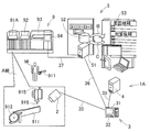
- FIG. 1 is a configuration diagram showing a device configuration of a substrate production status monitoring device 1 according to the first embodiment. As shown in the figure, the substrate production status monitoring device 1 is installed in a substrate production line 9.
- the board production line 9 includes a component mounter 91, a board appearance inspection machine 92, and a reflow machine 93 arranged in parallel on a common base 99 and connected by a board transfer device (not shown).
- a host computer 94 is disposed on the front side of the reflow machine 93.
- the configuration of the board production line 9 is not limited to the above, and may include a solder printer and a printing inspection machine, or a plurality of component mounting machines may be provided in parallel.
- the component mounter 91 has a component supply device, a component transfer device, and a component camera (not shown) in addition to the above-described substrate transfer device.
- the substrate transfer device carries in, positions and unloads the substrate along the transfer path.
- the component supply device is a feeder-type device, and is configured by arranging a plurality of component supply feeders 911 in parallel.
- a component supply reel 912 is rotatably mounted on the component supply feeder 911. On the component supply reel 912, a carrier tape holding a large number of components at regular intervals is wound, and the carrier tape is pulled out to sequentially supply the components.
- Part A of FIG. 1 is an enlarged part of the inside of the component mounter 91, and a single component supply feeder 911 is illustrated.
- the component supply feeder 911 is changed and changed together with the component supply reel 912 by the operation of the operator M. Further, only the component supply reel 912 may be replaced by the operation of the operator M. By exchanging the component supply feeder 911 or the component supply reel 912, the component lot of the components to be supplied is changed.
- the change of the component supply feeder 911 and the component supply reel 912 corresponds to the change event of the present invention.
- the component transfer device is a so-called XY robot type device that can move in two orthogonal axes.
- the component transfer apparatus has a mounting head 915 that is driven in two orthogonal axes by a two-axis drive mechanism.
- the mounting head 915 holds one or a plurality of mounting nozzles 916 so as to be movable up and down.
- the mounting nozzle 916 sucks a component from the component supply feeder 911 using negative pressure and mounts the component on the positioned substrate.
- the mounting head 915 and the mounting nozzle 916 are changed according to the type and size of the component to be mounted.
- the change of the mounting head 915 and the mounting nozzle 916 corresponds to the change event of the present invention.
- the component camera images the state when the mounting nozzle 916 of the component transfer device sucks the component.
- the component camera determines, based on the obtained imaging data, whether or not the component suction state of the mounting nozzle 916, in other words, whether or not the correct position of the component is sucked, and whether or not the posture of the component is appropriate. If the component suction state of the mounting nozzle 916 is defective, the component camera determines that the suction operation error has occurred and instructs the component to be discarded. Naturally, an operation error also occurs when the mounting nozzle 916 cannot absorb the component or when the component is dropped halfway. In addition, the component camera determines that a minor defect less than the suction work error is a decrease in suction accuracy. The decrease in the suction accuracy when the mounting nozzle 916 sucks the component corresponds to the error sign event of the present invention.
- the operation times of the substrate transfer device, the component supply device, and the component transfer device constituting the component mounter 91 are managed. Operators often inspect and care for these devices when a predetermined operating time has elapsed. Regardless of whether or not inspection and maintenance are performed, in the first embodiment, the passage of a predetermined operation time is treated as a change event.
- the board appearance inspection machine 92 is arranged on the rear process side of the component mounting machine 91 and inspects the appearance of the board. More specifically, the board appearance inspection machine 92 inspects whether or not each component is correctly and correctly mounted at a specified mounting position on the board. The board appearance inspection machine 92 determines that there is a mounting work error if the mounting position of the component is shifted more than the allowable error or the mounting posture is incorrect. Naturally, a work error is caused even if a component is not mounted. The board appearance inspection machine 92 determines that a minor defect less than the mounting operation error is a decrease in mounting accuracy. The reduction in mounting accuracy corresponds to the error sign event of the present invention.
- the reflow machine 93 is arranged on the subsequent process side of the board appearance inspection machine 92, and the board that has been judged acceptable by the board appearance inspection machine 92 is carried in.
- the reflow machine 93 heats and remelts the paste-like solder between the substrate base material and the component, and then cools and solidifies it to complete the soldering operation.
- the host computer 94 is connected to the component mounting machine 91, the board appearance inspection machine 92, and the reflow machine 93 by communication lines, and comprehensively manages the work progress of these devices 91 to 93.
- Information on work errors such as a change event that has occurred in the component mounting machine 91, an error indication event of a decrease in component suction accuracy, and a component suction work error is transmitted to the host computer 94.
- information about work error such as an error indication event of component mounting accuracy reduction occurring in the board appearance inspection machine 92 and a mounting work error is also transmitted to the host computer 94.
- the board production status monitoring apparatus 1 includes a camera unit 2, a moving image storage computer 3, and an external storage memory 4.
- the camera unit 2 is disposed inside the component mounter 91.
- the moving image storage computer 3 and the external storage memory 4 can be arranged beside the board production line 9 or in a monitoring room separated from the board production line 9, and there is no particular restriction on the arrangement.
- the camera unit 2 is incorporated in the component transfer device of the component mounter 91, and is moved together with the mounting head 915 by a two-axis drive mechanism.
- the camera unit 2 captures a moving image of the state of component suction and mounting by the mounting nozzle 916 and outputs moving image data.
- the present invention is not limited to the above, and only one implementation state of suction and mounting may be imaged, or two fixed cameras may share the suction and mounting.
- the moving image storage computer 3 includes general-purpose hardware and dedicated software for monitoring the production status of the substrate. Examples of hardware of the moving image storage computer 3 include a CPU, a storage device, a display 31, a keyboard 32, and the like (not shown), but are not limited thereto.
- the moving image storage computer 3 is connected to the camera unit 2 via a communication line 33.
- the moving image storage computer 3 controls the imaging operation of the camera unit 2 and receives moving image data obtained by the imaging operation from the camera unit 2.
- the storage device of the moving image storage computer 3 can temporarily store moving image data as a buffer memory. However, since the storage capacity of the buffer memory is limited, the temporarily stored moving image data is deleted in order from the oldest.
- the moving image storage computer 3 is connected to the host computer 94 of the board production line 9 through a communication line 34.
- the moving image storage computer 3 receives information on change events, error sign events, and work errors from the host computer 94. This information may be received by communication at regular time intervals, or by temporary interrupt processing.
- the external storage memory 4 is a storage device having a much larger storage capacity than the buffer memory of the moving image storage computer 3.
- the external storage memory 4 is connected to the moving image storage computer 3 via a communication line 35.
- the external storage memory 4 is controlled by the moving image storage computer 3 and can store and read the transmitted moving image data.
- the external storage memory 4 unlike the buffer memory of the moving image storage computer 3, there is no concern that the storage capacity is insufficient even if all transmitted moving image data is stored.
- the data operation unit, trigger event detection unit, imaging start unit, work error detection unit, data storage unit, error display unit, and imaging end unit of the present invention are realized by software of the video storage computer 3.
- the data operation unit receives the moving image data from the camera unit 2, stores the moving image data, and displays it.
- the actual state of the data operation unit is that the moving image storage computer 3 receives the moving image data from the camera unit 2, temporarily stores or stores it in the storage device, and displays it on the display 31.
- Specific storage destinations, storage methods, and display methods for moving image data are defined in detail by means described below.
- the trigger event detection unit triggers a change event in which an operation condition of the operation in which the mounting nozzle 916 sucks and mounts a component in the component mounter 91 changes, and an error sign event that indicates a sign that the suction and mounting operation becomes a work error. Detect as an event.
- the actual condition of the trigger event detection unit is that the moving image storage computer 3 receives information on a change event and an error sign event from the host computer 94.
- the board production line 9 shares a part of the function of the trigger event detection unit.
- the imaging start unit When the trigger event detection unit detects the trigger event, the imaging start unit causes the camera unit 2 to start moving image capturing, and causes the data operation unit to temporarily store the moving image data in units of a predetermined data length.
- the actual state of the imaging start means is that when the moving image storage computer 3 receives information on the change event and the error sign event from the host computer 94, the moving image data received from the camera unit 2 is sent to the camera unit 2. Temporarily storing the data in the buffer memory in units of a predetermined data length.
- the error detection unit detects work errors.
- the actual state of the error detection unit is that the moving image storage computer 3 receives information on an error event from the host computer 94.
- the board production line 9 shares part of the function of the error detection unit.
- the data storage unit When the work error detection unit detects a work error, the data storage unit causes the data operation unit to store moving image data in a predetermined data length unit when the work error is detected.
- the actual state of the data storage means is that when the moving image storage computer 3 receives information on the operation error from the host computer 94, the moving image data received from the camera unit 2 is stored in the external storage memory 4 in units of a predetermined data length.
- the error time display means when the work error detection unit detects a work error, causes the data operation unit to display moving image data of a predetermined data length unit at the time when the work error is detected.
- the actual state of the error display means is that when the moving image storage computer 3 receives the error event information from the host computer 94, the moving image data is read from the buffer memory or the external storage memory 4 and displayed on the display 31.
- Imaging end means after a predetermined time has elapsed since the trigger event detection unit detected the change event, and after the error sign event detected by the trigger event detection unit disappeared and returned to the normal operating range, The camera unit 2 ends the moving image capturing, and the data operation unit ends the temporary storage of the moving image data.
- the actual condition of the imaging end means is that the predetermined time is set in advance by the moving image storage computer 3 and no error event information is received even if the predetermined time elapses after receiving the change event information from the host computer 94. Is to issue a command to the camera unit 2 to end imaging.
- the actual state of the imaging end means is that when the moving image storage computer 3 receives the information of the error sign event from the host computer 94, the camera unit 2 continues the image capturing of the error sign event and the error sign event information is lost. Is to issue a command to the camera unit 2 to end the imaging.
- FIG. 2 is a flowchart showing an operation when a change event occurs in the device 1 of the first embodiment.
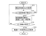
- FIG. 3 is a flowchart showing an operation when an error sign event occurs in the apparatus 1 of the first embodiment.
- the flowcharts of FIGS. 2 and 3 function throughout the operation of the substrate production line 9.
- step S1 the moving image storage computer 3 sequentially checks whether or not the information on the change event has been received from the host computer 94. If no change event information is received, step S1 is repeated. If change event information is received, the process proceeds to step S2. In step S2, the moving image storage computer 3 causes the camera unit 2 to start moving image capturing. Further, in the next step S3, the moving image storage computer 3 temporarily stores the moving image data obtained over a predetermined time in the buffer memory.
- step S4 the moving image storage computer 3 checks whether or not error event information has been received from the host computer 94. If no error event information has been received, the process returns to step S1, and if received, the process proceeds to step S5.
- step S5 the moving image storage computer 3 displays the moving image data for a predetermined time on the display 31, and transfers the moving image data for the predetermined time from the buffer memory to the external storage memory 4 for storage.
- step S11 of FIG. 3 the component mounter 91 performs the operation of sucking and mounting components.
- the host computer 94 knows whether or not there is an error sign event.
- step S ⁇ b> 12 the moving image storage computer 3 sequentially confirms whether or not error sign event information has been received from the host computer 94. If no error symptom event information is received, the process returns to step S11. If error symptom event information is received, the process proceeds to step S13.
- step S13 the moving image storage computer 3 causes the camera unit 2 to start moving image capturing, and temporarily stores the obtained moving image data in the buffer memory.
- step S14 the moving image storage computer 3 checks whether error event information is received from the host computer 94 or not. If no error event information has been received, the process returns to step S11, and if received, the process proceeds to step S15.
- step S15 the moving image storage computer 3 displays the moving image data on the display 31 and transfers the moving image data from the buffer memory to the external storage memory 4 for storage.
- FIG. 4 is a diagram conceptually illustrating the monitoring function of the board production status monitoring apparatus 1 according to the first embodiment.
- the horizontal axis indicates the number of times of mounting a specific part
- the vertical axis indicates the mounting accuracy of the specific part.
- the timing T indicates the timing T at which a change in the component supply feeder 911 that supplies a specific component, that is, a change event has occurred.
- an accuracy decrease determination value E1 for determining a mounting accuracy decrease and an error determination value E2 for determining a mounting error are shown.
- the mounting accuracy of the specific part is well stabilized after the timing T when the change event occurs, the importance of the moving image data for 10 times is low.
- the mounting accuracy of the specific component varies in an unstable manner, and there are cases where the accuracy degradation determination value E1 and the error determination value E2 are exceeded. Then, when the mounting accuracy of the specific component becomes a large error value E3 and exceeds the error determination value E2, it is determined as an error event. Accordingly, it is possible to shift the moving image data corresponding to the number of mounting operations 10 times before and after the occurrence of a highly important error event from temporary storage to long-term storage.
- the subsequent error events of the error values E4 and E5 the moving image data before and after the occurrence can be stored for a long time.
- the monitoring function described in FIG. 4 is an example when the component supply feeder 911 is changed, and another method can be adopted.
- the mounting head 915 or the mounting nozzle 916 it is preferable to monitor a decrease in suction accuracy and mounting accuracy or an error for all components without limiting to specific components.
- the camera unit 2 captures a work execution status as a moving image when a trigger event, that is, a change event and an error indication event, which is assumed to be likely to cause a work error, Keep video data temporarily. Furthermore, when the work error is detected, the moving image data at the time of the important work error is stored not for temporary storage but for a long period of time. Therefore, the operator can grasp in advance the risk that a work error will occur and take measures as necessary to prevent the work error. Also, when a work error actually occurs, the video data is automatically displayed, so you can check the work status before and after the work error, and also compare it with past work errors, so you can respond efficiently. It becomes possible.
- the camera unit 2 does not capture moving images at all times when no trigger event occurs. Therefore, the buffer memory for storing moving image data and the storage capacity of the external storage memory 4 can be reduced and used effectively. Thereby, the apparatus configuration and the apparatus operation can be simplified to reduce the apparatus cost, or the apparatus structure can be optimized to improve the cost performance.
- FIG. 5 is a configuration diagram showing a device configuration of the substrate production status monitoring device 1A of the second embodiment.
- an in-process quality management system 5 In Process Quality Control System, hereinafter abbreviated as IPQC system 5
- IPQC system 5 In Process Quality Control System
- the board production status monitoring apparatus 1A according to the second embodiment has all the functions of the apparatus 1 according to the first embodiment and the functions of the IPQC system 5.
- the IPQC system 5 is a system for improving the function of preventing work errors.
- the IPQC system 5 includes a database server 51, a database unit 52, and various input / output devices 53.
- the database server 51 is a computer that manages the database unit 52 and performs various calculations, analysis, inference, and the like.
- the database server 51 is connected to the moving image storage computer 3 and the host computer 94 via communication lines 36 and 37, and can exchange data with each other.
- the database server 51 may be connected to the moving image storage computer 3 via the external storage memory 4.
- the database server 51 acquires, in real time, all data representing the work implementation status from the host computer 94 in addition to information on change events, error sign events, and work errors. As examples of all the data, component adsorption accuracy and mounting accuracy can be exemplified.
- the database server 51 analyzes the stability of these data, and associates the relationship with the occurrence location of the change event when the stability decreases.
- the database unit 52 holds a factor candidate that is a candidate for a factor that causes an error sign event and a countermeasure candidate that is a candidate for a measure for eliminating the factor candidate. Accordingly, the database server 51 can infer the error symptom event cause candidate and the countermeasure candidate by searching the database unit 52.
- the inferred factor candidates and countermeasure candidates are output and displayed on the input / output device 53 and provided to the operator M, as indicated by the white arrow B in FIG. This corresponds to a part of the indication unit for indication of the present invention.
- the remainder of the sign display means of the present invention is realized by software of the moving image storage computer 3. That is, when the trigger event detecting unit detects an error sign event, the sign time display means displays moving image data in a predetermined data length unit at the time when the error sign event is detected on the data operation unit. As for the actual state of the sign display means, when the moving image storage computer 3 receives the information of the error symptom event from the host computer 94 via the database server 51, the moving image data is read from the buffer memory or the external storage memory 4 and displayed. Is to display.
- FIG. 6 is a diagram illustrating a case where a decrease in mounting accuracy, which is an example of an error sign event, occurs in the second embodiment.
- the operator M replaces the mounting nozzle 917 and sets it in the component mounting machine 91A, and a change event has occurred.
- the mounting nozzle 917 mounts the component P on the board K in the component mounting machine 91A
- the mounting position shifts from the ideal position R, and the mounting accuracy is reduced, that is, an error sign phenomenon occurs.
- the database server 51 associates the decrease in mounting accuracy with the replacement of the mounting nozzle 917, and also associates any other factor candidates. Further, the database server 51 infers all countermeasure candidates for all factor candidates. On the other hand, the moving image storage computer 3 reproduces and displays on the display 31 the image data of the work implementation status in which the component P is mounted.
- the operator M can check the factor candidate and the countermeasure candidate against the moving image data, and can confirm and implement a preferable countermeasure. Furthermore, the operator M can input the contents of countermeasures implemented using the input / output device 53, as indicated by the white arrow C in FIG. As a result, the database server 51 can analyze the relationship between the state of the subsequent change of the error sign event and the content of the implemented countermeasure, and output the effect of the countermeasure content to the input / output device 53 for display.
- the same effect as that of the first embodiment occurs, and the function of preventing work errors is improved.
- the operator M can collate the candidate factor and the countermeasure candidate with the moving image data and implement a preferable measure. This can be surely prevented before progressing to work errors.
- the change event, the error sign event, and the work error are not limited to the above contents, and may be other events.
- the camera unit 2 is incorporated in the component mounters 91 and 91A.
- the present invention is not limited to this.
- the camera unit 2 may be incorporated in a drawing type solder printer using an ink jet device or a dispenser device, and the implementation status of solder printing may be monitored.
- the present invention can be variously applied and modified.
Landscapes
- Engineering & Computer Science (AREA)
- Operations Research (AREA)
- Manufacturing & Machinery (AREA)
- Microelectronics & Electronic Packaging (AREA)
- Physics & Mathematics (AREA)
- General Physics & Mathematics (AREA)
- Automation & Control Theory (AREA)
- Multimedia (AREA)
- Signal Processing (AREA)
- Supply And Installment Of Electrical Components (AREA)
Abstract
Priority Applications (5)
| Application Number | Priority Date | Filing Date | Title |
|---|---|---|---|
| CN201280077015.7A CN104770081B (zh) | 2012-11-13 | 2012-11-13 | 基板生产状况监视装置 |
| US14/441,694 US10012970B2 (en) | 2012-11-13 | 2012-11-13 | Board production state monitoring system |
| EP12888232.1A EP2922380B1 (fr) | 2012-11-13 | 2012-11-13 | Dispositif de surveillance d'état de production de substrat |
| JP2014546754A JP6243346B2 (ja) | 2012-11-13 | 2012-11-13 | 基板生産状況監視装置 |
| PCT/JP2012/079367 WO2014076755A1 (fr) | 2012-11-13 | 2012-11-13 | Dispositif de surveillance d'état de production de substrat |
Applications Claiming Priority (1)
| Application Number | Priority Date | Filing Date | Title |
|---|---|---|---|
| PCT/JP2012/079367 WO2014076755A1 (fr) | 2012-11-13 | 2012-11-13 | Dispositif de surveillance d'état de production de substrat |
Publications (1)
| Publication Number | Publication Date |
|---|---|
| WO2014076755A1 true WO2014076755A1 (fr) | 2014-05-22 |
Family
ID=50730703
Family Applications (1)
| Application Number | Title | Priority Date | Filing Date |
|---|---|---|---|
| PCT/JP2012/079367 WO2014076755A1 (fr) | 2012-11-13 | 2012-11-13 | Dispositif de surveillance d'état de production de substrat |
Country Status (5)
| Country | Link |
|---|---|
| US (1) | US10012970B2 (fr) |
| EP (1) | EP2922380B1 (fr) |
| JP (1) | JP6243346B2 (fr) |
| CN (1) | CN104770081B (fr) |
| WO (1) | WO2014076755A1 (fr) |
Cited By (10)
| Publication number | Priority date | Publication date | Assignee | Title |
|---|---|---|---|---|
| JP2014082530A (ja) * | 2014-02-14 | 2014-05-08 | Nec Corp | 設備監視システム、設備監視方法および設備監視プログラム |
| JP2018113610A (ja) * | 2017-01-12 | 2018-07-19 | ファナック株式会社 | 視覚センサの異常原因推定システム |
| WO2019021361A1 (fr) * | 2017-07-25 | 2019-01-31 | 株式会社Fuji | Système de gestion de traitement de substrat |
| JP2019129220A (ja) * | 2018-01-24 | 2019-08-01 | ヤマハ発動機株式会社 | 部品実装システム |
| WO2020095399A1 (fr) * | 2018-11-08 | 2020-05-14 | ヤマハ発動機株式会社 | Dispositif de montage de composant |
| JP2021012937A (ja) * | 2019-07-05 | 2021-02-04 | パナソニックIpマネジメント株式会社 | リモート操作システム |
| JP2021082757A (ja) * | 2019-11-21 | 2021-05-27 | 株式会社Fuji | 部品装着システム |
| WO2022003772A1 (fr) * | 2020-06-29 | 2022-01-06 | 株式会社Fuji | Système de montage de composants |
| WO2022269679A1 (fr) * | 2021-06-21 | 2022-12-29 | 株式会社Fuji | Procédé de contrôle pour système de montage de composant et système de montage de composant |
| WO2024075202A1 (fr) * | 2022-10-05 | 2024-04-11 | 株式会社Fuji | Dispositif d'aide à la production et procédé d'aide à la production |
Families Citing this family (20)
| Publication number | Priority date | Publication date | Assignee | Title |
|---|---|---|---|---|
| EP3047715B1 (fr) * | 2013-09-18 | 2019-03-27 | Mycronic AB | Procédé, système et dispositif pour identifier un bac dans un système smt |
| JP6689301B2 (ja) * | 2016-02-18 | 2020-04-28 | 株式会社Fuji | 部品判定装置および部品判定方法 |
| EP3493008B1 (fr) * | 2016-07-27 | 2021-08-25 | Fuji Corporation | Dispositif de gestion de production de substrat et procédé de gestion de production de substrat |
| WO2018055754A1 (fr) * | 2016-09-26 | 2018-03-29 | 富士機械製造株式会社 | Système permettant de surveiller une zone de travail extérieure d'une machine de montage de composants |
| JP6617291B2 (ja) * | 2016-10-25 | 2019-12-11 | パナソニックIpマネジメント株式会社 | 部品実装システムおよび段取り作業の進捗表示システム |
| JP6732038B2 (ja) * | 2016-11-09 | 2020-07-29 | 株式会社Fuji | 部品実装ラインの生産管理システム及び生産管理方法 |
| CN110024511B (zh) * | 2016-12-01 | 2020-10-30 | 株式会社富士 | 元件安装生产线的生产管理系统 |
| US11259451B2 (en) | 2017-02-02 | 2022-02-22 | Fuji Corporation | Production management device |
| EP3606316B1 (fr) * | 2017-03-30 | 2024-04-24 | Fuji Corporation | Dispositif de gestion de maintenance |
| WO2020017027A1 (fr) * | 2018-07-20 | 2020-01-23 | 株式会社Fuji | Dispositif de stockage de données d'image et procédé de stockage de données d'image |
| JP7193540B2 (ja) * | 2018-08-23 | 2022-12-20 | 株式会社Fuji | 移動作業管理装置、実装システム及び移動作業管理方法 |
| DE102018133183B4 (de) * | 2018-12-20 | 2020-07-09 | Asm Assembly Systems Gmbh & Co. Kg | Verfahren zur Steuerung eines Bestückprozesses von Bestückautomaten, Elektronische Steuerung von Bestückautomaten, Bestückautomat und System zur Steuerung einer Fertigungslinie in der Leiterplattenfertigung |
| US10481579B1 (en) * | 2019-02-28 | 2019-11-19 | Nanotronics Imaging, Inc. | Dynamic training for assembly lines |
| EP4037448A4 (fr) * | 2019-09-27 | 2022-10-19 | Fuji Corporation | Dispositif de simulation et procédé de simulation |
| US11100221B2 (en) | 2019-10-08 | 2021-08-24 | Nanotronics Imaging, Inc. | Dynamic monitoring and securing of factory processes, equipment and automated systems |
| US11086988B1 (en) | 2020-02-28 | 2021-08-10 | Nanotronics Imaging, Inc. | Method, systems and apparatus for intelligently emulating factory control systems and simulating response data |
| JP2022076222A (ja) * | 2020-11-09 | 2022-05-19 | 株式会社Fuji | 異常予測装置、送出装置及び異常予測方法 |
| CN112904446B (zh) * | 2021-03-03 | 2023-11-10 | 格力电器(合肥)有限公司 | 管件检测方法、装置、系统、电子设备和存储介质 |
| CN117413230A (zh) | 2021-07-13 | 2024-01-16 | 株式会社富士 | 工序管理装置 |
| CN113589756B (zh) * | 2021-10-08 | 2021-12-14 | 华兴源创(成都)科技有限公司 | 位移传感信号触发装置、设备、检测系统及相关方法 |
Citations (4)
| Publication number | Priority date | Publication date | Assignee | Title |
|---|---|---|---|---|
| JP2002111299A (ja) | 2000-09-29 | 2002-04-12 | Matsushita Electric Ind Co Ltd | 部品装着方法及び装置 |
| JP2008085559A (ja) * | 2006-09-27 | 2008-04-10 | Omron Corp | 外観検査用の画像の保存方法および画像保存処理装置 |
| JP2008098441A (ja) | 2006-10-12 | 2008-04-24 | Oht Inc | 基板搬送機構 |
| JP2011077095A (ja) * | 2009-09-29 | 2011-04-14 | Nec Corp | 設備監視システム、設備監視方法および設備監視プログラム |
Family Cites Families (11)
| Publication number | Priority date | Publication date | Assignee | Title |
|---|---|---|---|---|
| US6546308B2 (en) * | 1993-12-28 | 2003-04-08 | Hitachi, Ltd, | Method and system for manufacturing semiconductor devices, and method and system for inspecting semiconductor devices |
| JP3508272B2 (ja) * | 1995-03-03 | 2004-03-22 | 松下電器産業株式会社 | 部品装着方法 |
| US6542830B1 (en) * | 1996-03-19 | 2003-04-01 | Hitachi, Ltd. | Process control system |
| JP2004200224A (ja) * | 2002-12-16 | 2004-07-15 | Yamagata Casio Co Ltd | 認識不良解決方法及びそれを用いた電子部品搭載装置 |
| JP2006013120A (ja) * | 2004-06-25 | 2006-01-12 | Matsushita Electric Ind Co Ltd | 不具合原因究明システム |
| JP2008149407A (ja) * | 2006-12-18 | 2008-07-03 | Mitsubishi Heavy Ind Ltd | 製造設備 |
| US8473100B2 (en) * | 2008-04-25 | 2013-06-25 | Fanuc Robotics America, Inc. | System and method for dynamically switching conveyors for robots |
| JP2010010463A (ja) * | 2008-06-27 | 2010-01-14 | Juki Corp | 電子部品実装装置 |
| JP5385010B2 (ja) * | 2009-05-29 | 2014-01-08 | Juki株式会社 | 電子部品実装装置 |
| JP5737989B2 (ja) * | 2011-02-14 | 2015-06-17 | 富士機械製造株式会社 | 部品実装機 |
| JP5798371B2 (ja) * | 2011-05-09 | 2015-10-21 | 富士機械製造株式会社 | 基準マークモデルテンプレート作成方法 |
-
2012
- 2012-11-13 JP JP2014546754A patent/JP6243346B2/ja active Active
- 2012-11-13 WO PCT/JP2012/079367 patent/WO2014076755A1/fr active Application Filing
- 2012-11-13 US US14/441,694 patent/US10012970B2/en active Active
- 2012-11-13 CN CN201280077015.7A patent/CN104770081B/zh active Active
- 2012-11-13 EP EP12888232.1A patent/EP2922380B1/fr active Active
Patent Citations (4)
| Publication number | Priority date | Publication date | Assignee | Title |
|---|---|---|---|---|
| JP2002111299A (ja) | 2000-09-29 | 2002-04-12 | Matsushita Electric Ind Co Ltd | 部品装着方法及び装置 |
| JP2008085559A (ja) * | 2006-09-27 | 2008-04-10 | Omron Corp | 外観検査用の画像の保存方法および画像保存処理装置 |
| JP2008098441A (ja) | 2006-10-12 | 2008-04-24 | Oht Inc | 基板搬送機構 |
| JP2011077095A (ja) * | 2009-09-29 | 2011-04-14 | Nec Corp | 設備監視システム、設備監視方法および設備監視プログラム |
Cited By (17)
| Publication number | Priority date | Publication date | Assignee | Title |
|---|---|---|---|---|
| JP2014082530A (ja) * | 2014-02-14 | 2014-05-08 | Nec Corp | 設備監視システム、設備監視方法および設備監視プログラム |
| JP2018113610A (ja) * | 2017-01-12 | 2018-07-19 | ファナック株式会社 | 視覚センサの異常原因推定システム |
| US10497146B2 (en) | 2017-01-12 | 2019-12-03 | Fanuc Corporation | Visual sensor abnormality cause estimation system |
| WO2019021361A1 (fr) * | 2017-07-25 | 2019-01-31 | 株式会社Fuji | Système de gestion de traitement de substrat |
| JPWO2019021361A1 (ja) * | 2017-07-25 | 2020-03-19 | 株式会社Fuji | 対基板作業管理システム |
| JP7067938B2 (ja) | 2018-01-24 | 2022-05-16 | ヤマハ発動機株式会社 | 部品実装システム |
| JP2019129220A (ja) * | 2018-01-24 | 2019-08-01 | ヤマハ発動機株式会社 | 部品実装システム |
| JP7121138B2 (ja) | 2018-11-08 | 2022-08-17 | ヤマハ発動機株式会社 | 部品実装装置 |
| JPWO2020095399A1 (ja) * | 2018-11-08 | 2021-09-02 | ヤマハ発動機株式会社 | 部品実装装置 |
| WO2020095399A1 (fr) * | 2018-11-08 | 2020-05-14 | ヤマハ発動機株式会社 | Dispositif de montage de composant |
| JP2021012937A (ja) * | 2019-07-05 | 2021-02-04 | パナソニックIpマネジメント株式会社 | リモート操作システム |
| JP7285396B2 (ja) | 2019-07-05 | 2023-06-02 | パナソニックIpマネジメント株式会社 | リモート操作システム |
| JP2021082757A (ja) * | 2019-11-21 | 2021-05-27 | 株式会社Fuji | 部品装着システム |
| JP7330075B2 (ja) | 2019-11-21 | 2023-08-21 | 株式会社Fuji | 部品装着システム |
| WO2022003772A1 (fr) * | 2020-06-29 | 2022-01-06 | 株式会社Fuji | Système de montage de composants |
| WO2022269679A1 (fr) * | 2021-06-21 | 2022-12-29 | 株式会社Fuji | Procédé de contrôle pour système de montage de composant et système de montage de composant |
| WO2024075202A1 (fr) * | 2022-10-05 | 2024-04-11 | 株式会社Fuji | Dispositif d'aide à la production et procédé d'aide à la production |
Also Published As
| Publication number | Publication date |
|---|---|
| JP6243346B2 (ja) | 2017-12-06 |
| EP2922380A1 (fr) | 2015-09-23 |
| JPWO2014076755A1 (ja) | 2016-09-08 |
| CN104770081A (zh) | 2015-07-08 |
| US10012970B2 (en) | 2018-07-03 |
| EP2922380B1 (fr) | 2019-03-27 |
| US20150286202A1 (en) | 2015-10-08 |
| CN104770081B (zh) | 2018-04-13 |
| EP2922380A4 (fr) | 2016-04-20 |
Similar Documents
| Publication | Publication Date | Title |
|---|---|---|
| JP6243346B2 (ja) | 基板生産状況監視装置 | |
| JP4767995B2 (ja) | 部品実装方法、部品実装機、実装条件決定方法、実装条件決定装置およびプログラム | |
| WO2012111202A1 (fr) | Machine de montage d'élément | |
| KR101647653B1 (ko) | 부품 공급 장치 및 표면 실장기 | |
| JP2008218706A (ja) | 部品移載装置、表面実装機、及び電子部品検査装置 | |
| JP5214478B2 (ja) | 電子部品装着方法及び電子部品装着装置 | |
| JP4995745B2 (ja) | 部品実装装置 | |
| WO2017216950A1 (fr) | Dispositif de montage de composants et système de montage de composants | |
| JP5980944B2 (ja) | 部品実装ラインの生産監視システム及び生産監視方法 | |
| WO2016046932A1 (fr) | Dispositif de montage et procédé de montage | |
| JP5100684B2 (ja) | 電子部品装着装置の管理システムにおける管理方法 | |
| JP6975327B2 (ja) | 部品実装ライン | |
| JP2009123902A (ja) | 部品実装条件決定方法、部品実装条件決定装置及びプログラム | |
| JP2024111259A (ja) | 管理装置および作業指令決定方法 | |
| JP6270841B2 (ja) | 検査制御装置、実装システム及び検査制御方法 | |
| JP5713441B2 (ja) | 部品実装システム | |
| WO2019163044A1 (fr) | Système de montage de composants | |
| JP4922460B2 (ja) | 電子部品装着装置 | |
| JP7197705B2 (ja) | 実装装置、実装システム及び検査実装方法 | |
| WO2022003772A1 (fr) | Système de montage de composants | |
| JP7495245B2 (ja) | 管理装置 | |
| JP2006228799A (ja) | 検査結果報知装置 | |
| WO2023139789A1 (fr) | Dispositif de préparation, dispositif de montage, système de montage et procédé de traitement d'informations | |
| WO2023012981A1 (fr) | Système de montage de composants | |
| JP7121138B2 (ja) | 部品実装装置 |
Legal Events
| Date | Code | Title | Description |
|---|---|---|---|
| 121 | Ep: the epo has been informed by wipo that ep was designated in this application |
Ref document number: 12888232 Country of ref document: EP Kind code of ref document: A1 |
|
| ENP | Entry into the national phase |
Ref document number: 2014546754 Country of ref document: JP Kind code of ref document: A |
|
| WWE | Wipo information: entry into national phase |
Ref document number: 14441694 Country of ref document: US |
|
| NENP | Non-entry into the national phase |
Ref country code: DE |
|
| WWE | Wipo information: entry into national phase |
Ref document number: 2012888232 Country of ref document: EP |