WO2014073408A1 - Dispositif de purification de gaz d'échappement pour un moteur à combustion interne - Google Patents
Dispositif de purification de gaz d'échappement pour un moteur à combustion interne Download PDFInfo
- Publication number
- WO2014073408A1 WO2014073408A1 PCT/JP2013/079137 JP2013079137W WO2014073408A1 WO 2014073408 A1 WO2014073408 A1 WO 2014073408A1 JP 2013079137 W JP2013079137 W JP 2013079137W WO 2014073408 A1 WO2014073408 A1 WO 2014073408A1
- Authority
- WO
- WIPO (PCT)
- Prior art keywords
- amount
- catalyst
- temperature
- nox
- scr catalyst
- Prior art date
Links
Images


Classifications
-
- F—MECHANICAL ENGINEERING; LIGHTING; HEATING; WEAPONS; BLASTING
- F01—MACHINES OR ENGINES IN GENERAL; ENGINE PLANTS IN GENERAL; STEAM ENGINES
- F01N—GAS-FLOW SILENCERS OR EXHAUST APPARATUS FOR MACHINES OR ENGINES IN GENERAL; GAS-FLOW SILENCERS OR EXHAUST APPARATUS FOR INTERNAL COMBUSTION ENGINES
- F01N3/00—Exhaust or silencing apparatus having means for purifying, rendering innocuous, or otherwise treating exhaust
- F01N3/08—Exhaust or silencing apparatus having means for purifying, rendering innocuous, or otherwise treating exhaust for rendering innocuous
- F01N3/10—Exhaust or silencing apparatus having means for purifying, rendering innocuous, or otherwise treating exhaust for rendering innocuous by thermal or catalytic conversion of noxious components of exhaust
- F01N3/105—General auxiliary catalysts, e.g. upstream or downstream of the main catalyst
- F01N3/106—Auxiliary oxidation catalysts
-
- B—PERFORMING OPERATIONS; TRANSPORTING
- B01—PHYSICAL OR CHEMICAL PROCESSES OR APPARATUS IN GENERAL
- B01D—SEPARATION
- B01D53/00—Separation of gases or vapours; Recovering vapours of volatile solvents from gases; Chemical or biological purification of waste gases, e.g. engine exhaust gases, smoke, fumes, flue gases, aerosols
- B01D53/34—Chemical or biological purification of waste gases
- B01D53/92—Chemical or biological purification of waste gases of engine exhaust gases
- B01D53/94—Chemical or biological purification of waste gases of engine exhaust gases by catalytic processes
- B01D53/9404—Removing only nitrogen compounds
- B01D53/9409—Nitrogen oxides
- B01D53/9431—Processes characterised by a specific device
-
- B—PERFORMING OPERATIONS; TRANSPORTING
- B01—PHYSICAL OR CHEMICAL PROCESSES OR APPARATUS IN GENERAL
- B01D—SEPARATION
- B01D53/00—Separation of gases or vapours; Recovering vapours of volatile solvents from gases; Chemical or biological purification of waste gases, e.g. engine exhaust gases, smoke, fumes, flue gases, aerosols
- B01D53/34—Chemical or biological purification of waste gases
- B01D53/92—Chemical or biological purification of waste gases of engine exhaust gases
- B01D53/94—Chemical or biological purification of waste gases of engine exhaust gases by catalytic processes
- B01D53/9459—Removing one or more of nitrogen oxides, carbon monoxide, or hydrocarbons by multiple successive catalytic functions; systems with more than one different function, e.g. zone coated catalysts
- B01D53/9477—Removing one or more of nitrogen oxides, carbon monoxide, or hydrocarbons by multiple successive catalytic functions; systems with more than one different function, e.g. zone coated catalysts with catalysts positioned on separate bricks, e.g. exhaust systems
-
- B—PERFORMING OPERATIONS; TRANSPORTING
- B01—PHYSICAL OR CHEMICAL PROCESSES OR APPARATUS IN GENERAL
- B01D—SEPARATION
- B01D53/00—Separation of gases or vapours; Recovering vapours of volatile solvents from gases; Chemical or biological purification of waste gases, e.g. engine exhaust gases, smoke, fumes, flue gases, aerosols
- B01D53/34—Chemical or biological purification of waste gases
- B01D53/92—Chemical or biological purification of waste gases of engine exhaust gases
- B01D53/94—Chemical or biological purification of waste gases of engine exhaust gases by catalytic processes
- B01D53/9495—Controlling the catalytic process
-
- F—MECHANICAL ENGINEERING; LIGHTING; HEATING; WEAPONS; BLASTING
- F01—MACHINES OR ENGINES IN GENERAL; ENGINE PLANTS IN GENERAL; STEAM ENGINES
- F01N—GAS-FLOW SILENCERS OR EXHAUST APPARATUS FOR MACHINES OR ENGINES IN GENERAL; GAS-FLOW SILENCERS OR EXHAUST APPARATUS FOR INTERNAL COMBUSTION ENGINES
- F01N3/00—Exhaust or silencing apparatus having means for purifying, rendering innocuous, or otherwise treating exhaust
- F01N3/02—Exhaust or silencing apparatus having means for purifying, rendering innocuous, or otherwise treating exhaust for cooling, or for removing solid constituents of, exhaust
- F01N3/0205—Exhaust or silencing apparatus having means for purifying, rendering innocuous, or otherwise treating exhaust for cooling, or for removing solid constituents of, exhaust using heat exchangers
-
- F—MECHANICAL ENGINEERING; LIGHTING; HEATING; WEAPONS; BLASTING
- F01—MACHINES OR ENGINES IN GENERAL; ENGINE PLANTS IN GENERAL; STEAM ENGINES
- F01N—GAS-FLOW SILENCERS OR EXHAUST APPARATUS FOR MACHINES OR ENGINES IN GENERAL; GAS-FLOW SILENCERS OR EXHAUST APPARATUS FOR INTERNAL COMBUSTION ENGINES
- F01N3/00—Exhaust or silencing apparatus having means for purifying, rendering innocuous, or otherwise treating exhaust
- F01N3/08—Exhaust or silencing apparatus having means for purifying, rendering innocuous, or otherwise treating exhaust for rendering innocuous
- F01N3/0807—Exhaust or silencing apparatus having means for purifying, rendering innocuous, or otherwise treating exhaust for rendering innocuous by using absorbents or adsorbents
- F01N3/0814—Exhaust or silencing apparatus having means for purifying, rendering innocuous, or otherwise treating exhaust for rendering innocuous by using absorbents or adsorbents combined with catalytic converters, e.g. NOx absorption/storage reduction catalysts
-
- F—MECHANICAL ENGINEERING; LIGHTING; HEATING; WEAPONS; BLASTING
- F01—MACHINES OR ENGINES IN GENERAL; ENGINE PLANTS IN GENERAL; STEAM ENGINES
- F01N—GAS-FLOW SILENCERS OR EXHAUST APPARATUS FOR MACHINES OR ENGINES IN GENERAL; GAS-FLOW SILENCERS OR EXHAUST APPARATUS FOR INTERNAL COMBUSTION ENGINES
- F01N3/00—Exhaust or silencing apparatus having means for purifying, rendering innocuous, or otherwise treating exhaust
- F01N3/08—Exhaust or silencing apparatus having means for purifying, rendering innocuous, or otherwise treating exhaust for rendering innocuous
- F01N3/10—Exhaust or silencing apparatus having means for purifying, rendering innocuous, or otherwise treating exhaust for rendering innocuous by thermal or catalytic conversion of noxious components of exhaust
- F01N3/103—Oxidation catalysts for HC and CO only
-
- F—MECHANICAL ENGINEERING; LIGHTING; HEATING; WEAPONS; BLASTING
- F01—MACHINES OR ENGINES IN GENERAL; ENGINE PLANTS IN GENERAL; STEAM ENGINES
- F01N—GAS-FLOW SILENCERS OR EXHAUST APPARATUS FOR MACHINES OR ENGINES IN GENERAL; GAS-FLOW SILENCERS OR EXHAUST APPARATUS FOR INTERNAL COMBUSTION ENGINES
- F01N3/00—Exhaust or silencing apparatus having means for purifying, rendering innocuous, or otherwise treating exhaust
- F01N3/08—Exhaust or silencing apparatus having means for purifying, rendering innocuous, or otherwise treating exhaust for rendering innocuous
- F01N3/10—Exhaust or silencing apparatus having means for purifying, rendering innocuous, or otherwise treating exhaust for rendering innocuous by thermal or catalytic conversion of noxious components of exhaust
- F01N3/18—Exhaust or silencing apparatus having means for purifying, rendering innocuous, or otherwise treating exhaust for rendering innocuous by thermal or catalytic conversion of noxious components of exhaust characterised by methods of operation; Control
- F01N3/20—Exhaust or silencing apparatus having means for purifying, rendering innocuous, or otherwise treating exhaust for rendering innocuous by thermal or catalytic conversion of noxious components of exhaust characterised by methods of operation; Control specially adapted for catalytic conversion ; Methods of operation or control of catalytic converters
- F01N3/2006—Periodically heating or cooling catalytic reactors, e.g. at cold starting or overheating
-
- F—MECHANICAL ENGINEERING; LIGHTING; HEATING; WEAPONS; BLASTING
- F01—MACHINES OR ENGINES IN GENERAL; ENGINE PLANTS IN GENERAL; STEAM ENGINES
- F01N—GAS-FLOW SILENCERS OR EXHAUST APPARATUS FOR MACHINES OR ENGINES IN GENERAL; GAS-FLOW SILENCERS OR EXHAUST APPARATUS FOR INTERNAL COMBUSTION ENGINES
- F01N3/00—Exhaust or silencing apparatus having means for purifying, rendering innocuous, or otherwise treating exhaust
- F01N3/08—Exhaust or silencing apparatus having means for purifying, rendering innocuous, or otherwise treating exhaust for rendering innocuous
- F01N3/10—Exhaust or silencing apparatus having means for purifying, rendering innocuous, or otherwise treating exhaust for rendering innocuous by thermal or catalytic conversion of noxious components of exhaust
- F01N3/18—Exhaust or silencing apparatus having means for purifying, rendering innocuous, or otherwise treating exhaust for rendering innocuous by thermal or catalytic conversion of noxious components of exhaust characterised by methods of operation; Control
- F01N3/20—Exhaust or silencing apparatus having means for purifying, rendering innocuous, or otherwise treating exhaust for rendering innocuous by thermal or catalytic conversion of noxious components of exhaust characterised by methods of operation; Control specially adapted for catalytic conversion ; Methods of operation or control of catalytic converters
- F01N3/206—Adding periodically or continuously substances to exhaust gases for promoting purification, e.g. catalytic material in liquid form, NOx reducing agents
-
- F—MECHANICAL ENGINEERING; LIGHTING; HEATING; WEAPONS; BLASTING
- F01—MACHINES OR ENGINES IN GENERAL; ENGINE PLANTS IN GENERAL; STEAM ENGINES
- F01N—GAS-FLOW SILENCERS OR EXHAUST APPARATUS FOR MACHINES OR ENGINES IN GENERAL; GAS-FLOW SILENCERS OR EXHAUST APPARATUS FOR INTERNAL COMBUSTION ENGINES
- F01N3/00—Exhaust or silencing apparatus having means for purifying, rendering innocuous, or otherwise treating exhaust
- F01N3/08—Exhaust or silencing apparatus having means for purifying, rendering innocuous, or otherwise treating exhaust for rendering innocuous
- F01N3/10—Exhaust or silencing apparatus having means for purifying, rendering innocuous, or otherwise treating exhaust for rendering innocuous by thermal or catalytic conversion of noxious components of exhaust
- F01N3/18—Exhaust or silencing apparatus having means for purifying, rendering innocuous, or otherwise treating exhaust for rendering innocuous by thermal or catalytic conversion of noxious components of exhaust characterised by methods of operation; Control
- F01N3/20—Exhaust or silencing apparatus having means for purifying, rendering innocuous, or otherwise treating exhaust for rendering innocuous by thermal or catalytic conversion of noxious components of exhaust characterised by methods of operation; Control specially adapted for catalytic conversion ; Methods of operation or control of catalytic converters
- F01N3/2066—Selective catalytic reduction [SCR]
- F01N3/208—Control of selective catalytic reduction [SCR], e.g. dosing of reducing agent
-
- F—MECHANICAL ENGINEERING; LIGHTING; HEATING; WEAPONS; BLASTING
- F01—MACHINES OR ENGINES IN GENERAL; ENGINE PLANTS IN GENERAL; STEAM ENGINES
- F01N—GAS-FLOW SILENCERS OR EXHAUST APPARATUS FOR MACHINES OR ENGINES IN GENERAL; GAS-FLOW SILENCERS OR EXHAUST APPARATUS FOR INTERNAL COMBUSTION ENGINES
- F01N9/00—Electrical control of exhaust gas treating apparatus
- F01N9/005—Electrical control of exhaust gas treating apparatus using models instead of sensors to determine operating characteristics of exhaust systems, e.g. calculating catalyst temperature instead of measuring it directly
-
- B—PERFORMING OPERATIONS; TRANSPORTING
- B01—PHYSICAL OR CHEMICAL PROCESSES OR APPARATUS IN GENERAL
- B01D—SEPARATION
- B01D2251/00—Reactants
- B01D2251/20—Reductants
- B01D2251/206—Ammonium compounds
- B01D2251/2062—Ammonia
-
- B—PERFORMING OPERATIONS; TRANSPORTING
- B01—PHYSICAL OR CHEMICAL PROCESSES OR APPARATUS IN GENERAL
- B01D—SEPARATION
- B01D2251/00—Reactants
- B01D2251/20—Reductants
- B01D2251/206—Ammonium compounds
- B01D2251/2067—Urea
-
- F—MECHANICAL ENGINEERING; LIGHTING; HEATING; WEAPONS; BLASTING
- F01—MACHINES OR ENGINES IN GENERAL; ENGINE PLANTS IN GENERAL; STEAM ENGINES
- F01N—GAS-FLOW SILENCERS OR EXHAUST APPARATUS FOR MACHINES OR ENGINES IN GENERAL; GAS-FLOW SILENCERS OR EXHAUST APPARATUS FOR INTERNAL COMBUSTION ENGINES
- F01N2240/00—Combination or association of two or more different exhaust treating devices, or of at least one such device with an auxiliary device, not covered by indexing codes F01N2230/00 or F01N2250/00, one of the devices being
- F01N2240/16—Combination or association of two or more different exhaust treating devices, or of at least one such device with an auxiliary device, not covered by indexing codes F01N2230/00 or F01N2250/00, one of the devices being an electric heater, i.e. a resistance heater
-
- F—MECHANICAL ENGINEERING; LIGHTING; HEATING; WEAPONS; BLASTING
- F01—MACHINES OR ENGINES IN GENERAL; ENGINE PLANTS IN GENERAL; STEAM ENGINES
- F01N—GAS-FLOW SILENCERS OR EXHAUST APPARATUS FOR MACHINES OR ENGINES IN GENERAL; GAS-FLOW SILENCERS OR EXHAUST APPARATUS FOR INTERNAL COMBUSTION ENGINES
- F01N2430/00—Influencing exhaust purification, e.g. starting of catalytic reaction, filter regeneration, or the like, by controlling engine operating characteristics
- F01N2430/06—Influencing exhaust purification, e.g. starting of catalytic reaction, filter regeneration, or the like, by controlling engine operating characteristics by varying fuel-air ratio, e.g. by enriching fuel-air mixture
-
- F—MECHANICAL ENGINEERING; LIGHTING; HEATING; WEAPONS; BLASTING
- F01—MACHINES OR ENGINES IN GENERAL; ENGINE PLANTS IN GENERAL; STEAM ENGINES
- F01N—GAS-FLOW SILENCERS OR EXHAUST APPARATUS FOR MACHINES OR ENGINES IN GENERAL; GAS-FLOW SILENCERS OR EXHAUST APPARATUS FOR INTERNAL COMBUSTION ENGINES
- F01N2550/00—Monitoring or diagnosing the deterioration of exhaust systems
- F01N2550/22—Monitoring or diagnosing the deterioration of exhaust systems of electric heaters for exhaust systems or their power supply
-
- F—MECHANICAL ENGINEERING; LIGHTING; HEATING; WEAPONS; BLASTING
- F01—MACHINES OR ENGINES IN GENERAL; ENGINE PLANTS IN GENERAL; STEAM ENGINES
- F01N—GAS-FLOW SILENCERS OR EXHAUST APPARATUS FOR MACHINES OR ENGINES IN GENERAL; GAS-FLOW SILENCERS OR EXHAUST APPARATUS FOR INTERNAL COMBUSTION ENGINES
- F01N2560/00—Exhaust systems with means for detecting or measuring exhaust gas components or characteristics
- F01N2560/02—Exhaust systems with means for detecting or measuring exhaust gas components or characteristics the means being an exhaust gas sensor
- F01N2560/026—Exhaust systems with means for detecting or measuring exhaust gas components or characteristics the means being an exhaust gas sensor for measuring or detecting NOx
-
- F—MECHANICAL ENGINEERING; LIGHTING; HEATING; WEAPONS; BLASTING
- F01—MACHINES OR ENGINES IN GENERAL; ENGINE PLANTS IN GENERAL; STEAM ENGINES
- F01N—GAS-FLOW SILENCERS OR EXHAUST APPARATUS FOR MACHINES OR ENGINES IN GENERAL; GAS-FLOW SILENCERS OR EXHAUST APPARATUS FOR INTERNAL COMBUSTION ENGINES
- F01N2560/00—Exhaust systems with means for detecting or measuring exhaust gas components or characteristics
- F01N2560/06—Exhaust systems with means for detecting or measuring exhaust gas components or characteristics the means being a temperature sensor
-
- F—MECHANICAL ENGINEERING; LIGHTING; HEATING; WEAPONS; BLASTING
- F01—MACHINES OR ENGINES IN GENERAL; ENGINE PLANTS IN GENERAL; STEAM ENGINES
- F01N—GAS-FLOW SILENCERS OR EXHAUST APPARATUS FOR MACHINES OR ENGINES IN GENERAL; GAS-FLOW SILENCERS OR EXHAUST APPARATUS FOR INTERNAL COMBUSTION ENGINES
- F01N2560/00—Exhaust systems with means for detecting or measuring exhaust gas components or characteristics
- F01N2560/14—Exhaust systems with means for detecting or measuring exhaust gas components or characteristics having more than one sensor of one kind
-
- F—MECHANICAL ENGINEERING; LIGHTING; HEATING; WEAPONS; BLASTING
- F01—MACHINES OR ENGINES IN GENERAL; ENGINE PLANTS IN GENERAL; STEAM ENGINES
- F01N—GAS-FLOW SILENCERS OR EXHAUST APPARATUS FOR MACHINES OR ENGINES IN GENERAL; GAS-FLOW SILENCERS OR EXHAUST APPARATUS FOR INTERNAL COMBUSTION ENGINES
- F01N2570/00—Exhaust treating apparatus eliminating, absorbing or adsorbing specific elements or compounds
- F01N2570/14—Nitrogen oxides
-
- F—MECHANICAL ENGINEERING; LIGHTING; HEATING; WEAPONS; BLASTING
- F01—MACHINES OR ENGINES IN GENERAL; ENGINE PLANTS IN GENERAL; STEAM ENGINES
- F01N—GAS-FLOW SILENCERS OR EXHAUST APPARATUS FOR MACHINES OR ENGINES IN GENERAL; GAS-FLOW SILENCERS OR EXHAUST APPARATUS FOR INTERNAL COMBUSTION ENGINES
- F01N2570/00—Exhaust treating apparatus eliminating, absorbing or adsorbing specific elements or compounds
- F01N2570/18—Ammonia
-
- F—MECHANICAL ENGINEERING; LIGHTING; HEATING; WEAPONS; BLASTING
- F01—MACHINES OR ENGINES IN GENERAL; ENGINE PLANTS IN GENERAL; STEAM ENGINES
- F01N—GAS-FLOW SILENCERS OR EXHAUST APPARATUS FOR MACHINES OR ENGINES IN GENERAL; GAS-FLOW SILENCERS OR EXHAUST APPARATUS FOR INTERNAL COMBUSTION ENGINES
- F01N2610/00—Adding substances to exhaust gases
- F01N2610/02—Adding substances to exhaust gases the substance being ammonia or urea
-
- F—MECHANICAL ENGINEERING; LIGHTING; HEATING; WEAPONS; BLASTING
- F01—MACHINES OR ENGINES IN GENERAL; ENGINE PLANTS IN GENERAL; STEAM ENGINES
- F01N—GAS-FLOW SILENCERS OR EXHAUST APPARATUS FOR MACHINES OR ENGINES IN GENERAL; GAS-FLOW SILENCERS OR EXHAUST APPARATUS FOR INTERNAL COMBUSTION ENGINES
- F01N2610/00—Adding substances to exhaust gases
- F01N2610/03—Adding substances to exhaust gases the substance being hydrocarbons, e.g. engine fuel
-
- F—MECHANICAL ENGINEERING; LIGHTING; HEATING; WEAPONS; BLASTING
- F01—MACHINES OR ENGINES IN GENERAL; ENGINE PLANTS IN GENERAL; STEAM ENGINES
- F01N—GAS-FLOW SILENCERS OR EXHAUST APPARATUS FOR MACHINES OR ENGINES IN GENERAL; GAS-FLOW SILENCERS OR EXHAUST APPARATUS FOR INTERNAL COMBUSTION ENGINES
- F01N2900/00—Details of electrical control or of the monitoring of the exhaust gas treating apparatus
- F01N2900/06—Parameters used for exhaust control or diagnosing
- F01N2900/14—Parameters used for exhaust control or diagnosing said parameters being related to the exhaust gas
- F01N2900/1402—Exhaust gas composition
-
- F—MECHANICAL ENGINEERING; LIGHTING; HEATING; WEAPONS; BLASTING
- F01—MACHINES OR ENGINES IN GENERAL; ENGINE PLANTS IN GENERAL; STEAM ENGINES
- F01N—GAS-FLOW SILENCERS OR EXHAUST APPARATUS FOR MACHINES OR ENGINES IN GENERAL; GAS-FLOW SILENCERS OR EXHAUST APPARATUS FOR INTERNAL COMBUSTION ENGINES
- F01N2900/00—Details of electrical control or of the monitoring of the exhaust gas treating apparatus
- F01N2900/06—Parameters used for exhaust control or diagnosing
- F01N2900/14—Parameters used for exhaust control or diagnosing said parameters being related to the exhaust gas
- F01N2900/1404—Exhaust gas temperature
-
- F—MECHANICAL ENGINEERING; LIGHTING; HEATING; WEAPONS; BLASTING
- F01—MACHINES OR ENGINES IN GENERAL; ENGINE PLANTS IN GENERAL; STEAM ENGINES
- F01N—GAS-FLOW SILENCERS OR EXHAUST APPARATUS FOR MACHINES OR ENGINES IN GENERAL; GAS-FLOW SILENCERS OR EXHAUST APPARATUS FOR INTERNAL COMBUSTION ENGINES
- F01N2900/00—Details of electrical control or of the monitoring of the exhaust gas treating apparatus
- F01N2900/06—Parameters used for exhaust control or diagnosing
- F01N2900/16—Parameters used for exhaust control or diagnosing said parameters being related to the exhaust apparatus, e.g. particulate filter or catalyst
- F01N2900/1602—Temperature of exhaust gas apparatus
-
- F—MECHANICAL ENGINEERING; LIGHTING; HEATING; WEAPONS; BLASTING
- F01—MACHINES OR ENGINES IN GENERAL; ENGINE PLANTS IN GENERAL; STEAM ENGINES
- F01N—GAS-FLOW SILENCERS OR EXHAUST APPARATUS FOR MACHINES OR ENGINES IN GENERAL; GAS-FLOW SILENCERS OR EXHAUST APPARATUS FOR INTERNAL COMBUSTION ENGINES
- F01N2900/00—Details of electrical control or of the monitoring of the exhaust gas treating apparatus
- F01N2900/06—Parameters used for exhaust control or diagnosing
- F01N2900/16—Parameters used for exhaust control or diagnosing said parameters being related to the exhaust apparatus, e.g. particulate filter or catalyst
- F01N2900/1621—Catalyst conversion efficiency
-
- F—MECHANICAL ENGINEERING; LIGHTING; HEATING; WEAPONS; BLASTING
- F01—MACHINES OR ENGINES IN GENERAL; ENGINE PLANTS IN GENERAL; STEAM ENGINES
- F01N—GAS-FLOW SILENCERS OR EXHAUST APPARATUS FOR MACHINES OR ENGINES IN GENERAL; GAS-FLOW SILENCERS OR EXHAUST APPARATUS FOR INTERNAL COMBUSTION ENGINES
- F01N2900/00—Details of electrical control or of the monitoring of the exhaust gas treating apparatus
- F01N2900/06—Parameters used for exhaust control or diagnosing
- F01N2900/16—Parameters used for exhaust control or diagnosing said parameters being related to the exhaust apparatus, e.g. particulate filter or catalyst
- F01N2900/1622—Catalyst reducing agent absorption capacity or consumption amount
-
- F—MECHANICAL ENGINEERING; LIGHTING; HEATING; WEAPONS; BLASTING
- F01—MACHINES OR ENGINES IN GENERAL; ENGINE PLANTS IN GENERAL; STEAM ENGINES
- F01N—GAS-FLOW SILENCERS OR EXHAUST APPARATUS FOR MACHINES OR ENGINES IN GENERAL; GAS-FLOW SILENCERS OR EXHAUST APPARATUS FOR INTERNAL COMBUSTION ENGINES
- F01N3/00—Exhaust or silencing apparatus having means for purifying, rendering innocuous, or otherwise treating exhaust
- F01N3/02—Exhaust or silencing apparatus having means for purifying, rendering innocuous, or otherwise treating exhaust for cooling, or for removing solid constituents of, exhaust
- F01N3/021—Exhaust or silencing apparatus having means for purifying, rendering innocuous, or otherwise treating exhaust for cooling, or for removing solid constituents of, exhaust by means of filters
- F01N3/033—Exhaust or silencing apparatus having means for purifying, rendering innocuous, or otherwise treating exhaust for cooling, or for removing solid constituents of, exhaust by means of filters in combination with other devices
- F01N3/035—Exhaust or silencing apparatus having means for purifying, rendering innocuous, or otherwise treating exhaust for cooling, or for removing solid constituents of, exhaust by means of filters in combination with other devices with catalytic reactors, e.g. catalysed diesel particulate filters
-
- Y—GENERAL TAGGING OF NEW TECHNOLOGICAL DEVELOPMENTS; GENERAL TAGGING OF CROSS-SECTIONAL TECHNOLOGIES SPANNING OVER SEVERAL SECTIONS OF THE IPC; TECHNICAL SUBJECTS COVERED BY FORMER USPC CROSS-REFERENCE ART COLLECTIONS [XRACs] AND DIGESTS
- Y02—TECHNOLOGIES OR APPLICATIONS FOR MITIGATION OR ADAPTATION AGAINST CLIMATE CHANGE
- Y02A—TECHNOLOGIES FOR ADAPTATION TO CLIMATE CHANGE
- Y02A50/00—TECHNOLOGIES FOR ADAPTATION TO CLIMATE CHANGE in human health protection, e.g. against extreme weather
- Y02A50/20—Air quality improvement or preservation, e.g. vehicle emission control or emission reduction by using catalytic converters
-
- Y—GENERAL TAGGING OF NEW TECHNOLOGICAL DEVELOPMENTS; GENERAL TAGGING OF CROSS-SECTIONAL TECHNOLOGIES SPANNING OVER SEVERAL SECTIONS OF THE IPC; TECHNICAL SUBJECTS COVERED BY FORMER USPC CROSS-REFERENCE ART COLLECTIONS [XRACs] AND DIGESTS
- Y02—TECHNOLOGIES OR APPLICATIONS FOR MITIGATION OR ADAPTATION AGAINST CLIMATE CHANGE
- Y02T—CLIMATE CHANGE MITIGATION TECHNOLOGIES RELATED TO TRANSPORTATION
- Y02T10/00—Road transport of goods or passengers
- Y02T10/10—Internal combustion engine [ICE] based vehicles
- Y02T10/12—Improving ICE efficiencies
-
- Y—GENERAL TAGGING OF NEW TECHNOLOGICAL DEVELOPMENTS; GENERAL TAGGING OF CROSS-SECTIONAL TECHNOLOGIES SPANNING OVER SEVERAL SECTIONS OF THE IPC; TECHNICAL SUBJECTS COVERED BY FORMER USPC CROSS-REFERENCE ART COLLECTIONS [XRACs] AND DIGESTS
- Y02—TECHNOLOGIES OR APPLICATIONS FOR MITIGATION OR ADAPTATION AGAINST CLIMATE CHANGE
- Y02T—CLIMATE CHANGE MITIGATION TECHNOLOGIES RELATED TO TRANSPORTATION
- Y02T10/00—Road transport of goods or passengers
- Y02T10/10—Internal combustion engine [ICE] based vehicles
- Y02T10/40—Engine management systems
Definitions
- the present invention relates to an exhaust purification device for an internal combustion engine.
- the amount of ammonia adsorbed by the SCR catalyst cannot be increased.
- the amount of ammonia adsorbed by the SCR catalyst is reduced. If the amount of ammonia adsorbed by the SCR catalyst is small when the temperature of the SCR catalyst is sufficiently increased and activated, there is a risk that the ammonia for reducing NOx will be insufficient.
- the present invention has been made in view of the above-described problems, and an object thereof is to reduce the amount of NOx released into the atmosphere.
- an exhaust gas purification apparatus for an internal combustion engine comprises: A selective reduction type NOx catalyst provided in an exhaust passage of the internal combustion engine for reducing NOx using ammonia as a reducing agent; A supply device for supplying ammonia to the selective reduction type NOx catalyst; A temperature detection device for measuring or estimating the temperature of the selective reduction NOx catalyst; An ammonium nitrate amount detection device for measuring or estimating the amount of ammonium nitrate produced in the selective reduction-type NOx catalyst; An exhaust gas purification apparatus for an internal combustion engine comprising: By subtracting the amount of ammonium nitrate produced in the selective reduction NOx catalyst from the amount of ammonia adsorbed by the selective reduction NOx catalyst at the start of the internal combustion engine, the selective reduction NOx catalyst is adsorbed at the present time.
- the selective reduction is performed more than when the ammonia amount is greater than or equal to the threshold value.
- a control device for reducing the amount of NO 2 flowing into the NOx catalyst is provided.
- the threshold value can be a NOx purification rate that becomes the lower limit value of the allowable range or a NOx purification rate that may become the lower limit value of the allowable range.
- the amount of NO 2 is not increased by the control means, or the amount of NO 2 is increased by the control means, but the degree is reduced. Including. Further, the amount of NO 2 may be reduced by reducing the ratio of NO 2 in NOx.
- the control device subtracts the amount of ammonia consumed to produce ammonium nitrate in the selective reduction NOx catalyst from the ammonia amount adsorbed by the selective reduction NOx catalyst when the internal combustion engine is started.
- the amount of ammonia adsorbed by the selective reduction type NOx catalyst at the present time may be calculated.
- control device increases the amount of NO 2 flowing into the selective reduction NOx catalyst by increasing the ratio of NO 2 in NOx flowing into the selective reduction NOx catalyst, By reducing the ratio of NO 2 in NOx flowing into the selective reduction NOx catalyst, the amount of NO 2 flowing into the selective reduction NOx catalyst can be reduced.
- NOx is mainly composed of NO and NO 2 Metropolitan. That is, increasing the ratio of NO 2 in NOx decreases the ratio of NO in NOx. Further, even if the ratio between NO and NO 2 is changed, the amount of NOx itself does not change. Then, the temperature at which NO is reduced in the SCR catalyst is higher than the temperature at which ammonium nitrate is produced from NO 2. For this reason, when the temperature of the SCR catalyst is low, it is possible to prevent NOx from flowing out of the SCR catalyst by increasing the ratio of NO 2 . On the other hand, when the NOx purification rate estimated from the amount of ammonia adsorbed by the SCR catalyst is less than the threshold, the production of ammonium nitrate can be suppressed by reducing the NO 2 ratio. Thereby, the fall of a NOx purification rate can be suppressed.
- the controller reduces the selective reduction when the NOx purification rate estimated from the amount of ammonia adsorbed by the selective reduction-type NOx catalyst at the present time is less than the threshold, rather than when the NOx purification rate is greater than or equal to the threshold.
- the amount of NO 2 flowing into the NOx catalyst can be reduced when the temperature of the selective reduction NOx catalyst is equal to or higher than a predetermined temperature at which ammonia and NO 2 react.
- the temperature of the SCR catalyst is equal to or higher than a predetermined temperature, ammonia and NO 2 react to produce ammonium nitrate.
- a predetermined temperature when the NOx purification rate is less than the threshold value, if reducing the amount of NO 2 flowing into the SCR catalyst, it is possible to reduce the production of ammonium nitrate, the NOx purification rate Reduction can be suppressed.
- the temperature of the SCR catalyst is lower than a predetermined value, ammonia and NO 2 do not react with each other, so that ammonium nitrate is not generated. Therefore, it is not necessary to reduce the amount of NO 2 flowing into the SCR catalyst.
- the predetermined temperature may be the lowest temperature at which ammonia and NO 2 react to start production of ammonium nitrate, and the temperature at which the ratio of the amount of ammonium nitrate produced to the amount of NO 2 flowing into the SCR catalyst is the highest. Also good.
- the present invention may also be any temperature in the range of the ratio of ammonium nitrate amount generated for NO 2 amount flowing in SCR catalyst varies depending on the temperature rise of the SCR catalyst.
- the controller reduces the selective reduction when the NOx purification rate estimated from the amount of ammonia adsorbed by the selective reduction-type NOx catalyst at the present time is less than the threshold, rather than when the NOx purification rate is greater than or equal to the threshold.
- the amount of NO 2 flowing into the NOx catalyst can be reduced when the temperature of the selective reduction NOx catalyst is lower than the temperature at which NO can be reduced.
- a catalyst having an oxidation function upstream of the selective reduction NOx catalyst can reduce the amount of NO 2 flowing into the selective reduction type NOx catalyst by increasing the amount of unburned fuel flowing into the catalyst having the oxidation function.
- the NOx purification rate SCR catalyst is estimated from the amount of ammonia adsorbed is less than the threshold value, it is possible to suppress the formation of ammonium nitrate by reducing the amount of NO 2. That is, by increasing the amount of unburned fuel flowing into the catalyst having an oxidation function, the oxidation of NO is suppressed, so that the amount of NO 2 can be reduced.
- a catalyst having an oxidation function upstream of the selective reduction type NOx catalyst An oxygen supply device for supplying oxygen into the exhaust gas upstream of the catalyst having the oxidation function; With The control device reduces the amount of NO 2 flowing into the selective reduction type NOx catalyst by reducing the amount of oxygen supplied into the exhaust gas upstream of the catalyst having the oxidation function by the oxygen supply device. be able to.
- a catalyst having an oxidation function upstream of the selective reduction type NOx catalyst, Heat supply means for supplying heat to the catalyst having the oxidation function; With The control means may cause the heat supply means to supply heat to the catalyst having the oxidation function until the temperature of the selective reduction NOx catalyst becomes equal to or higher than the predetermined temperature.
- the amount of NOx released into the atmosphere can be reduced.
- FIG. 1 is a diagram illustrating a schematic configuration of an internal combustion engine according to a first embodiment. It is the figure which showed the relationship between the temperature of a general SCR catalyst, and a NOx purification rate. And the temperature of the SCR catalyst is a diagram showing the relationship between NO and NO 2 in the purification rate. NO conversion rate, NO 2 purification rate is a timing chart illustrating the changes of NO 2 ratio.
- the temperature of the SCR catalyst, the HC amount discharged from the internal combustion engine, the CO amount, the NOx concentration downstream of the SCR catalyst (may be NOx amount), and the NO concentration downstream of the SCR catalyst (may be NO amount) It is a time chart which showed change of. It is the flowchart which showed the flow which calculates the ammonium nitrate production amount.
- 3 is a flowchart showing a control flow at a low temperature of the SCR catalyst according to the first embodiment.
- FIG. 5 is a flowchart showing a control flow at a low temperature of the SCR catalyst according to the first embodiment and considering a temperature of the SCR catalyst.
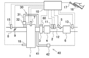
- FIG. FIG. 3 is a diagram illustrating a schematic configuration of an internal combustion engine according to a second embodiment.
- FIG. 6 is another diagram showing a schematic configuration of the internal combustion engine according to the second embodiment.
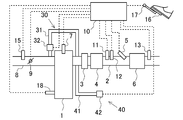
- FIG. 1 is a diagram illustrating a schematic configuration of an internal combustion engine according to the present embodiment.
- An internal combustion engine 1 shown in FIG. 1 is a diesel engine.
- the exhaust passage 2 is connected to the internal combustion engine 1.
- an oxidation catalyst 3, a filter 4, a reducing agent injection valve 5, and a selective reduction type NOx catalyst 6 (hereinafter referred to as an SCR catalyst 6) are provided in this order from the upstream side.
- the oxidation catalyst 3 may be any catalyst having an oxidation function, and may be, for example, a three-way catalyst or an occlusion reduction type NOx catalyst.
- the filter 4 collects particulate matter (PM) in the exhaust.
- the filter 4 may carry a catalyst.
- the oxidation catalyst 3 is not always necessary.
- PM As PM is collected by the filter 4, PM gradually accumulates on the filter 4.
- the PM deposited on the filter 4 can be oxidized and removed.
- the temperature of the filter 4 can be raised by supplying unburned fuel (HC or CO) to the oxidation catalyst 3.
- the reducing agent injection valve 5 opens when the reducing agent is injected, and closes when the reducing agent injection is stopped.
- Ammonia (NH 3 ) is used as the reducing agent.
- the reducing agent injection valve 5 may inject ammonia or urea.
- the urea injected from the reducing agent injection valve 5 is hydrolyzed by the heat of the exhaust or the heat from the SCR catalyst 6 to become ammonia, and is adsorbed on the SCR catalyst 6.
- This ammonia is used as a reducing agent in the SCR catalyst 6. That is, a substance that changes to ammonia or ammonia is supplied from the reducing agent injection valve 5.
- Ammonia or urea may be supplied in any state of gas, liquid (aqueous solution), and solid.
- the reducing agent injection valve 5 corresponds to the supply device in the present invention. Further, in the present embodiment, description will be made assuming that urea water is injected from the reducing agent injection valve 5.
- the SCR catalyst 6 has a function of adsorbing a reducing agent and selectively reducing NOx by the adsorbing reducing agent when NOx passes. Therefore, if ammonia is adsorbed in advance as a reducing agent on the SCR catalyst 6, NOx can be reduced with ammonia in the SCR catalyst 6.
- a temperature sensor 11 for detecting the temperature of the exhaust and an upstream NOx sensor 12 for detecting the NOx concentration in the exhaust are attached to the exhaust passage 2 downstream of the filter 4 and upstream of the SCR catalyst 6. It has been.
- the temperature sensor 11 can detect the temperature of the filter 4 or the temperature of the SCR catalyst 6.
- the upstream NOx sensor 12 can detect the NOx concentration in the exhaust gas flowing into the SCR catalyst 6.
- a downstream NOx sensor 13 that detects the NOx concentration in the exhaust is attached to the exhaust passage 2 downstream of the SCR catalyst 6.
- a temperature sensor may be attached downstream from the SCR catalyst 6 and the temperature of the SCR catalyst 6 may be detected by the temperature sensor. Further, the temperature of the SCR catalyst 6 can be estimated based on the operating state of the internal combustion engine 1. For example, since the engine speed, the fuel injection amount, the intake air amount, and the temperature of the SCR catalyst 6 have a correlation, these relationships may be obtained in advance through experiments or the like and mapped. In this embodiment, the temperature sensor 11 corresponds to the temperature detection device in the present invention.
- the internal combustion engine 1 is provided with a fuel injection valve 7 for injecting fuel into the cylinder.
- An intake passage 8 is connected to the internal combustion engine 1.
- a throttle 9 for adjusting the intake air amount of the internal combustion engine 1 is provided.
- An air flow meter 15 that detects the intake air amount of the internal combustion engine 1 is attached to the intake passage 8 upstream of the throttle 9.
- the internal combustion engine 1 is provided with an EGR device 30 that recirculates a part of the exhaust gas flowing through the exhaust passage 2 to the intake passage 8.
- the EGR device 30 includes an EGR passage 31 that connects the exhaust passage 2 upstream of the oxidation catalyst 3 and the intake passage 8 downstream of the throttle 9, and an EGR valve 32 that adjusts the cross-sectional area of the EGR passage 31. ing.
- the internal combustion engine 1 configured as described above is provided with an ECU 10 that is an electronic control unit for controlling the internal combustion engine 1.
- the ECU 10 controls the internal combustion engine 1 in accordance with the operating conditions of the internal combustion engine 1 and the driver's request.
- the ECU 10 outputs an electric signal corresponding to the amount of depression of the accelerator pedal 16 by the driver to detect the engine load, and an accelerator position sensor 17 for detecting the engine speed. 18 are connected via electric wiring, and output signals of these various sensors are input to the ECU 10.
- the reducing agent injection valve 5, the fuel injection valve 7, the throttle 9, and the EGR valve 32 are connected to the ECU 10 via electric wiring, and the ECU 10 opens and closes the opening and closing timings of the reducing agent injection valve 5 and the fuel injection valve 7.
- the opening degree of the throttle 9 and the EGR valve 32 is controlled.
- the ECU 10 adjusts the ratio of the NO 2 amount to the total NOx amount flowing into the SCR catalyst 6 according to the temperature of the SCR catalyst 6.
- NOx is mainly because consisting of NO and NO 2 Prefecture, may adjust the ratio between NO and NO 2.
- the SCR catalyst 6 cannot reduce NOx unless the temperature is raised to some extent. That is, NOx cannot be purified until the temperature of the SCR catalyst 6 reaches a temperature at which NOx can be purified.
- NOx cannot be purified until the temperature of the SCR catalyst 6 reaches a temperature at which NOx can be purified.
- NO 2 and ammonia first react, and when the temperature rises further, NO and NO 2 become ammonia and react. That is, NO and NO 2 have different minimum temperatures for reacting with ammonia in the SCR catalyst 6.
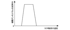
- FIG. 2 is a diagram showing a general relationship between the temperature of the SCR catalyst 6 and the NOx purification rate.
- the NOx include NO and NO 2.
- the temperature of the SCR catalyst 6 is, for example, 180 ° C. or higher, and the NOx purification capability of the SCR catalyst 6 can be maintained high. However, even below 180 ° C., NO 2 and ammonia react to produce ammonium nitrate.
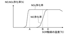
- FIG. 3 is a graph showing the relationship between the temperature of the SCR catalyst 6 and the NO and NO 2 purification rates.
- the temperature indicated by A in FIG. 3 is the temperature when the purification rate of NO 2 becomes high.
- the temperature indicated by B is a temperature after the NO 2 purification rate is increased and in the middle of the NO purification rate being increased.
- the temperature indicated by C is the temperature when the NO purification rate becomes high.
- the ECU 10 increases the ratio of NO 2 in NOx flowing into the SCR catalyst 6 (increases the NO 2 amount).
- the amount of unburned fuel (HC, CO) discharged from the internal combustion engine 1 the amount of NO 2 is increased, and the unburned fuel (HC, CO) discharged from the internal combustion engine 1 is increased.
- NO may be oxidized to NO 2.
- oxygen reacts more easily with HC and CO than NO
- the presence of HC and CO in the exhaust inhibits oxidation of NO. Therefore, NO oxidation can be promoted by reducing the amount of HC and CO in the exhaust.
- the ECU 10 advances the timing of the main injection in the fuel injection valve 7 in order to reduce the unburned fuel discharged from the internal combustion engine 1, or the sub injection (after injection) after the main injection. Reduce the amount. Note that after-injection may be stopped.
- a temperature rising combustion mode which is a combustion mode for increasing the temperature of the catalyst.
- the timing of the main injection in the fuel injection valve 7 is retarded, after-injection is performed after the main injection, or the amount of the after-injection is increased.
- This is a combustion mode in which the fuel is discharged or a gas having a high temperature is discharged from the internal combustion engine 1.
- the unburned fuel can be oxidized on the catalyst and the temperature of the catalyst can be raised.
- This temperature rising combustion mode is carried out until the temperatures of the oxidation catalyst 3 and the SCR catalyst 6 become sufficiently high.
- the main injection timing and the engine timing are determined according to the operating state (engine speed and engine load) of the internal combustion engine 1.
- the after injection amount is determined.
- a combustion mode is hereinafter referred to as a normal combustion mode.
- the oxidation of NO is promoted by reducing the discharge amount of unburned fuel as compared with the case where the temperature rising combustion mode is performed.
- the amount of unburned fuel discharged is equal to or higher than the normal combustion mode and lower than the temperature rising combustion mode.
- Such a combustion mode is hereinafter referred to as an ammonium nitrate production combustion mode.
- the temperature rising combustion mode is carried out. In some cases, the normal combustion mode was implemented.
- the temperature rising combustion mode is first implemented. When the temperature indicated by A is reached, the ammonium nitrate production combustion mode is performed, and in B When the temperature is higher than the indicated temperature, the temperature rising combustion mode is executed until the temperature indicated by C (for example, 180 ° C.) is reached, and when the temperature is higher than the temperature indicated by C, the normal combustion mode is executed.
- the amount of unburned fuel (HC, CO) flowing into the oxidation catalyst 3 or the SCR catalyst 6 is reduced.
- NO oxidation can be promoted to increase the ratio of NO 2 in NOx.
- more ammonium nitrate can be generated in the SCR catalyst 6, so that NOx can be prevented from passing through the SCR catalyst 6. That is, the NOx purification rate in the SCR catalyst 6 can be improved.
- the temperature at which the purification ratio of NO 2 becomes sufficiently high as A although the start of the ammonium nitrate product combustion mode from the temperature of the A, instead of this, the NO 2
- the ammonium nitrate production combustion mode may be started from a temperature at which the purification rate starts to rise. It is also possible to start the ammonium nitrate product combustion mode during increase of purification rate of NO 2.
- the ammonium nitrate production combustion mode may be started from the temperature at which ammonium nitrate production begins to the temperature at which the amount of ammonium nitrate production is maximized.
- the higher the temperature at which the ammonium nitrate production combustion mode is started the more the temperature rise of the oxidation catalyst 3 and the SCR catalyst 6 can be promoted, but the production amount of ammonium nitrate is reduced. For this reason, there is a possibility that the amount of NOx discharged into the atmosphere increases.
- the optimum value of the temperature at which the ammonium nitrate production combustion mode is started may be obtained in advance by experiment or simulation in consideration of the NOx emission amount into the atmosphere and the fuel consumption, and stored in the ECU 10. For example, the temperature at which the ammonium nitrate production combustion mode is started may be determined so that the amount of NOx flowing out from the SCR catalyst 6 is reduced as a whole. Further, this temperature may be changed according to the operating conditions.
- the temperature rising combustion mode is carried out after reaching the temperature of B.
- the temperature rising combustion mode is started at a temperature between the temperature at which the increase in the NO purification rate starts and the temperature at which the NO purification rate becomes sufficiently high (the temperature of C).
- the optimum value of the temperature at which the temperature rising combustion mode is started may be obtained in advance by experiment or simulation in consideration of the NOx emission amount into the atmosphere and the fuel consumption, and stored in the ECU 10.
- the temperature at which the temperature rising combustion mode is started may be determined so that the amount of NOx flowing out from the SCR catalyst 6 is reduced as a whole. Further, this temperature may be changed according to the operating conditions.
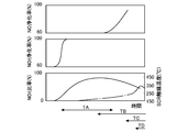
- FIG. 4 is a time chart showing changes in the NO purification rate, the NO 2 purification rate, and the NO 2 ratio.
- the NO 2 ratio is a ratio between NO and NO 2 , and becomes larger as NO 2 increases with respect to NO.
- a one-dot chain line indicates the temperature of the SCR catalyst 6.
- TA is a period during which the reaction (1) occurs, and is a period during which ammonium nitrate is generated in the SCR catalyst 6.
- TB is a period during which the temperature of the SCR catalyst 6 is, for example, 180 ° C. or higher, and is a period during which the reaction (2) occurs.
- TC is a period during which the temperature of the SCR catalyst 6 is, for example, 220 ° C. or higher, and is a period during which the reaction (3) occurs.
- TD is a period in which the temperature of the SCR catalyst 6 is 280 ° C. or higher, for example, and is a period in which the reaction (4) occurs.
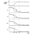
- FIG. 5 shows the temperature of the SCR catalyst 6, the amount of HC discharged from the internal combustion engine 1, the amount of CO, the NOx concentration downstream of the SCR catalyst 6 (may be referred to as NOx amount), and the NO downstream of the SCR catalyst 6. It is a time chart which showed transition of concentration (it is good also as NO amount).
- the temperature of the SCR catalyst 6 has reached the temperature A.
- the temperature of the SCR catalyst 6 reaches the temperature B.
- the temperature of the SCR catalyst 6 has reached the temperature of C.
- the solid line shows the case where the ammonium nitrate production combustion mode is implemented in the period from TA1 to TB1
- the one-dot chain line shows the case where the temperature rising combustion mode is implemented instead of the ammonium nitrate production combustion mode in the period from TA1 to TB1. Yes.
- the ammonium nitrate production combustion mode is performed in the period from TA1 to TB1
- the temperature rising combustion mode is performed in the period from TB1 to TC1
- the normal combustion mode is performed in the period after TC1.
- the temperature rising combustion mode is performed in the period from TA1 to TC1
- the normal combustion mode is performed in the period after TC1.
- the temperature of the SCR catalyst 6 is increased by increasing the amount of HC and CO discharged from the internal combustion engine 1 after the time TA1.
- the HC and CO are oxidized in the oxidation catalyst 3 and the SCR catalyst 6, the amount of oxygen in the exhaust gas decreases. For this reason, oxidation of NO is suppressed.
- NO and ammonia do not react with the SCR catalyst 6, so that NO passes through the SCR catalyst 6. That is, the NOx concentration and the NO concentration downstream of the SCR catalyst 6 are relatively high.
- solid line during the period from TA1 to TB1, HC, since the emissions of CO is reduced, the NO 2 reacts with oxygen and NO is in the oxidation catalyst 3 and the SCR catalyst 6 production Is done. That is, at this temperature, the amount of NO that passes through the SCR catalyst 6 can be reduced, and the amount of NO 2 that reacts with ammonia to generate ammonium nitrate in the SCR catalyst 6 can be increased. Thereby, the NOx concentration and the NO concentration downstream of the SCR catalyst 6 become relatively low.
- the amount of ammonia adsorbed on the SCR catalyst 6 decreases as the amount of ammonium nitrate produced increases. Further, until the temperature of the SCR catalyst 6 reaches the temperature B, the ammonia adsorption amount cannot be increased because urea is not changed even if urea water is supplied. Further, ammonium nitrate is decomposed at about 210 ° C. and removed from the SCR catalyst 6. However, when the amount of ammonium nitrate generated is increased, it takes time until all ammonium nitrate is decomposed. And in the location where ammonium nitrate exists in the SCR catalyst 6, ammonia cannot be adsorbed.
- the amount of ammonium nitrate produced is limited so that the amount of adsorbed ammonia necessary for keeping the NOx purification rate within the allowable range can be maintained.
- the ECU 10 estimates the amount of ammonium nitrate generated by the SCR catalyst 6 (hereinafter also referred to as ammonium nitrate generation amount) and the amount of ammonia adsorbed by the SCR catalyst 6 (hereinafter also referred to as ammonia adsorption amount). The production of ammonium nitrate is suppressed so that the ammonia adsorption amount at which the NOx purification rate falls within the allowable range can be maintained.
- the value obtained by subtracting the ammonium nitrate production amount from the ammonia adsorption amount prior to the production of ammonium nitrate is the current ammonia adsorption amount, and when the current ammonia adsorption amount becomes less than the threshold value, ammonium nitrate production occurs.
- the combustion mode is terminated and the temperature rising combustion mode is entered.
- the threshold value may be an ammonia adsorption amount that is a lower limit value of the allowable range of the NOx purification rate, or may be a value that has a certain margin for the ammonia adsorption amount that is the lower limit value.
- the normal combustion mode may be entered.
- the ammonia adsorption amount at the present time may be a value obtained by subtracting the ammonia amount consumed for producing ammonium nitrate from the ammonia adsorption amount before producing ammonium nitrate.
- the threshold value may be an ammonia adsorption amount at which the discharge amount of N 2 O becomes the upper limit value of the allowable range, or a value with a certain margin for the ammonia adsorption amount at which the upper limit value is reached.
- the amount of ammonium nitrate produced may be estimated as if all NO 2 flowing into the SCR catalyst 6 changes to ammonium nitrate, but can also be estimated as changing to ammonium nitrate at a predetermined rate.
- the NO 2 flowing into the SCR catalyst 6 also includes NO 2 that is generated by oxidizing NO in the SCR catalyst 6.
- the amount of NO 2 flowing into the SCR catalyst 6 is obtained based on the amount of NO and NO 2 discharged from the internal combustion engine 1 and the amount oxidized from NO to NO 2 in the oxidation catalyst 3 and the SCR catalyst 6. .
- the amount oxidized from NO to NO 2 by the oxidation catalyst 3 and the SCR catalyst 6 is calculated based on the temperature of the SCR catalyst 6, the flow rate of exhaust gas determined from the intake air amount, and the like. Further, the amount of ammonia consumed to produce ammonium nitrate can be calculated based on the estimated amount of ammonium nitrate produced.
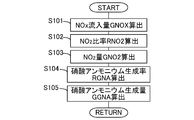
- FIG. 6 is a flowchart showing a flow for calculating the ammonium nitrate production amount GGNA. This routine is repeatedly executed by the ECU 10 every predetermined time.
- the ECU 10 that processes the flow shown in FIG. 6 corresponds to the ammonium nitrate amount detection device in the present invention.
- step S101 the amount of NOx flowing into the SCR catalyst 6 (NOx inflow amount GNOX) is calculated.
- the NOx inflow amount GNOX can be calculated based on the NOx concentration in the exhaust gas flowing into the SCR catalyst 6 detected by the upstream NOx sensor 12 and the intake air amount detected by the air flow meter 15. .
- the operating state (engine speed, fuel injection amount, etc.) of the internal combustion engine 1 and the NOx inflow amount GNOX are correlated, these relationships are obtained in advance through experiments or simulations and mapped and stored in the ECU 10. You may leave it. Furthermore, it may be calculated using a model based on the oxygen concentration in the intake air.
- step S102 the ratio of NO 2 in NOx flowing into the SCR catalyst 6 (NO 2 ratio RNO2) is calculated. Since the ratio of NO 2 in NOx discharged from the internal combustion engine 1 has a correlation with the engine speed, the fuel injection amount, the temperature in the cylinder, and the like, these relationships are obtained in advance through experiments or simulations and mapped. It can be obtained by storing it in the ECU 10. Further, NO is oxidized in the oxidation catalyst 3 and the SCR catalyst 6 to increase the ratio of NO 2 . On the other hand, HC, ratio of NO 2 is lowered by the reduction of NO 2 by CO. Thus, the change in the ratio of NO 2 in each catalyst is calculated as the correction coefficient RCNO2.
- Correction coefficient RCNO2 includes oxide content of NO in the catalyst, HC, is determined in consideration of the reduction amount of NO 2 by the CO. Since the correction coefficient RCNO2 is correlated with the temperature of each catalyst, the amount of HC and CO flowing into each catalyst, the flow rate of exhaust gas, and the like, these relationships are obtained in advance through experiments or simulations and mapped. By multiplying the correction coefficient RCNO2 the ratio of NO 2 in NOx discharged from the internal combustion engine 1, can be obtained NO 2 ratio RNO2.
- step S103 the NO 2 amount GNO2 flowing into the SCR catalyst 6 is calculated.
- the NO 2 amount GNO2 flowing into the SCR catalyst 6 is calculated by multiplying the NOx inflow amount GNOX calculated in step S101 by the NO 2 ratio RNO2 calculated in step S102.
- step S104 the ratio (ammonium nitrate production rate RGNA) at which NO 2 changes to ammonium nitrate in the SCR catalyst 6 is calculated. Since the ammonium nitrate production rate RGNA has a correlation with the temperature of the SCR catalyst 6, these relationships are obtained in advance through experiments or simulations, mapped, and stored in the ECU 10.
- FIG. 7 is a graph showing the relationship between the temperature of the SCR catalyst 6 and the ammonium nitrate production rate RGNA.
- the ammonium nitrate production rate RGNA changes according to the temperature of the SCR catalyst 6.
- the exhaust gas flow rate increases, the ammonium nitrate production rate RGNA decreases. Therefore, a two-dimensional map considering the exhaust gas flow rate may be used.
- step S105 the ammonium nitrate production amount GGNA is calculated.
- the ammonium nitrate generation amount GGNA is calculated by multiplying the NO 2 amount GNO2 flowing into the SCR catalyst 6 calculated in step S103 by the ammonium nitrate generation rate RGNA calculated in step S104. Since the ammonium nitrate production amount GGNA is calculated as a production amount per unit time, the total amount of ammonium nitrate production can be calculated by integrating these values.
- the amount of ammonia consumed to produce ammonium nitrate may be calculated based on the ammonium nitrate production amount GGNA.
- the amount of ammonium nitrate adsorbed on the SCR catalyst 6 may be calculated by subtracting the amount of ammonium nitrate GDNA decomposed in the SCR catalyst 6 from the integrated value of the ammonium nitrate production amount GGNA calculated in step S105. it can. Since the amount GDNA of ammonium nitrate decomposed in the SCR catalyst 6 has a correlation with the temperature of the SCR catalyst 6, these relationships may be obtained in advance through experiments or simulations, mapped, and stored in the ECU 10.
- FIG. 8 is a graph showing the relationship between the temperature of the SCR catalyst 6 and the decomposition amount of ammonium nitrate.
- the temperature of the SCR catalyst 6 increases to some extent, the higher the temperature of the SCR catalyst 6, the greater the decomposition amount of ammonium nitrate per unit time.
- a two-dimensional map may be used in consideration of the remaining amount of ammonium nitrate.
- the amount of decomposition increases as the exhaust flow rate increases, the amount of decomposition may be corrected according to the exhaust flow rate.
- the ammonium nitrate production amount GGNA can be calculated as follows.
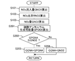
- FIG. 9 is a flowchart showing another flow for calculating the ammonium nitrate production amount GGNA. This routine is repeatedly executed by the ECU 10 every predetermined time. In addition, about the step where the same process as the above-mentioned flow is made, the same code
- step S201 the amount of ammonium nitrate that can be generated in the SCR catalyst 6 (amount of ammonium nitrate that can be generated GPGNA) is calculated.
- the amount of ammonium nitrate that can be generated GPGNA is the amount of ammonium nitrate that can be generated to the maximum per unit time in the SCR catalyst 6 determined from the temperature of the SCR catalyst 6 at the present time.
- NO 2 flowing into the SCR catalyst 6 exceeding the ammonium nitrate-producing amount GPGNA flows out of the SCR catalyst 6 without changing to ammonium nitrate.
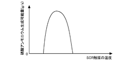
- FIG. 10 is a graph showing the relationship between the temperature of the SCR catalyst 6 and the ammonium nitrate-producing amount GPGNA.
- the ammonium nitrate production possible amount GPGNA changes according to the temperature of the SCR catalyst 6.
- the ammonium nitrate-producing amount GPGNA decreases. Therefore, correction may be performed according to the exhaust gas flow rate.
- step S202 it is determined whether or not the ammonium nitrate-producing amount GPGNA calculated in step S201 is equal to or less than the amount when the NO 2 amount GNO2 flowing into the SCR catalyst 6 calculated in step S103 is changed to ammonium nitrate. The If an affirmative determination is made in step S202, the process proceeds to step S203, where the ammonium nitrate production amount GGNA is equal to the ammonium nitrate production potential GPGNA.
- step S202 the process proceeds to step S204, and the ammonium nitrate generation amount GGNA is calculated assuming that the NO 2 amount GNO2 flowing into the SCR catalyst 6 calculated in step S103 has all changed to ammonium nitrate. .
- the ammonia adsorption amount before the start of the ammonium nitrate production combustion mode can be a target value of the ammonia adsorption amount in the normal combustion mode. That is, in the normal combustion mode, ammonia is supplied so that the ammonia adsorption amount becomes the target value.
- the ammonia adsorption amount is calculated by subtracting the ammonia consumption amount obtained from the NOx purification rate from the ammonia supply amount integration value so that the ammonia adsorption amount becomes the target value.
- Supply ammonia The supply amount of ammonia can be obtained based on the valve opening time of the reducing agent injection valve 5.
- the NOx purification rate can be obtained from, for example, the NOx concentration upstream of the SCR catalyst 6 and the NOx concentration downstream of the SCR catalyst 6. And even if the internal combustion engine 1 is stopped, the ammonia adsorption amount does not change. Therefore, when the ammonium nitrate production combustion mode is started, the ammonia adsorption amount can be handled as a target value. The ammonia adsorption amount can also be obtained by a known technique.
- FIG. 11 is a graph showing the relationship between the ammonia adsorption amount (NH 3 adsorption amount) and the NOx purification rate in the SCR catalyst 6. As the ammonia adsorption amount increases, the NOx purification rate increases.
- the ECU 10 supplies the reducing agent from the reducing agent injection valve 5 with the ammonia adsorption amount indicated by H in FIG. 11 as a target value. And when ammonium nitrate is produced
- the ammonia adsorption amount indicated by E in FIG. 11 is obtained.
- the ammonia adsorption amount indicated by F is an ammonia adsorption amount at which the NOx purification rate becomes the lower limit value of the allowable range. That is, the ammonia adsorption amount is desirably maintained at F or higher.
- the ammonium nitrate production combustion mode when the ammonia adsorption amount decreases to the value G in FIG. 11, the ammonium nitrate production combustion mode is terminated.
- the value of G in FIG. 11 is a value larger than the value of F, and is a value having a margin with respect to the value of F so that the ammonia adsorption amount does not decrease to the value of F.
- the ammonium nitrate production combustion mode may be terminated.
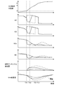
- FIG. 12 shows the temperature of the SCR catalyst 6, the amount of HC discharged from the internal combustion engine 1, the amount of CO, the NOx concentration on the downstream side of the SCR catalyst 6 (may be the NOx amount), and the downstream side of the SCR catalyst 6.
- 6 is a time chart showing transitions of NO concentration (which may be NO amount), the amount of ammonium nitrate adsorbed by the SCR catalyst 6 (ammonium nitrate deposition amount), and the amount of ammonia adsorption. It is assumed that the amount of ammonium nitrate deposited is equal to the amount of ammonium nitrate produced.
- the temperature of the SCR catalyst 6 has reached the temperature A.
- time TB1 the temperature of the SCR catalyst 6 reaches the temperature B.
- the temperature of the SCR catalyst 6 has reached the temperature of C.
- the solid line indicates the case where the ammonium nitrate production combustion mode is terminated when the ammonia adsorption amount is less than the threshold
- the broken line is the case where the ammonium nitrate production combustion mode is not terminated when the ammonia adsorption amount is less than the threshold
- the alternate long and short dash line indicates a case where the temperature rising combustion mode is performed instead of the ammonium nitrate production combustion mode (in the case of the alternate long and short dash line in FIG. 5).
- the ammonia nitrate generation combustion mode is not terminated when the ammonia adsorption amount becomes less than the threshold value (broken line), the ammonia adsorption amount further decreases after the time point TA2, so that the NOx purification rate is increased after the time point TB1. As a result, the amount of NOx and NO emissions increases.
- the NOx emission amount in the period from TA2 to TB1 is larger than that in the broken line, but the NOx emission amount after TC1 is smaller than that in the broken line. .
- the NOx discharge amount as a whole can be made smaller than the case of a broken line.
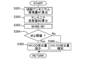
- FIG. 13 is a flowchart showing a control flow of the SCR catalyst 6 according to the present embodiment at a low temperature. This routine is executed every predetermined time by the ECU 10 in the ammonium nitrate production combustion mode.
- step S301 the ammonium nitrate deposition amount M1 is calculated.
- the ammonium nitrate deposition amount M1 is the amount of ammonium nitrate adsorbed by the SCR catalyst 6, and is calculated as being equal to the amount of ammonium nitrate produced.
- the amount of ammonia consumed to produce ammonium nitrate may be calculated based on the amount of ammonium nitrate produced.
- an ammonia adsorption amount M2 before ammonium nitrate is generated is calculated.
- the ammonia adsorption amount M2 may be an ammonia adsorption amount at the start of the internal combustion engine 1 or may be an ammonia adsorption amount at the start of the reduction of the HC and CO emission amounts. Since urea does not change to ammonia until the temperature of the SCR catalyst 6 reaches the temperature indicated by B after the internal combustion engine 1 is started, ammonia cannot be supplied to the SCR catalyst 6. Further, when the temperature of the SCR catalyst 6 is lower than A, ammonia does not react in the SCR catalyst 6, so that the ammonia adsorption amount does not decrease.
- step S303 the ammonia adsorption amount M at the present time is calculated by subtracting the ammonium nitrate accumulation amount M1 calculated in step S301 from the ammonia adsorption amount M2 calculated in step S302.
- step S303 the ammonia adsorption amount M at the present time is calculated by subtracting the “ammonia amount consumed to produce ammonium nitrate” calculated in step S301 from the ammonia adsorption amount M2 calculated in step S302. May be.
- step S304 it is determined whether the current ammonia adsorption amount M is equal to or greater than a threshold value.
- the threshold value may be an ammonia adsorption amount that is a lower limit value of the allowable range of the NOx purification rate, or may be a value that has some allowance for the ammonia adsorption amount that is the lower limit value. That is, in this step, instead of determining whether or not the current ammonia adsorption amount M is equal to or greater than the threshold value, the NOx purification rate estimated from the ammonia amount currently adsorbed by the SCR catalyst 6 is equal to or greater than the threshold value. It may be determined whether or not there is.
- the threshold value of the NOx purification rate may be the lower limit value of the allowable range of the NOx purification rate, or may be a value with a certain margin.
- step S304 If an affirmative determination is made in step S304, the process proceeds to step S305. On the other hand, if a negative determination is made, the process proceeds to step S306.
- step S305 the emission amount of HC and CO from the internal combustion engine 1 is reduced, and the ammonium nitrate production combustion mode is performed.
- the ECU 10 that processes step S305 corresponds to the control device in the present invention.
- step S306 the emission amount of HC and CO from the internal combustion engine 1 is increased, and the temperature rising combustion mode is performed. That is, the ammonium nitrate production combustion mode is terminated, and the temperature rising combustion mode suitable for increasing the catalyst temperature is entered.
- step S304 it is determined in step S304 whether or not the current ammonia adsorption amount M is equal to or greater than the threshold value. Instead, the integrated value of the ammonium nitrate production amount is less than or equal to a predetermined value. It may be determined whether or not there is. That is, when the integrated value of the production amount of ammonium nitrate exceeds a predetermined value, it may be determined that the NOx purification rate cannot be maintained within the allowable range due to the small ammonia adsorption amount.
- FIG. 14 is a flowchart showing a control flow when the SCR catalyst 6 according to the present embodiment is at a low temperature and taking the temperature of the SCR catalyst 6 into consideration. This routine is executed every predetermined time by the ECU 10 when the SCR catalyst 6 is at a low temperature.
- symbol is attached
- step S401 is executed after the process of step S303.
- step S401 it is determined whether or not the temperature of the SCR catalyst 6 is A or higher. That is, it is determined whether or not the temperature of the SCR catalyst 6 has reached the temperature at which ammonium nitrate is generated.
- step S401 If an affirmative determination is made in step S401, the process proceeds to step S304. On the other hand, if a negative determination is made in step S401, ammonium nitrate cannot be generated in the SCR catalyst 6 and NOx cannot be purified, so this routine is terminated. In this case, you may implement temperature rising combustion mode.
- step S402 is executed after step S305 or step S306.
- step S402 it is determined whether or not the temperature of the SCR catalyst 6 is B or higher. That is, it is determined whether or not the temperature at which ammonium nitrate is generated in the SCR catalyst 6 and NO and NO 2 are reduced has been reached.
- step S402 If an affirmative determination is made in step S402, the process proceeds to step S403. On the other hand, if a negative determination is made in step S402, the process returns to step S401.
- step S403 the emission amount of HC and CO is increased, and the temperature rising combustion mode is performed. That is, the amount of HC and CO discharged from the internal combustion engine 1 is relatively increased to oxidize HC and CO in the oxidation catalyst 3 and the like, and the temperature of the SCR catalyst 6 is raised by the heat generated at this time. At this time, since NO and NO 2 are reduced in the SCR catalyst 6, it is not necessary to increase the ratio of NO 2 in NOx.
- step S404 it is determined whether or not the temperature of the SCR catalyst 6 is C or higher. That is, it is determined whether or not the SCR catalyst 6 has reached a temperature at which the SCR catalyst 6 is fully activated and can exhibit its original purification performance. If an affirmative determination is made in step S404, the process proceeds to step S405. On the other hand, if a negative determination is made, the process returns to step S402.
- step S405 the temperature rising combustion mode of the SCR catalyst 6 is terminated, and the routine proceeds to the normal combustion mode.
- the main injection amount, the main injection, the after injection timing, the after injection amount, and the like are adjusted based on the operating state of the internal combustion engine 1 (for example, the engine speed and the engine load). These relationships are obtained and mapped in advance by experiments or the like so that the fuel consumption and the engine output are in an optimum state. Thereafter, this routine is terminated.
- the oxidation catalyst 3 is provided. However, since HC and CO are also oxidized in the SCR catalyst 6, even if the oxidation catalyst 3 is not provided, it flows into the SCR catalyst 6. By reducing the amount of unburned fuel, the oxidation of NO can be promoted.
- the emission of HC and CO from the internal combustion engine 1 is suppressed by the advance of the fuel injection timing or the decrease of the after injection amount, but the HC and CO are reduced by other methods. May be. A plurality of methods may be combined.
- the EGR gas amount may be smaller in the ammonium nitrate production combustion mode than in the temperature rising combustion mode. That is, the opening degree of the EGR valve 32 may be reduced during the ammonium nitrate production combustion mode. Further, the supply of EGR gas may be stopped during the ammonium nitrate production combustion mode. As a result, the combustion state becomes more stable, and the amount of unburned fuel discharged from the internal combustion engine 1 can be reduced. Thereby, oxidation of NO can be promoted.
- the HC and CO amounts flowing into the oxidation catalyst 3 and the SCR catalyst 6 may be reduced without changing the HC and CO amounts discharged from the internal combustion engine 1.
- a fuel addition valve for adding fuel to the exhaust passage 2 upstream from the oxidation catalyst 3 the fuel addition is performed in the ammonium nitrate production combustion mode rather than in the temperature rising combustion mode.
- the amount of fuel added from the valve may be reduced.
- fuel addition from the fuel addition valve may be stopped during the ammonium nitrate production combustion mode. Thereby, since it can suppress that a fuel reacts with oxygen in the oxidation catalyst 3 and the SCR catalyst 6, oxidation of NO can be promoted.
- the SCR catalyst 6 cannot purify NO, but at a temperature at which NO 2 reacts with ammonia to produce ammonium nitrate, the HC, CO in the exhaust gas
- the amount of NO in the exhaust gas can be decreased and the amount of NO 2 can be increased.
- the NO 2 and ammonia in the SCR catalyst 6 it can be suppressed NOx flows out of the SCR catalyst 6. That is, the amount of NOx released into the atmosphere can be reduced.
- the production of ammonium nitrate is limited so that the NOx purification rate after the activation of the SCR catalyst 6 is within the allowable range, the amount of NOx discharged into the atmosphere as a whole is reduced. Can do.
- Example 2 In Example 1, the oxidation of NO is promoted by reducing the amount of HC and CO flowing into the oxidation catalyst 3 and the SCR catalyst 6. On the other hand, in this embodiment, the oxidation of NO is promoted by increasing the oxygen concentration in the exhaust gas. This embodiment can be carried out simultaneously with the above embodiment.
- FIG. 15 is a diagram showing a schematic configuration of the internal combustion engine according to the present embodiment.
- the same devices as those in FIG. 1 are denoted by the same reference numerals and description thereof is omitted.
- a secondary air supply device 40 for supplying secondary air to the exhaust passage 2 upstream of the oxidation catalyst 3 is provided.
- the secondary air supply device 40 includes a secondary air supply passage 41 connected to the exhaust passage 2 and a pump 42 connected to the secondary air supply passage 41 and discharging air.
- the pump 42 is controlled by the ECU 10.
- the oxidation of NO flowing into the oxidation catalyst 3 and the SCR catalyst 6 can be promoted by increasing the oxygen concentration in the exhaust gas. Thereby, since the production amount of ammonium nitrate in the SCR catalyst 6 increases, it is possible to suppress the release of NOx into the atmosphere.
- the NOx purification rate of the SCR catalyst 6 is estimated from the amount of ammonia adsorbed is less than the threshold value, it is possible to suppress the formation of ammonium nitrate by reducing the amount of NO 2. That is, by reducing the amount of oxygen flowing into the catalyst having an oxidation function, the oxidation of NO is suppressed, so that the amount of NO 2 can be reduced. Thereby, the fall of a NOx purification rate can be suppressed.
- the oxygen concentration in the exhaust can be increased by reducing the amount of EGR gas, and the oxygen concentration in the exhaust can be increased by increasing the amount of EGR gas. Can be lowered.
- the supply of EGR gas may be stopped. Further, the opening of the throttle 9 may be increased. That is, the oxygen concentration in the exhaust gas can be increased by increasing the amount of oxygen discharged from the internal combustion engine 1 or by supplying oxygen into the exhaust gas.
- the EGR device 30 or the secondary air supply device 40 corresponds to the oxygen supply device in the present invention.
- the EGR gas amount or secondary air amount, and the opening degree of the throttle 9 may be determined to be optimum values through experiments or simulations. Further, the EGR gas amount or the secondary air amount and the opening degree of the throttle 9 may be adjusted according to the temperature of the oxidation catalyst 3 or the temperature of the SCR catalyst 6.
- the heating device which raises the temperature of the oxidation catalyst 3 or the SCR catalyst 6.
- the NO can be quickly raised to a temperature at which it can be oxidized.
- ammonium nitrate can be generated at an early stage.
- the heating device is controlled by the ECU 10.
- FIG. 16 is another diagram showing a schematic configuration of the internal combustion engine according to the present embodiment.
- An electric heater 60 for heating the oxidation catalyst 3 is provided as a heating device.
- the electric heater 60 is controlled by the ECU 10.
- the electric heater 60 may generate heat due to the electric resistance of the carrier by energizing the carrier of the oxidation catalyst 3. Further, the electric heater 60 may be provided in the SCR catalyst 6.
- the temperature of the oxidation catalyst 3 or the SCR catalyst 6 can be increased by the electric heater 60.
- a combustion heater may be used.
- the turbocharger and a passage that bypasses the turbine of the turbocharger are provided, the exhaust gas is allowed to flow through the passage that bypasses the turbine, thereby suppressing the temperature drop of the exhaust gas in the turbine. That is, the temperature of the oxidation catalyst 3 or the SCR catalyst 6 may be raised, and the temperature drop of the exhaust gas may be suppressed.
- the heating of the oxidation catalyst 3 or the SCR catalyst 6 may be performed until the temperature reaches any one of the above A, B, and C.
- an electric heater, a combustion heater, and a bypass passage that bypasses the turbine correspond to the heat supply device in the present invention.
- reaction time in the catalyst may be secured by reducing the flow rate of the exhaust gas passing through the oxidation catalyst 3 and the SCR catalyst 6.
- the intake air amount may be reduced, or the supercharging pressure may be reduced.
- the amount of EGR gas may be increased.
Landscapes
- Engineering & Computer Science (AREA)
- Chemical & Material Sciences (AREA)
- Chemical Kinetics & Catalysis (AREA)
- Combustion & Propulsion (AREA)
- Health & Medical Sciences (AREA)
- General Engineering & Computer Science (AREA)
- Mechanical Engineering (AREA)
- Analytical Chemistry (AREA)
- Toxicology (AREA)
- Biomedical Technology (AREA)
- Oil, Petroleum & Natural Gas (AREA)
- General Chemical & Material Sciences (AREA)
- Environmental & Geological Engineering (AREA)
- Materials Engineering (AREA)
- Exhaust Gas After Treatment (AREA)
- Exhaust Gas Treatment By Means Of Catalyst (AREA)
Abstract
Priority Applications (5)
| Application Number | Priority Date | Filing Date | Title |
|---|---|---|---|
| JP2014545652A JP5880731B2 (ja) | 2012-11-07 | 2013-10-28 | 内燃機関の排気浄化装置 |
| IN3792DEN2015 IN2015DN03792A (fr) | 2012-11-07 | 2013-10-28 | |
| EP13853801.2A EP2918805B1 (fr) | 2012-11-07 | 2013-10-28 | Dispositif de purification de gaz d'échappement pour un moteur à combustion interne |
| US14/440,163 US9593611B2 (en) | 2012-11-07 | 2013-10-28 | Exhaust gas control apparatus for internal combustion engine |
| CN201380057818.0A CN104769244B (zh) | 2012-11-07 | 2013-10-28 | 内燃机的排气净化装置 |
Applications Claiming Priority (2)
| Application Number | Priority Date | Filing Date | Title |
|---|---|---|---|
| JP2012245210 | 2012-11-07 | ||
| JP2012-245210 | 2012-11-07 |
Publications (1)
| Publication Number | Publication Date |
|---|---|
| WO2014073408A1 true WO2014073408A1 (fr) | 2014-05-15 |
Family
ID=50684517
Family Applications (1)
| Application Number | Title | Priority Date | Filing Date |
|---|---|---|---|
| PCT/JP2013/079137 WO2014073408A1 (fr) | 2012-11-07 | 2013-10-28 | Dispositif de purification de gaz d'échappement pour un moteur à combustion interne |
Country Status (6)
| Country | Link |
|---|---|
| US (1) | US9593611B2 (fr) |
| EP (1) | EP2918805B1 (fr) |
| JP (1) | JP5880731B2 (fr) |
| CN (1) | CN104769244B (fr) |
| IN (1) | IN2015DN03792A (fr) |
| WO (1) | WO2014073408A1 (fr) |
Cited By (2)
| Publication number | Priority date | Publication date | Assignee | Title |
|---|---|---|---|---|
| JP2016044591A (ja) * | 2014-08-22 | 2016-04-04 | いすゞ自動車株式会社 | 内燃機関及び内燃機関の排気ガス浄化方法 |
| JP2019019793A (ja) * | 2017-07-20 | 2019-02-07 | いすゞ自動車株式会社 | Scrシステム |
Families Citing this family (22)
| Publication number | Priority date | Publication date | Assignee | Title |
|---|---|---|---|---|
| US9604177B2 (en) * | 2012-03-07 | 2017-03-28 | Toyota Jidosha Kabushiki Kaisha | Exhaust gas purification apparatus for an internal combustion engine |
| SE540265C2 (sv) * | 2014-01-31 | 2018-05-15 | Scania Cv Ab | Förfarande och system vid tillförsel av tillsatsmedel till en avgasström |
| FR3041688B1 (fr) * | 2015-09-29 | 2019-05-10 | Ge Energy Products France Snc | Procede et installation de controle de la quantite de particules solides emises par une turbine a combustion |
| WO2017198292A1 (fr) * | 2016-05-18 | 2017-11-23 | Volvo Truck Corporation | Système de traitement des gaz d'échappement à chauffage inductif |
| SE540088C2 (en) * | 2016-07-14 | 2018-03-20 | Scania Cv Ab | Method and system for use when correcting supply of an additive to an exhaust gas stream |
| SE540140C2 (en) | 2016-07-14 | 2018-04-10 | Scania Cv Ab | Method and system for diagnosing an aftertreatment components subjected to an exhaust gas stream |
| SE540087C2 (en) | 2016-07-14 | 2018-03-20 | Scania Cv Ab | A system and a method for diagnosing the performance of two NOx sensors in an exhaust gas processing configuration comprising two SCR units |
| SE541557C2 (en) | 2016-07-14 | 2019-10-29 | Scania Cv Ab | Method and system for diagnosing an aftertreatment system |
| US10961889B2 (en) * | 2016-07-29 | 2021-03-30 | Cummins Inc. | Methods and systems for removing deposits in an aftertreatment system |
| JP2018131984A (ja) * | 2017-02-16 | 2018-08-23 | トヨタ自動車株式会社 | 内燃機関の排気浄化装置 |
| DE102017218322A1 (de) * | 2017-10-13 | 2019-04-18 | Continental Automotive Gmbh | Verfahren zum Betreiben einer Abgasnachbehandlungsanlage eines Dieselmotors mit Emissionssteuerung in Abhängigkeit vom gespeicherten NH3 |
| CN110486125B (zh) * | 2019-08-20 | 2021-05-07 | 北京汽车集团越野车有限公司 | 一种燃油发动机催化剂起燃控制方法和系统 |
| DE102019216520A1 (de) * | 2019-10-28 | 2021-04-29 | Robert Bosch Gmbh | Verfahren zur Anpassung der Dosierung von Reduktionsmittel in einem SCR-Katalysator |
| US11725560B2 (en) | 2020-07-21 | 2023-08-15 | Paccar Inc | Heater control in heavy-duty motor vehicle engines |
| US11879367B2 (en) | 2020-07-21 | 2024-01-23 | Paccar Inc | NOx sensor diagnostics in heavy-duty motor vehicle engines |
| US11326493B2 (en) | 2020-07-21 | 2022-05-10 | Paccar Inc | Ammonia storage capacity of SCR catalyst unit |
| US11352927B2 (en) | 2020-07-21 | 2022-06-07 | Paccar Inc | Control of selective catalytic reduction in heavy-duty motor vehicle engines |
| US11499463B2 (en) | 2020-07-21 | 2022-11-15 | Paccar Inc | Methods for evaluating diesel exhaust fluid quality |
| US11976582B2 (en) | 2020-07-21 | 2024-05-07 | Paccar Inc | Methods for diagnostics and operation of an emissions aftertreatment system |
| US11428136B2 (en) | 2020-07-21 | 2022-08-30 | Paccar Inc | Heater diagnostics in heavy-duty motor vehicle engines |
| US11181026B1 (en) | 2020-07-21 | 2021-11-23 | Paccar Inc | Methods for operation of an emissions aftertreatment system for NOx control during regeneration of diesel particulate filter |
| US11725555B1 (en) * | 2022-02-07 | 2023-08-15 | Caterpillar Inc. | Aftertreatment system |
Citations (6)
| Publication number | Priority date | Publication date | Assignee | Title |
|---|---|---|---|---|
| JP2004346794A (ja) | 2003-05-21 | 2004-12-09 | Mitsubishi Fuso Truck & Bus Corp | 内燃機関の排気浄化装置 |
| JP2005256727A (ja) * | 2004-03-11 | 2005-09-22 | Nissan Diesel Motor Co Ltd | エンジンの排気浄化装置 |
| JP2006320854A (ja) | 2005-05-20 | 2006-11-30 | Hino Motors Ltd | 選択還元型触媒及びそれを用いたエンジンの排ガス浄化装置 |
| JP2010101237A (ja) | 2008-10-23 | 2010-05-06 | Mitsubishi Fuso Truck & Bus Corp | 排気浄化装置 |
| JP2011102573A (ja) | 2009-11-12 | 2011-05-26 | Ud Trucks Corp | 排気浄化装置 |
| JP2012031787A (ja) | 2010-07-30 | 2012-02-16 | Toyota Motor Corp | 内燃機関の排気浄化装置及び方法 |
Family Cites Families (11)
| Publication number | Priority date | Publication date | Assignee | Title |
|---|---|---|---|---|
| JP3529645B2 (ja) | 1998-11-27 | 2004-05-24 | リンナイ株式会社 | 排気装置 |
| DE10007048A1 (de) * | 2000-02-17 | 2001-08-23 | Volkswagen Ag | Vorrichtung und Verfahren zur Ermittlung einer Regenerationsnotwendigkeit eines NO¶x¶-Speicherkatalysators |
| JP4267538B2 (ja) | 2004-08-23 | 2009-05-27 | 日野自動車株式会社 | 排気浄化装置 |
| US7765800B2 (en) | 2004-08-23 | 2010-08-03 | Hino Motors, Ltd. | Exhaust gas purification apparatus |
| US8713917B2 (en) * | 2007-08-30 | 2014-05-06 | GM Global Technology Operations LLC | Method for reducing NH3 release from SCR catalysts during thermal transients |
| KR101048125B1 (ko) * | 2008-11-14 | 2011-07-08 | 현대자동차주식회사 | 차량의 요소 분사량 제어장치 및 방법 |
| WO2011030433A1 (fr) * | 2009-09-10 | 2011-03-17 | トヨタ自動車株式会社 | Système de commande pour moteur à combustion interne |
| JP2011226402A (ja) * | 2010-04-21 | 2011-11-10 | Nippon Soken Inc | 排気浄化装置 |
| US8733083B2 (en) * | 2010-04-26 | 2014-05-27 | Cummins Filtration Ip, Inc. | SCR catalyst ammonia surface coverage estimation and control |
| EP2783741B1 (fr) * | 2011-01-26 | 2021-03-31 | Ford Global Technologies, LLC | Catalyseurs SCR et LNT pour des applications LNT-SCR combinées |
| DE102011013183A1 (de) | 2011-03-05 | 2012-09-06 | Daimler Ag | Lachgasoptimiertes Abgasnachbehandlungssystem einer Kraftfahrzeug-Brennkraftmaschine und Betriebsverfahren hierfür |
-
2013
- 2013-10-28 EP EP13853801.2A patent/EP2918805B1/fr not_active Not-in-force
- 2013-10-28 WO PCT/JP2013/079137 patent/WO2014073408A1/fr active Application Filing
- 2013-10-28 IN IN3792DEN2015 patent/IN2015DN03792A/en unknown
- 2013-10-28 JP JP2014545652A patent/JP5880731B2/ja active Active
- 2013-10-28 CN CN201380057818.0A patent/CN104769244B/zh not_active Expired - Fee Related
- 2013-10-28 US US14/440,163 patent/US9593611B2/en active Active
Patent Citations (6)
| Publication number | Priority date | Publication date | Assignee | Title |
|---|---|---|---|---|
| JP2004346794A (ja) | 2003-05-21 | 2004-12-09 | Mitsubishi Fuso Truck & Bus Corp | 内燃機関の排気浄化装置 |
| JP2005256727A (ja) * | 2004-03-11 | 2005-09-22 | Nissan Diesel Motor Co Ltd | エンジンの排気浄化装置 |
| JP2006320854A (ja) | 2005-05-20 | 2006-11-30 | Hino Motors Ltd | 選択還元型触媒及びそれを用いたエンジンの排ガス浄化装置 |
| JP2010101237A (ja) | 2008-10-23 | 2010-05-06 | Mitsubishi Fuso Truck & Bus Corp | 排気浄化装置 |
| JP2011102573A (ja) | 2009-11-12 | 2011-05-26 | Ud Trucks Corp | 排気浄化装置 |
| JP2012031787A (ja) | 2010-07-30 | 2012-02-16 | Toyota Motor Corp | 内燃機関の排気浄化装置及び方法 |
Non-Patent Citations (1)
| Title |
|---|
| See also references of EP2918805A4 |
Cited By (2)
| Publication number | Priority date | Publication date | Assignee | Title |
|---|---|---|---|---|
| JP2016044591A (ja) * | 2014-08-22 | 2016-04-04 | いすゞ自動車株式会社 | 内燃機関及び内燃機関の排気ガス浄化方法 |
| JP2019019793A (ja) * | 2017-07-20 | 2019-02-07 | いすゞ自動車株式会社 | Scrシステム |
Also Published As
| Publication number | Publication date |
|---|---|
| IN2015DN03792A (fr) | 2015-10-02 |
| US20150314239A1 (en) | 2015-11-05 |
| EP2918805A1 (fr) | 2015-09-16 |
| CN104769244B (zh) | 2017-05-10 |
| EP2918805A4 (fr) | 2015-12-09 |
| EP2918805B1 (fr) | 2017-06-21 |
| US9593611B2 (en) | 2017-03-14 |
| JP5880731B2 (ja) | 2016-03-09 |
| CN104769244A (zh) | 2015-07-08 |
| JPWO2014073408A1 (ja) | 2016-09-08 |
Similar Documents
| Publication | Publication Date | Title |
|---|---|---|
| JP5880731B2 (ja) | 内燃機関の排気浄化装置 | |
| US8875497B2 (en) | Exhaust purification system for internal combustion engine | |
| US8978367B2 (en) | Exhaust gas purifying system of internal combustion engine | |
| JP4900002B2 (ja) | 内燃機関の排気浄化システム | |
| US8359830B2 (en) | Exhaust purification device of an internal combustion engine | |
| US20110265457A1 (en) | Exhaust purifying device for internal combustion engine | |
| EP2513439B1 (fr) | Procédé pour commander le niveau de tampon de réducteur dans un dispositif de post-traitement de gaz d'échappement | |
| JP2008163856A (ja) | 内燃機関の排気浄化装置 | |
| CN104379889A (zh) | 内燃机的排气净化装置 | |
| JP2012017674A (ja) | 内燃機関の排気浄化装置 | |
| JP5910759B2 (ja) | 内燃機関の排気浄化システム | |
| JP2010053703A (ja) | 排気浄化装置 | |
| JP5915516B2 (ja) | 内燃機関の排気浄化装置 | |
| JP2016079852A (ja) | 内燃機関の排気浄化装置の異常判定システム | |
| EP3342998B1 (fr) | Appareil de purification de gaz d'échappement pour moteur à combustion interne | |
| JP2014105664A (ja) | 内燃機関の排気浄化システム | |
| JP2012031787A (ja) | 内燃機関の排気浄化装置及び方法 | |
| JP2014137044A (ja) | 内燃機関の排気浄化装置 | |
| JP5126141B2 (ja) | 内燃機関の排気浄化装置 | |
| WO2013190657A1 (fr) | Dispositif de purification des gaz d'échappement pour un moteur à combustion interne | |
| JP6453702B2 (ja) | 排気浄化機構の異常診断装置 | |
| JP2013238164A (ja) | 内燃機関の排気浄化装置 | |
| JP2018035766A (ja) | 内燃機関の排気浄化装置 |
Legal Events
| Date | Code | Title | Description |
|---|---|---|---|
| 121 | Ep: the epo has been informed by wipo that ep was designated in this application |
Ref document number: 13853801 Country of ref document: EP Kind code of ref document: A1 |
|
| ENP | Entry into the national phase |
Ref document number: 2014545652 Country of ref document: JP Kind code of ref document: A |
|
| WWE | Wipo information: entry into national phase |
Ref document number: 14440163 Country of ref document: US |
|
| REEP | Request for entry into the european phase |
Ref document number: 2013853801 Country of ref document: EP |
|
| WWE | Wipo information: entry into national phase |
Ref document number: 2013853801 Country of ref document: EP |
|
| NENP | Non-entry into the national phase |
Ref country code: DE |