WO2014073052A1 - 内燃機関の排ガス浄化装置 - Google Patents
内燃機関の排ガス浄化装置 Download PDFInfo
- Publication number
- WO2014073052A1 WO2014073052A1 PCT/JP2012/078836 JP2012078836W WO2014073052A1 WO 2014073052 A1 WO2014073052 A1 WO 2014073052A1 JP 2012078836 W JP2012078836 W JP 2012078836W WO 2014073052 A1 WO2014073052 A1 WO 2014073052A1
- Authority
- WO
- WIPO (PCT)
- Prior art keywords
- exhaust gas
- forced regeneration
- flow rate
- dpf
- gas flow
- Prior art date
Links
Images


Classifications
-
- F—MECHANICAL ENGINEERING; LIGHTING; HEATING; WEAPONS; BLASTING
- F01—MACHINES OR ENGINES IN GENERAL; ENGINE PLANTS IN GENERAL; STEAM ENGINES
- F01N—GAS-FLOW SILENCERS OR EXHAUST APPARATUS FOR MACHINES OR ENGINES IN GENERAL; GAS-FLOW SILENCERS OR EXHAUST APPARATUS FOR INTERNAL COMBUSTION ENGINES
- F01N3/00—Exhaust or silencing apparatus having means for purifying, rendering innocuous, or otherwise treating exhaust
- F01N3/02—Exhaust or silencing apparatus having means for purifying, rendering innocuous, or otherwise treating exhaust for cooling, or for removing solid constituents of, exhaust
- F01N3/021—Exhaust or silencing apparatus having means for purifying, rendering innocuous, or otherwise treating exhaust for cooling, or for removing solid constituents of, exhaust by means of filters
- F01N3/023—Exhaust or silencing apparatus having means for purifying, rendering innocuous, or otherwise treating exhaust for cooling, or for removing solid constituents of, exhaust by means of filters using means for regenerating the filters, e.g. by burning trapped particles
-
- F—MECHANICAL ENGINEERING; LIGHTING; HEATING; WEAPONS; BLASTING
- F02—COMBUSTION ENGINES; HOT-GAS OR COMBUSTION-PRODUCT ENGINE PLANTS
- F02D—CONTROLLING COMBUSTION ENGINES
- F02D41/00—Electrical control of supply of combustible mixture or its constituents
- F02D41/02—Circuit arrangements for generating control signals
- F02D41/14—Introducing closed-loop corrections
- F02D41/1438—Introducing closed-loop corrections using means for determining characteristics of the combustion gases; Sensors therefor
- F02D41/1444—Introducing closed-loop corrections using means for determining characteristics of the combustion gases; Sensors therefor characterised by the characteristics of the combustion gases
- F02D41/1445—Introducing closed-loop corrections using means for determining characteristics of the combustion gases; Sensors therefor characterised by the characteristics of the combustion gases the characteristics being related to the exhaust flow
-
- F—MECHANICAL ENGINEERING; LIGHTING; HEATING; WEAPONS; BLASTING
- F01—MACHINES OR ENGINES IN GENERAL; ENGINE PLANTS IN GENERAL; STEAM ENGINES
- F01N—GAS-FLOW SILENCERS OR EXHAUST APPARATUS FOR MACHINES OR ENGINES IN GENERAL; GAS-FLOW SILENCERS OR EXHAUST APPARATUS FOR INTERNAL COMBUSTION ENGINES
- F01N3/00—Exhaust or silencing apparatus having means for purifying, rendering innocuous, or otherwise treating exhaust
- F01N3/02—Exhaust or silencing apparatus having means for purifying, rendering innocuous, or otherwise treating exhaust for cooling, or for removing solid constituents of, exhaust
- F01N3/021—Exhaust or silencing apparatus having means for purifying, rendering innocuous, or otherwise treating exhaust for cooling, or for removing solid constituents of, exhaust by means of filters
- F01N3/033—Exhaust or silencing apparatus having means for purifying, rendering innocuous, or otherwise treating exhaust for cooling, or for removing solid constituents of, exhaust by means of filters in combination with other devices
- F01N3/035—Exhaust or silencing apparatus having means for purifying, rendering innocuous, or otherwise treating exhaust for cooling, or for removing solid constituents of, exhaust by means of filters in combination with other devices with catalytic reactors, e.g. catalysed diesel particulate filters
-
- F—MECHANICAL ENGINEERING; LIGHTING; HEATING; WEAPONS; BLASTING
- F01—MACHINES OR ENGINES IN GENERAL; ENGINE PLANTS IN GENERAL; STEAM ENGINES
- F01N—GAS-FLOW SILENCERS OR EXHAUST APPARATUS FOR MACHINES OR ENGINES IN GENERAL; GAS-FLOW SILENCERS OR EXHAUST APPARATUS FOR INTERNAL COMBUSTION ENGINES
- F01N9/00—Electrical control of exhaust gas treating apparatus
- F01N9/002—Electrical control of exhaust gas treating apparatus of filter regeneration, e.g. detection of clogging
-
- F—MECHANICAL ENGINEERING; LIGHTING; HEATING; WEAPONS; BLASTING
- F02—COMBUSTION ENGINES; HOT-GAS OR COMBUSTION-PRODUCT ENGINE PLANTS
- F02D—CONTROLLING COMBUSTION ENGINES
- F02D41/00—Electrical control of supply of combustible mixture or its constituents
- F02D41/0002—Controlling intake air
-
- F—MECHANICAL ENGINEERING; LIGHTING; HEATING; WEAPONS; BLASTING
- F02—COMBUSTION ENGINES; HOT-GAS OR COMBUSTION-PRODUCT ENGINE PLANTS
- F02D—CONTROLLING COMBUSTION ENGINES
- F02D41/00—Electrical control of supply of combustible mixture or its constituents
- F02D41/02—Circuit arrangements for generating control signals
- F02D41/14—Introducing closed-loop corrections
- F02D41/1438—Introducing closed-loop corrections using means for determining characteristics of the combustion gases; Sensors therefor
- F02D41/1444—Introducing closed-loop corrections using means for determining characteristics of the combustion gases; Sensors therefor characterised by the characteristics of the combustion gases
- F02D41/1446—Introducing closed-loop corrections using means for determining characteristics of the combustion gases; Sensors therefor characterised by the characteristics of the combustion gases the characteristics being exhaust temperatures
-
- F—MECHANICAL ENGINEERING; LIGHTING; HEATING; WEAPONS; BLASTING
- F02—COMBUSTION ENGINES; HOT-GAS OR COMBUSTION-PRODUCT ENGINE PLANTS
- F02D—CONTROLLING COMBUSTION ENGINES
- F02D41/00—Electrical control of supply of combustible mixture or its constituents
- F02D41/30—Controlling fuel injection
- F02D41/38—Controlling fuel injection of the high pressure type
- F02D41/40—Controlling fuel injection of the high pressure type with means for controlling injection timing or duration
- F02D41/401—Controlling injection timing
-
- F—MECHANICAL ENGINEERING; LIGHTING; HEATING; WEAPONS; BLASTING
- F02—COMBUSTION ENGINES; HOT-GAS OR COMBUSTION-PRODUCT ENGINE PLANTS
- F02D—CONTROLLING COMBUSTION ENGINES
- F02D41/00—Electrical control of supply of combustible mixture or its constituents
- F02D41/30—Controlling fuel injection
- F02D41/38—Controlling fuel injection of the high pressure type
- F02D41/40—Controlling fuel injection of the high pressure type with means for controlling injection timing or duration
- F02D41/402—Multiple injections
- F02D41/405—Multiple injections with post injections
-
- F—MECHANICAL ENGINEERING; LIGHTING; HEATING; WEAPONS; BLASTING
- F01—MACHINES OR ENGINES IN GENERAL; ENGINE PLANTS IN GENERAL; STEAM ENGINES
- F01N—GAS-FLOW SILENCERS OR EXHAUST APPARATUS FOR MACHINES OR ENGINES IN GENERAL; GAS-FLOW SILENCERS OR EXHAUST APPARATUS FOR INTERNAL COMBUSTION ENGINES
- F01N2900/00—Details of electrical control or of the monitoring of the exhaust gas treating apparatus
- F01N2900/04—Methods of control or diagnosing
- F01N2900/0408—Methods of control or diagnosing using a feed-back loop
-
- F—MECHANICAL ENGINEERING; LIGHTING; HEATING; WEAPONS; BLASTING
- F01—MACHINES OR ENGINES IN GENERAL; ENGINE PLANTS IN GENERAL; STEAM ENGINES
- F01N—GAS-FLOW SILENCERS OR EXHAUST APPARATUS FOR MACHINES OR ENGINES IN GENERAL; GAS-FLOW SILENCERS OR EXHAUST APPARATUS FOR INTERNAL COMBUSTION ENGINES
- F01N2900/00—Details of electrical control or of the monitoring of the exhaust gas treating apparatus
- F01N2900/06—Parameters used for exhaust control or diagnosing
- F01N2900/14—Parameters used for exhaust control or diagnosing said parameters being related to the exhaust gas
- F01N2900/1411—Exhaust gas flow rate, e.g. mass flow rate or volumetric flow rate
-
- F—MECHANICAL ENGINEERING; LIGHTING; HEATING; WEAPONS; BLASTING
- F01—MACHINES OR ENGINES IN GENERAL; ENGINE PLANTS IN GENERAL; STEAM ENGINES
- F01N—GAS-FLOW SILENCERS OR EXHAUST APPARATUS FOR MACHINES OR ENGINES IN GENERAL; GAS-FLOW SILENCERS OR EXHAUST APPARATUS FOR INTERNAL COMBUSTION ENGINES
- F01N2900/00—Details of electrical control or of the monitoring of the exhaust gas treating apparatus
- F01N2900/06—Parameters used for exhaust control or diagnosing
- F01N2900/16—Parameters used for exhaust control or diagnosing said parameters being related to the exhaust apparatus, e.g. particulate filter or catalyst
- F01N2900/1602—Temperature of exhaust gas apparatus
-
- F—MECHANICAL ENGINEERING; LIGHTING; HEATING; WEAPONS; BLASTING
- F01—MACHINES OR ENGINES IN GENERAL; ENGINE PLANTS IN GENERAL; STEAM ENGINES
- F01N—GAS-FLOW SILENCERS OR EXHAUST APPARATUS FOR MACHINES OR ENGINES IN GENERAL; GAS-FLOW SILENCERS OR EXHAUST APPARATUS FOR INTERNAL COMBUSTION ENGINES
- F01N2900/00—Details of electrical control or of the monitoring of the exhaust gas treating apparatus
- F01N2900/06—Parameters used for exhaust control or diagnosing
- F01N2900/16—Parameters used for exhaust control or diagnosing said parameters being related to the exhaust apparatus, e.g. particulate filter or catalyst
- F01N2900/1606—Particle filter loading or soot amount
-
- Y—GENERAL TAGGING OF NEW TECHNOLOGICAL DEVELOPMENTS; GENERAL TAGGING OF CROSS-SECTIONAL TECHNOLOGIES SPANNING OVER SEVERAL SECTIONS OF THE IPC; TECHNICAL SUBJECTS COVERED BY FORMER USPC CROSS-REFERENCE ART COLLECTIONS [XRACs] AND DIGESTS
- Y02—TECHNOLOGIES OR APPLICATIONS FOR MITIGATION OR ADAPTATION AGAINST CLIMATE CHANGE
- Y02T—CLIMATE CHANGE MITIGATION TECHNOLOGIES RELATED TO TRANSPORTATION
- Y02T10/00—Road transport of goods or passengers
- Y02T10/10—Internal combustion engine [ICE] based vehicles
- Y02T10/40—Engine management systems
Definitions
- the present invention relates to an exhaust gas processing apparatus provided with an internal combustion engine, in particular an exhaust gas passage of a diesel engine, including a pre-stage oxidation catalyst and a filter for collecting particulate matter.
- PM particle matter, Particulate contained in exhaust gas as a countermeasure against black smoke of diesel engine DPF (Diesel Particulate) to collect matter Filter) is used, but in order to burn off the collected PM periodically, the PM deposition amount inside the DPF is estimated, and when it reaches a predetermined amount, the temperature of exhaust gas is forcedly raised, Forced regeneration of the DPF is performed to burn and remove the PM.
- DPF Diesel Particulate
- Patent documents 1 JP, 2011-153591, A
- patent documents 2 JP, A, 2003-206726
- Patent Document 1 determines that the DPF abnormal combustion occurrence operated when the internal combustion engine is the transition from the operating range ⁇ of the high rotation state or a high load to the low rotation low-load operating region set time T 1 to beta.
- the intake throttle valve 4 is fully opened to increase the exhaust gas flow rate, and the DPF filter device is cooled by heat removal by sensible heat of the exhaust gas, and late post injection is continued.
- the oxygen concentration around the DPF filter is reduced to suppress abnormal combustion of PM collected by the DPF filter.
- Patent Document 2 when transitioning to a low load rotation region where the exhaust flow rate of the engine decreases during regeneration of the DPF, the burner is operated to supply the combustion gas to the turbine of the turbocharger, and the turbine A technique has been disclosed that increases work to promote supercharging, and promotes heat release of the DPF to suppress excessive temperature rise as the exhaust flow rate of the engine increases.
- the excessive rise in temperature of DPF during forced regeneration can occur even when the exhaust gas flow rate changes to a low operating state immediately after the regeneration is started once at the operating point where the load is relatively low, so that Patent Document 1 high rotational state or the high-load operation region of ⁇ when shifting to the low rotation low-load operating region within the set time T 1 to ⁇ just determined that DPF abnormal combustion occurrence operation, the DPF during forced regeneration over as It is not possible to accurately determine the operating condition that causes the temperature rise.
- Patent Document 2 when the engine exhaust flow rate shifts to a low load rotation region where the exhaust flow rate decreases, the burner is operated to supply combustion gas to the turbine of the turbocharger to increase the turbine work.
- the overheat due to the excessive temperature increase can be increased by installing burners and accessories accompanying this, and the DPF device becomes larger. If the mounting space is small, installation is difficult.
- the present invention provides an exhaust gas purification apparatus for removing PM in exhaust gas by providing a pre-stage oxidation catalyst and DPF in an exhaust gas passage of an internal combustion engine.
- An object of the present invention is to prevent temperature rise and to prevent damage due to thermal melting and cracking of the DPF, and to prevent increase in regeneration frequency of forced regeneration to reduce fuel consumption and oil dilution.
- the present invention provides a pre-stage oxidation catalyst and a DPF in an exhaust gas passage of an internal combustion engine to collect PM in exhaust gas on the DPF and burn the collected PM to the DPF.
- the forced regeneration control means for controlling the forced regeneration of the DPF by controlling the opening degree of the intake throttle valve and the post injection amount or the injection time, and the forced regeneration processing by the forced regeneration control means, the exhaust gas flow rate is less than the first threshold
- the exhaust gas flow rate is increased when the exhaust gas flow rate is determined to be less than the first threshold value and greater than or equal to the second threshold value by the first determination means for determining whether the second threshold value is smaller than the first threshold value and the first determination means
- the exhaust gas flow control means for controlling the intake throttle valve, a second determination means for determining the operating state of the exhaust gas flow rate less than the second threshold value, and the second determination means determining that the exhaust gas flow rate is less than the second threshold value
- the excessive temperature rise of the DPF during forced regeneration can occur even if the exhaust gas flow rate changes to a low operating state immediately after the start of regeneration once it is started, so from the high load area Even if there is no significant load change to the low load area, the exhaust gas flow rate which is small during forced regeneration and which may cause the temperature rise of the DPF during regeneration processing, is calculated in advance by test or simulation.
- the first threshold and the second threshold are set, and it is determined that there is a risk that the temperature rise of the DPF may occur if the operating state is less than the first threshold and is more than the second threshold but smaller than the first threshold.
- the intake throttle valve is controlled to increase the exhaust gas flow rate by the exhaust gas amount increase control means.
- the DPF can be cooled by increasing the exhaust gas amount and carrying away the heat due to the sensible heat of the exhaust gas, that is, the DPF can be cooled by the heat radiation to the exhaust gas. It is possible to prevent damage due to If the exhaust gas flow rate falls below the second threshold value, it is determined that the regeneration can not be continued, and the forced regeneration is interrupted.
- the limit value of the PM deposition amount of forced start can be raised, and the interval of forced regeneration can be increased.
- the forced regeneration interrupting means may interrupt the forced regeneration process when the DPF inlet temperature further exceeds a predetermined value.
- the forced regeneration interrupting means may interrupt the forced regeneration process when the PM deposition amount further exceeds a predetermined value.
- the exhaust gas temperature at the outlet of the DPF is provided separately from the forced regeneration interrupting means, and when the exhaust gas temperature at the inlet or outlet of the pre-stage catalyst becomes lower than a predetermined temperature during the forced regeneration control.
- the system safety means may be provided to interrupt the forced regeneration process based on at least one of the conditions when the post injection time exceeds the predetermined time when the predetermined temperature is exceeded.
- the exhaust gas temperature at the inlet or the outlet of the pre-stage catalyst becomes lower than a predetermined temperature during the forced regeneration control, it is determined that the regeneration can not be continued because the load of the internal combustion engine decreases during forced regeneration and regeneration is performed. Interrupt the process. Further, when the exhaust gas temperature at the outlet of the DPF exceeds a predetermined temperature, it is determined that the PM combustion in the DPF is in the overheat state, and the regeneration process is interrupted. Further, when the post injection time exceeds a predetermined time, the regeneration processing is interrupted to prevent an excessive temperature rise due to excessive injection of the post injection.
- control of the intake throttle valve for increasing the exhaust gas flow rate in the exhaust gas amount increase control means may be such that the intake throttle valve is fully opened.
- control of the intake throttle valve for increasing the exhaust gas flow rate in the exhaust gas amount increasing control stage may control the throttle opening degree with the exhaust gas flow rate of the first threshold as a target exhaust gas flow rate.
- the throttle opening degree is controlled with the exhaust gas flow rate of the first threshold value as the target exhaust gas flow rate, a large change in the exhaust gas flow rate is suppressed and rotation fluctuation of the internal combustion engine is suppressed. It can be suppressed. As a result, the excessive temperature rise prevention operation due to the abnormal combustion of the DPF can be performed without a large degree of rotation of the engine.
- the temperature rise by the intake throttle valve can be expected even with a slight amount, the post injection amount can be reduced, and fuel efficiency deterioration and oil dilution can be reduced.
- the first determination means and the second determination means are determined based on a first determination map and a second determination map respectively representing an operating range represented by the number of revolutions and the torque of the internal combustion engine. It is good.
- the first determination means and the second determination means are constituted by the two-dimensional first determination map and the second determination map represented by the rotational speed and load of the internal combustion engine, the first determination means and the second determination means The state of the exhaust gas flow rate can be determined easily and accurately.
- the first determination map and the second determination map may be configured by one map. As described above, since the first determination map and the second determination map are formed as one map, the storage capacity of the control device can be reduced, and the control device can be simplified.
- the present invention provides an exhaust gas purification apparatus for removing PM in exhaust gas by providing a pre-stage oxidation catalyst and DPF in an exhaust gas passage of an internal combustion engine. At the same time, excessive temperature rise of the DPF is prevented to prevent damage due to thermal dissolution or cracking of the DPF, and the limit value of the PM deposition amount can be increased, and increase of the regeneration frequency of forced regeneration is prevented, fuel efficiency deterioration and oil die Solution can be reduced.
- (A) shows an operating range
- (B) shows the data configuration of the first determination map
- (C) shows the data configuration of the second determination map
- (D) shows the second It is explanatory drawing which shows the data structure which 1 judgment map and 2nd determination map became one.
- FIG. 1 shows an overall configuration of a first embodiment in which an exhaust gas purification apparatus 1 of the present invention is applied to a diesel engine (hereinafter referred to as an engine) 3.
- an engine hereinafter referred to as an engine 3.
- a piston 7 is built in a cylinder 5 of an engine 3, and a combustion chamber 9 is formed above the piston 7.
- An intake pipe 13 and an exhaust pipe 15 are connected to the cylinder head, and an intake valve 17 and an exhaust port in the cylinder head to which the intake pipe 13 and the exhaust pipe 15 are connected are connected to an intake port 17 and a combustion chamber 9.
- An exhaust valve 19 is provided.
- a fuel injector 21 for injecting fuel into the combustion chamber 9 is provided at the upper center of the cylinder head.
- a fuel such as light oil is supplied to the fuel injector 21 at a high pressure from the injector pump 23 via a common rail (pressure accumulator) 25 from the injector pump 23, and the fuel is injected into the combustion chamber 9. Further, the injection timing and the injection amount of the fuel are controlled by a control unit (ECU) 27.
- the injected fuel mixes with the air supplied through the intake pipe 13 and the intake port, and the mixture is compressed in the combustion chamber 9 to be ignited and burned.
- the engine 3 further includes an exhaust turbocharger 33 comprising an exhaust turbine 29 disposed in the exhaust pipe 15 and a compressor 31 disposed in the intake pipe 13 and driven coaxially with the exhaust turbine 29. There is.
- the charge air a discharged from the compressor 31 of the exhaust turbocharger 33 passes through the suction pipe 13 and is cooled by the intercooler 35, and then enters the charge air chamber 37.
- An intake throttle valve 39 is provided on the inlet side of the air supply chamber 37 to control the flow rate of air flowing through the intake pipe 13. Further, in the air supply chamber 37, an air supply pressure sensor 41 and an air supply temperature sensor 43 are provided.
- a downstream oxidation catalyst (DOC) 45 and a DPF (filter device) 47 downstream of the upstream oxidation catalyst 45 are provided in the exhaust pipe 15 downstream of the exhaust turbine 29.
- the combustion gas burned in the combustion chamber 9, that is, the exhaust gas e is discharged to the exhaust pipe 15, and drives the exhaust turbine 29 of the exhaust turbocharger 33 to become a power source of the compressor 31.
- the exhaust gas e passes through the pre-stage oxidation catalyst 45 and the DPF 47, and the PM contained in the exhaust gas e is collected by the DPF 47.
- Exhaust gas e from which PM has been removed by the DPF 47 is discharged to the outside via a muffler (not shown).
- Temperature sensors 49, 51, and 53 for detecting the temperature of the exhaust gas e are respectively provided on the inlet side of the pre-stage oxidation catalyst 45 and the exhaust pipe 15 on the inlet side and the outlet side of the DPF 47, respectively. Further, a differential pressure sensor 55 for detecting a pressure difference between the exhaust gas e at the inlet and the outlet of the DPF 47 is provided, and an intake flow meter (air flow sensor) 57 is provided at the inlet of the intake pipe 13.
- an EGR pipe 59 is provided between the intake pipe 13 and the exhaust pipe 15.
- the EGR pipe 59 is provided with an EGR valve 63 that controls the amount of exhaust gas flowing through the EGR cooler 61 and the EGR pipe 59. Part of the exhaust gas e passes through the EGR pipe 59 and is cooled by the EGR cooler 61 and then returned to the air supply chamber 37. This reduces the amount of oxygen in the supply air, lowering the combustion temperature of the peak, thereby suppressing the occurrence of NO X.
- the detection values of the temperature sensors 49, 51, 53, the differential pressure sensor 55, the intake flow meter 57, and the opening degree signal of the intake throttle valve 39 are input to the control unit (ECU) 27.
- the control device 27 also receives an engine load signal or a fuel injection amount signal and an engine speed signal. Based on these input values, the controller 27 controls the operation of the engine 3 by controlling the fuel injector 21, the injector pump 23, the intake throttle valve 39, the EGR valve 63, and the like.
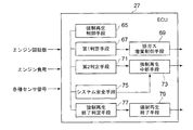
- the control device 27 includes forced regeneration control means 65 for controlling forced regeneration of the DPF 47 by controlling the opening degree of the intake throttle valve 39 and the post injection amount or injection time, and the forced regeneration control means 65.
- First judgment means 67 for judging whether the exhaust gas flow rate is less than the first threshold and more than the second threshold during the forced regeneration process, and the first judgment means determines the exhaust gas flow rate
- Exhaust gas increase control means 69 for controlling the opening degree of the intake throttle valve 39 to increase the exhaust gas flow rate when it is determined that the exhaust gas flow rate is smaller than the first threshold value and larger than the second threshold value
- the forced regeneration interrupting unit 73 for interrupting the forced regeneration process when the exhaust gas flow rate is determined to be less than the second threshold value by the second determining unit 71 that determines the The has.
- the forced regeneration control means 65 starts the regeneration process when a predetermined amount of PM is deposited on the DPF 47.
- the start of regeneration processing is, for example, an estimated value of the PM deposition amount deposited on the DPF, engine operating time, vehicle travel distance, fuel consumption, and further, DPF 47 back and forth pressure
- the difference is detected by the differential pressure sensor 55 and judged based on this pressure difference.
- control is first performed to close the intake throttle valve 39. This control reduces the amount of oil dilution by raising the exhaust temperature and activating the DOC 45 and maintaining the exhaust temperature high. Further, when the DOC 45 is activated and the condition is satisfied, after the main injection of the fuel into the combustion chamber 9, the injection timing is instructed to the fuel injector 21 so as to perform the post injection. As a result, post injection fuel injected after the main injection is discharged to the exhaust pipe 15 without being completely burned.
- the post-injected unburned HC component is oxidized by the catalytic action of the activated upstream oxidation catalyst 45, and the reaction heat generated at that time raises the temperature of the exhaust gas e to approximately 600 ° C. or higher. Then, by setting the exhaust gas e to 600 ° C. or higher, the combustion of the PM collected by the DPF 47 is promoted, and the PM is removed from the DPF 47.
- FIG. 3 shows the operating state of the engine and the change tendency of the exhaust gas flow rate, and shows the reproducible region X and the non-reproducible region Y.
- the region ⁇ in FIG. 3 is a region in which forced regeneration can be continued without abnormal combustion by releasing the closing control of the intake throttle valve 39 and performing valve opening control. That is, when the rotational speed and load of the engine 3 rush into this region ⁇ , the closing control of the intake throttle valve 39 for forced regeneration is canceled and the opening control is performed to increase the exhaust gas flow rate, This is an area where excessive temperature rise can be avoided, and the PM limit deposition amount can be set high according to the increase of the exhaust gas flow rate.
- the exhaust gas amount increase control means 69 cancels and opens the closing control of the intake throttle valve 39 to control the exhaust gas flow amount in the increasing direction so that the regeneration can be continued. .
- the region ⁇ in FIG. 3 is a region where the amount of exhaust gas is small even if the closing control of the intake throttle valve 39 is released and the opening control is performed to increase the exhaust gas flow rate, and it is difficult to avoid excessive temperature rise.
- the second determination means 71 determines whether or not the operating state of the engine 3 has entered the region ⁇ . When it enters the region ⁇ , the forced regeneration interrupting means 73 interrupts the forced regeneration control, releases the closing control of the intake throttle valve 39, and shifts to the opening degree control according to the operating state of the engine 3 , Cancel the post injection command.
- the range of the region ⁇ and the region ⁇ is a range substantially enclosed by the oblique equal exhaust gas flow rate lines L1 and L2 between predetermined engine rotational speeds (R1 to R2).
- the upper boundary lines forming the regions ⁇ and ⁇ are bending lines similar to the exhaust gas flow lines L1 and L2.
- the control device 27 further includes a system safety means 75 and a forced regeneration end determination means 77.
- the system safety means 75 controls the operation state of the engine 3 by the second determination means 71. It is not determined that forced regeneration is interrupted by the result, but the temperature sensor 49, 51 detects the exhaust gas temperature at the inlet or outlet of the pre-stage oxidation catalyst 45 during forced regeneration control. The detected temperature is judged in comparison with the threshold value, and when it is less than the predetermined temperature, the regeneration processing is interrupted when it is determined that the regeneration can not be continued because the engine load is reduced during the forced regeneration. is there.
- the exhaust gas temperature at the outlet of the DPF 47 is detected by the temperature sensor 53 and judged based on the detected temperature, and if it exceeds a predetermined threshold temperature, PM combustion in the DPF 47 is in the overheated state. Determine and interrupt the playback process.
- the injection time by post injection is detected and integrated, and when the integration time exceeds a predetermined time, regeneration is interrupted to prevent excessive temperature rise due to excessive injection of post injection due to HC slip due to blockage of DOC, etc. Do.
- the injection time may be calculated by integrating the number of injections, as long as the injection period can be compared with a predetermined threshold.
- the forced regeneration by the second judging unit 71 is performed by adding the condition for interrupting the forced regeneration processing by the system safety unit 75 separately from the judgment of the forced regeneration interruption by the second judging unit 71 based on the exhaust gas flow rate.
- addition of control for interrupting forced regeneration in a fail-safe manner can reliably prevent damage due to thermal melting or cracking of the DPF 47.
- the forced regeneration end determination unit 77 determines that the forced regeneration is completed when the PM deposition amount decreases to less than a predetermined value after the start of the regeneration and exceeds the predetermined time, and terminates the forced regeneration control. Specifically, the closing control of the intake throttle valve 39 is released, and the injection control of the post injection is released.
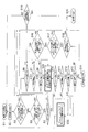
- step S1 When forced regeneration is started in step S1, for example, based on a signal from differential pressure sensor 55 that detects an engine operation time, a travel distance of a vehicle, a fuel consumption amount, and a pressure difference between front and rear of DPF 47, PM When it is determined that the predetermined amount is accumulated and the regeneration is necessary, and the condition of the forced regeneration is satisfied, the forced regeneration control is started in step S2.
- the forced regeneration control is a temperature at which PM of the DPF 47 promotes combustion of the exhaust gas temperature by activation of the pre-stage oxidation catalyst 45 by throttling control of the intake throttle valve 39 and post injection control injected after main injection as described above. Raise temperature to 600 ° C.
- step S3 the post injection time is detected, and it is determined whether the time exceeds the predetermined time t1 and the inlet gas temperature of the DPF 47 is less than the threshold T1 based on the detection signal from the temperature sensor 51. Alternatively, it is simply determined whether the post injection time exceeds the predetermined time t2.
- step S3 If the determination in step S3 is yes, the process proceeds to step S14 to interrupt forced regeneration and prevent burnout due to excessive temperature rise of the DPF 47. In the case of No, the process proceeds to step S4.
- step S4 based on the detection signal from the temperature sensor 53, it is determined whether the gas temperature at the outlet of the DPF 47 exceeds the threshold T2 and the duration time exceeds t3. Alternatively, it is determined whether the outlet gas temperature of the DPF 47 simply exceeds the threshold T3. Based on these determinations, it is determined whether or not PM is in the abnormal combustion state in the DPF 47. If it is in the abnormal combustion state, it is determined as Yes and the process proceeds to step S14 to interrupt forced regeneration and overheat. To prevent. In the case of No, the process proceeds to step S5.
- step S5 it is determined based on the detection signals from the temperature sensors 49 and 51 whether the inlet gas temperature or the outlet gas temperature of the front stage oxidation catalyst (DOC) 45 exceeds the threshold T4. In the case of No, the process proceeds to step S14 to interrupt the forced regeneration. As a result, it is determined that the engine can not be continued during the forced regeneration so that the regeneration can not be continued, and the forced regeneration is interrupted so as not to inject unnecessary post injection, and the forced regeneration control is restarted. Make efficient playback. In the case of Yes, it progresses to step S6.
- control of the basic safety function in forced regeneration control is performed (D section in FIG. 4). That is, control by the system safety means 75 is performed. Note that the control based on the exhaust gas flow rate to prevent excessive temperature rise during forced regeneration, that is, the first determination unit 67 and the second determination unit 71 are performed by steps S6 to S13 and S15 described later (FIG. E part).
- step S6 it is determined based on the detection signal from the temperature sensor 51 whether the inlet gas temperature of the DPF 47 exceeds the threshold T5. If not, the process proceeds to step S19 to determine whether the PM accumulation amount is less than q2 and the forced regeneration time exceeds t4. In the case of Yes, it is determined that the reproduction is completed, and the forced regeneration is completed in Step S20. In the case of No, the process returns to Step S2 and the forced regeneration control is executed again.
- step S6 the PM deposition amount is calculated in step S7, and it is determined whether the deposition amount exceeds the threshold value q1. In the case of No, as in step S6, the process proceeds to step S19. In the case of Yes, it progresses to step S8.
- the PM deposition amount is calculated by integrating the difference between the amount of PM discharged from the engine based on the operating condition and the amount of PM regeneration that is lost in combustion within the DPF 47, the differential pressure across the DPF 47, the fuel injection time, etc. It is calculated and estimated based on operating conditions.
- step S8 it is determined whether the exhaust gas flow rate is less than a threshold value Q1.
- This threshold value Q1 corresponds to the equal exhaust gas flow rate line L1 shown in FIG.
- the exhaust gas flow rate may be a detected value from an intake flow meter (air flow sensor) 57 or an engine speed, a fuel injection amount, an air supply pressure amount from the air supply pressure sensor 41, an air supply temperature signal from the air supply temperature sensor 43, etc. You may use the value calculated and calculated
- step S19 determines whether the reproduction has already been completed.
- step S9 If it is less than the threshold value Q1, that is, if it is Yes, there is a high possibility of entering the non-reproducible region Y of FIG. 3, so the process proceeds to step S9 and the closing control of the intake throttle valve 39 is interrupted. Make the 39 degree of opening fully open.
- the exhaust gas flow rate may be increased by raising the engine speed by other means.
- step S8 the determination as to whether or not it exists in the operation region of region ⁇ or region ⁇ of FIG. 3 based on the engine speed and load is further included. Temperature rise prevention control can be performed. That is, in the determination based on the calculated value of the exhaust gas flow rate, as in the exhaust gas flow rate line L1, L2 shown in FIG. Therefore, by looking at the operating conditions of the engine speed and the load, and using the determination of whether or not it has entered the regions ⁇ and ⁇ , it is possible to more accurately determine whether the exhaust gas flow rate is low and the excess temperature rise is likely to occur. It is possible to determine.
- step S9 After the valve closing control of the intake throttle valve 39 is canceled in step S9, it is determined whether or not the inlet gas temperature of the DPF 47 exceeds the threshold value T5 'based on the detection signal from the temperature sensor 51 in step S10. . If No, it is determined that the PM overheat condition is settled, and the process proceeds to step S15, where the valve closing control of the intake throttle valve 39 is restarted or the increase control of the engine speed is ended to perform forced regeneration Execute control again.
- step S10 it is determined that the overheated state still continues, and it is determined in step S11 whether the PM deposition amount exceeds the threshold value q1. If exceeded, it becomes Yes, and it is judged that the overheated state can occur because the accumulation amount still remains, and the process proceeds to the next step S12, and if not exceeded, it becomes No and it is judged that the excessive temperature rise hardly occurs. Then, the process proceeds to step S15, the closing control of the intake throttle valve 39 is performed again, or the increase control of the engine speed is ended, and the control of forced regeneration is performed again.
- step S12 the exhaust gas flow rate is compared with a threshold value Q1 'larger than the threshold value Q1 to determine whether it is less than Q1'.
- the exhaust gas flow rate is larger than the threshold value Q1, and it is determined that the excessive temperature rise is less likely to occur, and the process proceeds to step S15.
- the process proceeds to step S13, where it is compared with a threshold value Q2 smaller than the threshold value Q1 to determine whether it is larger than the threshold value.
- This threshold value Q2 corresponds to the exhaust gas flow rate line L2 of FIG.
- step S14 the process proceeds to step S14 to interrupt forced regeneration. If NO in step S13, the process proceeds to step S18 to determine whether the PM deposition amount is less than q2 and the forced regeneration time exceeds t4, as in step S19. In step S20, the forced regeneration is completed in step S20. In the case of No, the process proceeds to steps S17 and S16, and the same necessity determination as in the steps S3 and S4 is performed. In the case of Yes, the forced determination is interrupted in step S14.
- step S9 the process returns to step S9, and the closing control of the intake throttle valve 39 is interrupted to be in a fully open state.
- the exhaust gas flow rate may be increased by increasing the engine speed by other means other than by fully opening the intake throttle valve 39.
- T1 500 ° C
- T2 750 ° C
- T3 800 ° C
- T4 240 ° C
- T5 570 ° C
- T5 ' 570 ° C
- q1 4 g / L
- q2 1 g / L
- t1 2 min
- t2 30 min
- t3 10 sec
- t4 10 min
- Q1 100 kg / h
- Q1 ' 120 kg / h
- Q2 70 kg / h. It is.
- the DPF 47 can be cooled by the heat radiation function to prevent temperature rise.
- the exhaust gas flow rate decreases below the second threshold compared to Q2 of the second threshold, it is in the region of regeneration non-permission area Y, so it is determined that regeneration can not be continued and forced regeneration is performed. By interrupting, it is possible to prevent damage due to thermal melting or cracking of the DPF 47.
- the interval of forced regeneration can be increased. By this, it is possible to prevent the forced regeneration interval from being shortened and to increase the regeneration frequency, to suppress an increase in post-injection fuel used at the time of regeneration, and to reduce fuel consumption deterioration and oil dilution.
- the second embodiment is the same as the first embodiment except that steps S9 and S15 in the flowchart of FIG. 4 are replaced with steps S29 and S35, and the other configurations are the same, and therefore the same step code is used. The explanation is omitted.
- step S19 the intake throttle valve 39 is not fully opened, but the intake throttle valve is opened such that Q1 of the exhaust gas flow set as the first threshold is the target exhaust gas flow. Control.
- step S25 the opening degree control of the intake throttle valve 39 with the target exhaust gas flow rate as described above is ended.
- the exhaust gas flow rate of the first threshold value Q1 is set as the target exhaust gas flow rate, and the opening degree of the intake throttle valve 39 is controlled to be the exhaust gas flow rate.
- the large change of the exhaust gas flow rate is suppressed, and the rotational fluctuation of the engine 3 can be suppressed. Therefore, the excessive temperature rise prevention operation due to the abnormal combustion of the DPF 47 can be performed without a large degree of engine rotational knitting. Further, it is possible to suppress an increase in the amount of oil dilution due to a decrease in exhaust temperature due to an excessive opening of the throttle valve.
- step S28 instead of calculating the exhaust gas flow rate in step S28, a region in which the exhaust gas flow rate may decrease to cause excessive temperature rise is set in advance by a two-dimensional map based on the engine speed and load. .
- the region ⁇ is the same as the region described in the first embodiment.
- step S28 it is determined whether the operating state of the engine 3 has entered the operating range ⁇ based on the detection signals of the engine rotational speed and the load.
- step S32 it is determined whether or not the region ⁇ + ⁇ has been entered. If No, it indicates that the exhaust gas flow rate has increased in the region other than ⁇ + ⁇ , that is, in the region where there is no risk of causing excessive temperature rise. Go to S15. If it is determined at step S32 that the vehicle has entered the region ⁇ + ⁇ , the process proceeds to step S33 to determine whether the operating region is ⁇ . If the vehicle has entered the region ⁇ , the process proceeds to step S14. Stop playback. Others are the same as in the first embodiment.
- the first determination map 91 indicating the driving range ⁇ is a two-dimensional map configured by the data array in FIG. 7B
- the second determination map 92 indicating the driving range ⁇ is the one in FIG. 7C. It is a two-dimensional map composed of data arrays.
- the first determination map 91 and the second determination map 92 may be configured as an integrated map 93 formed as a single map, and the integrated map 93 is configured by the data array of FIG. 7D. It is a two-dimensional map.
- the regions ⁇ and ⁇ are respectively constituted by the two-dimensional first determination map 91 and the second determination map 92 represented by the number of rotations and the load of the engine 3.
- the state of the exhaust gas flow rate according to the state can be determined easily and accurately.
- the first determination map 91 and the second determination map 92 be configured by one integrated map 93, and since the first determination map 91 and the second determination map 92 are configured by one integrated map 93, The storage capacity of the control device 27 can be reduced, and the control device 27 can be simplified.
- the present invention in the exhaust gas purification apparatus in which the pre-stage oxidation catalyst and the DPF are provided in the exhaust gas passage of the internal combustion engine to remove PM in the exhaust gas, excessive temperature rise of the DPF is prevented at forced regeneration of the DPF. While preventing damage due to thermal melting and cracking of the DPF and preventing the increase in regeneration frequency of forced regeneration to reduce fuel consumption deterioration and oil dilution, it is useful as an applied technology to an exhaust gas purification device of a diesel engine is there.
- Exhaust gas purification device 3 Engine (internal combustion engine) 11 intake pipe 15 exhaust pipe (exhaust gas passage) 21 fuel injector 27 control unit (ECU) 39 Intake throttle valve (intake throttle valve) 45 Pre-stage oxidation catalyst 47 DPF 65 Forced Regeneration Control Means 67 First Determination Means 69 Exhaust Gas Increase Control Means 71 Second Determination Means 73 Forced Regeneration Interrupting Means 75 System Safety Means 77 Forced Regeneration End Determination Means 79 Forced Regeneration End Means 91 First Determination Map 92 Second Determination Map 93 Integrated map ⁇ , ⁇ Operation area X Reproduction permission area Y Reproduction non-permission area Z Reproduction boundary area L1, L2 etc. Exhaust gas flow rate line
Abstract
Description
Matter)を捕集するために、DPF(Diesel Particulate
Filter)が使用されているが、捕集されたPMを定期的に燃焼除去するため、DPF内部のPM堆積量を推定して所定量に達したら排気ガスの温度を強制的に上昇させて、PMを燃焼除去するDPFの強制再生が行われる。
これは、再生間隔が短くなり、再生頻度が増大することから、再生時に用いるポスト噴射による燃料量の増加による燃費の悪化や、オイルダイリューションの増大につながる。
吸気スロットル弁の開度およびポスト噴射量または噴射時間を制御してDPFの強制再生を制御する強制再生制御手段と、前記強制再生制御手段による強制再生処理中に、排ガス流量が第1閾値未満で該第1閾値より小さい第2閾値以上かを判定する第1判定手段と、該第1判定手段によって、排ガス流量が第1閾値未満で第2閾値以上と判定した場合に排ガス流量を増大せしめるように前記吸気スロットル弁を制御する排ガス増量制御手段と、 前記第2閾値未満の排ガス流量の運転状態を判定する第2判定手段と、該第2判定手段によって、排ガス流量が第2閾値未満と判定した場合に強制再生処理を中断する強制再生中断手段と、を備えたことを特徴とする。
第2閾値以下に排ガス流量が低下した場合には、再生継続が不可能であると判定して強制再生を中断する。
このように構成することで、DPF入口温度が所定値以下で過昇温のリスクが無い時の再生処理中断を回避することができる。それにより再生が中断され繰り返されることによる燃費悪化やポスト噴射量増大によるオイルダイリューションの増大を抑制できる。
このように構成することで、PM堆積量が所定値以下で過昇温のリスクが無い時の再生処理中断を回避することができる。それにより再生が中断され繰り返されることによる燃費悪化やポスト噴射量増大によるオイルダイリューションの増大を抑制できる。
また、前記DPFの出口の排ガス温度が所定温度を超えた場合には、DPFでのPM燃焼が過昇温状態にあると判断して再生処理を中断する。
また、前記ポスト噴射時間が所定時間を超えた場合には、ポスト噴射の噴きすぎによる過昇温を防ぐために再生処理を中断する。
以上のように、強制再生処理を強制再生中断手段とは別に設けられたシステム安全手段によって中断することによって、強制再生中のDPFの過昇温対策の制御が十分効果を発揮しない場合においても、フェールセーフ的に、DPFの熱溶損やクラックによる破損を防止できるようになっている。
このように、第1判定マップと第2判定マップとが一つのマップで構成されるので、制御装置の記憶容量を低減でき、制御装置を簡素化できる。
本発明の第1実施形態に、図1~図4を参照して説明する。
図1に、本発明の排ガス浄化装置1をディーゼルエンジン(以下エンジンという)3に適用した第1実施形態の全体構成を示す。
図1において、エンジン3のシリンダ5の内部にピストン7が内蔵され、ピストン7の上方に燃焼室9が形成されている。シリンダヘッドには、吸気管13及び排気管15が接続され、これら吸気管13および排気管15が接続するシリンダヘッド内の吸気ポートおよび排気ポートと燃焼室9の接続部には、吸気弁17及び排気弁19が設けられている。
また、燃料の噴射時期及び噴射量は、制御装置(ECU)27によって制御されている。噴射された燃料は、吸気管13および吸気ポートを通って供給された空気と混合し、その混合気は、燃焼室9内で圧縮されて着火し燃焼する。
DPF47でPMを除去された排気ガスeは、図示省略のマフラーを経由して外部に排出される。
また、DPF47の入口と出口との排気ガスeの圧力差を検出する差圧センサ55が設けられ、吸気管13の入口部には、吸気流量計(エアフローセンサ)57が設けられている。
また、制御装置27には、エンジン負荷信号もしくは燃料噴射量信号と、エンジン回転数信号とが入力されている。これらの入力値に基づいて、制御装置27は、燃料インジェクタ21、インジェクタポンプ23、吸気スロットルバルブ39およびEGRバルブ63等を制御して、エンジン3の運転を制御している。
図2に示すように制御装置27には、吸気スロットルバルブ39の開度およびポスト噴射量または噴射時間を制御してDPF47の強制再生を制御する強制再生制御手段65と、強制再生制御手段65による強制再生処理中に、排ガス流量が第1閾値未満で該第1閾値より小さい第2閾値より多い運転状態であるかを判定する第1判定手段67と、該第1判定手段によって、排ガス流量が第1閾値未満で第2閾値より多いと判定した場合に排ガス流量を増大せしめるように吸気スロットルバルブ39の弁開度を制御する排ガス増量制御手段69と、第2閾値未満の排ガス流量の運転状態を判定する第2判定手段71と、該第2判定手段71によって、排ガス流量が第2閾値未満と判定した場合に強制再生処理を中断する強制再生中断手段73とを有している。
更に、DOC45が活性化し条件が整うと燃焼室9に燃料を主噴射した後、ポスト噴射を行うように燃料インジェクタ21に噴射タイミングの指令を行う。これによって、主噴射後に噴射されたポスト噴射の燃料は燃焼しきらずに排気管15に排出される。
また、図3の領域αは、吸気スロットルバルブ39の閉じ制御を解除して開弁制御することで、異常燃焼することなく強制再生が継続できる領域である。
すなわち、この領域α内にエンジン3の回転数と負荷が突入した時には、強制再生のための吸気スロットルバルブ39の閉じ制御を解除して、開制御して排ガス流量を増加方向にすることで、過昇温を回避できる領域であり、この排ガス流量の増加に応じてPM限界堆積量を高く設定することができる。
この領域α内にエンジン3の運転状態が入ったか否かは、第1判定手段67によって判定する。そして、領域α内に入った時には、排ガス増量制御手段69によって、吸気スロットルバルブ39の閉じ制御を解除して開制御して、排ガス流量を増加方向に制御して再生を継続可能なようにする。
この領域β内にエンジン3の運転状態が入ったか否かは、第2判定手段71で判定する。そして、領域β内に入った時には、強制再生中断手段73によって、強制再生制御を中断して吸気スロットルバルブ39の閉じ制御を解除してエンジン3の運転状態に応じた開度制御に移行すると共に、ポスト噴射の指令を解除する。
また、DPF47の出口の排ガス温度を温度センサ53で検出して該検出温度を基に判断して、所定の閾値温度を超えた場合には、DPF47でのPM燃焼が過昇温状態にあると判断して再生処理を中断する。
また、ポスト噴射による噴射時間を検出して積算し、積算時間が所定時間を超えた場合には、DOCの閉塞によるHCのスリップなどによりポスト噴射の噴きすぎによる過昇温を防ぐために再生を中断する。なお、噴射時間は噴射回数を積算してもよく、噴射した期間が所定の閾値と比較して判断できればよい。
ステップS1で強制再生が開始されると、すなわち、例えば、エンジン運転時間や車両の走行距離や燃料消費量や、DPF47の前後圧力差を検出する差圧センサ55からの信号を基に、PMが所定量堆積して再生が必要であると判定されて強制再生の条件が整うと、ステップS2で、強制再生制御が開始される。
以上のステップS3、S4、S5によって、強制再生制御において基本的な安全機能の制御を実施している(図4のD部)。すなわち、システム安全手段75による制御が実施される。
なお、排ガス流量に基づく判定によって強制再生時の過昇温防止の制御、すなわち、第1判定手段67、および第2判定手段71は後述するステップS6~S13、S15によって行っている(図4のE部)。
排ガス流量は、吸気流量計(エアフローセンサ)57からの検出値、若しくはエンジン回転数、燃料噴射量、給気圧センサ41からの給気圧力量、および給気温度センサ43からの給気温度信号等を基に算出して求めて推定した値を用いてもよい。
すなわち、排ガス流量の算出値による判定では、図3に示す等排ガス流量ラインL1、L2のように、過昇温が特に生じやすいエンジン回転数の低い領域α、βを含む範囲での判定となるため、エンジン回転数と負荷との運転状態を見て、領域α、βに入ったか否かの判定を用いることでより精度よく、過昇温が生じやすい排ガス流量の低い運転状態であるかを判定することが可能となる。
ステップS12でNoの場合には、排ガス流量が閾値Q1より大きくなっており、過昇温は生じにくくなっていると判定してステップS15へ進む。Yesの場合にはステップS13に進んで、閾値Q1より小さい閾値Q2と比較して該閾値より大きいか否かを判定する。この閾値Q2は、図3の排ガス流量ラインL2に相当する。
また、ステップS13で、Noの場合には、ステップS18に進んで、ステップS19と同様に、PM堆積量がq2未満で強制再生時間がt4を超えているか否かを判定して、Yesの場合には、再生が完了したと判定してステップS20で強制再生を完了する。Noの場合には、ステップS17、S16に進んで、ステップS3、S4と同様の強制再生中断の要否判定を行って、Yesの場合には、ステップS14で強制判定を中断する。
T1:500℃、T2:750℃、T3:800℃、T4:240℃、T5:570℃、T5':570℃、
q1:4g/L、q2:1g/L、
t1:2min、t2:30min、t3:10sec、t4:10min、
Q1:100kg/h、Q1':120kg/h、Q2:70kg/h。
である。
次に、図5の制御フローチャートを参照して第2実施形態について説明する。第2実施形態は第1実施形態に対して、図4のフローチャートのステップS9とS15とが、ステップS29とS35に代わっただけであり、その他の構成は同一であるため同一のステップ符号を用いて説明は省略する。
ステップS25では、このようにQ1を目標排ガス流量とした吸気スロットルバルブ39の開度制御を終了させる。
次に、図6の制御フローチャートおよび図7を参照して第3実施形態について説明する。第3実施形態は第1実施形態に対して、図4のフローチャートのステップS8、S12、S13が、ステップS28、S32、S33に代わっただけであり、その他の構成は同一であるため同一のステップ符号を用いて説明は省略する。
さらに、第1判定マップ91と第2判定マップ92とが1枚のマップになった一体マップ93として構成してもよく、この一体マップ93は、図7(D)のデータ配列で構成された2次元マップである。
また、第1判定マップ91および第2判定マップ92が一つの一体マップ93によって構成されるとよく、第1判定マップ91と第2判定マップ92とが一つの一体マップ93で構成されるので、制御装置27の記憶容量を低減でき、制御装置27を簡素化できる。
3 エンジン(内燃機関)
11 吸気管
15 排気管(排ガス通路)
21 燃料インジェクタ
27 制御装置(ECU)
39 吸気スロットルバルブ(吸気スロットル弁)
45 前段酸化触媒
47 DPF
65 強制再生制御手段
67 第1判定手段
69 排ガス増量制御手段
71 第2判定手段
73 強制再生中断手段
75 システム安全手段
77 強制再生終了判定手段
79 強制再生終了手段
91 第1判定マップ
92 第2判定マップ
93 一体マップ
α、β 運転領域
X 再生許可領域
Y 再生不許可領域
Z 再生境界領域
L1、L2 等排ガス流量ライン
Claims (8)
- 内燃機関の排気ガス通路に前段酸化触媒及びDPFを設けて排気ガス中のPMを前記DPFに捕集するとともに、捕集したPMを燃焼させて前記DPFを強制再生する内燃機関の排ガス浄化装置において、
吸気スロットル弁の開度およびポスト噴射量または噴射時間を制御してDPFの強制再生を制御する強制再生制御手段と、
前記強制再生制御手段による強制再生処理中に、排ガス流量が第1閾値未満で該第1閾値より小さい第2閾値以上かを判定する第1判定手段と、
該第1判定手段によって、排ガス流量が第1閾値未満で第2閾値以上と判定した場合に排ガス流量を増大せしめるように前記吸気スロットル弁を制御する排ガス増量制御手段と、
前記第2閾値未満の排ガス流量の運転状態を判定する第2判定手段と、
該第2判定手段によって、排ガス流量が第2閾値未満と判定した場合に強制再生処理を中断する強制再生中断手段と、
を備えたことを特徴とする内燃機関の排ガス浄化装置。 - 前記強制再生中断手段は、さらにDPF入口温度が所定値を超えた場合に前記強制再生処理を中断することを特徴とする請求項1記載の内燃機関の排ガス浄化装置。
- 前記強制再生中断手段は、さらにPM堆積量が所定値を超えた場合に前記強制再生処理を中断することを特徴とする請求項1または2記載の内燃機関の排ガス浄化装置。
- 前記強制再生中断手段とは別に設けられ、前記強制再生制御中に前記前段触媒の入口または出口の排ガス温度が所定温度未満になった場合、前記DPFの出口の排ガス温度が所定温度を超えた場合、前記ポスト噴射時間が所定時間を超えた場合の内の少なくともいずれか一つの条件に基づいて強制再生処理を中断するシステム安全手段を備えたことを特徴とする請求項1記載の内燃機関の排ガス浄化装置。
- 前記排ガス増量制御手段における排ガス流量を増大せしめる前記吸気スロットル弁の制御は、該吸気スロットル弁を全開にすることを特徴とする請求項1乃至3のいずれか1項記載の内燃機関の排ガス浄化装置。
- 前記排ガス増量手制御段における排ガス流量を増大せしめる前記吸気スロットル弁の制御は、第1閾値の排ガス流量を目標排ガス流量としてスロットル開度を制御することを特徴とする請求項1乃至3のいずれか1項記載の内燃機関の排ガス浄化装置。
- 前記第1判定手段および第2判定手段は、それぞれ内燃機関の回転数とトルクとによって表される運転領域を表わす第1判定マップおよび第2判定マップに基づいて判定されることを特徴とする請求項1記載の内燃機関の排ガス浄化装置。
- 前記第1判定マップおよび第2判定マップが一つのマップによって構成されることを特徴とする請求項7記載の内燃機関の排ガス浄化装置。
Priority Applications (4)
| Application Number | Priority Date | Filing Date | Title |
|---|---|---|---|
| EP12887920.2A EP2918801A4 (en) | 2012-11-07 | 2012-11-07 | EXHAUST GAS PURIFYING DEVICE FOR INTERNAL COMBUSTION ENGINE |
| PCT/JP2012/078836 WO2014073052A1 (ja) | 2012-11-07 | 2012-11-07 | 内燃機関の排ガス浄化装置 |
| JP2014545485A JP6008978B2 (ja) | 2012-11-07 | 2012-11-07 | 内燃機関の排ガス浄化装置 |
| US14/436,468 US9416744B2 (en) | 2012-11-07 | 2012-11-07 | Exhaust gas purification device for an internal combustion engine |
Applications Claiming Priority (1)
| Application Number | Priority Date | Filing Date | Title |
|---|---|---|---|
| PCT/JP2012/078836 WO2014073052A1 (ja) | 2012-11-07 | 2012-11-07 | 内燃機関の排ガス浄化装置 |
Publications (1)
| Publication Number | Publication Date |
|---|---|
| WO2014073052A1 true WO2014073052A1 (ja) | 2014-05-15 |
Family
ID=50684190
Family Applications (1)
| Application Number | Title | Priority Date | Filing Date |
|---|---|---|---|
| PCT/JP2012/078836 WO2014073052A1 (ja) | 2012-11-07 | 2012-11-07 | 内燃機関の排ガス浄化装置 |
Country Status (4)
| Country | Link |
|---|---|
| US (1) | US9416744B2 (ja) |
| EP (1) | EP2918801A4 (ja) |
| JP (1) | JP6008978B2 (ja) |
| WO (1) | WO2014073052A1 (ja) |
Cited By (3)
| Publication number | Priority date | Publication date | Assignee | Title |
|---|---|---|---|---|
| US9416744B2 (en) | 2012-11-07 | 2016-08-16 | Mitsubishi Heavy Industries, Ltd. | Exhaust gas purification device for an internal combustion engine |
| JP2020033971A (ja) * | 2018-08-31 | 2020-03-05 | 三菱重工エンジン&ターボチャージャ株式会社 | Dpf再生制御装置及びdpf再生制御方法 |
| CN112943427A (zh) * | 2021-02-05 | 2021-06-11 | 广西玉柴机器股份有限公司 | 一种发动机后处理hc喷射系统诊断方法 |
Families Citing this family (5)
| Publication number | Priority date | Publication date | Assignee | Title |
|---|---|---|---|---|
| US10156174B2 (en) * | 2016-11-18 | 2018-12-18 | GM Global Technology Operations LLC | Methods for mitigating over-temperature during an exhaust gas system particulate filter device regeneration |
| JP7132797B2 (ja) * | 2018-08-31 | 2022-09-07 | 三菱重工エンジン&ターボチャージャ株式会社 | Dpf再生制御装置及びdpf再生制御方法 |
| CN110714822B (zh) * | 2019-11-21 | 2020-09-29 | 潍柴动力股份有限公司 | Dpf再生的控制方法及控制系统 |
| CN110735697B (zh) * | 2019-12-20 | 2020-04-21 | 潍柴动力股份有限公司 | 一种控制dpf再生的方法、系统和发动机 |
| CN111350597B (zh) * | 2020-03-25 | 2022-05-20 | 重庆康明斯发动机有限公司 | 一种汽车废气排放的控制方法、控制系统、车辆 |
Citations (7)
| Publication number | Priority date | Publication date | Assignee | Title |
|---|---|---|---|---|
| JPH10299458A (ja) * | 1997-04-22 | 1998-11-10 | Matsushita Electric Ind Co Ltd | 排ガスフィルタ浄化装置及び排ガスフィルタ浄化方法 |
| JP2002285897A (ja) * | 2001-03-27 | 2002-10-03 | Mitsubishi Motors Corp | 内燃機関の排気浄化装置 |
| JP2003206726A (ja) | 2002-01-17 | 2003-07-25 | Mitsubishi Fuso Truck & Bus Corp | 内燃機関の排気浄化装置 |
| JP2004162612A (ja) * | 2002-11-13 | 2004-06-10 | Mitsubishi Fuso Truck & Bus Corp | 内燃機関の排気浄化装置 |
| JP2006083726A (ja) * | 2004-09-14 | 2006-03-30 | Toyota Motor Corp | 内燃機関の排気浄化システム |
| JP2006189024A (ja) * | 2004-12-08 | 2006-07-20 | Denso Corp | 内燃機関の排気浄化装置 |
| JP2011153591A (ja) | 2010-01-28 | 2011-08-11 | Mitsubishi Heavy Ind Ltd | 内燃機関の排気ガス処理方法及び装置 |
Family Cites Families (7)
| Publication number | Priority date | Publication date | Assignee | Title |
|---|---|---|---|---|
| JP4008867B2 (ja) | 2003-08-01 | 2007-11-14 | 日産ディーゼル工業株式会社 | 排気浄化装置 |
| US20050150215A1 (en) * | 2004-01-13 | 2005-07-14 | Taylor William Iii | Method and apparatus for operating an airless fuel-fired burner of an emission abatement assembly |
| US8151557B2 (en) * | 2007-08-07 | 2012-04-10 | GM Global Technology Operations LLC | Electrically heated DPF start-up strategy |
| JP5176834B2 (ja) | 2008-09-29 | 2013-04-03 | 井関農機株式会社 | 作業車両 |
| JP2010156281A (ja) | 2008-12-26 | 2010-07-15 | Mitsubishi Heavy Ind Ltd | Dpfの再生制御装置 |
| US8429899B2 (en) * | 2010-08-09 | 2013-04-30 | GM Global Technology Operations LLC | Target particulate matter filter regeneration and temperature control system |
| EP2918801A4 (en) | 2012-11-07 | 2016-06-08 | Mitsubishi Heavy Ind Ltd | EXHAUST GAS PURIFYING DEVICE FOR INTERNAL COMBUSTION ENGINE |
-
2012
- 2012-11-07 EP EP12887920.2A patent/EP2918801A4/en not_active Withdrawn
- 2012-11-07 US US14/436,468 patent/US9416744B2/en not_active Expired - Fee Related
- 2012-11-07 JP JP2014545485A patent/JP6008978B2/ja not_active Expired - Fee Related
- 2012-11-07 WO PCT/JP2012/078836 patent/WO2014073052A1/ja active Application Filing
Patent Citations (7)
| Publication number | Priority date | Publication date | Assignee | Title |
|---|---|---|---|---|
| JPH10299458A (ja) * | 1997-04-22 | 1998-11-10 | Matsushita Electric Ind Co Ltd | 排ガスフィルタ浄化装置及び排ガスフィルタ浄化方法 |
| JP2002285897A (ja) * | 2001-03-27 | 2002-10-03 | Mitsubishi Motors Corp | 内燃機関の排気浄化装置 |
| JP2003206726A (ja) | 2002-01-17 | 2003-07-25 | Mitsubishi Fuso Truck & Bus Corp | 内燃機関の排気浄化装置 |
| JP2004162612A (ja) * | 2002-11-13 | 2004-06-10 | Mitsubishi Fuso Truck & Bus Corp | 内燃機関の排気浄化装置 |
| JP2006083726A (ja) * | 2004-09-14 | 2006-03-30 | Toyota Motor Corp | 内燃機関の排気浄化システム |
| JP2006189024A (ja) * | 2004-12-08 | 2006-07-20 | Denso Corp | 内燃機関の排気浄化装置 |
| JP2011153591A (ja) | 2010-01-28 | 2011-08-11 | Mitsubishi Heavy Ind Ltd | 内燃機関の排気ガス処理方法及び装置 |
Non-Patent Citations (1)
| Title |
|---|
| See also references of EP2918801A4 |
Cited By (5)
| Publication number | Priority date | Publication date | Assignee | Title |
|---|---|---|---|---|
| US9416744B2 (en) | 2012-11-07 | 2016-08-16 | Mitsubishi Heavy Industries, Ltd. | Exhaust gas purification device for an internal combustion engine |
| JP2020033971A (ja) * | 2018-08-31 | 2020-03-05 | 三菱重工エンジン&ターボチャージャ株式会社 | Dpf再生制御装置及びdpf再生制御方法 |
| JP7132798B2 (ja) | 2018-08-31 | 2022-09-07 | 三菱重工エンジン&ターボチャージャ株式会社 | Dpf再生制御装置及びdpf再生制御方法 |
| CN112943427A (zh) * | 2021-02-05 | 2021-06-11 | 广西玉柴机器股份有限公司 | 一种发动机后处理hc喷射系统诊断方法 |
| CN112943427B (zh) * | 2021-02-05 | 2022-05-17 | 广西玉柴机器股份有限公司 | 一种发动机后处理hc喷射系统诊断方法 |
Also Published As
| Publication number | Publication date |
|---|---|
| EP2918801A4 (en) | 2016-06-08 |
| JPWO2014073052A1 (ja) | 2016-09-08 |
| EP2918801A1 (en) | 2015-09-16 |
| US20150260119A1 (en) | 2015-09-17 |
| JP6008978B2 (ja) | 2016-10-19 |
| US9416744B2 (en) | 2016-08-16 |
Similar Documents
| Publication | Publication Date | Title |
|---|---|---|
| WO2014073052A1 (ja) | 内燃機関の排ガス浄化装置 | |
| JP5905427B2 (ja) | Dpf再生制御装置 | |
| EP1905991B1 (en) | Control method of exhaust gas purification system and exhaust gas purification system | |
| JP4017010B2 (ja) | 排気ガス浄化システムの制御方法及び排気ガス浄化システム | |
| EP1980738B1 (en) | Method for controlling exhaust gas purification system, and exhaust gas purification system | |
| EP1998015B1 (en) | Method of controlling exhaust gas purification system and exhaust gas purification system | |
| KR100496459B1 (ko) | 내연 기관의 배기 정화 장치 | |
| JP5614996B2 (ja) | 内燃機関の排気ガス処理方法及び装置 | |
| JP4169076B2 (ja) | 排気ガス浄化システムの制御方法及び排気ガス浄化システム | |
| JP2004218558A (ja) | 排気浄化装置 | |
| US7992381B2 (en) | Method for improving regeneration of a catalytic diesel particulate filter | |
| JP2007270705A (ja) | エンジンのegr装置 | |
| JP5316041B2 (ja) | エンジンの排気浄化装置 | |
| JP2010031833A (ja) | ディーゼルエンジンの排気浄化装置 | |
| JP2007023791A (ja) | 内燃機関の排気浄化装置 | |
| JP3959600B2 (ja) | 内燃機関の排気浄化装置 | |
| JP5325090B2 (ja) | 内燃機関の排気浄化装置 | |
| JP4428974B2 (ja) | 内燃機関の排気浄化装置 | |
| JP2006274982A (ja) | 排気浄化装置 | |
| JP2010156281A (ja) | Dpfの再生制御装置 | |
| JP2008215264A (ja) | ディーゼルエンジン制御方法 | |
| JP2010174794A (ja) | 排ガス浄化装置 | |
| JP2004162612A (ja) | 内燃機関の排気浄化装置 | |
| JP4325580B2 (ja) | 内燃機関の制御装置 | |
| JP2017020427A (ja) | 排気浄化装置の再生制御方法及び装置 |
Legal Events
| Date | Code | Title | Description |
|---|---|---|---|
| 121 | Ep: the epo has been informed by wipo that ep was designated in this application |
Ref document number: 12887920 Country of ref document: EP Kind code of ref document: A1 |
|
| ENP | Entry into the national phase |
Ref document number: 2014545485 Country of ref document: JP Kind code of ref document: A |
|
| WWE | Wipo information: entry into national phase |
Ref document number: 14436468 Country of ref document: US Ref document number: 2012887920 Country of ref document: EP |
|
| NENP | Non-entry into the national phase |
Ref country code: DE |