WO2014068824A1 - 吸気マニホールド - Google Patents
吸気マニホールド Download PDFInfo
- Publication number
- WO2014068824A1 WO2014068824A1 PCT/JP2013/005170 JP2013005170W WO2014068824A1 WO 2014068824 A1 WO2014068824 A1 WO 2014068824A1 JP 2013005170 W JP2013005170 W JP 2013005170W WO 2014068824 A1 WO2014068824 A1 WO 2014068824A1
- Authority
- WO
- WIPO (PCT)
- Prior art keywords
- intake manifold
- fuel injection
- injection valve
- branch pipe
- intake
- Prior art date
Links
Images


Classifications
-
- F—MECHANICAL ENGINEERING; LIGHTING; HEATING; WEAPONS; BLASTING
- F02—COMBUSTION ENGINES; HOT-GAS OR COMBUSTION-PRODUCT ENGINE PLANTS
- F02M—SUPPLYING COMBUSTION ENGINES IN GENERAL WITH COMBUSTIBLE MIXTURES OR CONSTITUENTS THEREOF
- F02M35/00—Combustion-air cleaners, air intakes, intake silencers, or induction systems specially adapted for, or arranged on, internal-combustion engines
- F02M35/10—Air intakes; Induction systems
- F02M35/10006—Air intakes; Induction systems characterised by the position of elements of the air intake system in direction of the air intake flow, i.e. between ambient air inlet and supply to the combustion chamber
- F02M35/10078—Connections of intake systems to the engine
-
- F—MECHANICAL ENGINEERING; LIGHTING; HEATING; WEAPONS; BLASTING
- F02—COMBUSTION ENGINES; HOT-GAS OR COMBUSTION-PRODUCT ENGINE PLANTS
- F02M—SUPPLYING COMBUSTION ENGINES IN GENERAL WITH COMBUSTIBLE MIXTURES OR CONSTITUENTS THEREOF
- F02M35/00—Combustion-air cleaners, air intakes, intake silencers, or induction systems specially adapted for, or arranged on, internal-combustion engines
- F02M35/10—Air intakes; Induction systems
- F02M35/10209—Fluid connections to the air intake system; their arrangement of pipes, valves or the like
- F02M35/10216—Fuel injectors; Fuel pipes or rails; Fuel pumps or pressure regulators
-
- F—MECHANICAL ENGINEERING; LIGHTING; HEATING; WEAPONS; BLASTING
- F02—COMBUSTION ENGINES; HOT-GAS OR COMBUSTION-PRODUCT ENGINE PLANTS
- F02M—SUPPLYING COMBUSTION ENGINES IN GENERAL WITH COMBUSTIBLE MIXTURES OR CONSTITUENTS THEREOF
- F02M2200/00—Details of fuel-injection apparatus, not otherwise provided for
- F02M2200/18—Fuel-injection apparatus having means for maintaining safety not otherwise provided for
- F02M2200/185—Fuel-injection apparatus having means for maintaining safety not otherwise provided for means for improving crash safety
-
- F—MECHANICAL ENGINEERING; LIGHTING; HEATING; WEAPONS; BLASTING
- F02—COMBUSTION ENGINES; HOT-GAS OR COMBUSTION-PRODUCT ENGINE PLANTS
- F02M—SUPPLYING COMBUSTION ENGINES IN GENERAL WITH COMBUSTIBLE MIXTURES OR CONSTITUENTS THEREOF
- F02M35/00—Combustion-air cleaners, air intakes, intake silencers, or induction systems specially adapted for, or arranged on, internal-combustion engines
- F02M35/10—Air intakes; Induction systems
- F02M35/1034—Manufacturing and assembling intake systems
- F02M35/10354—Joining multiple sections together
- F02M35/1036—Joining multiple sections together by welding, bonding or the like
-
- F—MECHANICAL ENGINEERING; LIGHTING; HEATING; WEAPONS; BLASTING
- F02—COMBUSTION ENGINES; HOT-GAS OR COMBUSTION-PRODUCT ENGINE PLANTS
- F02M—SUPPLYING COMBUSTION ENGINES IN GENERAL WITH COMBUSTIBLE MIXTURES OR CONSTITUENTS THEREOF
- F02M35/00—Combustion-air cleaners, air intakes, intake silencers, or induction systems specially adapted for, or arranged on, internal-combustion engines
- F02M35/10—Air intakes; Induction systems
- F02M35/104—Intake manifolds
- F02M35/112—Intake manifolds for engines with cylinders all in one line
Definitions
- the present invention relates to an intake manifold, and more particularly to an intake manifold that is connected to an internal combustion engine and introduces intake air into each cylinder of the internal combustion engine.
- An internal combustion engine mounted on a vehicle is provided with an intake manifold including a surge tank and an intake branch pipe that distributes intake air to each cylinder of the internal combustion engine. Since the intake manifold has a complicated shape, the intake manifold is composed of a plurality of divided bodies joined through joint surfaces.
- a fuel injection valve is attached to the internal combustion engine, and it is necessary to prevent the intake manifold from colliding with the fuel injection valve when the vehicle collides.
- This intake manifold can prevent the delivery pipe from being damaged by the fragments of the intake manifold when the intake manifold is damaged at the time of a vehicle collision.
- the delivery pipe extends in the crankshaft direction of the internal combustion engine, whereas the fuel injection valve has a cylindrical shape provided for each cylinder of the internal combustion engine. Compared to For this reason, if the tip of the intake manifold upper enters the space below the fuel injection valve connected to the delivery pipe, the tip of the intake manifold upper may interfere with the fuel injection valve.
- the present invention has been made to solve the above-described conventional problems, and an object of the present invention is to provide an intake manifold capable of suppressing the intake manifold from interfering with a fuel injection valve at the time of a vehicle collision. .
- an intake manifold according to the present invention is mounted on an internal combustion engine in which a fuel injection valve is installed on an upper surface of a cylinder head so as to be positioned on one side of the cylinder head.
- the cylinder head is divided into a first divided branch pipe and a second divided branch pipe joined to the first divided branch pipe. And a first joint surface on the other side, a flange portion attached to the cylinder head is formed, and the first joint is formed at the tip of the second divided branch pipe.
- the flange portion and the joint portion are formed such that a joint portion having a second joint surface is formed, and an extension line between the first joint surface and the second joint surface faces a position away from the fuel injection valve. Is attached to the cylinder head, and the joining portion is configured such that the length of the second joining surface in the extending direction is longer than the maximum separation distance between the fuel injection valve and the flange portion. .
- an extension line between the first joint surface of the flange portion of the first split branch pipe and the second joint surface of the joint portion of the second split branch pipe is located at a position avoiding the fuel injection valve. Since the flange portion and the joint portion are attached to the cylinder head as described above, the joint portion of the second split branch pipe slides upward with respect to the flange portion of the first split branch pipe according to the behavior of the intake manifold at the time of a vehicle collision. When it does, the junction part of the 2nd division branch pipe does not collide directly with a fuel injection valve.
- the joining portion is formed so that the extending direction length of the second joining surface of the joining portion is longer than the maximum separation distance between the fuel injection valve and the flange portion, the joining portion of the second split branch pipe is It is possible to prevent entry into the space between the flange portion of the first divided branch pipe and the fuel injection valve. For this reason, it can suppress reliably that the junction part of a 2nd division
- the first joint surface and the second joint surface are formed of straight lines.
- the flange portion is configured to be connected to the cylinder head so as to face the fuel injection valve below the fuel injection valve.
- the intake manifold is connected to the cylinder head so that the flange portion faces the fuel injection valve below the fuel injection valve, the first joint surface and the second joint surface are positioned away from the fuel injection valve.
- the flange portion and the joint portion can be joined so that the extension line thereof faces. Therefore, when the joint portion of the second split branch pipe slides upward with respect to the flange portion of the first split branch pipe due to the behavior of the intake manifold at the time of a vehicle collision, the joint portion of the second split branch pipe Can be prevented from directly colliding with the fuel injection valve.
- an intake manifold that can suppress the intake manifold from interfering with the fuel injection valve at the time of a vehicle collision.
- FIG. 1 is a diagram illustrating an embodiment of an intake manifold according to the present invention, and is a schematic configuration diagram of an internal combustion engine including an intake manifold. It is a figure which shows one Embodiment of the intake manifold which concerns on this invention, and is a side view of the intake manifold attached to a cylinder head. It is a figure which shows one Embodiment of the intake manifold which concerns on this invention, and is a rear view of the intake manifold attached to a cylinder head. It is a figure which shows one Embodiment of the intake manifold which concerns on this invention, and is a figure which shows the vehicle installation state of an engine and an intake manifold.
- FIG. 1 It is a figure which shows one Embodiment of the intake manifold which concerns on this invention, (a) is a front view of an intake manifold, (b) is the A direction side view of the figure (a). It is a figure which shows one Embodiment of the intake manifold which concerns on this invention, (a) is a rear view of an intake manifold, (b) is a B direction side view of the figure (a). It is a figure which shows one Embodiment of the intake manifold which concerns on this invention, (a) is a front view of a 1st division
- FIG. 1 It is a figure which shows one Embodiment of the intake manifold which concerns on this invention, (a) is a front view of an EGR case, (b) is the E direction side view of the same figure (a). It is a figure which shows one Embodiment of the intake manifold which concerns on this invention, and is a rear view of an EGR case. It is a figure which shows one Embodiment of the intake manifold which concerns on this invention, (a) is a front view of a surge tank case, (b) is a F direction side view of the figure (a). It is a figure which shows one Embodiment of the intake manifold which concerns on this invention, and is a rear view of a surge tank case.
- FIG. 1 to 16 are views showing an embodiment of an intake manifold according to the present invention. First, the configuration will be described.
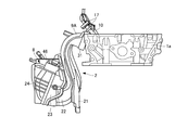
- an engine 1 which is an internal combustion engine includes a cylinder head 1a and a cylinder block 1b, and the cylinder head 1a is connected to a resin intake manifold 2.
- An intake manifold 2 mounted on the engine 1 allows outside air introduced from an air duct (not shown) through an intake pipe 3 to a combustion chamber 4 of each cylinder formed in the cylinder block 1b through an intake port formed in the cylinder head 1a. Distributed and introduced.
- an exhaust manifold 5 is connected to the cylinder head 1a.
- the exhaust manifold 5 collectively discharges exhaust gas discharged from the combustion chamber 4 of each cylinder of the engine 1 to the exhaust pipe 6.
- the intake pipe 3 is provided with a throttle valve 7.
- the throttle valve 7 adjusts the amount of intake air introduced into the combustion chamber 4.
- the intake manifold 2 includes a surge tank 8 connected to the intake pipe 3, and an intake branch pipe 9 branched from the surge tank 8 and having a distribution passage communicating with each combustion chamber of the engine 1.
- the number of intake branch pipes 9 corresponding to the number of cylinders of the engine 1 is provided. Since the intake manifold 2 of the present embodiment is applied to a 4-cylinder engine, four intake branch pipes 9 are provided. However, the number of cylinders of the engine 1 is not particularly limited to four cylinders.
- a fuel injection valve 10 is attached to the upper part of the cylinder head 1 a above the intake branch pipe 9.
- the fuel injection valve 10 is configured to inject fuel into the combustion chamber 4 through an intake port formed in the cylinder head 1a.
- the piston 12 reciprocates by the combustion energy at this time, and the reciprocating movement of the piston 12 is converted into the rotational motion of the crankshaft 13 of the engine 1. Further, the engine 1 is provided with an EGR mechanism 14 for reducing the amount of nitrogen oxide (NOx) contained in the exhaust gas.
- the EGR mechanism 14 returns a part of the exhaust gas exhausted to the exhaust pipe 6 to the intake manifold 2.
- the EGR mechanism 14 changes the flow rate of the EGR gas recirculated from the exhaust pipe 6 to the intake manifold 2 by varying the opening degree in the EGR pipe 15 and the EGR pipe 15 connecting the exhaust pipe 6 and the intake manifold 2. And an EGR valve 16 to be adjusted.
- the EGR mechanism 14 recirculates a part of the exhaust of the engine 1 to the intake manifold 2, thereby lowering the combustion temperature of the air-fuel mixture in the combustion chamber 4 to reduce the generation of NOx, and to the exhaust of the engine 1.
- the amount of NOx contained can be reduced.
- the cylinder head 1a is provided with a metal delivery pipe 17. As shown in FIG.
- the delivery pipe 17 extends in the axial direction of the crankshaft 13, that is, in the crankshaft direction, and is installed on one side of the cylinder head 1a above the upper surface of the cylinder head 1a.
- a fuel injection valve 10 provided for each cylinder is connected to the delivery pipe 17.
- the fuel injection valve 10 is installed on the upper surface of the cylinder head 1a so as to be positioned on one side of the cylinder head 1a.
- the fuel injection valve 10 is supplied with fuel from a delivery pipe 17.
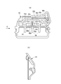
- the engine 1 of the present embodiment is installed vertically so that the axis of the crankshaft 13, that is, the crank axis extends in the front-rear direction of the vehicle 50.
- the intake manifold 2 is installed on one side of the engine 1 so as to be located laterally (laterally) with respect to the longitudinal direction of the vehicle 50.
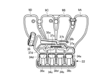
- FIG. 1 a specific configuration of the intake manifold 2 will be described with reference to FIGS. 2, 3, and 5 to 14.
- the intake manifold 2 is divided into a plurality of parts on the side that is close to one side of the engine 1 and the side that is separated from one side of the engine 1. There are provided a plurality of divided bodies joined together.
- the first divided branch pipe 21 is joined to the second divided branch pipe 22 by welding or adhesion.
- the second divided branch pipe 22 is joined to the EGR case 23 by welding or adhesion.
- the EGR case 23 is joined to the surge tank case 24 by welding or adhesion.
- the surge tank 8 is constituted by the EGR case 23 and the surge tank case 24, and four intake branches are constituted by the first divided branch pipe 21 and the second divided branch pipe 22. Tubes 9A to 9D are formed.
- the first divided branch pipe 21 constitutes one of the intake branch pipes 9A to 9D.
- a flange portion 31 connected to the cylinder head 1a is formed at the distal end portion of the first divided branch pipe 21.
- the flange portion 31 is formed with openings 31a to 31d communicating with the intake port of the cylinder head 1a.
- the flange portion 31 is formed with a plurality of bolt insertion holes 31A.
- a bolt (not shown) is inserted into the bolt insertion hole 31A and the bolt is screwed into the cylinder head 1a, whereby the flange portion 31 is fastened to the cylinder head 1a.
- the second divided branch pipe 22 constitutes the other of the intake branch pipes 9A to 9D.
- a plurality of openings 34 a to 34 d are formed in the lower part of the second divided branch pipe 22.
- the openings 34a to 34d are the inner peripheral portions of the intake branch pipes 9A to 9D constituted by the first divided branch pipe 21 and the second divided branch pipe 22, that is, the distribution passage 35a of the intake branch pipes 9A to 9D. To 35d.
- the distribution passages 35a to 35d are formed by one surface of the first divided branch pipe 21 and one surface of the second divided branch pipe 22, and are opened.
- the portions 34a to 34d communicate with the distribution passages 35a to 35d.
- an EGR gas introduction part 36 is provided on the other surface of the second divided branch pipe 22.
- the EGR gas introduction unit 36 is connected to the EGR pipe 15 so that EGR gas is introduced from the EGR pipe 15.
- communication holes 37 a to 37 d are formed in the second divided branch pipe 22.
- the communication holes 37a to 37d communicate with the distribution passages 35a to 35d, respectively.
- the other surface of the second divided branch pipe 22 has a main passage portion 38a communicating with the EGR gas introduction portion 36 and a distribution passage portion 38b branched from the main passage portion 38a and continuing to the communication holes 37a to 37d, respectively.
- To 38e are formed.
- a main passage portion 40a communicating with the EGR gas introduction portion 36 and distribution passage portions 40b to 40e branched from the main passage portion 40a are formed on one surface of the EGR case 23. .
- the main passage 42a is defined by the main passage portion 38a and the main passage portion 40a in the inner peripheral portion of the second divided branch pipe 22 and the EGR case 23, and the distribution passage portions 38b to 38e and the distribution passage portions 40b to 40e.
- the distribution passages 42b to 42e are defined (the signs of the main passage 42a and the distribution passages 42b to 42e are attached only to FIG. 11 (a)).
- a plurality of ribs 44 are formed below the distribution passage portions 40b to 40e of the EGR case 23. As shown in FIG. The rib 44 is located between the openings 31a to 31d of the second divided branch pipe 22 adjacent to each other in the second divided branch pipe 22, and serves as a guide for the intake air introduced into the openings 31a to 31d. It has a function.
- the surge tank case 24 is provided with an intake air inlet 46.
- the intake air inlet 46 is connected to the intake pipe 3 so that intake air is introduced through the intake pipe 3.
- an intake passage 47 is defined between the EGR case 23 and the other surface of the surge tank case 24, through which intake air is introduced from the intake introduction portion 46.
- intake air is introduced into the intake passage 47 from the intake introduction portion 46, the intake air is guided by the ribs 44 of the second divided branch pipe 22 and introduced into the openings 31a to 31d of the second divided branch pipe 22. Is done.
- the intake air introduced into the openings 31a to 31d enters the combustion chamber 4 of the engine 1 through the distribution passages 35a to 35d of the intake branch pipe 9 constituted by the first divided branch pipe 21 and the second divided branch pipe 22. Led.
- the surge tank case 24 is provided with a purge gas introduction part 51, and evaporated fuel evaporated from a fuel tank (not shown) is introduced into the intake passage 47 through the purge gas introduction part 51. This evaporated fuel is introduced into the combustion chamber 4 of the engine 1 together with the intake air from the intake passage 47 through the distribution passages 35a to 35d.
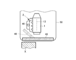
- the flange portion 31 of the first divided branch pipe 21 has a contact surface 32 a on one side surface.
- the contact surface 32a is in contact with one side surface of the cylinder head 1a.
- the flange portion 31 is fastened to the cylinder head 1 a so as to face the fuel injection valve 10 below the fuel injection valve 10.
- the flange part 31 has the joint surface 32b which comprises a 1st joint surface in the other side surface.
- the joint surface 32b is formed in a straight line.
- a joint portion 33 is formed at the distal end portion of the second divided branch pipe 22, and a joint surface constituting a second joint surface is formed on one side surface of the joint portion 33.
- 33a is formed.
- the joint surface 33 a is formed in a straight line shape, and the joint surface 33 a of the joint portion 33 is joined to the joint surface 32 b of the flange portion 31.
- the joint line 32 b of the flange portion 31 and the extension line L of the joint surface 33 a of the joint portion 33 are set at positions avoiding the fuel injection valve 10. That is, in the intake manifold 2 of the present embodiment, the joint surface 32b and the joint surface are arranged such that the extension line L between the joint surface 32b of the flange portion 31 and the joint surface 33a of the joint portion 33 faces the position away from the fuel injection valve 10.
- the part 33 is joined and attached to the cylinder head 1a.
- the extension line L is specifically an extension line of the joint surface formed between both surfaces when the joint surface 32b and the joint surface 33a are joined, and the extension of the joint surface 33a. A line extending outward in the direction.
- the fuel injection valve 10 is inclined at a predetermined angle with respect to the upper surface of the cylinder head 1a so as to smoothly supply fuel from the fuel injection valve 10 to the combustion chamber 4 via the intake port. is set up. For this reason, a space a is defined between the cylinder head 1 a and the flange portion 31.
- the joint portion 33 is formed such that the length A in the extending direction of the joint surface 33 a is longer than the maximum separation distance B between the fuel injection valve 10 and the flange portion 31. For this reason, the joint portion 33 is prevented from entering the space a between the fuel injection valve 10 and the flange portion 31.
- the engine 1 is installed vertically so that the crank axis extends in the front-rear direction of the vehicle 50, and the intake manifold 2 is lateral (lateral) with respect to the front-rear direction of the vehicle 50. It is installed on one side of the engine 1 so as to be located on the side.
- a bumper reinforcement 48 that constitutes a part of the chassis is provided in front of the vehicle 50. Accordingly, when a so-called offset collision occurs in which one of the left and right directions of the vehicle 50 collides with the object X, the bumper reinforcement 48 is deformed as indicated by a broken line and collides with the intake manifold 2.
- the intake manifold 2 When the impact force that the bumper reinforcement 48 pushes up the intake manifold 2 acts on the intake manifold 2 depending on the situation at the time of the vehicle collision, the intake manifold 2 is deformed upward as a whole.
- the joint surface 32b and the joint portion 33 are arranged such that the extension line L between the joint surface 32b of the flange portion 31 and the joint surface 33a of the joint portion 33 faces the position away from the fuel injection valve 10. Therefore, when the joint surface 33a of the joint portion 33 slides upward with respect to the joint surface 32b of the flange portion 31, it is possible to suppress the joint portion 33 from directly colliding with the fuel injection valve 10. it can.
- the metal delivery pipe 17 is provided so as to extend in the crankshaft direction of the engine 1, whereas the fuel injection valve 10 has a cylindrical shape provided for each cylinder of the engine 1.
- the strength is lower than that of the delivery pipe 17. For this reason, when the joint portion 33 collides with the fuel injection valve 10, a large impact may be applied to the fuel injection valve 10.
- the joint portion 33 can be prevented from directly colliding with the fuel injection valve 10, it is possible to suppress the intake manifold 2 from interfering with the fuel injection valve 10.
- the joint portion 33 may enter the space a between the cylinder head 1 a and the flange portion 31 depending on the deformation behavior of the intake manifold 2.
- the joint portion 33 is formed so that the length A in the extending direction of the joint surface 33 a is longer than the maximum separation distance B between the fuel injection valve 10 and the flange portion 31.
- the joining portion 33 can be prevented from entering the space a between the fuel injection valve 10 and the flange portion 31.
- the joint surface 32b of the flange portion 31 and the joint surface 33a of the joint portion 33 are formed in a straight line, the behavior of the intake manifold 2 at the time of a vehicle collision is different from the flange portion 31.
- the joint portion 33 slides upward, the joint portion 33 can be prevented from directly colliding with the fuel injection valve 10.
- the flange portion 31 is connected to the cylinder head 1a so as to face the fuel injection valve 10 below the fuel injection valve 10, so that the position where the fuel injection valve 10 is avoided.
- the flange portion 31 and the joint portion 33 can be joined such that the extension line L between the joint surface 32b and the joint surface 33a faces. For this reason, it is possible to prevent the joint portion 33 from directly colliding with the fuel injection valve 10 when the joint portion 33 slides upward with respect to the flange portion 31 due to the behavior of the intake manifold 2 at the time of a vehicle collision.
- the intake manifold 2 of the present embodiment is divided into a first divided branch pipe 21, a second divided branch pipe 22, an EGR case 23, and a surge tank case 24, but is not limited to this. Absent.
- it may be constituted by an intake manifold provided with a surge tank and an intake branch pipe having no EGR passage. That is, any type of intake manifold may be used as long as it has an intake branch pipe in which at least the first divided branch pipe and the second divided branch pipe are divided.
- the intake manifold according to the present invention has an effect that the intake manifold can be prevented from interfering with the fuel injection valve at the time of a vehicle collision, and is connected to the internal combustion engine, and is connected to each cylinder of the internal combustion engine. This is useful as an intake manifold for introducing intake air.
Landscapes
- Engineering & Computer Science (AREA)
- Chemical & Material Sciences (AREA)
- Combustion & Propulsion (AREA)
- Mechanical Engineering (AREA)
- General Engineering & Computer Science (AREA)
- Fuel-Injection Apparatus (AREA)
Abstract
本発明は、車両衝突時に吸気マニホールドが燃料噴射弁に干渉するのを抑制することができる吸気マニホールドを提供することを課題とする。吸気マニホールド(2)は、燃料噴射弁(10)を避けた位置にフランジ部(31)の接合面(32b)および接合部(33)の接合面(33a)との延長線Lが向くように接合面(32b)および接合部(33)が接合されている。また、吸気マニホールド(2)は、接合面(33a)の延在方向長さAが燃料噴射弁(10)とフランジ部(31)との最大離隔距離Bよりも長くなるように接合部(33)が形成されている。
Description
本発明は、吸気マニホールドに関し、特に、内燃機関に接続され、内燃機関の各気筒に吸入空気を導入する吸気マニホールドに関する。
車両に搭載される内燃機関には、サージタンクと内燃機関の各気筒に吸入空気を分配する吸気枝管とを備えた吸気マニホールドが取付けられている。この吸気マニホールドは、複雑な形状であることから接合面を介して接合される複数の分割体から構成されている。
また、内燃機関には燃料噴射弁が取付けられており、車両衝突時に吸気マニホールドが燃料噴射弁に衝突するのを抑制する必要がある。
吸気マニホールドが燃料系部品に衝突するのを抑制するものとしては、吸気マニホールドのインテークマニホールドアッパおよびインテークホールドミドルの溶着位置とデリバリパイプとの距離を所定距離a以上確保したものがある(例えば、特許文献1参照)。この吸気マニホールドは、車両衝突時に吸気マニホールドが損傷したときに、吸気マニホールドの破片によりデリバリパイプが損傷するのを防止することができる。
しかしながら、このような従来の吸気マニホールドにあっては、車両衝突時にインテークマニホールドアッパがインテークホールドミドルに対してデリバリパイプ側にスライドした場合に、インテークマニホールドアッパの先端がデリバリパイプに接続される燃料噴射弁と内燃機関との間の空間に進入してしまう。
一般に、デリバリパイプは、内燃機関のクランク軸方向に延在して設けられているのに対して、燃料噴射弁は、内燃機関の気筒毎に設けられた筒状形状をしており、デリバリパイプに比べて強度が低い。このため、インテークマニホールドアッパの先端がデリバリパイプに接続される燃料噴射弁の下方の空間に進入してしまうと、インテークマニホールドアッパの先端が燃料噴射弁に干渉してしまうおそれがある。
本発明は、上述のような従来の問題を解決するためになされたもので、車両衝突時に吸気マニホールドが燃料噴射弁に干渉するのを抑制することができる吸気マニホールドを提供することを目的とする。
本発明に係る吸気マニホールドは、上記目的を達成するため、シリンダヘッドの上面に前記シリンダヘッドの一側面側に位置するように燃料噴射弁が設置された内燃機関に搭載され、前記燃料噴射弁に対向するようにして前記シリンダヘッドの一側面に接続された吸気マニホールドであって、前記シリンダヘッドの吸気ポートに吸入空気を導入する樹脂製の複数の吸気枝管を有し、前記吸気枝管が第1の分割枝管と前記第1の分割枝管に接合される第2の分割枝管とに分割して構成され、前記第1の分割枝管の先端部に、一側面に前記シリンダヘッドに当接する当接面を有するとともに他側面に第1の接合面を有し、前記シリンダヘッドに取付けられるフランジ部が形成され、前記第2の分割枝管の先端部に、前記第1の接合面に接合される第2の接合面を有する接合部が形成され、前記燃料噴射弁を避けた位置に前記第1の接合面と前記第2の接合面との延長線が向くように前記フランジ部と前記接合部とが前記シリンダヘッドに取付けられ、前記接合部は、前記第2の接合面の延在方向の長さが前記燃料噴射弁と前記フランジ部の最大離隔距離よりも長くなるものから構成されている。
この吸気マニホールドは、燃料噴射弁を避けた位置に第1の分割枝管のフランジ部の第1の接合面と第2の分割枝管の接合部の第2の接合面との延長線が向くようにフランジ部と接合部とがシリンダヘッドに取付けられるので、車両衝突時の吸気マニホールドの挙動によって第1の分割枝管のフランジ部に対して第2の分割枝管の接合部が上方にスライドしたときに、第2の分割枝管の接合部が燃料噴射弁に直接衝突しない。
また、接合部の第2の接合面の延在方向長さが燃料噴射弁とフランジ部の最大離隔距離よりも長くなるよう接合部が形成されるので、第2の分割枝管の接合部が第1の分割枝管のフランジ部と燃料噴射弁の間の空間に進入するのを防止することができる。このため、第2の分割枝管の接合部が燃料噴射弁に衝突するのを確実に抑制することができる。この結果、吸気マニホールドが燃料噴射弁に干渉するのを抑制することができる。
好ましくは、前記第1の接合面および前記第2の接合面は、直線状に形成されるものから構成されている。
この吸気マニホールドは、第1の接合面および第2の接合面が直線状に形成されるので、車両衝突時の吸気マニホールドの挙動によって第1の分割枝管のフランジ部に対して第2の分割枝管の接合部が上方にスライドしたときに、第2の分割枝管の接合部が燃料噴射弁に直接衝突するのを抑制することができる。
より好ましくは、前記フランジ部が、前記燃料噴射弁の下方で前記燃料噴射弁に対向するように前記シリンダヘッドに接続されるものから構成されている。
この吸気マニホールドは、フランジ部が、燃料噴射弁の下方で燃料噴射弁に対向するようにシリンダヘッドに接続されるので、燃料噴射弁を避けた位置に第1の接合面と第2の接合面との延長線が向くようにフランジ部と接合部とを接合することができる。このため、車両衝突時の吸気マニホールドの挙動によって第1の分割枝管のフランジ部に対して第2の分割枝管の接合部が上方にスライドしたときに、第2の分割枝管の接合部が燃料噴射弁に直接衝突するのを抑制することができる。
本発明によれば、車両衝突時に吸気マニホールドが燃料噴射弁に干渉するのを抑制することができる吸気マニホールドを提供することができる。
以下、本発明に係る吸気マニホールドの実施の形態について、図面を用いて説明する。
図1~図16は、本発明に係る吸気マニホールドの一実施の形態を示す図である。まず、構成を説明する。
図1において、内燃機関であるエンジン1は、シリンダヘッド1aおよびシリンダブロック1bを備えており、シリンダヘッド1aには樹脂製の吸気マニホールド2に接続されている。
エンジン1に搭載された吸気マニホールド2は、図示しないエアダクトから吸気管3を通して導入された外気をシリンダヘッド1aに形成された吸気ポートを介してシリンダブロック1bに形成された各気筒の燃焼室4に分配して導入するようになっている。
また、シリンダヘッド1aには排気マニホールド5が接続されている。排気マニホールド5は、エンジン1の各気筒の燃焼室4から排出される排気ガスを纏めて排気管6に排出するようになっている。
吸気管3にはスロットルバルブ7が設けられている。スロットルバルブ7は、燃焼室4に導入される吸入空気量を調整するようになっている。また、吸気マニホールド2は、吸気管3に接続されたサージタンク8と、サージタンク8から分岐され、エンジン1の各燃焼室に連通する分配通路を有する吸気枝管9とを備えている。
なお、吸気枝管9は、エンジン1の気筒数に応じた数だけ設けられている。本実施の形態の吸気マニホールド2は、4気筒エンジンに適用されるため、吸気枝管9が4つ設けられている。但し、エンジン1の気筒数は、特に4気筒に限定されるものではない。
吸気枝管9の上方のシリンダヘッド1aの上部には燃料噴射弁10が取付けられている。この燃料噴射弁10は、シリンダヘッド1aに形成された吸気ポートを通して燃焼室4に燃料を噴射するようになっている。
燃料噴射弁10から燃焼室4に燃料が噴射されると、吸気枝管9の分配通路から導入される空気と燃料とからなる混合気が燃焼室4内に充填され、この混合気が各気筒に設けられた点火プラグ11の点火によって燃焼される。
このときの燃焼エネルギによってピストン12が往復移動し、ピストン12の往復移動がエンジン1のクランクシャフト13の回転運動に変換される。また、エンジン1には、排気に含まれる窒素酸化物(NOx)の量を低減させるためのEGR機構14が設けられている。このEGR機構14は、排気管6に排気された排気ガスの一部を吸気マニホールド2に戻すようになっている。
EGR機構14は、排気管6と吸気マニホールド2とを接続するEGR管15と、EGR管15内の開度を可変することにより、排気管6から吸気マニホールド2に還流されるEGRガスの流量を調整するEGRバルブ16とを備えている。
このEGR機構14は、エンジン1の排気の一部を吸気マニホールド2に還流させることで、燃焼室4内での混合気の燃焼温度を低下させてNOxの生成を低減し、エンジン1の排気に含まれるNOxの量を低減させることができる。
図2、図3に示すように、シリンダヘッド1aには金属製のデリバリパイプ17が設けられている。このデリバリパイプ17は、クランクシャフト13の軸線方向、すなわち、クランク軸方向に延在し、シリンダヘッド1aの上面よりも上方においてシリンダヘッド1aの一側面側に設置されている。
また、デリバリパイプ17には気筒毎に設けられた燃料噴射弁10が接続されている。この燃料噴射弁10は、シリンダヘッド1aの上面にシリンダヘッド1aの一側面側に位置するようにして設置されている。燃料噴射弁10にはデリバリパイプ17から燃料が供給されるようになっている。
また、図4に示すように、本実施の形態のエンジン1は、クランクシャフト13の軸線、すなわち、クランク軸線が車両50の前後方向に延在するように縦置きに設置されている。吸気マニホールド2は、車両50の前後方向に対して側方(横側)に位置するようにエンジン1の一側面に設置されている。
次に、図2、図3、図5~図14に基づいて吸気マニホールド2の具体的な構成を説明する。
図2、図3、図5、図6において、吸気マニホールド2は、エンジン1の一側面に対して近接する側とエンジン1の一側面に対して離隔する側とにおいて複数に分割され、接合面を介して接合された複数の分割体を備えている。
具体的には、エンジン1の一側面に対して近接する側から離隔する側に向かってそれぞれ樹脂製の第1の分割枝管21、第2の分割枝管22、EGRケース23およびサージタンクケース24に分割されている。
第1の分割枝管21は、第2の分割枝管22に溶着あるいは接着によって接合されている。第2の分割枝管22は、EGRケース23に溶着あるいは接着によって接合されている。また、EGRケース23は、サージタンクケース24に溶着あるいは接着によって接合されている。
また、本実施の形態の吸気マニホールド2は、EGRケース23およびサージタンクケース24によってサージタンク8が構成されており、第1の分割枝管21および第2の分割枝管22によって4つの吸気枝管9A~9Dが構成されている。
図7、図8に示すように、第1の分割枝管21は、吸気枝管9A~9Dの一方を構成している。第1の分割枝管21の先端部にはシリンダヘッド1aに接続されるフランジ部31が形成されている。このフランジ部31にはシリンダヘッド1aの吸気ポートに連通する開口部31a~31dが形成されている。
また、フランジ部31には、複数のボルト挿通孔31Aが形成されている。このボルト挿通孔31Aに図示しないボルトが挿通されてボルトがシリンダヘッド1aに螺合されることにより、フランジ部31がシリンダヘッド1aに締結される。
図9、図10に示すように、第2の分割枝管22は、吸気枝管9A~9Dの他方を構成している。第2の分割枝管22の下部には複数の開口部34a~34dが形成されている。この開口部34a~34dは、第1の分割枝管21と第2の分割枝管22によって構成される吸気枝管9A~9Dの内周部、すなわち、吸気枝管9A~9Dの分配通路35a~35dに連通している。
具体的には、図8、図9に示すように、分配通路35a~35dは、第1の分割枝管21の一方の面および第2の分割枝管22の一方の面によって形成され、開口部34a~34dがこの分配通路35a~35dに連通している。
また、図10に示すように、第2の分割枝管22の他方の面にはEGRガス導入部36が設けられている。このEGRガス導入部36は、EGR管15に接続され、EGR管15からEGRガスが導入されるようになっている。
また、第2の分割枝管22には連通孔37a~37dが形成されている。この連通孔37a~37dは、分配通路35a~35dにそれぞれ連通している。また、第2の分割枝管22の他方の面にはEGRガス導入部36に連通するメイン通路部38aと、メイン通路部38aから分岐され、それぞれ連通孔37a~37dに連続する分配通路部38b~38eが形成されている。
図11に示すように、EGRケース23の一方の面にはEGRガス導入部36に連通するメイン通路部40aと、メイン通路部40aから分岐された分配通路部40b~40eとが形成されている。
したがって、第2の分割枝管22とEGRケース23の内周部にはメイン通路部38aおよびメイン通路部40aによってメイン通路42aが画成され、分配通路部38b~38eおよび分配通路部40b~40eによって分配通路42b~42eが画成される(メイン通路42aおよび分配通路42b~42eの符号は、図11(a)のみに付す)。
図11、図12に示すように、EGRケース23の分配通路部40b~40eの下方には複数のリブ44が形成されている。このリブ44は、第2の分割枝管22において隣接する第2の分割枝管22の開口部31a~31dの間に位置しており、開口部31a~31dに導入される吸入空気のガイドの機能を有する。
図13、図14に示すように、サージタンクケース24には吸気導入部46が設けられている。この吸気導入部46は、吸気管3に接続され、吸気管3を通して吸入空気が導入されるようになっている。
このサージタンクケース24は、EGRケース23とサージタンクケース24の他方の面との間に吸気導入部46から吸入空気が導入される吸気通路47が画成されている。吸気導入部46から吸気通路47に吸入空気が導入されると、この吸入空気が第2の分割枝管22のリブ44に案内されて第2の分割枝管22の開口部31a~31dに導入される。開口部31a~31dに導入される吸入空気は、第1の分割枝管21および第2の分割枝管22によって構成される吸気枝管9の分配通路35a~35dを通してエンジン1の燃焼室4に導かれる。
なお、サージタンクケース24にはパージガス導入部51が設けられており、吸気通路47にパージガス導入部51を通して図示しない燃料タンクから蒸発した蒸発燃料が導入される。この蒸発燃料は、吸気通路47から分配通路35a~35dを通して吸入空気と共にエンジン1の燃焼室4に導入される。
一方、図7、図15に示すように、第1の分割枝管21のフランジ部31は、一側面に当接面32aを有している。この当接面32aは、シリンダヘッド1aの一側面に当接するようになっている。また、フランジ部31は、燃料噴射弁10の下方で燃料噴射弁10に対向するようにシリンダヘッド1aに締結されている。
フランジ部31は、他側面に第1の接合面を構成する接合面32bを有している。この接合面32bは、直線状に形成されている。
図9、図15に示すように、第2の分割枝管22の先端部には接合部33が形成されており、この接合部33の一側面には第2の接合面を構成する接合面33aが形成されている。この接合面33aは、直線状に形成されており、接合部33の接合面33aは、フランジ部31の接合面32bに接合される。
図15に示すように、フランジ部31の接合面32bおよび接合部33の接合面33aの延長線Lは、燃料噴射弁10を避けた位置に設定されている。すなわち、本実施の形態の吸気マニホールド2は、燃料噴射弁10を避けた位置にフランジ部31の接合面32bおよび接合部33の接合面33aとの延長線Lが向くように接合面32bおよび接合部33が接合されてシリンダヘッド1aに取付けられている。ここで、上記延長線Lとは、具体的には接合面32bと接合面33aとが接合された際に両面の間に形成される接合面の延長線であって、接合面33aの延在方向の外側に向かって延長された線である。
また、燃料噴射弁10は、燃料噴射弁10から吸気ポートを介して燃焼室4に燃料を円滑に供給するために、シリンダヘッド1aの上面に対して所定角度傾斜してシリンダヘッド1aの上面に設置されている。このため、シリンダヘッド1aとフランジ部31の間には空間aが画成される。
また、接合部33は、接合面33aの延在方向長さAが燃料噴射弁10とフランジ部31との最大離隔距離Bよりも長くなるように形成されている。このため、接合部33は、燃料噴射弁10とフランジ部31との間の空間aに進入しないようになっている。
次に、作用を説明する。
図4に示すように、エンジン1は、クランク軸線が車両50の前後方向に延在するように縦置きに設置されており、吸気マニホールド2は、車両50の前後方向に対して側方(横側)に位置するようにエンジン1の一側面に設置されている。
車両50の前方にはシャーシの一部を構成するバンパリーンホースメント48が設けられている。したがって、車両50の左右方向の一方が対象物Xに対して衝突する、所謂、オフセット衝突が発生すると、バンパリーンホースメント48が破線で示すように変形して吸気マニホールド2に衝突する。
車両衝突時の状況により、バンパリーンホースメント48が吸気マニホールド2を上方に押し上げるような衝撃力が吸気マニホールド2に作用した場合には、吸気マニホールド2が全体的に上方に変形する。
第1の分割枝管21のフランジ部31は、ボルトによってシリンダヘッド1aに強固に締結されているため、吸気マニホールド2が上方に変形すると、第2の分割枝管22の接合部33の直線状の接合面33aがフランジ部31の直線状の接合面32bに対して上方にスライドする(図16参照)。
本実施の形態の吸気マニホールド2は、燃料噴射弁10を避けた位置にフランジ部31の接合面32bおよび接合部33の接合面33aとの延長線Lが向くように接合面32bおよび接合部33が接合されているため、接合部33の接合面33aがフランジ部31の接合面32bに対して上方にスライドしたときに、接合部33が燃料噴射弁10に直接衝突するのを抑制することができる。
一般に、金属製のデリバリパイプ17は、エンジン1のクランク軸方向に延在して設けられているのに対して、燃料噴射弁10は、エンジン1の気筒毎に設けられた筒状形状をしており、デリバリパイプ17に比べて強度が低い。このため、接合部33が燃料噴射弁10に衝突すると、燃料噴射弁10に大きな衝撃が加えられてしまうおそれがある。
本実施の形態では、接合部33が燃料噴射弁10に直接衝突するのを抑制することができるので、吸気マニホールド2が燃料噴射弁10に干渉するのを抑制することができる。
また、接合部33が上方に移動したときに吸気マニホールド2の変形の挙動によっては、接合部33がシリンダヘッド1aとフランジ部31の間の空間aに進入する可能性がある。
本実施の形態の吸気マニホールド2は、接合面33aの延在方向長さAが燃料噴射弁10とフランジ部31との最大離隔距離Bよりも長くなるように接合部33が形成されているため、接合部33が燃料噴射弁10とフランジ部31との間の空間aに進入するのを防止することができる。
このため、接合部33が燃料噴射弁10に衝突するのをより確実に抑制することができ、吸気マニホールド2が燃料噴射弁10に干渉するのを確実に抑制することができる。
また、本実施の形態の吸気マニホールド2は、フランジ部31の接合面32bおよび接合部33の接合面33aを直線状に形成したので、車両衝突時の吸気マニホールド2の挙動によってフランジ部31に対して接合部33が上方にスライドしたときに、接合部33が燃料噴射弁10に直接衝突するのを抑制することができる。
また、本実施の形態の吸気マニホールド2は、フランジ部31が、燃料噴射弁10の下方で燃料噴射弁10に対向するようにシリンダヘッド1aに接続されるので、燃料噴射弁10を避けた位置に接合面32bと接合面33aとの延長線Lが向くようにフランジ部31と接合部33とを接合することができる。このため、車両衝突時の吸気マニホールド2の挙動によってフランジ部31に対して接合部33が上方にスライドしたときに、接合部33が燃料噴射弁10に直接衝突するのを抑制することができる。
また、本実施の形態の吸気マニホールド2は、第1の分割枝管21、第2の分割枝管22、EGRケース23およびサージタンクケース24に分割されているが、これに限定されるものではない。
例えば、EGR通路が存在しないサージタンクと吸気枝管とを備えた吸気マニホールドから構成されてもよい。すなわち、少なくとも第1の分割枝管および第2の分割枝管が分割された吸気枝管を有する吸気マニホールドであれば、どのような形態の吸気マニホールドでもよい。
以上のように、本発明に係る吸気マニホールドは、車両衝突時に吸気マニホールドが燃料噴射弁に干渉するのを抑制することができるという効果を有し、内燃機関に接続され、内燃機関の各気筒に吸入空気を導入する吸気マニホールド等として有用である。
1...エンジン、1a...シリンダヘッド、2...吸気マニホールド、9,9A~9D...吸気枝管、10...燃料噴射弁、21...第1の分割枝管、22...第2の分割枝管、31...フランジ部、32a...当接面、32b...接合面、33...接合部、33a...接合面
Claims (3)
- シリンダヘッドの上面に前記シリンダヘッドの一側面側に位置するように燃料噴射弁が設置された内燃機関に搭載され、前記燃料噴射弁に対向するようにして前記シリンダヘッドの一側面に接続された吸気マニホールドであって、
前記シリンダヘッドの吸気ポートに吸入空気を導入する樹脂製の複数の吸気枝管を有し、前記吸気枝管が第1の分割枝管と前記第1の分割枝管に接合される第2の分割枝管とに分割して構成され、
前記第1の分割枝管の先端部に、一側面に前記シリンダヘッドに当接する当接面を有するとともに他側面に第1の接合面を有し、前記シリンダヘッドに取付けられるフランジ部が形成され、
前記第2の分割枝管の先端部に、前記第1の接合面に接合される第2の接合面を有する接合部が形成され、
前記燃料噴射弁を避けた位置に前記第1の接合面と前記第2の接合面との延長線が向くように前記フランジ部と前記接合部とが前記シリンダヘッドに取付けられ、
前記接合部は、前記第2の接合面の延在方向の長さが前記燃料噴射弁と前記フランジ部の最大離隔距離よりも長くなるように形成されることを特徴とする吸気マニホールド。 - 前記第1の接合面および前記第2の接合面は、直線状に形成されることを特徴とする請求項1に記載の吸気マニホールド。
- 前記フランジ部が、前記燃料噴射弁の下方で前記燃料噴射弁に対向するように前記シリンダヘッドに接続されることを特徴とする請求項1または請求項2に記載の吸気マニホールド。
Priority Applications (3)
| Application Number | Priority Date | Filing Date | Title |
|---|---|---|---|
| CN201380057698.4A CN104769267B (zh) | 2012-10-31 | 2013-09-02 | 吸气歧管 |
| US14/439,590 US9429115B2 (en) | 2012-10-31 | 2013-09-02 | Intake manifold |
| EP13851353.6A EP2915990B1 (en) | 2012-10-31 | 2013-09-02 | Arrangement of an intake manifold, a cylinder head and fuel injection valves |
Applications Claiming Priority (2)
| Application Number | Priority Date | Filing Date | Title |
|---|---|---|---|
| JP2012240516A JP5870900B2 (ja) | 2012-10-31 | 2012-10-31 | 吸気マニホールド |
| JP2012-240516 | 2012-10-31 |
Publications (1)
| Publication Number | Publication Date |
|---|---|
| WO2014068824A1 true WO2014068824A1 (ja) | 2014-05-08 |
Family
ID=50626782
Family Applications (1)
| Application Number | Title | Priority Date | Filing Date |
|---|---|---|---|
| PCT/JP2013/005170 WO2014068824A1 (ja) | 2012-10-31 | 2013-09-02 | 吸気マニホールド |
Country Status (5)
| Country | Link |
|---|---|
| US (1) | US9429115B2 (ja) |
| EP (1) | EP2915990B1 (ja) |
| JP (1) | JP5870900B2 (ja) |
| CN (1) | CN104769267B (ja) |
| WO (1) | WO2014068824A1 (ja) |
Families Citing this family (3)
| Publication number | Priority date | Publication date | Assignee | Title |
|---|---|---|---|---|
| JP6436179B2 (ja) * | 2017-03-22 | 2018-12-12 | マツダ株式会社 | エンジン |
| JP6766733B2 (ja) | 2017-04-03 | 2020-10-14 | アイシン精機株式会社 | 吸気装置 |
| JP2019127881A (ja) * | 2018-01-24 | 2019-08-01 | トヨタ自動車株式会社 | 内燃機関のインテークマニホールド |
Citations (6)
| Publication number | Priority date | Publication date | Assignee | Title |
|---|---|---|---|---|
| JPH0673368U (ja) * | 1993-03-26 | 1994-10-18 | 株式会社土屋製作所 | 合成樹脂製コレクタ |
| JPH08246968A (ja) * | 1995-03-13 | 1996-09-24 | Toyota Motor Corp | 吸気マニホールド |
| JP2002070673A (ja) * | 2000-08-31 | 2002-03-08 | Keihin Corp | 車両用吸気マニホールドおよびその製造方法 |
| JP2003120467A (ja) * | 2001-10-19 | 2003-04-23 | Nissan Motor Co Ltd | 内燃機関の吸気装置 |
| JP2010234567A (ja) | 2009-03-30 | 2010-10-21 | Toppan Printing Co Ltd | 針状体製造方法および針状体 |
| JP2012197702A (ja) * | 2011-03-18 | 2012-10-18 | Toyota Motor Corp | 吸気マニホールド |
Family Cites Families (12)
| Publication number | Priority date | Publication date | Assignee | Title |
|---|---|---|---|---|
| KR100331454B1 (ko) * | 1998-09-01 | 2002-04-09 | 신구 이이치 | 다기통 내연기관에 있어서의 관성과급식 흡기매니폴드의 구조및 이 흡기매니폴드에 있어서의 브랜치파이프의 접합방법 |
| JP2001342918A (ja) * | 2000-05-31 | 2001-12-14 | Suzuki Motor Corp | 船外機のインテークマニフォールド |
| JP2002070672A (ja) * | 2000-08-31 | 2002-03-08 | Keihin Corp | 車両用吸気マニホールドおよびその製造方法 |
| DE10163816B4 (de) * | 2001-12-22 | 2013-05-29 | Mann + Hummel Gmbh | Ansaugvorrichtung |
| US6988478B2 (en) * | 2003-04-09 | 2006-01-24 | Aisan Kogyo Kabushiki Kaisha | Resin intake manifold |
| JP2006125227A (ja) * | 2004-10-27 | 2006-05-18 | Toyota Motor Corp | 合成樹脂製吸気マニホールドの溶着構造 |
| JP2006291915A (ja) * | 2005-04-14 | 2006-10-26 | Mazda Motor Corp | 車両用エンジンの吸気装置 |
| JP4896822B2 (ja) * | 2007-05-30 | 2012-03-14 | 本田技研工業株式会社 | 内燃機関の吸気マニホルド |
| JP2009013901A (ja) * | 2007-07-05 | 2009-01-22 | Toyota Motor Corp | 多気筒内燃機関の吸気装置 |
| US7451732B1 (en) * | 2008-01-30 | 2008-11-18 | Mann & Hummel Gmbh | Multi-shell air intake manifold with passage for map sensor and method of producing same |
| JP4483965B2 (ja) * | 2008-03-27 | 2010-06-16 | 株式会社デンソー | インテークマニホールド |
| JP5883304B2 (ja) * | 2012-02-07 | 2016-03-15 | 株式会社Roki | インテークマニホールド |
-
2012
- 2012-10-31 JP JP2012240516A patent/JP5870900B2/ja not_active Expired - Fee Related
-
2013
- 2013-09-02 WO PCT/JP2013/005170 patent/WO2014068824A1/ja active Application Filing
- 2013-09-02 US US14/439,590 patent/US9429115B2/en not_active Expired - Fee Related
- 2013-09-02 CN CN201380057698.4A patent/CN104769267B/zh not_active Expired - Fee Related
- 2013-09-02 EP EP13851353.6A patent/EP2915990B1/en not_active Not-in-force
Patent Citations (6)
| Publication number | Priority date | Publication date | Assignee | Title |
|---|---|---|---|---|
| JPH0673368U (ja) * | 1993-03-26 | 1994-10-18 | 株式会社土屋製作所 | 合成樹脂製コレクタ |
| JPH08246968A (ja) * | 1995-03-13 | 1996-09-24 | Toyota Motor Corp | 吸気マニホールド |
| JP2002070673A (ja) * | 2000-08-31 | 2002-03-08 | Keihin Corp | 車両用吸気マニホールドおよびその製造方法 |
| JP2003120467A (ja) * | 2001-10-19 | 2003-04-23 | Nissan Motor Co Ltd | 内燃機関の吸気装置 |
| JP2010234567A (ja) | 2009-03-30 | 2010-10-21 | Toppan Printing Co Ltd | 針状体製造方法および針状体 |
| JP2012197702A (ja) * | 2011-03-18 | 2012-10-18 | Toyota Motor Corp | 吸気マニホールド |
Also Published As
| Publication number | Publication date |
|---|---|
| JP5870900B2 (ja) | 2016-03-01 |
| EP2915990A4 (en) | 2015-11-11 |
| JP2014088853A (ja) | 2014-05-15 |
| US20150285196A1 (en) | 2015-10-08 |
| EP2915990A1 (en) | 2015-09-09 |
| CN104769267A (zh) | 2015-07-08 |
| EP2915990B1 (en) | 2018-03-21 |
| CN104769267B (zh) | 2017-04-26 |
| US9429115B2 (en) | 2016-08-30 |
Similar Documents
| Publication | Publication Date | Title |
|---|---|---|
| EP2599989B1 (en) | Air-intake device | |
| WO2014068824A1 (ja) | 吸気マニホールド | |
| EP1777403A1 (en) | Direct injection engine | |
| US6526933B2 (en) | Multi-cylinder internal combustion engine | |
| JP2014088854A (ja) | 吸気マニホールド | |
| JP4992992B2 (ja) | 燃料供給系部品の配置構造 | |
| US8051837B2 (en) | Intake manifold for vehicle and intake system including the same | |
| WO2014068825A1 (ja) | 吸気マニホールド | |
| US6928978B2 (en) | In-cylinder direct-injection engine and cylinder head | |
| US11530672B2 (en) | Internal combustion engine | |
| JP7211216B2 (ja) | エンジンの燃料供給装置 | |
| US9810173B2 (en) | Engine assembly | |
| CN1244753C (zh) | 带有喷油阀的内燃机 | |
| CN107575298B (zh) | 具有布置在汽缸筒中的喷射装置的内燃发动机及其操作方法 | |
| US6634337B2 (en) | Structure of arranging fuel injection valve of engine | |
| US20050126530A1 (en) | Engine air induction arrangement and method | |
| US11035329B2 (en) | Air intake apparatus | |
| JP7136673B2 (ja) | インテークマニホールド | |
| JP5067202B2 (ja) | 筒内直接噴射式火花点火エンジン | |
| JP2017187004A (ja) | 燃料配管の保護部材 | |
| JP2007146818A (ja) | 内燃機関の吸気管構造 | |
| JP2021028488A (ja) | エンジン部品の取付構造 | |
| JP2017166425A (ja) | 燃料配管の保護部材 | |
| JP2010116834A (ja) | 内燃機関の燃料噴射装置 | |
| GB2560743A (en) | Intake manifold |
Legal Events
| Date | Code | Title | Description |
|---|---|---|---|
| 121 | Ep: the epo has been informed by wipo that ep was designated in this application |
Ref document number: 13851353 Country of ref document: EP Kind code of ref document: A1 |
|
| WWE | Wipo information: entry into national phase |
Ref document number: 14439590 Country of ref document: US |
|
| NENP | Non-entry into the national phase |
Ref country code: DE |
|
| WWE | Wipo information: entry into national phase |
Ref document number: 2013851353 Country of ref document: EP |