WO2014065504A1 - 환자 간호용 이승로봇 - Google Patents
환자 간호용 이승로봇 Download PDFInfo
- Publication number
- WO2014065504A1 WO2014065504A1 PCT/KR2013/008023 KR2013008023W WO2014065504A1 WO 2014065504 A1 WO2014065504 A1 WO 2014065504A1 KR 2013008023 W KR2013008023 W KR 2013008023W WO 2014065504 A1 WO2014065504 A1 WO 2014065504A1
- Authority
- WO
- WIPO (PCT)
- Prior art keywords
- clamp
- patient
- support
- robot
- frame
- Prior art date
- Legal status (The legal status is an assumption and is not a legal conclusion. Google has not performed a legal analysis and makes no representation as to the accuracy of the status listed.)
- Ceased
Links
Images




Classifications
-
- A—HUMAN NECESSITIES
- A61—MEDICAL OR VETERINARY SCIENCE; HYGIENE
- A61G—TRANSPORT, PERSONAL CONVEYANCES, OR ACCOMMODATION SPECIALLY ADAPTED FOR PATIENTS OR DISABLED PERSONS; OPERATING TABLES OR CHAIRS; CHAIRS FOR DENTISTRY; FUNERAL DEVICES
- A61G12/00—Accommodation for nursing, e.g. in hospitals, not covered by groups A61G1/00 - A61G11/00, e.g. trolleys for transport of medicaments or food; Prescription lists
-
- A—HUMAN NECESSITIES
- A61—MEDICAL OR VETERINARY SCIENCE; HYGIENE
- A61G—TRANSPORT, PERSONAL CONVEYANCES, OR ACCOMMODATION SPECIALLY ADAPTED FOR PATIENTS OR DISABLED PERSONS; OPERATING TABLES OR CHAIRS; CHAIRS FOR DENTISTRY; FUNERAL DEVICES
- A61G7/00—Beds specially adapted for nursing; Devices for lifting patients or disabled persons
- A61G7/10—Devices for lifting patients or disabled persons, e.g. special adaptations of hoists thereto
- A61G7/1013—Lifting of patients by
- A61G7/1019—Vertical extending columns or mechanisms
-
- A—HUMAN NECESSITIES
- A61—MEDICAL OR VETERINARY SCIENCE; HYGIENE
- A61G—TRANSPORT, PERSONAL CONVEYANCES, OR ACCOMMODATION SPECIALLY ADAPTED FOR PATIENTS OR DISABLED PERSONS; OPERATING TABLES OR CHAIRS; CHAIRS FOR DENTISTRY; FUNERAL DEVICES
- A61G5/00—Chairs or personal conveyances specially adapted for patients or disabled persons, e.g. wheelchairs
- A61G5/10—Parts, details or accessories
- A61G5/14—Standing-up or sitting-down aids
-
- A—HUMAN NECESSITIES
- A61—MEDICAL OR VETERINARY SCIENCE; HYGIENE
- A61G—TRANSPORT, PERSONAL CONVEYANCES, OR ACCOMMODATION SPECIALLY ADAPTED FOR PATIENTS OR DISABLED PERSONS; OPERATING TABLES OR CHAIRS; CHAIRS FOR DENTISTRY; FUNERAL DEVICES
- A61G7/00—Beds specially adapted for nursing; Devices for lifting patients or disabled persons
- A61G7/10—Devices for lifting patients or disabled persons, e.g. special adaptations of hoists thereto
-
- A—HUMAN NECESSITIES
- A61—MEDICAL OR VETERINARY SCIENCE; HYGIENE
- A61G—TRANSPORT, PERSONAL CONVEYANCES, OR ACCOMMODATION SPECIALLY ADAPTED FOR PATIENTS OR DISABLED PERSONS; OPERATING TABLES OR CHAIRS; CHAIRS FOR DENTISTRY; FUNERAL DEVICES
- A61G7/00—Beds specially adapted for nursing; Devices for lifting patients or disabled persons
- A61G7/10—Devices for lifting patients or disabled persons, e.g. special adaptations of hoists thereto
- A61G7/104—Devices carried or supported by
- A61G7/1046—Mobile bases, e.g. having wheels
-
- A—HUMAN NECESSITIES
- A61—MEDICAL OR VETERINARY SCIENCE; HYGIENE
- A61G—TRANSPORT, PERSONAL CONVEYANCES, OR ACCOMMODATION SPECIALLY ADAPTED FOR PATIENTS OR DISABLED PERSONS; OPERATING TABLES OR CHAIRS; CHAIRS FOR DENTISTRY; FUNERAL DEVICES
- A61G7/00—Beds specially adapted for nursing; Devices for lifting patients or disabled persons
- A61G7/10—Devices for lifting patients or disabled persons, e.g. special adaptations of hoists thereto
- A61G7/1049—Attachment, suspending or supporting means for patients
- A61G7/1053—Rigid harnesses
Definitions
- the present invention relates to a patient care robot for nursing, and more particularly, to minimize the stress on the boarding and moving process by allowing the patient to carry out the fast-moving motion and maintain the boarding itself easily in the most comfortable posture.
- the present invention relates to a transfer robot for patient patient care that minimizes mental and physical stress of the caregiver to prevent the patient from being stressed by the caregiver as well as minimizes manufacturing and glass management costs.
- the caregiver should also be kept by the patient at all times and help the patient to be able to support him or her in a wheelchair, and if the caregiver is superior to the patient, the caregiver's body is not strong. If you are older or older, the patient's behavior or mobility cannot be greatly helped, and there is a problem that the physical and mental stress occurs severely during the patient's care.
- the robot In the case of a robot moving horizontally, the robot is similar in shape to a forklift truck, which makes it difficult to use the baggage when the patient or people around him see it. In the case of the manufacturing cost and management cost of the device was very expensive.
- An object of the present invention has been proposed to improve the conventional characteristics as described above, by minimizing the stress in the riding and moving process by allowing the patient to carry out the transfer operation in a quick time and easily maintain the boarding itself in the most comfortable posture
- the present invention has the following configuration to achieve the above object.
- the patient nursing robot of the present invention the body on which the upper body of the subject is leaning; A first clamp rotatably provided at one side of the body to support an upper body of the person being protected; A second clamp provided at a position adjacent to the first clamp to support a lower body of the to-be-guarded body; A support for extending the lower side of the body to adjust the height of the body; It is configured to include; and a transport table connected to the holding post to rotate and move.
- the first clamp is composed of a belt having elasticity, and a hook for detachably connecting the belt to the body.
- the second clamp includes a belt having elasticity and a hook for detachably connecting the belt with respect to the body, wherein the hook moves along a slot formed in the body along the length of the lower body of the protector.
- the body is formed to have a constant inclined surface in close contact with the protector.
- the angle of inclination is between 45 ⁇ 65 ° relative to the imaginary horizontal line
- the second clamp is preferably 40 to 60% of the position away from the knee joint when compared to the length of the thigh of the subject.
- the holding post is the upper case connected to the body, the lower case is inserted into the upper case and connected to the conveying stand, and inserted into the upper case and the lower case, the elevating to connect the body and the conveying table It comprises a cylinder, an operating lever provided in the body to control the lifting cylinder, and a drive unit for operating the lifting cylinder.
- the body is provided with a handle provided with the operating lever.
- the transfer table is composed of a frame provided with wheels, a connecting table for rotatably connecting the support table and the frame, and a support plate disposed between the frame and the connecting table to support the driving unit.
- the wheel is provided with a stopper.
- the connecting rod is provided with a stepper to make the rotation step by step.
- the stepper is a toggle clamp provided between the support of the support and the frame to clamp the support relative to the frame.
- the stepper includes a housing having a space therein, a housing having a space therein, a vertical axis supported by a spring in the housing and vertically moving, and an insertion hole formed at an equal interval along an arc on a cylindrical upper surface of the frame. It is composed of an extension shaft which is inserted and removed by the lifting of the vertical axis in the support so that the support can be rotated about the frame in stages.
- the holding post is a pillar which is installed vertically in the upward direction of the seungseungdae, a bracket fixed to one side of the vertical surface of the pillar, a cylinder that is supported on the bracket so that the lower end rotatably, and one side by the axis of rotation to the pillar It is rotatably supported and the other side is composed of an arm for supporting the body by a stator and a fixed shaft fixed to the arm to rotatably support the cylinder.
- the present invention it is possible to minimize the stress on the boarding and moving process, and to minimize the mental and physical stress of the caregiver during the boarding or moving process by enabling the patient to perform the transfer operation in a fast time and easily maintain the boarding itself in the most comfortable posture
- the caregiver not only prevents the patient from being stressed, but also has the effect of minimizing the manufacturing and glass management costs.
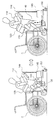
- FIG. 1 is a perspective view showing a first embodiment according to the patient care robot for patient care of the present invention.
- FIG. 2 is an exploded perspective view showing a patient care robot for the patient shown in FIG.
- FIG. 3 is a cross-sectional view showing another embodiment of the stepper shown in FIG.
- 6 to 9 is an operation diagram showing an operating state of the patient care robot for patient care in accordance with the present invention.
- 10 and 11 is a view showing a second embodiment according to the patient care robot for patient care of the present invention.
- first and second may be used to describe various components, but the components should not be limited by the terms. The terms are only used to distinguish one component from another.
- the patient care robot 100 of the present invention is the body 110, the first clamp 120, the second clamp 130, the holding table 140 and the transfer table It comprises 150.
- the body 110 has a shape in which the part to be in close contact is inclined so that the part to be in close contact can be naturally brought up in a state where the part is in close contact.
- the insertion hole 111 having a constant diameter is formed in each middle portion of the left and right sides of the body 110, and the semicircle-shaped binding having a smaller diameter than the insertion hole 111 is formed on the horizontal side of the insertion hole 111.
- Grooves 112 are formed, and slots 113 extending in the horizontal direction are formed at the lower left and right sides, and semicircular binding grooves 114 having equal intervals in the longitudinal direction are formed at the lower sides of the slots 113. Formed.
- the first clamp is fastened to the insertion hole 111 side of the middle portion, and the second clamp is fastened to the slot of the lower part.
- the inside of the body 110 is provided with a coupling table 115 to be inserted into the holding post to be described later into the body, the handle 116 extending horizontally in the front direction from the coupling table 115 is It is provided.
- the inclination angle formed on the body 110 is formed between 45 ⁇ 65 ° relative to the horizontal line (not shown), it is preferable to maintain 55 ° to maintain a stable posture.
- the first clamp 120 has a predetermined length, and is composed of a belt 121 that is elastically provided, and a ring 122 provided at both ends of the belt 121.
- the belt 121 is preferably made of a material such as a seat belt used in a vehicle, etc., the length of the belt can be adjusted such as a buckle. This is to allow the first clamp to stably adhere to the body side when the upper body of the protector is usually above or below the standard body type.
- first clamp may be formed such that the insertion hole of the body is formed in the horizontal slot shape as the second clamp to be described later to adjust the length.
- the ring 122 has a stepped shape so that the ring 122 may be mutually bound by the difference in diameter between the insertion hole 111 and the binding groove 112 formed in the body.
- the second clamp 130 has the same shape as the first clamp, a detailed description thereof will be omitted.
- the first clamp 120 and the second clamp 130 is preferably less than 10cm in width so as to support the protector in a stable posture, the second clamp from the knee joint when compared to the thigh length of the protector It is desirable to be supported to have a distance between 40 and 60%. This is because it is necessary to support the thigh at the position of 40 to 60% of the knee joint, but it can stably support the lower body of the subject.
- the support stand 140 has an upper case 141 having an upper end blocked in each tube form and an open lower end, and having a shape corresponding to the upper case 141 and inserted into the upper case 141.
- the lower case 142, the elevating cylinder 143 to be mutually supported between the upper case 141 and the lower case 142, and the elevating cylinder 143 is installed on the handle 116 of the body 110
- a hydraulic circuit is formed between the operation lever 144 for operating the control lever and the lifting cylinder 143 and the operation lever 144, and the fluid is transferred to the lifting cylinder by a hydraulic motor according to the operation of the operation lever. It consists of the drive part 145 which makes a cylinder move up and down.
- the support stand 140 is configured to adjust the height direction by elevating the body 110 in accordance with the operation of the operation lever 144 between the body 110 and the transfer table 150.
- the operation lever 144 has a button system for lifting the props. That is, two buttons divided into a rising button and a down button are installed, and by selectively pressing the two buttons to operate the hydraulic motor of the driving unit, the lifting cylinder is operated as a result.
- the driving unit 145 is provided with a battery for operating the hydraulic motor, and a power jack capable of charging the battery is configured.
- the transfer table 150 includes a frame 151, a plurality of wheels 152, a connecting table 153, and a support 154.
- the frame 151 is composed of a cylinder 151a having a hole formed in the center of the disk shape, and three extensions 151b extending radially from the circumferential center of the cylinder 151a.
- the wheel 152 uses a caster that is generally used, but as shown in the top, a stopper 152a is provided.
- the connecting table 153 has a portion in which the lower part of the plate extends in a cylindrical shape, the lower case of the support is located on the plate side, the lower side of the cylindrical shape is rotatably coupled using the center portion and the bearing of the cylinder (151a) It is.
- the support 154 has a plate shape, and a driving unit is installed at one side.
- the connecting rod 153 is further provided with a stepper 160 to make the rotation step by step, the stepper 160 is between the support 154 of the support base 140 and the cylinder 151a of the frame 151 It is provided in the toggle clamp for clamping the support 154 against the cylinder 151a of the frame 151.
- toggle clamp may be used, as shown in FIG. 3, it is also possible to use the stepper 160 ′.
- the stepper 160 ′ is provided in the support 154 and has a housing 161 ′ having a space 161 a ′ therein, and a spring 164 fastened to the latch 163 ′ in the housing 161 ′.
- a vertical axis 162 ′ supported by the vertical axis 162 ′ and vertically extending at a lower end of the vertical axis 162 ′, and having insertion holes 151 c ′ formed at equal intervals along an arc on an upper surface of the cylinder 151 a ′ of the frame 151 ′. It is composed of an extension shaft 166 ′ which is inserted into and removed by the vertical shaft 162 ′ ascending and descending so that the support can be rotated about the frame in stages.
- a handle 165 'for pulling the vertical axis is provided on the vertical axis 162'.
- the stepper 160 ′ pulls the handle 165 ′ upwardly to rotate the extension 153 ′ at a desired rotational angle with respect to the cylinder 151 a ′, and thus the space of the housing 161 ′.
- one side is supported by the latch 163', and the other side is supported at the upper wall of the space 161a ', compressing the spring 164' and being coupled at the same time as the vertical axis 162 'is raised.
- the extension shaft 166 ′ of the state is separated from the insertion hole 151 c and the locked state is released to rotate the connecting rod 153 ′ in a desired direction. It is restored by the restoring force of the extension shaft is inserted into the insertion hole is locked, it is possible to rotate the connecting rod only when the user wants.
- ⁇ is the upper body tilt (°)
- y is the amount of hip deflection (cm)
- b is the width of the belt (10cm)
- x is the distance from the back of the knee to the thigh belt (0cm Fixed)
- ( ⁇ , y) is a variable
- (b, x) is set to a constant.
- the reference thigh of the point where the deflection of the hip was 0 cm was closely attached to the belt, and the test was performed when the straight line connecting the thigh and the butt was horizontal with the ground.
- X is a state where the subject is noticeably noticeable
- ⁇ is a state of maintaining comfort
- the inclination angle of the body 110 supporting the upper body of the protector can be maintained between 50 ⁇ 60 ° can reduce the pressure caused by the upper body is pulled back or the body can maintain a stable posture.
- x is the distance from the back of the knee to the thigh belt (cm)
- y is the amount of hip deflection (cm)
- b is the width of the belt (cm)
- t is the subject's thigh length
- the upper body angle is fixed at 90 °
- (x, y) is a variable
- (b, t) is set as a constant.
- X is a state where the subject is noticeably noticeable
- ⁇ is a state of maintaining comfort
- the posture of the subject is stable when the ratio of the supported position to the thigh length is maintained between 40 to 60%.
- the second clamp is adjusted according to the subject's thigh length with respect to the body. So that you can maintain a stable posture.
- the present invention enables the upper body to be stably supported by using the inclination angle formed on the body and the first clamp to maintain the upper body posture, and the thigh length and It was made possible to stably support the lower body by adjusting to the corresponding optimum support position.
- the bearing is inserted into the center portion of the cylinder 154 of the frame 151, and the wheels 152 are coupled to the ends of the extension 151b, respectively.
- a thrust bearing as the bearing to be coupled.
- an opening hole (not shown) formed at one side of the support 154 is positioned above the bearing, and the cylinder is coupled to the lower side of the connecting rod 153 to be inserted into the bearing through the opening hole.
- one side of the stepper 160 is fixed to the support 154, and the other side of the cylinder 151a has an outer circumferential surface. Combine closely.
- the driving unit 145 is coupled to one side of the support 154.
- the driving unit 145 is configured with a tank for storing fluid (oil), a hydraulic motor for moving the fluid, a battery for operating the hydraulic motor, and a closed circuit of the fluid.
- the lower case 142 of the support stand 140 is combined with the connecting table 153, and then the lift cylinder 143 is fixed to the inside of the lower case, thereby closing the hydraulic closed circuit and the lift cylinder installed in the driving unit 145 ( 143) to be connected.
- the upper case 141 is coupled to surround the lower case 142 and to be supported by the lifting cylinder 143.
- the operation lever 144 is in a state of being electrically connected to the drive unit, in the figure of the present invention is protruded to the outside, but can also be installed along the inside of the holding post.
- stepper 160 is described using a toggle clamp. However, the stepper 160 may be replaced with the stepper 160 'illustrated in FIG. 3.
- the first clamp 120 is fixed to the insertion hole 111 formed in the body 110, and the second clamp 130 is attached to the slot 113 formed at the lower portion thereof.
- the present invention coupled as described above can be supported in an optimal state according to the physical condition of the person to be protected by using the length adjustment of the first clamp and the second clamp and the inclination angle of the body, thereby maintaining a stable posture.
- the position of the body 110 is adjusted to a height where the protectee is located.
- the operation lever 144 provided in the handle 116 is manipulated so that the driving unit 145 adjusts the height of the support base 140.
- the caregiver disengages the first clamp 120 and the second clamp 130 to remove the first clamp and the second clamp from the body and then the ward. To be located close to the body 110.
- the ring located at one side of the second clamp is inserted into the slot of the body to fix the second clamp, and the second clamp is supported like the thigh of the protector.
- the other loop of the clamp is engaged to the body so that the subject's thighs are supported by the body in dependence on the second clamp.
- the second clamp is supported at a position between 40 and 60% of the thigh length in consideration of the thigh length of the protector as in Experiment 2 above.
- the caregiver inclines the upper body of the subject to be in close contact with the inclined surface of the body 110, and then the upper body of the first clamp 120 behind the subject. Wrap and fix to depend on the body (110).
- first clamp and the second clamp may be adjusted in length in accordance with the physical condition of the protector in the same manner as the buckle.
- the wheels fixed by the stopper can be rotated, and the caregiver can then move the ward in a direction to grab the handle and move it.
- the support 110 is lowered by operating the operation lever 144 to match the height of the guardian who is in the chair.
- the operation lever 144 in a state in which the second clamp 130 is wrapped around the thigh of the protector and supported by the body, and the upper body of the protector is in close contact with the body 110 using the first clamp 120.
- the caregiver can be stably supported by the first clamp and the second clamp while being in close contact with the body 110 so that the caregiver can easily move the position. Will be.
- the transfer table 150 is performed in a state where there is no movement by using the stopper of the wheel 152, and in the case of the chair, the frame of the carriage is as close as possible to the wheel chair between the footrests to which the guardian's legs are exposed. After adjusting the angle, the ward is carried out.
- the body 110 is lowered and adjusted to the height of the chair after the caregiver is released.
- the center of gravity of the guardian can naturally move to the chair side can be seated in a stable posture.
- the transfer table 150 may be positioned as close as possible to the toilet B in the state where the ward is riding on the transfer robot.
- the body 110 is rotated such that the wheel 152 is positioned on the left and right with respect to the toilet.
- the rotation of the body 110 is rotated using the stepper (160, 160 ') as shown in Figs.
- the wheel After the rotation, the wheel is fixed using the stopper so that the wheel is not rotated, and then the support stand 140 is lowered by using the operation lever 144 so that the height of the body is close to the height of the toilet bowl.
- the second clamp 130 is removed from the body 110 so that the lower body of the ward can be relied on the toilet, and then the first clamp 120 is removed from the body so that the ward can naturally sit on the toilet.
- both the caregiver and the caregiver can see the movement and convenience in a comfortable and stable posture.
- the transfer robot 200 is the body 210, the first clamp 220, the second clamp 230, the holding table 240 And it comprises a Seungdae 250.
- the body 210, the first clamp 220, the second clamp 230 and the carriage 250 has the same configuration as the configuration of the first embodiment and a detailed description thereof will be omitted.
- the strut 240 of the present embodiment has a pillar 241 installed vertically in the upward direction of the lift stage 250, a bracket 242 fixed to one side of the vertical surface of the pillar 241, and the bracket 242.
- the lower end is rotatably supported by the cylinder 243, and one side is rotatably supported by the rotating shaft 245 to the pillar 241 and the other side to support the body 210 by the fixing table 247 And an arm 244 and a fixed shaft 246 fixed to the arm 244 to rotatably support the cylinder 243.
- the rod (not shown) of the cylinder 243 is drawn out and supported by the arm (not shown) according to the applied operation signal.
- 244 is rotated in an upward direction with respect to the rotation axis 245 to rise.
- the patient leans the upper body to the body 210, the legs are supported by the second clamp and the back of the upper body is supported by the first clamp to maintain a stable posture, and the body rotates in the ascending process.
- the patient can take a rigid position on the body and can move in a comfortable position.
- the cylinder is used as a structure that can rotate while lifting the body, but it is also possible to rotate the body by rotating the arm by rotating the gear by connecting the gear on the axis of rotation of the arm.
Landscapes
- Health & Medical Sciences (AREA)
- Life Sciences & Earth Sciences (AREA)
- Animal Behavior & Ethology (AREA)
- General Health & Medical Sciences (AREA)
- Public Health (AREA)
- Veterinary Medicine (AREA)
- Nursing (AREA)
- Invalid Beds And Related Equipment (AREA)
Abstract
Description
| 실험 번호 | 상체 각도(°) | 엉덩이 처짐량(cm) | 착용감(편안한 정도) |
| 1 | 30 | 2 | X(숨쉬기가 힘듬) |
| 2 | 40 | 4 | X(명치부분이 아픔) |
| 3 | 50 | 6 | △ |
| 4 | 60 | 8 | △ |
| 5 | 70 | 10.5 | △ |
| 6 | 80 | 12.5 | X(상체가 뒤로 쏠림) |
| 7 | 90 | 16.5 | X(상체가 뒤로 쏠림) |
| 실험 번호 | 무릎관절에서 벨트까지의 거리(x) | 허벅지 길이에 대한 비율(%) | 엉덩이 처짐량(y) | 착용감(편안한 정도) |
| 1 | 0 | 0 | 14.5 | X(흉부에 심한 압박, 복통) |
| 2 | 4 | 14.29 | 14 | X(흉부에 심한 압박, 복통) |
| 3 | 7.8 | 27.86 | 13.5 | X(흉부에 심한 압박) |
| 4 | 12.1 | 43.21 | 9.5 | △(편안함) |
| 5 | 16 | 57.14 | 7.5 | △(편안함) |
Claims (14)
- 피보호자의 상반신이 기대어 지는 몸체;상기 몸체 일측에 회동 가능하게 구비되어 상기 피보호자의 상반신을 지지하는 제1클램프;상기 제1클램프와 이웃한 위치에 위치 변환 가능하게 구비되어 상기 피보호자의 하반신을 지지하는 제2클램프;상기 몸체 하측으로 연장 배치되어 상기 몸체의 높이 방향에 대한 위치를 조절하는 지주대; 및상기 지주대와 연결되어 회전 및 위치 이동하는 이송대;를 포함하여 구성된 것을 특징으로 하는 환자 간호용 이승로봇.
- 제1항에 있어서,상기 제1클램프는 탄성을 갖는 벨트와, 상기 벨트를 상기 몸체에 대해 탈착 가능하게 연결하는 고리로 이루어진 것을 특징으로 하는 환자 간호용 이승로봇.
- 제1항에 있어서,상기 제2클램프는 탄성을 갖는 벨트와, 상기 벨트를 상기 몸체에 대해 탈착 가능하게 연결하는 고리를 포함하며,상기 고리는 피보호자의 하반신 길이에 따라 상기 몸체에 형성된 슬롯을 따라 위치를 이동하며 길이를 조절하게 하는 것을 특징으로 하는 환자 간호용 이승로봇.
- 제1항 또는 제2항에 있어서,상기 몸체는 상기 피보호자와 밀착되는 면이 일정한 경사를 갖게 형성된 것을 특징으로 하는 환자 간호용 이승로봇.
- 제4항에 있어서,상기 경사각도는 가상의 수평선을 기준으로 45~65˚ 사이인 것을 특징으로 하는 환자 간호용 이승로봇.
- 제3항에 있어서,상기 제2클램프는 피보호자의 허벅지 길이와 대비하였을 때 무릎관절로부터 40~60% 떨어진 위치를 지지하는 것을 특징으로 하는 환자 간호용 이승로봇.
- 제1항에 있어서,상기 지주대는 상기 몸체에 연결되는 상부 케이스와, 상기 상부 케이스 내부에 삽입되며 상기 이송대와 연결되는 하부 케이스와, 상기 상부 케이스와 하부 케 이스 내부에 삽입되며 상기 몸체와 이송대를 연결하는 승강실린더와, 상기 승강실린더를 제어하도록 상기 몸체에 구비되는 조작레버와, 상기 승강실린더를 동작시키는 구동부를 포함하여 구성된 것을 특징으로 하는 환자 간호용 이승로봇.
- 제7항에 있어서,상기 몸체에는 상기 조작레버가 구비되는 핸들이 구비된 것을 특징으로 하는 환자 간호용 이승로봇.
- 제1항 또는 제7항에 있어서,상기 이송대는 바퀴가 구비되는 프레임과, 상기 지주대와 프레임을 회전 가능하게 연결시키는 연결대와, 상기 프레임과 연결대 사이에 배치되어 구동부를 지지하는 지지대로 구성된 것을 특징으로 하는 환자 간호용 이승로봇.
- 제9항에 있어서,상기 바퀴에는 스토퍼가 구비된 것을 특징으로 하는 환자 간호용 이승로봇.
- 제9항에 있어서,상기 연결대에는 회전을 단계적으로 이루어지게 하는 스텝퍼가 구비된 것을 특징으로 하는 환자 간호용 이승로봇.
- 제11항에 있어서,상기 스텝퍼는 지주대의 지지대와 프레임 사이에 구비되어 상기 프레임에 대해 지지대가 클램핑되게 하는 토글클램프인 것을 특징으로 하는 환자 간호용 이승로봇.
- 제11항에 있어서,상기 스텝퍼는 지지대에 구비되며 내부에 공간을 갖는 하우징과, 상기 하우징 내에서 스프링에의해 지지되며 수직 운동하는 수직축과, 상기 수직축 하단부에 연장되어 프레임의 원통 상면에 원호를 따라 등간격 형성된 삽입공에 상기 수직축의 승강에 의해 삽탈되며 고정시키는 연장축으로 구성되어 상기 지지대가 상기 프레임에 대해 회전이 단계적으로 이루어질 수 있게 하는 것을 특징으로 하는 환자 간호용 이승 로봇.
- 제1항에 있어서,상기 지주대는 상기 이승대 상부 방향으로 수직하게 설치되는 기둥과, 상기 기둥의 수직한 면 일측에 고정되는 브라켓과, 상기 브라켓에 하단이 회전 가능하게 지지되는 실린더와, 일측은 상기 기둥에 회전축에 의해 회전 가능하게 지지되고 타측은 고정대에 의해 상기 몸체를 지지하는 암과, 상기 암에 고정되어 상기 실린더를 회전 가능하게 지지하는 고정축으로 구성된 것을 특징으로 하는 환자 간호용 이승 로봇.
Priority Applications (3)
| Application Number | Priority Date | Filing Date | Title |
|---|---|---|---|
| CN201380001648.4A CN103945813B (zh) | 2012-10-22 | 2013-09-05 | 患者护理用移乘机器人 |
| US14/437,815 US9271888B2 (en) | 2012-10-22 | 2013-09-05 | Transfer robot for caring for patient |
| JP2015538008A JP5944059B2 (ja) | 2012-10-22 | 2013-09-05 | 患者介護用移乗ロボット |
Applications Claiming Priority (2)
| Application Number | Priority Date | Filing Date | Title |
|---|---|---|---|
| KR10-2012-0117258 | 2012-10-22 | ||
| KR1020120117258A KR101394896B1 (ko) | 2012-10-22 | 2012-10-22 | 환자 간호용 이승로봇 |
Publications (1)
| Publication Number | Publication Date |
|---|---|
| WO2014065504A1 true WO2014065504A1 (ko) | 2014-05-01 |
Family
ID=50544848
Family Applications (1)
| Application Number | Title | Priority Date | Filing Date |
|---|---|---|---|
| PCT/KR2013/008023 Ceased WO2014065504A1 (ko) | 2012-10-22 | 2013-09-05 | 환자 간호용 이승로봇 |
Country Status (5)
| Country | Link |
|---|---|
| US (1) | US9271888B2 (ko) |
| JP (1) | JP5944059B2 (ko) |
| KR (1) | KR101394896B1 (ko) |
| CN (1) | CN103945813B (ko) |
| WO (1) | WO2014065504A1 (ko) |
Cited By (1)
| Publication number | Priority date | Publication date | Assignee | Title |
|---|---|---|---|---|
| KR101732085B1 (ko) * | 2014-10-07 | 2017-05-04 | (주)아와소프트 | 이동식 시설물 검사장치와 시설물 유지관리방법 |
Families Citing this family (26)
| Publication number | Priority date | Publication date | Assignee | Title |
|---|---|---|---|---|
| KR102253476B1 (ko) * | 2014-07-15 | 2021-05-31 | 큐렉소 주식회사 | 환자 이송 장치 |
| KR101642442B1 (ko) | 2015-03-26 | 2016-07-26 | 주식회사 나인벨 | 기립보조장치가 결합된 변신형 침대 |
| KR20160133191A (ko) | 2015-05-12 | 2016-11-22 | 현대중공업 주식회사 | 이송용 보조로봇 |
| DE102017109876A1 (de) * | 2017-05-08 | 2018-11-08 | Leonair Gmbh | Umsetzhilfe für Personen mit geringer Rumpfstabilität |
| US10034721B1 (en) * | 2017-09-27 | 2018-07-31 | Verb Surgical Inc. | Robotic arm cart having shock absorbing mechanisms and uses therefor |
| KR102245249B1 (ko) * | 2017-11-06 | 2021-04-28 | 로보틱스 케어 에이비 | 입욕 구조체 |
| CN108852764B (zh) * | 2018-06-12 | 2020-09-25 | 杭州程天科技发展有限公司 | 无固定座椅的帮扶机器人、帮扶机器人及其控制方法 |
| CN107669449B (zh) * | 2017-11-09 | 2020-03-24 | 杭州程天科技发展有限公司 | 一种帮扶机器人 |
| CN107813324B (zh) * | 2017-11-30 | 2023-07-11 | 河北工业大学 | 一种宽度可调的护理机器人用腋下支撑柔性双臂结构 |
| KR102087097B1 (ko) * | 2018-04-02 | 2020-04-23 | 한국기계연구원 | 수직 및 경사 승강이 가능한 이송장치 |
| KR102492868B1 (ko) * | 2018-07-19 | 2023-01-30 | 공주대학교 산학협력단 | 환자 이동 보조장치 |
| CN109512612B (zh) * | 2019-01-07 | 2023-10-27 | 中国科学院沈阳自动化研究所 | 一种适用于狭窄空间的伤员抢运机器人腰部起重关节 |
| CN109910024B (zh) * | 2019-04-01 | 2020-10-09 | 河北工业大学 | 一种面向背抱式移乘护理机器人的人体姿势识别系统 |
| CN110236838A (zh) * | 2019-05-17 | 2019-09-17 | 北京理工大学 | 一种用于辅助起立移位机器人的承重装置及其使用方法 |
| JP7213999B2 (ja) * | 2019-09-12 | 2023-01-27 | 株式会社Fuji | 介助装置 |
| JP2021065994A (ja) * | 2019-10-25 | 2021-04-30 | ソニー株式会社 | ロボット装置 |
| CN111134972B (zh) * | 2020-01-13 | 2022-04-01 | 河南省洛阳正骨医院(河南省骨科医院) | 一种便于调节的重症脊柱脊髓保护装置 |
| KR102517557B1 (ko) | 2020-06-30 | 2023-04-05 | 고영지 | 다기능 이송로봇 장치 |
| CN111888142B (zh) * | 2020-08-14 | 2021-06-11 | 郑翔 | 一种背式移位器 |
| CN117086890A (zh) * | 2022-12-08 | 2023-11-21 | 广州城市理工学院 | 一种护理机器人的工作方法 |
| KR102714637B1 (ko) | 2023-12-06 | 2024-10-11 | 주식회사 유니메오 | 보조로봇의 동작에 따라 간병챗봇을 제공하는 돌봄로봇연계시스템 |
| KR102863089B1 (ko) * | 2024-08-09 | 2025-09-22 | 주식회사 알케이앤디메드 | 이승 보조장치 |
| KR20260023467A (ko) * | 2024-08-09 | 2026-02-20 | 주식회사 알케이앤디메드 | 이승 보조장치 |
| WO2026084512A1 (ko) * | 2024-10-18 | 2026-04-23 | 주식회사 알케이앤디메드 | 이승 보조장치 |
| KR102863090B1 (ko) * | 2024-10-18 | 2025-09-22 | 주식회사 알케이앤디메드 | 이승 보조장치 |
| KR102838915B1 (ko) * | 2024-12-09 | 2025-07-28 | 주식회사 케어박스 | 환자 이송 장치 |
Citations (6)
| Publication number | Priority date | Publication date | Assignee | Title |
|---|---|---|---|---|
| US4569094A (en) * | 1983-10-24 | 1986-02-11 | Hart Lawrence D | Self-powered lift |
| JPH06225909A (ja) * | 1993-01-29 | 1994-08-16 | Takaaki Ishii | 人体移乗装置 |
| JPH06254123A (ja) * | 1993-03-05 | 1994-09-13 | Paramount Bed Co Ltd | 移動型介護リフト |
| KR200300249Y1 (ko) * | 1997-12-24 | 2003-05-13 | 한국항공우주산업 주식회사 | 회전의자 |
| JP2010088786A (ja) * | 2008-10-10 | 2010-04-22 | Tenjukai | 移乗装置 |
| JP2010227162A (ja) * | 2009-03-26 | 2010-10-14 | Toyota Motor Corp | 移乗装置、移乗方法、及び保持具 |
Family Cites Families (10)
| Publication number | Priority date | Publication date | Assignee | Title |
|---|---|---|---|---|
| SE405547B (sv) * | 1976-11-01 | 1978-12-18 | Landstingens Inkopscentral | Patientlyftvagn |
| US4435863A (en) * | 1981-08-21 | 1984-03-13 | Joel Lerich | Patient transporting device |
| JPH04109946A (ja) * | 1990-08-31 | 1992-04-10 | Tachi S Co Ltd | 可動式リフター |
| JP2508927Y2 (ja) * | 1992-09-11 | 1996-08-28 | 孝明 石井 | 人体移乗装置 |
| JP2001029401A (ja) * | 1999-07-21 | 2001-02-06 | Misako Funaki | 介護用品 |
| JP2002224174A (ja) * | 2001-02-02 | 2002-08-13 | Paramount Bed Co Ltd | スタンドアップリフト |
| US6880202B2 (en) * | 2003-04-04 | 2005-04-19 | M.C. Healthcare Products Inc. | Directional lock |
| JP4746147B1 (ja) * | 2010-09-01 | 2011-08-10 | 悠希 岩崎 | 移乗機 |
| JP5773696B2 (ja) * | 2011-03-25 | 2015-09-02 | 富士機械製造株式会社 | 立ち上がり動作アシストロボット |
| CN102688131A (zh) * | 2012-05-14 | 2012-09-26 | 洛阳圣瑞机电技术有限公司 | 一种护理用提升器械 |
-
2012
- 2012-10-22 KR KR1020120117258A patent/KR101394896B1/ko active Active
-
2013
- 2013-09-05 US US14/437,815 patent/US9271888B2/en active Active
- 2013-09-05 WO PCT/KR2013/008023 patent/WO2014065504A1/ko not_active Ceased
- 2013-09-05 CN CN201380001648.4A patent/CN103945813B/zh active Active
- 2013-09-05 JP JP2015538008A patent/JP5944059B2/ja active Active
Patent Citations (6)
| Publication number | Priority date | Publication date | Assignee | Title |
|---|---|---|---|---|
| US4569094A (en) * | 1983-10-24 | 1986-02-11 | Hart Lawrence D | Self-powered lift |
| JPH06225909A (ja) * | 1993-01-29 | 1994-08-16 | Takaaki Ishii | 人体移乗装置 |
| JPH06254123A (ja) * | 1993-03-05 | 1994-09-13 | Paramount Bed Co Ltd | 移動型介護リフト |
| KR200300249Y1 (ko) * | 1997-12-24 | 2003-05-13 | 한국항공우주산업 주식회사 | 회전의자 |
| JP2010088786A (ja) * | 2008-10-10 | 2010-04-22 | Tenjukai | 移乗装置 |
| JP2010227162A (ja) * | 2009-03-26 | 2010-10-14 | Toyota Motor Corp | 移乗装置、移乗方法、及び保持具 |
Cited By (1)
| Publication number | Priority date | Publication date | Assignee | Title |
|---|---|---|---|---|
| KR101732085B1 (ko) * | 2014-10-07 | 2017-05-04 | (주)아와소프트 | 이동식 시설물 검사장치와 시설물 유지관리방법 |
Also Published As
| Publication number | Publication date |
|---|---|
| US9271888B2 (en) | 2016-03-01 |
| JP2015536171A (ja) | 2015-12-21 |
| US20150272800A1 (en) | 2015-10-01 |
| CN103945813A (zh) | 2014-07-23 |
| CN103945813B (zh) | 2017-07-04 |
| KR20140050884A (ko) | 2014-04-30 |
| KR101394896B1 (ko) | 2014-05-27 |
| JP5944059B2 (ja) | 2016-07-05 |
Similar Documents
| Publication | Publication Date | Title |
|---|---|---|
| WO2014065504A1 (ko) | 환자 간호용 이승로봇 | |
| US5499408A (en) | Apparatus for lifting invalids | |
| WO2014168348A1 (ko) | 거동 불편자용 목욕의자 | |
| WO2013055057A2 (ko) | 의료용 전동 절첩침대 | |
| WO2012086907A2 (ko) | 거동불편자의 목욕과 이동을 돕기 위한 목욕의자 | |
| WO2017007114A1 (ko) | 사용 편의성을 향상시킨 유아용 웨건 | |
| WO2012118263A1 (en) | Walking assistance system | |
| WO2013069952A1 (en) | Separation type bed | |
| WO2011152648A2 (ko) | 앉고 일어서기 쉬운 의자 | |
| WO2018074676A1 (ko) | 배변 자세 교정이 가능한 양변기 | |
| JP2011172898A (ja) | 介護用リフト | |
| WO2019132108A1 (ko) | 노약자용 보행 보조기 | |
| WO2024237626A1 (ko) | 이송용 체어 장치 | |
| WO2016032073A1 (ko) | 간이휠체어 겸용 성인보행기 | |
| WO2020141843A1 (ko) | 휠체어바퀴 후방이동기구 | |
| WO2021201458A1 (ko) | 이동형 사용자 기립 보조 장치 | |
| WO2021210784A1 (ko) | 리프팅 기능이 구비된 휠체어 | |
| WO2021167296A1 (ko) | 양변기 가동 좌대 리프팅 장치 | |
| WO2011136566A2 (ko) | 재활치료 환자를 위한 다기능 전동식 보행기 | |
| WO2024225537A1 (ko) | 럼버 서포트 조립체 및 이를 포함하는 의자 | |
| WO2020256352A1 (ko) | 무동력 차체용 구동유닛을 구비한 탑승장치 | |
| CN113332070B (zh) | 一种基于外骨骼的移位装置 | |
| WO2021177480A1 (ko) | 헤드부가 독립 제어되는 리클라이닝 베드 | |
| WO2011136439A1 (ko) | 환자용 변기의자 | |
| WO2024025109A1 (ko) | 안마 장치 |
Legal Events
| Date | Code | Title | Description |
|---|---|---|---|
| 121 | Ep: the epo has been informed by wipo that ep was designated in this application |
Ref document number: 13848675 Country of ref document: EP Kind code of ref document: A1 |
|
| ENP | Entry into the national phase |
Ref document number: 2015538008 Country of ref document: JP Kind code of ref document: A |
|
| NENP | Non-entry into the national phase |
Ref country code: DE |
|
| WWE | Wipo information: entry into national phase |
Ref document number: 14437815 Country of ref document: US |
|
| 122 | Ep: pct application non-entry in european phase |
Ref document number: 13848675 Country of ref document: EP Kind code of ref document: A1 |