WO2014065188A1 - 希土類磁石の製造方法 - Google Patents
希土類磁石の製造方法 Download PDFInfo
- Publication number
- WO2014065188A1 WO2014065188A1 PCT/JP2013/078191 JP2013078191W WO2014065188A1 WO 2014065188 A1 WO2014065188 A1 WO 2014065188A1 JP 2013078191 W JP2013078191 W JP 2013078191W WO 2014065188 A1 WO2014065188 A1 WO 2014065188A1
- Authority
- WO
- WIPO (PCT)
- Prior art keywords
- rare earth
- earth magnet
- extrusion
- elongation
- upsetting
- Prior art date
Links
Images


Classifications
-
- H—ELECTRICITY
- H01—ELECTRIC ELEMENTS
- H01F—MAGNETS; INDUCTANCES; TRANSFORMERS; SELECTION OF MATERIALS FOR THEIR MAGNETIC PROPERTIES
- H01F41/00—Apparatus or processes specially adapted for manufacturing or assembling magnets, inductances or transformers; Apparatus or processes specially adapted for manufacturing materials characterised by their magnetic properties
- H01F41/02—Apparatus or processes specially adapted for manufacturing or assembling magnets, inductances or transformers; Apparatus or processes specially adapted for manufacturing materials characterised by their magnetic properties for manufacturing cores, coils, or magnets
- H01F41/0253—Apparatus or processes specially adapted for manufacturing or assembling magnets, inductances or transformers; Apparatus or processes specially adapted for manufacturing materials characterised by their magnetic properties for manufacturing cores, coils, or magnets for manufacturing permanent magnets
- H01F41/0266—Moulding; Pressing
-
- B—PERFORMING OPERATIONS; TRANSPORTING
- B22—CASTING; POWDER METALLURGY
- B22F—WORKING METALLIC POWDER; MANUFACTURE OF ARTICLES FROM METALLIC POWDER; MAKING METALLIC POWDER; APPARATUS OR DEVICES SPECIALLY ADAPTED FOR METALLIC POWDER
- B22F3/00—Manufacture of workpieces or articles from metallic powder characterised by the manner of compacting or sintering; Apparatus specially adapted therefor ; Presses and furnaces
- B22F3/20—Manufacture of workpieces or articles from metallic powder characterised by the manner of compacting or sintering; Apparatus specially adapted therefor ; Presses and furnaces by extruding
-
- B—PERFORMING OPERATIONS; TRANSPORTING
- B22—CASTING; POWDER METALLURGY
- B22F—WORKING METALLIC POWDER; MANUFACTURE OF ARTICLES FROM METALLIC POWDER; MAKING METALLIC POWDER; APPARATUS OR DEVICES SPECIALLY ADAPTED FOR METALLIC POWDER
- B22F3/00—Manufacture of workpieces or articles from metallic powder characterised by the manner of compacting or sintering; Apparatus specially adapted therefor ; Presses and furnaces
- B22F3/12—Both compacting and sintering
- B22F3/14—Both compacting and sintering simultaneously
-
- B—PERFORMING OPERATIONS; TRANSPORTING
- B22—CASTING; POWDER METALLURGY
- B22F—WORKING METALLIC POWDER; MANUFACTURE OF ARTICLES FROM METALLIC POWDER; MAKING METALLIC POWDER; APPARATUS OR DEVICES SPECIALLY ADAPTED FOR METALLIC POWDER
- B22F3/00—Manufacture of workpieces or articles from metallic powder characterised by the manner of compacting or sintering; Apparatus specially adapted therefor ; Presses and furnaces
- B22F3/17—Manufacture of workpieces or articles from metallic powder characterised by the manner of compacting or sintering; Apparatus specially adapted therefor ; Presses and furnaces by forging
-
- C—CHEMISTRY; METALLURGY
- C22—METALLURGY; FERROUS OR NON-FERROUS ALLOYS; TREATMENT OF ALLOYS OR NON-FERROUS METALS
- C22C—ALLOYS
- C22C28/00—Alloys based on a metal not provided for in groups C22C5/00 - C22C27/00
-
- H—ELECTRICITY
- H01—ELECTRIC ELEMENTS
- H01F—MAGNETS; INDUCTANCES; TRANSFORMERS; SELECTION OF MATERIALS FOR THEIR MAGNETIC PROPERTIES
- H01F1/00—Magnets or magnetic bodies characterised by the magnetic materials therefor; Selection of materials for their magnetic properties
- H01F1/01—Magnets or magnetic bodies characterised by the magnetic materials therefor; Selection of materials for their magnetic properties of inorganic materials
- H01F1/03—Magnets or magnetic bodies characterised by the magnetic materials therefor; Selection of materials for their magnetic properties of inorganic materials characterised by their coercivity
- H01F1/032—Magnets or magnetic bodies characterised by the magnetic materials therefor; Selection of materials for their magnetic properties of inorganic materials characterised by their coercivity of hard-magnetic materials
- H01F1/04—Magnets or magnetic bodies characterised by the magnetic materials therefor; Selection of materials for their magnetic properties of inorganic materials characterised by their coercivity of hard-magnetic materials metals or alloys
- H01F1/047—Alloys characterised by their composition
- H01F1/053—Alloys characterised by their composition containing rare earth metals
- H01F1/055—Alloys characterised by their composition containing rare earth metals and magnetic transition metals, e.g. SmCo5
- H01F1/057—Alloys characterised by their composition containing rare earth metals and magnetic transition metals, e.g. SmCo5 and IIIa elements, e.g. Nd2Fe14B
- H01F1/0571—Alloys characterised by their composition containing rare earth metals and magnetic transition metals, e.g. SmCo5 and IIIa elements, e.g. Nd2Fe14B in the form of particles, e.g. rapid quenched powders or ribbon flakes
- H01F1/0575—Alloys characterised by their composition containing rare earth metals and magnetic transition metals, e.g. SmCo5 and IIIa elements, e.g. Nd2Fe14B in the form of particles, e.g. rapid quenched powders or ribbon flakes pressed, sintered or bonded together
- H01F1/0576—Alloys characterised by their composition containing rare earth metals and magnetic transition metals, e.g. SmCo5 and IIIa elements, e.g. Nd2Fe14B in the form of particles, e.g. rapid quenched powders or ribbon flakes pressed, sintered or bonded together pressed, e.g. hot working
-
- B—PERFORMING OPERATIONS; TRANSPORTING
- B22—CASTING; POWDER METALLURGY
- B22F—WORKING METALLIC POWDER; MANUFACTURE OF ARTICLES FROM METALLIC POWDER; MAKING METALLIC POWDER; APPARATUS OR DEVICES SPECIALLY ADAPTED FOR METALLIC POWDER
- B22F3/00—Manufacture of workpieces or articles from metallic powder characterised by the manner of compacting or sintering; Apparatus specially adapted therefor ; Presses and furnaces
- B22F3/20—Manufacture of workpieces or articles from metallic powder characterised by the manner of compacting or sintering; Apparatus specially adapted therefor ; Presses and furnaces by extruding
- B22F2003/208—Warm or hot extruding
-
- B—PERFORMING OPERATIONS; TRANSPORTING
- B22—CASTING; POWDER METALLURGY
- B22F—WORKING METALLIC POWDER; MANUFACTURE OF ARTICLES FROM METALLIC POWDER; MAKING METALLIC POWDER; APPARATUS OR DEVICES SPECIALLY ADAPTED FOR METALLIC POWDER
- B22F2998/00—Supplementary information concerning processes or compositions relating to powder metallurgy
- B22F2998/10—Processes characterised by the sequence of their steps
-
- B—PERFORMING OPERATIONS; TRANSPORTING
- B22—CASTING; POWDER METALLURGY
- B22F—WORKING METALLIC POWDER; MANUFACTURE OF ARTICLES FROM METALLIC POWDER; MAKING METALLIC POWDER; APPARATUS OR DEVICES SPECIALLY ADAPTED FOR METALLIC POWDER
- B22F2999/00—Aspects linked to processes or compositions used in powder metallurgy
-
- H—ELECTRICITY
- H01—ELECTRIC ELEMENTS
- H01F—MAGNETS; INDUCTANCES; TRANSFORMERS; SELECTION OF MATERIALS FOR THEIR MAGNETIC PROPERTIES
- H01F41/00—Apparatus or processes specially adapted for manufacturing or assembling magnets, inductances or transformers; Apparatus or processes specially adapted for manufacturing materials characterised by their magnetic properties
- H01F41/02—Apparatus or processes specially adapted for manufacturing or assembling magnets, inductances or transformers; Apparatus or processes specially adapted for manufacturing materials characterised by their magnetic properties for manufacturing cores, coils, or magnets
- H01F41/0253—Apparatus or processes specially adapted for manufacturing or assembling magnets, inductances or transformers; Apparatus or processes specially adapted for manufacturing materials characterised by their magnetic properties for manufacturing cores, coils, or magnets for manufacturing permanent magnets
- H01F41/0273—Imparting anisotropy
Definitions
- the present invention relates to a method for producing a rare earth magnet.
- Rare earth magnets using rare earth elements such as lanthanoids are also called permanent magnets, and their uses are used in motors for driving hard disks and MRIs, as well as drive motors for hybrid vehicles and electric vehicles.
- Residual magnetization residual magnetic flux density
- coercive force can be cited as indicators of the magnet performance of this rare earth magnet.
- Residual magnetization residual magnetic flux density
- coercive force can be cited as indicators of the magnet performance of this rare earth magnet.
- rare earth magnets used in response to increased heat generation due to miniaturization of motors and higher current density, rare earth magnets used also The demand for heat resistance is further increasing, and how to maintain the magnetic properties of the magnet under high temperature use is one of the important research subjects in the technical field.
- rare earth magnets there are not only general sintered magnets whose crystal grains (main phase) constituting the structure have a scale of about 3 to 5 ⁇ m, but also nanocrystalline magnets whose crystal grains are refined to a nanoscale of about 50 nm to 300 nm. Among them, nanocrystal magnets that can reduce the amount of expensive heavy rare earth elements added (free) while miniaturizing the crystal grains described above are currently attracting attention.
- An outline of an example of a method for producing a rare earth magnet is as follows. For example, a fine powder obtained by rapid solidification of a Nd-Fe-B metal melt is formed into a compact while being pressed, and the magnetic anisotropy is applied to the compact. In general, a method of producing a rare earth magnet (orientated magnet) by performing hot plastic working to impart the above-mentioned properties is applied.
- a general hot plastic working is based on an upsetting process in which a compact (bulk body) formed by molding magnetic powder is housed in a die and the compact is pressed with a punch.
- this upsetting process it is a big problem that cracks (including microcracks) occur in the outermost peripheral part where tensile stress is generated in the processed rare earth magnet. That is, in the case of upsetting, the outer peripheral portion protrudes due to the friction acting on the end face of the rare earth magnet, which causes a tensile stress.
- Nd-Fe-B rare earth magnets have low tensile strength against this tensile stress, so it is difficult to suppress cracking due to this tensile stress.
- Patent Documents 1 to 5 describe that the entire molded body is enclosed in a metal capsule and then the metal capsule is pressed with upper and lower punches.
- a technique is disclosed that, by performing hot plastic working, the magnetic anisotropy of the rare earth magnet can be improved while eliminating cracks that are a problem during hot plastic working.
- Patent Documents 1 to 5 the cracks can be eliminated.
- a rare earth magnet formed by hot plastic working due to a difference in thermal expansion during cooling is used. It is known that the metal capsule is strongly constrained and causes cracking.
- Patent Document 6 discloses that the metal capsule is thinned by performing upsetting processing in multiple stages, and thus the metal capsule is used. A method for reducing the restraining force is disclosed.
- Patent Document 6 discloses an embodiment using an iron plate having a thickness of 7 mm or more.
- the thickness of the steel plate having a thickness of 7 mm or more is thin enough to completely prevent cracking, and it is known that cracking actually occurs.
- the magnet shape after upsetting cannot be said to be a near net shape, and finishing work is absolutely necessary, resulting in a decrease in material yield and an increase in processing costs due to an increase in processing costs.
- the capsule when the thickness of the metal capsule is reduced by covering the entire surface of the molded body to a level that is not available in the prior art, the capsule will be broken if the strain rate is 1 / sec or more, and processing will be performed. In the rare earth magnet, discontinuous irregularities are generated, the orientation is disturbed, and high residual magnetization is hardly expected.
- Patent Document 7 discloses that the direction of extrusion in the permanent magnet with respect to the preform is reduced by reducing the dimension in the X direction of the extrusion cross section of the permanent magnet extruded from the preform and expanding the dimension in the Y direction perpendicular thereto.
- the strain epsilon 1 a method of extruding such distortion ratio ⁇ 2 / ⁇ 1 is the range of 0.2 to 3.5 and strain epsilon 2 in the Y direction is disclosed.
- the conventional extrusion process is generally extruded in an annular shape
- the method disclosed in Patent Document 7 is an extrusion in a plate shape.
- the degree of orientation is increased by controlling the elongation in the compression direction and the direction perpendicular thereto, but the shape of the mold for actually precisely controlling such elongation in the orthogonal direction. It must be complicated, and the equipment cost is inevitable.
- the extrusion process can introduce a uniform strain in the traveling direction, but the friction area with the molding die is large, and the processed product tends to form a low strain region at the center. The reason for this is that extrusion can be processed only by applying compressive force and shearing force, and from this, it is possible to suppress the occurrence of cracking due to tension. This is because the surface of the extruded product becomes a high strain region and the center becomes a low strain region because friction is always applied.
- JP-A-2-250920 Japanese Patent Laid-Open No. 2-250922 JP-A-2-250919 JP-A-2-250918 JP-A-4-04301 JP-A-4-134804 JP 2008-91867 A
- the present invention has been made in view of the above-described problems, and in producing a rare earth magnet through hot plastic working, distortion is satisfactorily observed in the entire region of the produced rare earth magnet without increasing the processing cost.
- Another object of the present invention is to provide a method for producing a rare earth magnet capable of producing a rare earth magnet having a high degree of orientation and high residual magnetization.
- a method for producing a rare earth magnet according to the present invention is a powder that becomes a rare earth magnet material, which is a RE-Fe-B main phase (RE: at least one of Nd and Pr), the main magnet
- the second step of producing a rare earth magnet by processing is performed, and the hot plastic working in the second step is performed by extruding to produce a rare earth magnet intermediate and setting the rare earth magnet intermediate. It consists of two steps of processing to produce rare earth magnets.
- the molded body In the extrusion process, the molded body is accommodated in a die, and the molded body is extruded while being pressed with an extrusion punch to reduce the thickness of the molded body. It produces rare earth magnet intermediates and The write process is for producing a rare earth magnet by subtracting the thick-only pressurizes the plate-shaped rare earth magnet intermediates in the thickness direction.
- the hot plastic working in the hot plastic working, is performed in the order of the extruding work and the upsetting work, so that the central region of the extruded product (rare earth magnet intermediate) that is likely to be produced during the extruding process is obtained.
- a high strain can be imparted satisfactorily to the entire region of the rare-earth magnet to be manufactured. High rare earth magnets can be manufactured.
- a compact is produced by pressure-molding a powder to be a rare earth magnet material.
- the rare earth magnets to be produced by the production method of the present invention include not only nanocrystalline magnets having a grain size of the main phase (crystal) constituting the structure of about 200 nm or less, but also those having a grain size of 300 nm or more. Furthermore, a sintered magnet having a grain size of 1 ⁇ m or more, a bonded magnet in which crystal grains are bonded with a resin binder, and the like are included. Above all, the size of the main phase of the magnetic powder before the hot plastic working is such that the average maximum size (average maximum particle size) of the main phase of the rare-earth magnet finally produced is about 300 to 400 nm or less. It is desirable that it is adjusted.
- Quenching thin ribbons which are fine crystal grains, are produced by liquid quenching, and this is coarsely pulverized to produce magnetic powder for rare earth magnets.
- the magnetic powder is filled in a die, for example, and added by a punch. Isotropic compacts are obtained by sintering while pressing and bulking.
- This molded body is, for example, a RE-Fe-B main phase with a nanocrystalline structure (RE: at least one of Nd and Pr, more specifically one or more of Nd, Pr and Nd-Pr. ) And a grain boundary phase of the RE-X alloy (X: metal element) around the main phase.
- RE nanocrystalline structure
- X metal element
- the rare earth magnet that is an oriented magnet is manufactured by subjecting the molded body manufactured in the first step to hot plastic working that provides anisotropy in the second step.
- the second step is composed of two steps of producing a rare earth magnet intermediate by performing extrusion and then producing a rare earth magnet by performing upsetting on the rare earth magnet intermediate. Yes.
- the molded body produced in the first step is accommodated in a die, and the molded body is extruded with an extrusion punch to reduce the thickness of the molded body to produce a plate-like rare earth magnet intermediate.
- this extrusion process there are roughly two processing forms.
- One of the processing methods is to use an extrusion punch having a plate-like hollow, and press the molded body with this extrusion punch to reduce the thickness of the molded body, while extruding a part of the molded body into the hollow of the extrusion punch.
- Is a processing method for manufacturing a shaped rare earth magnet intermediate and is based on a so-called backward extrusion method (a method for manufacturing a rare earth magnet intermediate while extruding a molded body in a direction opposite to the extrusion direction of the punch).
- another processing method is to use a die having a plate-like hollow to accommodate the molded body, press the molded body with a punch that does not have a hollow, and reduce the thickness of the molded body.
- anisotropy occurs in the direction perpendicular to the pressing direction by the extrusion punch in the rare earth magnet intermediate that is pressed by the extrusion punch. That is, anisotropy occurs in the thickness direction of the plate-like hollow of the extrusion punch.
- the anisotropy of the rare earth magnet intermediate produced at this stage is insufficient in the central region because it is a lower strain region than the outer region.
- an upsetting process is performed in which the rare earth magnet intermediate is pressurized in the thickness direction of the rare earth magnet intermediate in the anisotropic axis direction.
- the thickness of the rare earth magnet intermediate is reduced to give good strain to the low strain region in the center to improve the center anisotropy. High rare earth magnets are produced.
- a form in which the processing rate in the extrusion process is 50 to 80% and the processing rate in the upsetting process is 10 to 50% can be cited. it can.
- the numerical range of the processing rate in the two types of processing described above is specified by the present inventors' verification.
- the processing rate is lower than 50%, the residual magnetization at the time of extrusion is low, so the amount of pressurization in the next upsetting process has to be increased, and as a result, the outer circumference of the manufactured rare earth magnet is increased. Cracks are likely to occur.
- the processing rate exceeds 80%, the distortion during extrusion processing is too large, so that the crystal structure is liable to crack, and as a result, the residual magnetization is likely to decrease. From these verification results, the upper and lower limit values of the processing rate at the time of extrusion are defined.
- the rare earth magnets (orientated magnets) manufactured in the second step diffuse grain boundaries with modified alloys such as Nd-Cu alloy, Nd-Al alloy, Pr-Cu alloy, Pr-Al alloy, A rare earth magnet having a further enhanced coercive force may be used.
- the eutectic temperature of Nd-Cu alloy is about 520 ° C
- the eutectic temperature of Pr-Cu alloy is about 480 ° C
- the eutectic temperature of Nd-Al alloy is about 640 ° C
- the eutectic temperature of Pr-Al alloy is 650 ° C. All of them are well below 700 ° C. to 1000 ° C., which causes coarsening of crystal grains constituting the nanocrystalline magnet, and are particularly suitable when the rare earth magnet is a nanocrystalline magnet.
- the content ratio of RE was 29 mass% ⁇ RE ⁇ 32 mass%, and was manufactured.
- the average particle size of the main phase of the rare earth magnet is preferably 300 nm or less.
- RE is less than 29% by mass, cracking is likely to occur during hot plastic processing, and the orientation is extremely poor. If RE exceeds 29% by mass, strain in hot plastic processing is absorbed by soft grain boundaries, This is because the remanent magnetization is reduced because the orientation is deteriorated and the main phase ratio is reduced.
- the extrusion direction at the time of extrusion is L direction
- the extrusion direction at the time of extrusion is the easy magnetization direction C axis direction
- the anisotropy in the axial direction of both the L-direction axis and the W-direction axis defining the plane perpendicular to the C-axis direction is eliminated. Or it is the manufacturing method of this Embodiment to make it as small as possible.
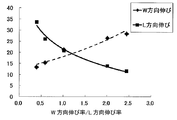
- the L direction is the extrusion direction during the extrusion process. Therefore, in the rare earth magnet intermediate produced by the extrusion process, the elongation in the W direction is very small, while the elongation in the L direction is large. For this reason, in the rare earth magnet intermediate, the magnetic properties in the L direction are greatly improved, while the improvement in the magnetic properties in the W direction is small.
- the magnetic properties in the L direction of the manufactured rare earth magnet and the W direction are increased by increasing the elongation in the W direction with respect to the elongation in the L direction.
- the magnetic characteristics of the surface can be made comparable, and the in-plane anisotropy formed by the L-direction axis and the W-direction axis can be eliminated.
- the surface formed by the L-direction axis and the W-direction axis It is possible to increase the anisotropy in the easy magnetization direction (C-axis direction) orthogonal to, and to improve the remanent magnetization Br of the rare earth magnet.
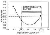
- In-plane anisotropy index Ratio of elongation in the W direction and elongation in the L direction during upsetting so that Br (W) / Br (L) is 1.2 or less: Elongation in the W direction / It has also been specified that the elongation in the L direction is in the range of 1 to 2.5.
- the ratio of the elongation rate in the W direction and the elongation rate in the L direction during upsetting L direction during upsetting so that the elongation rate in the W direction / L direction is in the range of 1 to 2.5
- the dimensions of the mold when the upset processing is performed while accommodating the rare earth magnet intermediate to be manufactured are adjusted so that the above ratio is obtained. Mention may be made of the use of a dimensional mold.
- the dimension of the plane formed by the L-direction axis and the W-direction axis of the plate-shaped rare earth magnet intermediate produced by extrusion is a method of adjusting the dimension of the plane formed by the L-direction axis and the W-direction axis of the plate-shaped rare earth magnet intermediate produced by extrusion. That is, when a rare-earth magnet intermediate having a rectangular shape in plan view is pressed and crushed from above and below with a punch or the like with no side restraint, the frictional force generated between the upper and lower punches and the upper and lower surfaces of the intermediate causes The elongation of the intermediate body along the direction is higher than the elongation along the long side.
- the length in the W direction is adjusted, and upsetting is performed on the rare earth magnet intermediate with the adjusted dimensions.
- the hot plastic working is performed in the order of the extrusion processing and the upsetting processing.
- high strain can be satisfactorily applied to the entire region of manufactured rare earth magnets.
- a rare earth magnet having a high degree of orientation and high residual magnetization can be produced.
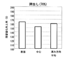
- FIG. 6 is a diagram showing an experimental result regarding a remanent magnetization improvement rate for each part of a rare earth magnet by extrusion processing at a processing rate of 70%.
- FIG. 6 is a diagram showing an experimental result on a residual magnetization improvement rate for each part of a rare earth magnet by upsetting with a processing rate of 25%.
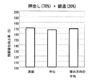
- FIG. 6 is a diagram showing an experimental result regarding a residual magnetization improvement rate for each part of a rare earth magnet by extrusion processing at a processing rate of 70% and upsetting processing at a processing rate of 25%.
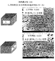
- FIG. 5 is a view showing an SEM image of a crystal structure of a rare earth magnet in the L direction and the W direction when the difference between the elongation in the L direction and the elongation in the W direction is large.
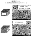
- FIG. 6 is a view showing SEM images of crystal structures in the L direction and W direction of a rare earth magnet when the difference between the elongation in the L direction and the elongation in the W direction is small.
- the illustrated example describes a method for producing a rare-earth magnet, which is a nanocrystalline magnet.
- the method for producing a rare-earth magnet of the present invention is not limited to the production of a nanocrystalline magnet, and relative crystal grains Of course, it can be applied to the production of large sintered magnets (for example, having a particle size of about 1 ⁇ m).
- the extrusion process in the second step of the illustrated example uses an extrusion punch having a plate-like hollow, and presses the molded body with this extrusion punch to reduce the thickness of the molded body, thereby forming the hollow body of the extrusion punch.
- a die having a plate-like hollow is used to form a molded body on this die.
- a processing method for producing a plate-like rare earth magnet intermediate body by extruding a part of a molded body from a hollow die while reducing the thickness of the molded body by pressing the molded body with a punch that does not contain a hollow (forward extrusion method) Of course, it may be.
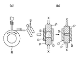
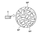
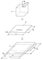
- FIGS. 1a and 1b are schematic views illustrating the first step of the first embodiment of the method for producing a rare earth magnet of the present invention in that order, and FIG. 2 is the microstructure of the molded body produced in the first step.
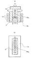
- FIG. 3a is a schematic diagram illustrating the extrusion method in the second step of the first embodiment of the manufacturing method
- FIG. 3b is a view taken along the line bb in FIG. 3a.
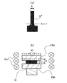
- FIG. 4a is a schematic diagram illustrating a state where an intermediate is manufactured by cutting a part of a processed product manufactured by extrusion processing
- FIG. 4b is a schematic diagram illustrating an upsetting method in the second step.
- an alloy ingot is melted at a high frequency by a melt spinning method using a single roll in a furnace (not shown) in an Ar gas atmosphere whose pressure is reduced to 50 kPa or less.
- a quenched ribbon B quenched ribbon
- a quenched ribbon B having a maximum dimension of about 200 nm or less is selected, and this is shown in FIG. Fill the cavity defined by the hard punch P. Then, while applying pressure with the carbide punch P (X direction), current is applied in the pressing direction to heat and heat, so that the main phase of the Nd-Fe-B system with a nanocrystal structure (crystal grain size of about 50 nm to 200 nm) ) And a square columnar shaped body S made of a grain boundary phase of an Nd—X alloy (X: metal element) around the main phase (first step).
- the RE content is preferably 29% by mass ⁇ RE ⁇ 32% by mass.
- the Nd—X alloy constituting the grain boundary phase is made of Nd and at least one alloy of Co, Fe, Ga, etc., for example, Nd—Co, Nd—Fe, Nd—Ga, One of Nd-Co-Fe and Nd-Co-Fe-Ga, or a mixture of two or more of these, is in an Nd-rich state.
- the compact S exhibits an isotropic crystal structure in which the grain boundary phase BP is filled between the nanocrystalline grains MP (main phase).
- the upsetting process shown in FIG. 4 is performed on the rare earth magnet intermediate manufactured by the extrusion process. Then, a rare earth magnet (orientated magnet) is manufactured by hot plastic working consisting of this extrusion and upsetting (second step).
- the second step will be described in more detail.
- the molded body manufactured in the first step is accommodated in the die Da, and the die Da is heated by the high frequency coil Co to form a heated molded body S '.
- a lubricant is applied to the inner surface of the die Da and the inner surface of the plate-like hollow PDa of the extrusion punch PD.
- the heated molded body S ′ is pressurized by the extrusion punch PD having the plate-like hollow PDa (in the Y1 direction), and the heated molded body S ′ is partially plate-like while reducing its thickness by this pressurization. Is extruded into the hollow PDa (Z direction).
- the processing rate at the time of this extrusion processing is represented by (t0-t1) / t0, and it is desirable to process at a processing rate of 60 to 80%.
- the rare earth magnet intermediate S ′′ shown in FIG. 4a is manufactured. Of the rare earth magnet intermediate S ′′, only a plate-like portion having a thickness t1 is cut to obtain a normal rare earth magnet intermediate. Applies to the next upsetting.
- a rare earth magnet intermediate S ′′ having a thickness t1 is placed between the upper and lower punches PM (anvil), the punch PM is heated by the high frequency coil Co, and the rare earth magnet intermediate S ′′ is heated. While pressing in the thickness direction of the rare earth magnet intermediate S ′′ with the upper punch PM (Y1 direction), the rare earth magnet C which is an oriented magnet is manufactured by reducing the thickness from the initial t1 to t2.
- the processing rate in this upsetting process is expressed as (t1-t2) / t1, and it is desirable to process at a processing rate of 10-30%.
- strain rate during extrusion and upsetting of hot plastic working is adjusted to 0.1 / sec or more. Further, when the degree of processing (compression ratio) by hot plastic working is large, for example, hot plastic working when the compressibility is about 10% or more can be referred to as strong working.
- the rare earth magnet intermediate produced by the first extrusion process has a high strain region formed on the surface thereof.
- the center becomes a low strain region, and the center anisotropy is insufficient as compared with the outer region.
- the second step by performing the hot plastic processing in the order of extrusion processing and upsetting processing, the following is performed for the low strain region in the central region of the rare earth magnet intermediate that is likely to occur during the extrusion processing.
- a high strain by upsetting a high strain can be imparted satisfactorily to the entire region of the rare earth magnet to be manufactured, and thus a rare earth magnet having a high degree of orientation and a high residual magnetization can be manufactured. Can do.
- the manufactured rare earth magnet C (orientated magnet) by hot plastic processing consisting of two stages of extrusion and upsetting, the nanocrystal grains MP have a flat shape, and the anisotropic axis
- the rare-earth magnet C is excellent in magnetic anisotropy.
- the RE-Fe-B main phase (RE: Nd, at least one of Pr, or an intermediate product thereof, Di (zidym)), and the RE- around the main phase. It has a metal structure consisting of the grain boundary phase of the X alloy (X: metal element), the content ratio of RE is 29 mass% ⁇ RE ⁇ 32 mass%, and the average grain of the main phase of the manufactured rare earth magnet The diameter should be 300 nm.
- the content ratio of RE is within the above range, the effect of suppressing the occurrence of cracks during hot plastic working is even higher, and a high degree of orientation can be guaranteed.
- the RE content is in the above range, the size of the main phase that can guarantee high remanent magnetization can be secured.
- FIG. 7 is a schematic diagram for explaining another embodiment of the second step. That is, the first step of the second embodiment of the manufacturing method is the same as that of the first embodiment of the manufacturing method, and an improvement is added to the second step.
- the molded body S manufactured in the first step has a C-axis direction that is an easy magnetization direction, and an L-direction axis and a W-direction axis that form a surface orthogonal to the C-axis direction.
- the extrusion direction in the second step of extrusion processing is the L direction (direction along the L direction axis), and the direction orthogonal to the extrusion direction in extrusion processing is the W direction (direction along the W direction axis). To do.
- the rare earth magnet intermediate S ′′ (thickness t 0 ) manufactured by the extrusion process in the second step, since the extrusion direction during the extrusion process is the L direction, the elongation in the W direction is slight. On the other hand, the elongation in the L direction is large (L 0 > W 0 ). Therefore, in the rare earth magnet intermediate S ′′, the magnetic characteristics in the L direction are greatly improved, while the improvement in the magnetic characteristics in the W direction is small.
- the manufactured rare earth magnet by increasing the extension in the W direction relative to the extension in the L direction (W 1 ⁇ W 0 > L 1 ⁇ L 0 ), the manufactured rare earth magnet
- the in-plane anisotropy formed by the L-direction axis and the W-direction axis can be eliminated by making the magnetic properties in the L direction and the W direction of C (thickness t 1 ) comparable.
- the size of the mold that accommodates the rare earth magnet intermediate S ′′ is adjusted, the rare earth magnet intermediate S ′′ is accommodated in the mold and forged, and the residual magnetization Br ( W) and the remanent magnetization Br (L) in the L direction.
- the elongation in the direction is in the range of approximately 1 to 2.5. Therefore, the dimensions of the mold used in the upsetting process are adjusted so that both of these elongation rates are obtained, and the rare-earth magnet intermediate S ′′ is adjusted using the mold whose dimensions are adjusted in this way.
- the elongation in the W direction and the elongation in the L direction can be precisely controlled.
- extrusion As another method for adjusting the in-plane anisotropy index: Br (W) / Br (L) to 1.2 or less, or the elongation in the W direction / the elongation in the L direction from 1 to 2.5, extrusion is used. There is a method in which the dimension of the plane formed by the L-direction axis and the W-direction axis of the plate-shaped rare earth magnet intermediate manufactured by processing is adjusted in advance.
- Rare earth alloy raw material (alloy composition is at%, Fe-30Nd-0.93B-4Co-0.4Ga) is blended in a predetermined amount, melted in Ar atmosphere, and then the molten metal is subjected to Cr plating from ⁇ 0.8mm orifice.
- the alloy flakes were manufactured by injecting into a Cu rotating roll and quenching. The alloy flakes were pulverized and sieved with a cutter mill in an Ar atmosphere to obtain a rare earth alloy powder of 0.2 mm or less. Next, this rare earth alloy powder was accommodated in a carbide die having a size of 20 ⁇ 20 ⁇ 40 mm, and the upper and lower sides were sealed with a carbide punch.
- this was set in a chamber, depressurized to 10 ⁇ 2 Pa, loaded with 400 MPa, heated with a high-frequency coil and heated to 650 ° C. and pressed. After the press working, the molded body (bulk body) was taken out from the die by holding for 60 seconds to obtain a molded body for hot working.
- the compact is accommodated in the die shown in FIG. 3, the die is heated with a high-frequency coil, the temperature of the compact is raised to about 800 ° C. by heat transfer from the die, and a stroke speed of 25 mm / sec (distortion speed 1 / Extrusion processing at a processing rate of 70% was performed at about sec). Thereafter, the produced intermediate body is taken out from the die, and only the intermediate portion of the plate-like portion is cut out as shown in FIG. 4, and the cut-out plate-like intermediate body is placed on the die (anvil) as shown in FIG. 4b.
- the anvil is heated with a high-frequency coil
- the intermediate is heated to 800 ° C by heat transfer from the die, and upsetting with a stroke rate of 4 mm / sec (strain rate of about 1 / sec) and a machining rate of 25% is performed.
- a stroke rate of 4 mm / sec strain rate of about 1 / sec
- a machining rate of 25% is performed.
- FIG. 8 is a diagram showing an experimental result regarding a remanent magnetization improvement rate for each part of the rare earth magnet by extrusion processing with a processing rate of 70%.
- FIG. 9 is a diagram showing experimental results regarding the residual magnetization improvement rate for each part of the rare earth magnet by upsetting with a working rate of 25%.
- FIG. 10 is a diagram showing the experimental results regarding the remanent magnetization improvement rate for each part of the rare earth magnet by extrusion processing at a processing rate of 70% and upsetting processing at a processing rate of 25%.
- the center residual magnetization is about 10% lower than the residual magnetization on the surface.
- the residual magnetization at the center is about 10% higher than the residual magnetization on the surface.
- the processed products by extrusion and upsetting have a remanent magnetization on the surface and in the center, and the remanent magnetization near the center having a low remanent magnetization is upset at the stage of extrusion. It has been proved that the processed product has improved by processing and has a high remanent magnetization of the same level as a whole.
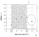
- the remanent magnetization of the rare earth magnet becomes the highest when the processing rate during extrusion is in the range of 50% to 80% (region I in FIG. 11).
- the value of the remanent magnetization is smaller than 90% when the processing rate at the time of extrusion processing is 50%, but by adding upsetting after that, the remanent magnetization can be increased, and at the time of extrusion processing When the processing rate is 90%, cracks occur and upsetting cannot be applied.
- both extrusion and upsetting are performed with a processing rate in the range of 50% to 80%.
- the processing rate during upsetting is less than 10% ( In the area II) of FIG. 12, it is simply assumed that the center of the rare earth magnet cannot be sufficiently distorted and that the entire area of the rare earth magnet cannot have high remanent magnetization. It is specified from the CAE analysis by the present inventors, etc., that evaluates the strain distribution when embedding is performed (the friction coefficient at that time is set to 0.3).
- the extrusion process is performed in the processing rate range of 50 to 80%, and then the upsetting process is performed in the processing rate range of 10 to 50%.
- Method for producing specimen 2 With respect to the method of manufacturing the test body, it is the same as the method 1 of manufacturing the test body described above until only the intermediate part of the plate-shaped part is cut out, and then the anvil is heated with a high-frequency coil, The intermediate was heated to 800 ° C., and upsetting was performed at a processing rate of 30% at a stroke speed of 4 mm / sec (strain rate of about 1 / sec) to obtain a rare earth magnet specimen.
- the elongation ratio in the W direction / elongation ratio in the L direction of the rare earth magnet shown in FIG. 7: ⁇ (W 1 ⁇ W 0 ) / W 0 ⁇ / ⁇ (L 1 ⁇ L 0 ) / L 0 ⁇ is 0.4. It was controlled in 5 stages from ⁇ 2.5.
- Table 2 below shows the W direction, L direction elongation rate, W direction elongation rate / L direction elongation rate, etc. of each specimen, and the relationship between the W direction elongation / L direction elongation and the elongation rate in each direction. Is shown in FIG.
- the in-plane anisotropy index exceeds 1.20 in the range where the elongation rate in the W direction / the elongation rate in the L direction exceeds 2.5, and deviates from the specified range of 1.20 or less.
- the range of the elongation rate in the W direction / the elongation rate in the L direction can be defined as a preferable range of 1.0 to 2.5.
- the in-plane anisotropy index is the in-plane anisotropy represented by the ratio of the residual magnetization Br (W) in the W direction and the residual magnetization Br (L) in the L direction after upsetting. Sex index: Br (W) / Br (L). The result of the experiment is shown in FIG.
- FIG. 15 confirms that the in-plane anisotropy index is 1.2 and the inflection point of the remanent magnetization is reached, and in the range of 1.2 or less, a high remanent magnetization of around 1.37 T is obtained.
- the in-plane anisotropy index: Br (W) expressed by the ratio of the residual magnetization Br (W) in the W direction to the residual magnetization Br (L) in the L direction after upsetting The elongation in the L direction and the elongation in the W direction during upsetting were adjusted so that / Br (L) was 1.2 or less.
- the alignment state in the L direction and the alignment state in the W direction are the same, and as a result, the C axis
- the residual magnetization in the direction is as high as 1.370.
- R Copper roll
- B Quenched ribbon (quenched ribbon)
- D Carbide die
- P Carbide punch
- PD Extrusion punch (anvil)
- PDa Plate-shaped hollow, Da ... Die, Co ... High frequency coil
- PM ... punch (anvil) S ... molded body
- S '... heated molded body S "... rare earth magnet intermediate, C ... rare earth magnet (orientated magnet), RM ... rare earth magnet, MP ... main phase (nano Crystal grain, crystal grain, crystal), BP ... grain boundary phase
Priority Applications (8)
| Application Number | Priority Date | Filing Date | Title |
|---|---|---|---|
| RU2015113451/02A RU2595073C1 (ru) | 2012-10-23 | 2013-10-17 | Способ изготовления редкоземельного магнита |
| KR1020157007546A KR101632853B1 (ko) | 2012-10-23 | 2013-10-17 | 희토류 자석의 제조 방법 |
| CN201380055338.0A CN104737251B (zh) | 2012-10-23 | 2013-10-17 | 稀土类磁铁的制造方法 |
| US14/436,959 US9905362B2 (en) | 2012-10-23 | 2013-10-17 | Rare-earth magnet production method |
| IN3164DEN2015 IN2015DN03164A (pt) | 2012-10-23 | 2013-10-17 | |
| EP13848858.0A EP2913831B1 (en) | 2012-10-23 | 2013-10-17 | Rare-earth-magnet production method |
| CA2887984A CA2887984C (en) | 2012-10-23 | 2013-10-17 | Rare-earth magnet production method |
| BR112015008267-0A BR112015008267B1 (pt) | 2012-10-23 | 2013-10-17 | Método para fabricar um imã de terras-raras |
Applications Claiming Priority (4)
| Application Number | Priority Date | Filing Date | Title |
|---|---|---|---|
| JP2012233812 | 2012-10-23 | ||
| JP2012-233812 | 2012-10-23 | ||
| JP2013-212883 | 2013-10-10 | ||
| JP2013212883A JP6044504B2 (ja) | 2012-10-23 | 2013-10-10 | 希土類磁石の製造方法 |
Publications (1)
| Publication Number | Publication Date |
|---|---|
| WO2014065188A1 true WO2014065188A1 (ja) | 2014-05-01 |
Family
ID=50544568
Family Applications (1)
| Application Number | Title | Priority Date | Filing Date |
|---|---|---|---|
| PCT/JP2013/078191 WO2014065188A1 (ja) | 2012-10-23 | 2013-10-17 | 希土類磁石の製造方法 |
Country Status (11)
| Country | Link |
|---|---|
| US (1) | US9905362B2 (pt) |
| EP (1) | EP2913831B1 (pt) |
| JP (1) | JP6044504B2 (pt) |
| KR (1) | KR101632853B1 (pt) |
| CN (1) | CN104737251B (pt) |
| BR (1) | BR112015008267B1 (pt) |
| CA (1) | CA2887984C (pt) |
| IN (1) | IN2015DN03164A (pt) |
| RU (1) | RU2595073C1 (pt) |
| TW (1) | TWI466141B (pt) |
| WO (1) | WO2014065188A1 (pt) |
Families Citing this family (14)
| Publication number | Priority date | Publication date | Assignee | Title |
|---|---|---|---|---|
| KR20150033423A (ko) * | 2013-09-24 | 2015-04-01 | 엘지전자 주식회사 | 열간가압성형 공정을 이용한 이방성 열간가압성형 자석의 제조방법 및 이 방법으로 제조된 열간가압성형 자석 |
| JP6168090B2 (ja) | 2014-08-28 | 2017-07-26 | トヨタ自動車株式会社 | 成形型 |
| CN104575906B (zh) * | 2014-12-11 | 2017-05-24 | 赣州市东磁稀土有限公司 | 一种高性能低成本稀土永磁材料及其制备方法 |
| JP6689571B2 (ja) | 2015-03-05 | 2020-04-28 | 信越化学工業株式会社 | 希土類焼結磁石の製造方法 |
| CN104733148B (zh) * | 2015-03-31 | 2017-06-16 | 安徽省瀚海新材料股份有限公司 | 一种高性能Re‑TM‑B永磁材料的制作方法 |
| JP6365447B2 (ja) | 2015-07-08 | 2018-08-01 | トヨタ自動車株式会社 | ロータの製造方法 |
| CN105206371A (zh) * | 2015-10-13 | 2015-12-30 | 南通长江电器实业有限公司 | 一种低成本高矫顽力稀土永磁材料 |
| CN105537577A (zh) * | 2015-12-17 | 2016-05-04 | 中磁科技股份有限公司 | Nd-Fe-B粉末颗粒动态取向方法 |
| CN106964778A (zh) * | 2016-01-14 | 2017-07-21 | 罗伯特·博世有限公司 | 生产热变形磁体的方法和设备 |
| DE102016217138A1 (de) | 2016-09-08 | 2018-03-08 | Robert Bosch Gmbh | Verfahren und zugehörige Schmiedehohlform zur Herstellung eines heißumgeformten Magneten |
| KR102347739B1 (ko) * | 2017-12-11 | 2022-01-06 | 현대자동차주식회사 | 강자계 방식 열간 압출 영구자석 제조공법 및 ipm 모터 |
| JP7201332B2 (ja) * | 2018-04-09 | 2023-01-10 | トヨタ自動車株式会社 | 希土類磁石の製造方法及びそれに用いられる製造装置 |
| CN111326336B (zh) * | 2020-02-28 | 2021-06-22 | 大连理工大学 | 一种振荡式热变形和渗透一体化的高矫顽力稀土永磁体制备方法 |
| CN112170848B (zh) * | 2020-07-23 | 2023-06-09 | 湖州机床厂有限公司 | 铝合金粉末挤锻成形设备及挤锻成形方法 |
Citations (10)
| Publication number | Priority date | Publication date | Assignee | Title |
|---|---|---|---|---|
| JPH01248503A (ja) * | 1988-03-29 | 1989-10-04 | Daido Steel Co Ltd | R−Fe−B系異方性磁石の製造方法 |
| JPH02250918A (ja) | 1989-03-25 | 1990-10-08 | Kobe Steel Ltd | 希土類元素―遷移元素―b系磁石の製造方法 |
| JPH02250919A (ja) | 1989-03-25 | 1990-10-08 | Kobe Steel Ltd | 希土類元素―遷移元素―b系磁石の製造方法 |
| JPH02250920A (ja) | 1989-03-25 | 1990-10-08 | Kobe Steel Ltd | 希土類元素―遷移元素―b系磁石の鍛造による製造方法 |
| JPH02250922A (ja) | 1989-03-25 | 1990-10-08 | Kobe Steel Ltd | 希土類元素―遷移元素―b系磁石の製造方法 |
| JPH0444301A (ja) | 1990-06-12 | 1992-02-14 | Seiko Epson Corp | 希土類永久磁石の製造方法 |
| JPH04134804A (ja) | 1990-09-27 | 1992-05-08 | Seiko Epson Corp | 希土類永久磁石の製造方法 |
| JPH05129128A (ja) * | 1991-11-05 | 1993-05-25 | Hitachi Metals Ltd | リング形状永久磁石およびその製造方法 |
| JPH05166655A (ja) * | 1991-12-18 | 1993-07-02 | Seiko Epson Corp | 樹脂結合型磁石の製造方法 |
| JP2008091867A (ja) | 2006-09-06 | 2008-04-17 | Daido Steel Co Ltd | 永久磁石の製造方法および永久磁石 |
Family Cites Families (15)
| Publication number | Priority date | Publication date | Assignee | Title |
|---|---|---|---|---|
| WO1988006797A1 (en) * | 1987-03-02 | 1988-09-07 | Seiko Epson Corporation | Rare earth element-iron base permanent magnet and process for its production |
| EP0261292B1 (en) * | 1986-07-28 | 1992-06-10 | Crucible Materials Corporation | Method of producing fully dense permanent magnet alloy article |
| SU1622082A1 (ru) * | 1988-09-27 | 1991-01-23 | Институт проблем сверхпластичности металлов АН СССР | Способ получени анизотропных посто нных магнитов из быстрозакаленных сплавов системы железо-редкоземельный элемент-бор |
| US5085716A (en) * | 1990-02-20 | 1992-02-04 | General Motors Corporation | Hot worked rare earth-iron-carbon magnets |
| JPH044301A (ja) | 1990-04-18 | 1992-01-08 | Matsushita Electric Ind Co Ltd | 空気圧駆動装置 |
| JP3261050B2 (ja) | 1996-11-29 | 2002-02-25 | 山陽特殊製鋼株式会社 | 赤道状に異方化された球状Cu−Ni−Fe合金磁石の製造方法 |
| TWI290958B (en) * | 2004-04-16 | 2007-12-11 | Nippon Steel Corp | A non-oriented electrical steel sheet having excellent punchability and magnetic property after stress-relief annealing and a method of production of the same |
| JP4938285B2 (ja) * | 2005-10-28 | 2012-05-23 | トヨタ自動車株式会社 | コア/シェル複合ナノ粒子を製造する方法 |
| RU2337975C2 (ru) * | 2006-12-11 | 2008-11-10 | Дмитрий Валерьевич Гундеров | Способ получения постоянных магнитов из сплавов на основе системы неодим-железо-бор или празеодим-железо-бор |
| JP2008172037A (ja) * | 2007-01-12 | 2008-07-24 | Daido Steel Co Ltd | 希土類磁石及びその製造方法 |
| JP5509850B2 (ja) * | 2007-07-02 | 2014-06-04 | 日立金属株式会社 | R−Fe−B系希土類焼結磁石およびその製造方法 |
| JP5125818B2 (ja) * | 2007-07-24 | 2013-01-23 | 日産自動車株式会社 | 磁性体成形体およびその製造方法 |
| JP4589374B2 (ja) * | 2007-11-02 | 2010-12-01 | 株式会社豊田中央研究所 | 磁心用粉末及び圧粉磁心並びにそれらの製造方法 |
| EP2511920B1 (en) * | 2009-12-09 | 2016-04-27 | Aichi Steel Corporation | Process for production of rare earth anisotropic magnet |
| JP5413383B2 (ja) | 2011-02-23 | 2014-02-12 | トヨタ自動車株式会社 | 希土類磁石の製造方法 |
-
2013
- 2013-10-10 JP JP2013212883A patent/JP6044504B2/ja active Active
- 2013-10-17 CN CN201380055338.0A patent/CN104737251B/zh not_active Expired - Fee Related
- 2013-10-17 BR BR112015008267-0A patent/BR112015008267B1/pt not_active IP Right Cessation
- 2013-10-17 KR KR1020157007546A patent/KR101632853B1/ko active IP Right Grant
- 2013-10-17 CA CA2887984A patent/CA2887984C/en active Active
- 2013-10-17 IN IN3164DEN2015 patent/IN2015DN03164A/en unknown
- 2013-10-17 RU RU2015113451/02A patent/RU2595073C1/ru active
- 2013-10-17 EP EP13848858.0A patent/EP2913831B1/en not_active Not-in-force
- 2013-10-17 US US14/436,959 patent/US9905362B2/en active Active
- 2013-10-17 WO PCT/JP2013/078191 patent/WO2014065188A1/ja active Application Filing
- 2013-10-22 TW TW102138082A patent/TWI466141B/zh not_active IP Right Cessation
Patent Citations (10)
| Publication number | Priority date | Publication date | Assignee | Title |
|---|---|---|---|---|
| JPH01248503A (ja) * | 1988-03-29 | 1989-10-04 | Daido Steel Co Ltd | R−Fe−B系異方性磁石の製造方法 |
| JPH02250918A (ja) | 1989-03-25 | 1990-10-08 | Kobe Steel Ltd | 希土類元素―遷移元素―b系磁石の製造方法 |
| JPH02250919A (ja) | 1989-03-25 | 1990-10-08 | Kobe Steel Ltd | 希土類元素―遷移元素―b系磁石の製造方法 |
| JPH02250920A (ja) | 1989-03-25 | 1990-10-08 | Kobe Steel Ltd | 希土類元素―遷移元素―b系磁石の鍛造による製造方法 |
| JPH02250922A (ja) | 1989-03-25 | 1990-10-08 | Kobe Steel Ltd | 希土類元素―遷移元素―b系磁石の製造方法 |
| JPH0444301A (ja) | 1990-06-12 | 1992-02-14 | Seiko Epson Corp | 希土類永久磁石の製造方法 |
| JPH04134804A (ja) | 1990-09-27 | 1992-05-08 | Seiko Epson Corp | 希土類永久磁石の製造方法 |
| JPH05129128A (ja) * | 1991-11-05 | 1993-05-25 | Hitachi Metals Ltd | リング形状永久磁石およびその製造方法 |
| JPH05166655A (ja) * | 1991-12-18 | 1993-07-02 | Seiko Epson Corp | 樹脂結合型磁石の製造方法 |
| JP2008091867A (ja) | 2006-09-06 | 2008-04-17 | Daido Steel Co Ltd | 永久磁石の製造方法および永久磁石 |
Non-Patent Citations (2)
| Title |
|---|
| See also references of EP2913831A4 |
| YOICHI SAKAMOTO ET AL.: "Men Ihosei MnAlC Jishaku", NATIONAL TECHNICAL REPORT 0028-0291, vol. 28, no. 6, December 1982 (1982-12-01), pages 1171 - 1180, XP008176506 * |
Also Published As
| Publication number | Publication date |
|---|---|
| RU2595073C1 (ru) | 2016-08-20 |
| KR20150052114A (ko) | 2015-05-13 |
| US9905362B2 (en) | 2018-02-27 |
| EP2913831B1 (en) | 2017-04-19 |
| BR112015008267A2 (pt) | 2017-07-04 |
| TWI466141B (zh) | 2014-12-21 |
| CA2887984A1 (en) | 2014-05-01 |
| CN104737251A (zh) | 2015-06-24 |
| BR112015008267B1 (pt) | 2021-10-05 |
| TW201430873A (zh) | 2014-08-01 |
| JP6044504B2 (ja) | 2016-12-14 |
| IN2015DN03164A (pt) | 2015-10-02 |
| KR101632853B1 (ko) | 2016-06-22 |
| EP2913831A4 (en) | 2015-11-25 |
| CN104737251B (zh) | 2017-12-08 |
| US20150287530A1 (en) | 2015-10-08 |
| JP2014103386A (ja) | 2014-06-05 |
| CA2887984C (en) | 2016-09-06 |
| EP2913831A1 (en) | 2015-09-02 |
Similar Documents
| Publication | Publication Date | Title |
|---|---|---|
| JP6044504B2 (ja) | 希土類磁石の製造方法 | |
| KR101690896B1 (ko) | 희토류 자석의 제조 방법 | |
| KR101513824B1 (ko) | 희토류 자석 제조 방법 | |
| KR101664726B1 (ko) | 희토류 자석의 제조 방법 | |
| KR101813427B1 (ko) | 희토류 자석의 제조 방법 | |
| WO2014080852A1 (ja) | 希土類磁石の製造方法 | |
| JP2015093312A (ja) | 前方押出し鍛造装置および前方押出し鍛造方法 | |
| JP6102881B2 (ja) | 希土類磁石の製造方法 | |
| JP5704186B2 (ja) | 希土類磁石の製造方法 | |
| JP2016076614A (ja) | 希土類磁石の製造方法 | |
| WO2015097517A1 (en) | Forward extrusion forging apparatus and forward extrusion forging method | |
| CN108242334B (zh) | 稀土磁铁的制造方法 | |
| JP6354684B2 (ja) | 塑性加工方法 | |
| JP2015090888A (ja) | 希土類磁石の製造方法 | |
| JP2013138111A (ja) | 希土類磁石の製造方法 |
Legal Events
| Date | Code | Title | Description |
|---|---|---|---|
| 121 | Ep: the epo has been informed by wipo that ep was designated in this application |
Ref document number: 13848858 Country of ref document: EP Kind code of ref document: A1 |
|
| ENP | Entry into the national phase |
Ref document number: 20157007546 Country of ref document: KR Kind code of ref document: A |
|
| ENP | Entry into the national phase |
Ref document number: 2887984 Country of ref document: CA |
|
| WWE | Wipo information: entry into national phase |
Ref document number: 14436959 Country of ref document: US |
|
| REEP | Request for entry into the european phase |
Ref document number: 2013848858 Country of ref document: EP |
|
| WWE | Wipo information: entry into national phase |
Ref document number: 2013848858 Country of ref document: EP |
|
| NENP | Non-entry into the national phase |
Ref country code: DE |
|
| REG | Reference to national code |
Ref country code: BR Ref legal event code: B01A Ref document number: 112015008267 Country of ref document: BR |
|
| ENP | Entry into the national phase |
Ref document number: 2015113451 Country of ref document: RU Kind code of ref document: A |
|
| ENP | Entry into the national phase |
Ref document number: 112015008267 Country of ref document: BR Kind code of ref document: A2 Effective date: 20150414 |