WO2014061256A1 - 磁力選別装置、磁力選別方法および鉄源の製造方法 - Google Patents
磁力選別装置、磁力選別方法および鉄源の製造方法 Download PDFInfo
- Publication number
- WO2014061256A1 WO2014061256A1 PCT/JP2013/006109 JP2013006109W WO2014061256A1 WO 2014061256 A1 WO2014061256 A1 WO 2014061256A1 JP 2013006109 W JP2013006109 W JP 2013006109W WO 2014061256 A1 WO2014061256 A1 WO 2014061256A1
- Authority
- WO
- WIPO (PCT)
- Prior art keywords
- belt
- conveyor
- magnetic
- guide roll
- roll
- Prior art date
- Legal status (The legal status is an assumption and is not a legal conclusion. Google has not performed a legal analysis and makes no representation as to the accuracy of the status listed.)
- Ceased
Links
Images


Classifications
-
- B—PERFORMING OPERATIONS; TRANSPORTING
- B03—SEPARATION OF SOLID MATERIALS USING LIQUIDS OR USING PNEUMATIC TABLES OR JIGS; MAGNETIC OR ELECTROSTATIC SEPARATION OF SOLID MATERIALS FROM SOLID MATERIALS OR FLUIDS; SEPARATION BY HIGH-VOLTAGE ELECTRIC FIELDS
- B03C—MAGNETIC OR ELECTROSTATIC SEPARATION OF SOLID MATERIALS FROM SOLID MATERIALS OR FLUIDS; SEPARATION BY HIGH-VOLTAGE ELECTRIC FIELDS
- B03C1/00—Magnetic separation
- B03C1/02—Magnetic separation acting directly on the substance being separated
- B03C1/16—Magnetic separation acting directly on the substance being separated with material carriers in the form of belts
- B03C1/18—Magnetic separation acting directly on the substance being separated with material carriers in the form of belts with magnets moving during operation
-
- B—PERFORMING OPERATIONS; TRANSPORTING
- B03—SEPARATION OF SOLID MATERIALS USING LIQUIDS OR USING PNEUMATIC TABLES OR JIGS; MAGNETIC OR ELECTROSTATIC SEPARATION OF SOLID MATERIALS FROM SOLID MATERIALS OR FLUIDS; SEPARATION BY HIGH-VOLTAGE ELECTRIC FIELDS
- B03C—MAGNETIC OR ELECTROSTATIC SEPARATION OF SOLID MATERIALS FROM SOLID MATERIALS OR FLUIDS; SEPARATION BY HIGH-VOLTAGE ELECTRIC FIELDS
- B03C1/00—Magnetic separation
- B03C1/02—Magnetic separation acting directly on the substance being separated
- B03C1/025—High gradient magnetic separators
- B03C1/031—Component parts; Auxiliary operations
- B03C1/033—Component parts; Auxiliary operations characterised by the magnetic circuit
- B03C1/0332—Component parts; Auxiliary operations characterised by the magnetic circuit using permanent magnets
-
- B—PERFORMING OPERATIONS; TRANSPORTING
- B03—SEPARATION OF SOLID MATERIALS USING LIQUIDS OR USING PNEUMATIC TABLES OR JIGS; MAGNETIC OR ELECTROSTATIC SEPARATION OF SOLID MATERIALS FROM SOLID MATERIALS OR FLUIDS; SEPARATION BY HIGH-VOLTAGE ELECTRIC FIELDS
- B03C—MAGNETIC OR ELECTROSTATIC SEPARATION OF SOLID MATERIALS FROM SOLID MATERIALS OR FLUIDS; SEPARATION BY HIGH-VOLTAGE ELECTRIC FIELDS
- B03C2201/00—Details of magnetic or electrostatic separation
- B03C2201/20—Magnetic separation of bulk or dry particles in mixtures
-
- B—PERFORMING OPERATIONS; TRANSPORTING
- B03—SEPARATION OF SOLID MATERIALS USING LIQUIDS OR USING PNEUMATIC TABLES OR JIGS; MAGNETIC OR ELECTROSTATIC SEPARATION OF SOLID MATERIALS FROM SOLID MATERIALS OR FLUIDS; SEPARATION BY HIGH-VOLTAGE ELECTRIC FIELDS
- B03C—MAGNETIC OR ELECTROSTATIC SEPARATION OF SOLID MATERIALS FROM SOLID MATERIALS OR FLUIDS; SEPARATION BY HIGH-VOLTAGE ELECTRIC FIELDS
- B03C2201/00—Details of magnetic or electrostatic separation
- B03C2201/22—Details of magnetic or electrostatic separation characterised by the magnetic field, e.g. its shape or generation
Definitions
- the present invention relates to a technique for magnetically sorting (separating) ferromagnetic particles from a granular material containing ferromagnetic particles (eg, ferromagnetic particles).
- the present invention relates to iron from slag, which is a by-product of the iron making process.
- the present invention relates to a magnetic separation device, a magnetic separation method, and a method for producing an iron source, which are suitable for separating steel.
- slag steel slag
- Slag is generated as a by-product in the hot metal pretreatment and converter decarburization process. Slag is obtained by reacting and generating these impurities and unnecessary elements with a calcium-based additive added to remove impurities and unnecessary elements in the hot metal and molten steel. The slag contains a lot of iron in addition to the removed impurities and unnecessary elements.
- ⁇ Separation and recovery of iron is performed to recycle iron in slag.
- iron is separated and recovered in the following steps.
- the slag is sieved to remove large (several hundred mm) lumps contained in the slag.
- the small lump that has passed through the sieve is fixed with iron and slag, so rough crushing with a hammer crusher or rod mill, etc., and a size of several tens of ⁇ m to several tens of mm Furthermore, it promotes liberation (separation of slag and iron).
- the iron content is separated by a magnetic separator.
- the magnetic separator generally, suspended type (suspended electromagnets), drum type (magnetic drums) separators, pulley type (magnetic pulleys) and the like are used.
- the slag is heated in order to separate the iron component, cooled for an appropriate time, and then crushed. Depending on the cooling time, it is possible to separate only the fixed slag without crushing the iron ingot, or to pulverize the slag to about several tens of ⁇ m.
- the diameter may be reduced by heat treatment.
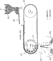
- Non-Patent Document 1 When performing magnetic sorting for iron recovery, a magnetic sorting device as shown in FIG. 8 is conventionally used (for example, Non-Patent Document 1).
- This device is a pulley type (belt conveyor type) magnetic force sorting device, which supplies a granular material a containing ferromagnetic particles from the supply device 23 onto the conveyor belt 20, and the granular material a from the conveyor terminal portion 27.
- ferromagnetic particles and non-magnetic particles are separated.
- magnets 22 In the belt guide roll 21 on the conveyor terminal end 27 side, magnets 22 are arranged in a part of the inner circumferential direction. The magnets 22 are arranged so that adjacent magnetic poles have different magnetism in the circumferential direction of the belt guide roll 21.
- the magnet 22 is a fixed magnet installed independently from the belt guide roll 21.
- the magnetic force of the magnet 22 inside the belt guide roll 21 acts on the granular material a on the conveyor belt 20 at the conveyor terminal portion 27, and nonmagnetic particles that are not attracted to the magnet 22 are generated.
- the ferromagnetic particles that fall first and are collected by the non-magnetized matter collecting unit 24y and attracted to the magnet 22 pass through the partition plate 25 provided below the belt guide roll 21, and fall at a position where the magnetic force is weakened.
- the magnetic deposit collection unit 24x collects the magnetic deposit.
- JP 2006-142136 A Japanese Patent Laid-Open No. 10-130041
- the supply amount of the granular material a is reduced by using a vibration feeder 26 or the like, and the thickness of the granular material layer on the conveyor belt 20 is, for example, It is necessary to take measures such as reducing the thickness to about one or two particles.
- the processing speed is slowed although the performance of selecting the ferromagnetic particles is ensured.
- magnetic separation of slag since it is necessary to process several tons to several tens of tons per hour, it is essential to perform a large amount of magnetic separation in a short time. Therefore, it is difficult to magnetically sort a large amount of powder particles a in a short time with the conventional magnetic sorting apparatus as described above.
- Patent Document 1 proposes a method for separating foreign matter without excessively crushing slag by passing through a plurality of specific steps, but there is a problem that a complicated separation flow occurs and processing costs increase. is there. Moreover, as shown in Patent Document 2, a wet process is generally applied in order to avoid agglomeration, but there is a problem that the waste liquid treatment cost becomes enormous.
- the object of the present invention is to solve the problems of the prior art as described above, even when a large amount of powder containing ferromagnetic particles is processed or when the layer of supplied powder is thick. It is an object of the present invention to provide a magnetic separation apparatus and a magnetic separation method that can efficiently separate ferromagnetic particles from the magnetic particles and can perform magnetic separation at low cost without requiring complicated processes and waste liquid treatment.
- the present inventors have obtained the following knowledge regarding magnetic sorting.
- the ferromagnetic particles When using a moving magnet to select ferromagnetic particles from a mixture of ferromagnetic particles and non-magnetic particles, when the movement of each particle is observed, the ferromagnetic particles are first attracted to the magnet. Move as expected. The attractive force acting on the ferromagnetic particles changes due to the change in the strength of the magnetic field accompanying the movement of the magnet. When the magnetic field is strong, the ferromagnetic particles come to gather together by attractive force, and conversely, when the magnetic field is weak, they tend to disperse.
- This change in attractive force has an effect similar to vibration on the granular material, and the change in the strength of the magnetic field is repeated, eliminating the pinching / embracing state of the non-magnetic particles by the ferromagnetic particles. .
- separation of ferromagnetic particles and nonmagnetic particles is promoted.
- the rotational force is applied to the ferromagnetic particles due to the change in the direction of the magnetic field, the ferromagnetic particles move to the magnet side while rotating between the nonmagnetic particles. Due to these two effects, many ferromagnetic particles gradually gather near the magnet, and the non-magnetic particles move to the side farther from the magnet.
- the ferromagnetic particles and the nonmagnetic particles can be separated by utilizing the change in the magnitude and direction of the magnetic field.
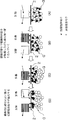
- FIGS. 1A to 1D schematically show the above action.
- the magnetic poles of the portion of the magnet that are opposed to the granular material are represented as N and S poles.
- the magnet moves and the gap between the N and S poles becomes as shown in FIG. 1 (B).
- the magnitude of the attractive force acting on the ferromagnetic particles changes due to the change in the magnitude of the magnetic field.
- the ferromagnetic particles are attracted in the direction of the arrow and move to the magnet side while rolling. Thereafter, as shown in FIG. 1C, the ferromagnetic particles are attracted to the south pole and further move to the magnet side.
- the ferromagnetic particles initially distributed over the entire granular layer are collected on the closest side of the granular layer to the magnet as shown in FIG. 1 (D). become.
- This phenomenon always occurs when at least one of the magnet and the granular material a is moving, and is the same even when the magnet is fixed and only the granular material a is moving.
- 1A to 1D show the case where the magnet moves from the right side to the left side of the figure, but the principle is the same even when the magnet moves from the left side to the right side of the figure. .
- the present inventors apply the above-described mechanism to a belt conveyor type magnetic separator, and face the powder particles along the circumferential direction of the belt guide roll inside the belt guide roll on the conveyor terminal end side.
- the magnets are arranged so that the adjacent magnetic poles of the portions are different from each other, and the adjacent magnetic poles in the portion facing the granular material in the width direction of the belt guide roll are the same. It was found that the magnetic particles can be efficiently magnetically selected by moving the powder particles in the magnetic field to be formed. If the magnitude and direction of the magnetic field acting on the ferromagnetic particles are changed at high speed by rotating the magnet, the effect is further enhanced.
- a conveyor belt that conveys powder particles containing ferromagnetic particles
- a rotatable hollow belt guide roll around which a conveyor belt is wound around a part of the outer periphery, Magnetic field application means installed inside the belt guide roll,
- the magnetic field applying means has a plurality of magnets inside the belt guide roll, The magnetism is arranged such that adjacent magnetic poles are different in the circumferential direction of the belt guide roll and the adjacent magnetic poles are the same in the width direction of the belt guide roll.
- a magnetic field change frequency F which is defined by the following formula (1) and indicates the number of magnetic pole changes applied to the granular material from the magnetic field applying means, is 170 Hz or more. Sorting device.
- a first belt conveyor (A) that conveys a granular material containing ferromagnetic particles
- a second belt conveyor (B) located above the belt conveyor;
- a magnetic field applying means comprising a plurality of magnets arranged in the circumferential direction of the belt guide roll, The conveyor start end of the belt conveyor (B) is positioned close to the upper end of the conveyor of the belt conveyor (A), The magnets are arranged so that the magnetic poles adjacent to each other in the circumferential direction of the belt guide roll of the belt conveyor (B) have different magnetism, and are adjacent in the width direction of the belt guide roll of the belt conveyor (B).
- the magnetic force sorting apparatus according to [1] or [2], wherein the magnetic poles to be arranged are arranged to be the same.
- a first belt conveyor (A) that conveys a granular material containing ferromagnetic particles
- a second belt conveyor (B) located above the belt conveyor (A), The conveyor start end of the belt conveyor (B) is positioned close to the upper end of the conveyor of the belt conveyor (A), The conveyor belts of the belt conveyors (A) and (B) are moving in the same direction at the conveyor terminal end of the belt conveyor (A) and the conveyor start end of the belt conveyor (B),
- the magnetic field applying means includes a plurality of magnets arranged in a belt guide roll circumferential direction and a width direction inside the belt guide roll on the conveyor start end side of the belt conveyor (B), The magnet The magnetic poles adjacent to each other in the belt guide roll circumferential direction of the belt conveyor (B) are arranged to be different from each other,
- the magnetic force sorting apparatus according to [1] or [2
- a first belt conveyor (A) that conveys a granular material containing ferromagnetic particles
- a second belt conveyor (B) located above the belt conveyor (A);
- a magnetic field application means having a plurality of magnets inside the belt guide roll on the conveyor start end side of the belt conveyor (B), Above the conveyor belt of the belt conveyor (A), the conveyor start end of the belt conveyor (B) is located close between the conveyor terminal portion of the belt conveyor (A) and the granular material supply device,
- the conveyor belts of the belt conveyors (A) and (B) are moving in the opposite directions at the conveyor terminal end of the belt conveyor (A) and the conveyor start end of the belt conveyor (B),
- the magnets are arranged such that adjacent magnetic poles differ in the circumferential direction of the belt guide roll of the belt conveyor (B), and adjacent magnetic poles in the width direction of the belt guide roll of the belt conveyor (B).
- the magnetic separator according to [1] or [2], which is arranged to be the same.
- the magnetic field application means of the belt conveyor (B) includes a rotatable magnet roll disposed inside the belt guide roll, The magnet rolls are arranged such that magnets arranged along the outer periphery thereof have different magnetic poles adjacent to each other in the circumferential direction of the belt guide roll of the belt conveyor (B), and of the belt conveyor (B).
- the magnetic force sorting apparatus according to any one of [3] to [5], which is arranged so that adjacent magnetic poles in the width direction of the belt guide roll are the same.
- a magnetized material recovery unit is provided below the conveyor terminal portion of the belt conveyor (B), and a non-magnetized material recovery unit is provided below the conveyor start end of the belt conveyor (B).
- Magnetic separator according to any one of the above.
- It has a conveyor belt and a belt guide roll for conveying powder particles containing ferromagnetic particles, Inside the belt guide roll, a magnet roll that rotates in the opposite direction to the belt guide roll is disposed, The magnet rolls are arranged such that adjacent magnetic poles are different in the circumferential direction of the belt guide roll of the belt conveyor (B), and adjacent magnetic poles in the width direction of the belt guide roll of the belt conveyor (B).
- the magnetic force sorting apparatus according to [1] or [2], which includes magnets arranged to be the same.
- a partition plate is disposed below the belt guide roll along the conveyor belt width direction, and a part of the powder is passed between the upper end of the partition plate and the conveyor belt.
- An apparatus for magnetically sorting ferromagnetic particles from a powder (a) containing ferromagnetic particles The first belt conveyor (A) that conveys the granular material (a) and the magnetic powder from the granular material (a) that is positioned above the belt conveyor (A) and has been conveyed by the belt conveyor (A).
- the conveyor start end (11) of the belt conveyor (B) is located close to the conveyor end (10) of the belt conveyor (A), Inside the belt guide roll (3) on the conveyor start end (11) side of the belt conveyor (B) is provided with a plurality of magnetic poles (5) arranged at predetermined intervals along the roll circumferential direction, Magnetic force sorting apparatus provided with magnetic field applying means (4) in which adjacent magnetic poles (5) in the roll circumferential direction have different polarities.
- the magnetic field applying means (4) of the belt conveyor (B) includes a rotationally driven magnet roll (4r) disposed inside the belt guide roll (3), and the magnet roll (4r) A plurality of magnetic poles (5) arranged at predetermined intervals along the outer periphery, and adjacent magnetic poles (5) in the roll circumferential direction have different polarities,
- a magnetized material recovery part (7x) is provided below the conveyor terminal part (12) of the belt conveyor (B), and a non-magnetized material recovery part (7y) is provided below the conveyor start end part (11) of the belt conveyor (B).
- the magnetic separator according to claim [13] or [14].
- the magnetic field change frequency F (Hz) of the magnet roll (4r) defined by the following formula (1) is set to 170 Hz or more using the magnetic force sorting apparatus according to [17] [14] or [15]. The magnetic separation method described.
- a belt conveyor type magnetic force sorting device that attracts ferromagnetic particles by magnetic force and separates them from non-magnetic particles
- the conveyor belt (201) and the belt guide roll (202) on the conveyor end portion (2010) side are made of non-metal, and the belt guide roll (202) is a non-driving roll.
- a magnet roll (203) that is rotationally driven in a direction opposite to the belt guide roll (202) is disposed, and the magnet roll (203) has a predetermined interval along its outer periphery.
- the magnetic field sorting apparatus has a plurality of magnetic poles (205) arranged in the roll, and magnetic poles (205) adjacent in the roll circumferential direction have different polarities.
- a partition plate (206) is disposed below the belt guide roll (202) along the conveyor belt width direction, and between the upper end of the partition plate (206) and the conveyor belt (201), A gap (S) is provided for allowing a part of the powder to pass through,
- [20] A method for magnetically sorting ferromagnetic particles from a powder (a) containing ferromagnetic particles using the magnetic force sorting apparatus according to [18] or [19], A magnetic force sorting method for supplying the granular material (a) from the supply device (204) onto the conveyor belt (201) with a layer thickness larger than the diameter of the smallest particle contained in the granular material (a).
- the gap (S) between the upper end of the partition plate (206) and the conveyor belt (201) is smaller than the layer thickness of the granular material supplied from the supply device (204) onto the conveyor belt (201).
- the magnetic force selection method according to [20].
- [22] The magnetic force selection method according to [20] or [21], wherein the magnetic field change frequency F (Hz) of the magnet roll defined by the following formula (1) is 170 Hz or more.
- the present invention even when a large amount of powder containing ferromagnetic particles is processed or when the layer of supplied powder is thick, the ferromagnetic particles are removed from the powder containing ferromagnetic particles.
- it is possible to efficiently separate by a single separation step, and to perform magnetic separation at low cost without requiring complicated steps and waste liquid treatment.
- FIGS. 1A to 1D are explanatory views schematically showing the operation of the magnetic force sorting apparatus according to the present invention.
- FIG. 2 is an explanatory diagram showing an embodiment of the magnetic force sorting apparatus according to Embodiment 1 of the present invention and a magnetic force sorting method using this apparatus.
- FIG. 3 is a perspective view showing the structure of the belt guide roll of the magnetic separator according to Embodiment 1 of FIG.
- FIG. 4 is an explanatory diagram showing a first modification of the magnetic force sorting apparatus according to Embodiment 1 of the present invention and a magnetic force sorting method using this apparatus.
- FIG. 5 is an explanatory diagram showing a second modification of the magnetic force sorting apparatus according to Embodiment 1 of the present invention and a magnetic force sorting method using this apparatus.
- FIG. 6 is a perspective view showing the structure of the belt guide roll of Modification 3 of the magnetic force sorting apparatus according to Embodiment 1 of FIG.
- FIG. 7 is an explanatory diagram showing one embodiment of a magnetic force sorting apparatus according to Embodiment 2 of the present invention and a magnetic force sorting method using this apparatus.
- FIG. 8 is an explanatory diagram showing a conventional magnetic force sorting device and a usage state when a large amount of powder particles are processed using this device.
- FIG. 9 is an explanatory diagram showing a conventional magnetic force sorting device and a usage state when a small amount of powder is processed using this device.
- the magnetic force sorting apparatus and the magnetic force sorting method according to the present invention are for separating ferromagnetic particles from a granular material containing ferromagnetic particles by magnetic force.
- a magnetic separator according to the present invention is a magnetic field comprising a belt for conveying powder particles, a rotatable belt guide roll around which a belt is wound around a part of the outer periphery, and a plurality of magnets installed inside the guide roll.
- Application means are provided.
- the magnets are arranged so that the magnetic poles of the portions facing the powder particles alternate along the circumferential direction of the belt guide roll, and the magnetic poles of the portions facing the powder particles in the width direction of the belt guide roll They are arranged to be the same. In the case of the same magnetic pole in the width direction, a uniform magnetic field is formed, the force acting on the ferromagnetic particles becomes uniform, and the separation efficiency of the ferromagnetic particles can be increased.
- the magnetic force sorting method separates ferromagnetic particles from a granular material containing ferromagnetic particles by magnetic force, using the magnetic force sorting apparatus configured as described above.
- the magnetic field change frequency F (Hz) indicating the change in the magnitude of the magnetic field acting on the granular material from the magnetic field applying means, defined by the following formula (1), 170 Hz or higher. More preferably, the magnetic field change frequency F is 200 Hz or more.
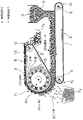
- FIG. 2 is an explanatory diagram showing an embodiment of the magnetic force sorting apparatus according to Embodiment 1 of the present invention and a magnetic force sorting method using this apparatus.
- the apparatus according to the first embodiment has a first belt conveyor A that transports the granular material a and a magnet that is positioned above the belt conveyor A and that has been transported by the belt conveyor A using a magnet.
- a second belt conveyor B that adsorbs and separates the magnetic particles is provided.
- the first belt conveyor A 1 is a conveyor belt
- 8 is a belt guide roll on the conveyor start end 14 side
- 9 is a belt guide roll on the conveyor end 10 side.
- the conveyor belt 1 is configured by installing the conveyor belt 1 between the belt guide rolls 8 and 9.
- the second belt conveyor B 2 is a conveyor belt
- 3 is a belt guide roll on the conveyor start end 11 side
- 13 is a belt guide roll on the conveyor end 12 side
- the conveyor belt 2 is between the belt guide rolls 3 and 13.
- the belt conveyor B is comprised by being installed in.
- the belt guide roll 3 is configured to have a larger diameter than the belt guide roll 13, and the rotation axis of the belt guide roll 13 is positioned higher than the rotation axis of the belt guide roll 3, so that the conveyor belt 2.
- the upper surface (the upper belt portion between the belt guide rolls 3 and 13) is substantially horizontal. However, the upper surface of the conveyor belt 2 may be lowered toward the belt guide roll 13.
- a supply device 6 for supplying powder particles a containing ferromagnetic particles on the conveyor belt 1 is disposed.
- the magnetic material recovery is performed below the conveyor terminal section 12 of the belt conveyor B.
- a portion 7x is provided.
- the non-magnetized substance collection unit 7y is provided at that position.
- the conveyor start end portion 11 of the belt conveyor B is located close to the conveyor end portion 10 of the belt conveyor A. Further, the belt guide rolls 8 and 9 of the belt conveyor A and the belt guide rolls 3 and 13 of the belt conveyor B are rotated in reverse to each other, and the conveyor terminal end 10 of the belt conveyor A and the conveyor start end 11 of the belt conveyor B.
- the conveyor belts 1 and 2 are moving in the same direction.
- the belt conveyor B may be a drive roll in which one of the belt guide rolls 3 and 13 is driven by a driving means such as a motor, but normally the belt guide roll 13 is a drive roll and the belt guide roll 3 is not driven. Become a roll.
- the belt guide roll 3 is composed of a hollow sleeve body and is rotatably supported.
- a magnet roll 4r is provided inside the belt guide roll 3 as a magnetic field applying means including a plurality of magnets 5.
- the magnet roll 4r is configured to be rotatable independently of the belt guide roll 3.
- a plurality of magnets 5 are arranged on the magnet roll 4r at predetermined intervals in the circumferential direction and the width direction of the belt guide roll 3.
- a plurality of magnets 5 are arranged so that adjacent magnetic poles are alternately N poles and S poles over the roll circumferential direction 360 ° C. of the magnet roll 4r.
- the several magnet 5 is distribute
- the magnet 5 is selected so that it is about 0.01 to 0.5 T at the conveyor belt portion in contact with the belt guide roll 3 according to the object. Is preferred. If the magnetic field is too weak, the effect of the magnet roll 4r cannot be sufficiently obtained. On the other hand, if the magnetic field is too strong, the attractive force acting on the ferromagnetic particles is too strong and the separation of the ferromagnetic particles may be hindered. There is.
- the magnetic field is switched from strong ⁇ weak ⁇ strong ⁇ weak ⁇ ...
- a plurality of magnets 5 arranged at a predetermined interval and a gap between adjacent magnets 5.
- the effect of aggregation ⁇ dispersion ⁇ aggregation ⁇ dispersion ⁇ ... Is repeated for the ferromagnetic particles in the granular layer.
- the width of the gap between the magnets 5 adjacent in the roll circumferential direction it is appropriate to set the width to about 1 to 50 mm in order to obtain the above effect.
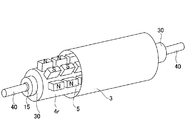
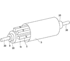
- FIG. 3 is a perspective view showing the structure of the belt guide roll of the magnetic separator according to Embodiment 1 of FIG. Inside the belt guide roll 3, a magnet roll 4r having a plurality of magnets is disposed.
- Reference numeral 40 denotes a roll shaft of the magnet roll 4r.
- the roll shafts 30 at both ends of the belt guide roll 3 are externally mounted on a roll shaft 40 of a magnet roll 4r disposed inside the belt guide roll 3, and the roll shaft is interposed via a bearing 15 (for example, a metal bearing or a bearing bearing). 40 is attached.
- the belt guide roll 3 and the magnet roll 4r can be independently rotated, and the forms of the roll shaft 30 and the roll shaft 40 can take various forms.
- the magnet roll 4r is a roll that is rotated by means such as a motor.
- the rotation direction of the magnet roll 4r may be the same as or opposite to that of the belt guide roll 3, but generally the rotation is opposite to that of the belt guide roll 3. It has become. Further, the magnet roll 4r rotates at a higher speed than the belt guide roll 3.
- the magnetic field change as fast as possible occurs.
- the magnet roll 4r defined by the following equation (1)
- the magnetic field change frequency F (Hz) is preferably 170 Hz or more. More preferably, the magnetic field change frequency is 200 Hz or more.
- a pair of (b) and N pole (c) counts as one magnetic pole, for example, a magnet having 12 poles in the circumferential direction (counted as one magnetic pole by a pair of N pole and S pole) (for example, a neodymium magnet) is provided.
- the rotation speed of the magnet roll 4r is 1000 rpm
- the magnetic field change frequency is 200 Hz
- a magnet having 24 poles in the circumferential direction counting as one magnetic pole for a pair of N poles and S poles
- the rotational speed of the magnet roll 4r is 500r. It may be m.
- the upper limit of the magnetic field change frequency is about 1000 Hz because there is a mechanical upper limit in the rotation speed of the magnet roll 4r and the effect of the magnetic field change may be saturated even if the frequency is increased.
- the size of the magnet 5 is not particularly limited as long as a predetermined number of magnets 5 can be arranged.
- the magnetic poles of one magnet 5 are arranged so as to be different on the inner peripheral side and the outer peripheral side of the magnet roll 4 r, but naturally different magnetic poles of one magnet 5 are magnets. You may install the magnet 5 so that it may rank with the circumferential direction of the roll 4r. Even in this case, since the N pole and the S pole are alternately provided, the ferromagnetic particles are efficiently separated.
- the N and S poles may be installed across the gap, and the N and S poles may be installed across the gap.
- the gap between the magnets 5 may be filled with resin or the like, and a cover may be attached to the outer periphery of the magnet roll 4r.
- the direction of rotation of the magnet roll 4r is the same as (i) the direction of travel of the conveyor belt 2 (the direction of rotation of the belt guide roll 3), and (ii) the direction of travel of the conveyor belt 2 (the direction of rotation of the belt guide roll 3). Either direction.
- the ferromagnetic particles are subjected to a transport force that tends to move in the direction opposite to the rotation direction of the magnet roll 4r by the action of the magnetic field of the rotating magnet roll 4r.
- the conveying force to the ferromagnetic particles by the magnetic field and the frictional force between the conveyor belt 2 and the ferromagnetic particles are in the same direction.
- the conveying force and the frictional force are in opposite directions. However, in this case, since the frictional force is larger, the ferromagnetic particles are transported in the traveling direction of the conveyor belt 2.
- the belt feeding speed of the conveyor belts 1 and 2 of the belt conveyors A and B may be set to a speed necessary for the processing process.
- the rotational speed of the magnet roll 4r is determined so that the change in the magnetic field is sufficiently high with respect to the belt feed speed.
- the rotational speed of the magnet roll 4r is preferably set so as to satisfy the condition of the above-described equation (1).
- the granular material a containing ferromagnetic particles is supplied from the supply device 6 onto the conveyor belt 1 that is moving the belt conveyor A with a sufficient thickness.
- the granular material a is conveyed to the conveyor terminal part 10.
- the granular material a conveyed by the conveyor belt 1 has its upper surface in contact with the lower surface of the conveyor starting end 11 of the belt conveyor B near the conveyor terminal 10, and the granular material a is in contact with the conveyor terminal 10 of the belt conveyor A.
- the belt conveys between the conveyor start end portions 11 of the belt conveyor B. At this time, the magnetic field of the magnetic field applying means 4 of the belt conveyor B is exerted on the granular material a.
- the belt conveyor is formed in such a manner that the ferromagnetic particles in the granular material a embed non-magnetic particles by the magnetic force of the magnet roll 4r as the magnetic field applying means 4. It adheres to the lower surface side of B and is carried by the conveyor belt 2.
- the ferromagnetic particles in the powder a are subjected to the action of the magnetic field of the magnet 5 provided in the magnet roll 4r, but the strength of the magnetic field is strong ⁇ weak ⁇ strong ⁇ weak ⁇ ... by the rotation of the magnet roll 4r. Switch instantly.
- the effect of aggregation ⁇ dispersion ⁇ aggregation ⁇ dispersion ⁇ ... Is repeated for the ferromagnetic particles in the granular layer.
- the magnetic field applying means is composed of the magnet roll 4r that rotates independently from the belt guide roll 3 as in the embodiment of FIG. 2, (1) mechanically high speed is achieved by rotating the magnet roll 4r. (2) Supplying granular material a with sufficient layer thickness in this changing magnetic field, (3) Entrainment / embracing of non-magnetic particles by ferromagnetic particles by magnetic field change , The ferromagnetic particles move to the magnet roll 4r side, and the non-magnetic particles are removed away from the magnet roll 4r. (4) The non-magnetic particles are the conveyor conveyor B end of the belt conveyor B As shown in FIG.
- the ferromagnetic particles fall by gravity at the section 11 and are carried while being adsorbed and held on the belt conveyor B, and discharged at the conveyor terminal section 12 of the belt conveyor B. Even if the granular material a supplied to the bare belt 1 is made sufficiently thick, the ferromagnetic particles can be efficiently magnetically selected. That is, the magnetic particles can be magnetically selected from the granular material a efficiently and quickly.
- the magnetic force sorting apparatus can efficiently sort the ferromagnetic particles from the granular material a. Therefore, in the magnetic force sorting of the granular material a using this device, As shown in FIG. 2, on the conveyor belt 1 of the belt conveyor A from the supply device 6, the particles have a layer thickness larger than the diameter of the smallest particles contained in the particles a and have a layer thickness at which the magnetic force acts sufficiently. It is desirable to feed the body. Specifically, the thickness of the granular material may be 20 to 30 mm.
- slag such as iron slag, iron ore tailing.
- iron slag iron slag
- iron ore tailing it is particularly suitable for magnetic selection of slag.
- iron slag is atomized. If the atomization is insufficient, the iron recovery rate is not improved.
- the particle size of the slag after atomization is determined according to the slag, but it is often necessary to atomize to about several tens of ⁇ m to 1 mm depending on the form of iron contained.
- pulverization is common. After grinding with jaw crusher or hammer crusher as coarse crushing, ball mill, rod mill, jet mill, pin mill (pin mill) for further pulverization ), Crush using an impact mill.
- magnetic field sorting is performed by the magnetic field sorting apparatus of the present invention for the atomized slag.
- iron can be efficiently separated and recovered from slag.
- the magnets 5 are arranged so that the magnetic poles of the portions facing the granular material a are the same over the width direction of the belt guide roll 3 (magnet roll 4r).
- the same magnetic poles are arranged in the width direction, a uniform magnetic field is formed and the force acting on the ferromagnetic particles is uniform, but if the magnets 5 are arranged so as to have different magnetic poles in the width direction, the magnetic field is not affected. It becomes uniform and a part where the ferromagnetic particles are not locally separated is formed, and the separation efficiency is lowered.
- the conveyor belt 2 and the belt guide roll 3 of the belt conveyor B of this embodiment are comprised with nonmetals, such as resin and a ceramic.
- the apparatus which concerns on this Embodiment 1 was provided in the inside of the belt guide roll 3 by the side of the conveyor starting end part 11 of the belt conveyor B to the granular material a (powder body layer) conveyed with the belt conveyor A.
- the ferromagnetic particles in the powder particles a are attracted and transferred to the lower surface side of the belt conveyor B to separate the ferromagnetic particles. Therefore, the distance between the conveyor terminal end 10 of the belt conveyor A and the conveyor start end 11 of the belt conveyor B may be a size that allows the magnetic force of the magnet roll 4r to sufficiently act on the ferromagnetic particles in the granular material a.
- the upper surface of the layer of the granular material a conveyed by the conveyor belt 1 of the belt conveyor A is in contact with the conveyor start end 11 of the belt conveyor B, that is, the granular material layer is the conveyor of the belt conveyor A. It is preferable that the size be such that it can be retracted between the end portion 10 and the conveyor start end portion 11 of the belt conveyor B.
- FIG. 4 is a diagram illustrating a magnetic force sorting apparatus according to the first modification of the first embodiment of the present invention.
- Modification 1 is such that the positional relationship between the belt conveyor A and the belt conveyor B is different from that shown in FIG. That is, the conveyor start end 11 of the belt conveyor B is located close to the conveyor terminal end 10 of the belt conveyor A, and the belt guide rolls 8 and 9 of the belt conveyor A and the belt guide roll 3 of the belt conveyor B, 13 is rotating in the same direction. Further, at the conveyor terminal portion 10 of the belt conveyor A and the conveyor start portion 11 of the belt conveyor B, the conveyor belts 1 and 2 are moving in the opposite directions.
- the ferromagnetic particles can be separated. Except for the positional relationship between the belt conveyors A and B, the configuration is substantially the same as that of the first embodiment shown in FIGS.
- FIG. 5 is an explanatory diagram showing a second modification of the magnetic force sorting apparatus according to Embodiment 1 of the present invention and a magnetic force sorting method using this apparatus.
- the belt guide roll 3 is formed of a hollow sleeve body and is rotatably supported. Inside the belt guide roll 3, magnetic field application means 4 having a plurality of magnets 5 arranged at predetermined intervals along the circumferential direction of the roll is provided.
- the magnetic field applying unit 4 of the second modification does not rotate.
- the magnet 5 of the magnetic field applying means 4 is a fixed magnet that is installed independently of the belt guide roll 3 and does not rotate.
- the magnets 5 of the magnetic field applying means 4 are arranged such that the adjacent magnetic poles are different in the roll circumferential direction, and the adjacent magnetic poles are the same in the roll width direction. Has been.
- the range in the roll circumferential direction where the magnet 5 is disposed is at least the lower end position of the belt guide roll 3 (opposite the conveyor terminal portion 10 of the belt conveyor A).
- the position of the belt guide roll 3 to the top position of the belt guide roll 3 is about 180 ° (half circumference of the belt guide roll 3). If the magnet 5 is fixed so as not to rotate as in the second embodiment, the range in which the magnet 5 is installed can be reduced.
- the ferromagnetic particles in the granular material a are attracted by the magnetic field applying means 4 having the fixed magnet 5 so that the ferromagnetic particles embrace the nonmagnetic particles.
- the granular material a adheres to (is held on) the lower surface side of the belt conveyor B and is conveyed by the conveyor belt 2.
- the effect is smaller than that of the magnet roll 4r in FIG.
- the ferromagnetic particles in the granular material a are affected by the magnetic force of the magnet 5 provided in the magnetic field applying means 4, and the conveyor belt 2 Since the magnetic field changes in the process of being carried by the strong ⁇ weak ⁇ strong ⁇ weak ⁇ ..., even for the ferromagnetic particles in the powder a, the set ⁇ dispersion ⁇ set ⁇ dispersion ⁇ ... Is repeated, and the same effect as that of the first embodiment shown in FIG. 2 is obtained. However, since the magnetic field does not change at high speed like the magnet roll 4r in FIG. 2, the magnetic force sorting performance and the processing speed are smaller than those in the first embodiment in FIG.
- the magnetic force sorting apparatus applies (i) a magnetic field applied by the magnetic field applying means 4 included in the second belt conveyor B to the powder a discharged from the first belt conveyor A from above. Since the basic method of adsorbing and moving the ferromagnetic material contained in the granular material a to the belt conveyor B side is adopted, the inclusion of non-magnetic material particles by the ferromagnetic particles is less than that of the conventional device. (Ii) Furthermore, the effect of eliminating the entrainment / embracing of nonmagnetic particles by the ferromagnetic particles by the magnetic field change by the magnetic field applying means 4 can be obtained.
- FIG. 6 is a perspective view showing the structure of the belt guide roll of Modification 3 of the magnetic force sorting apparatus according to Embodiment 1 of FIG.
- a plurality of magnets 5 installed on the magnet roll 4r are provided along the circumferential direction of the belt guide roll 3 (magnet roll 4r), and the belt Only one guide roll 3 (magnet roll 4r) is provided in the width direction.
- the magnets 5 are arranged along the circumferential direction so that the magnetic poles facing the powder particles a are alternately arranged. In this way, the magnet 5 may be configured.
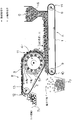
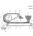
- FIG. 7 is an explanatory view showing one embodiment of the magnetic force sorting apparatus of the second embodiment and a magnetic force sorting method using this apparatus.
- the magnetic force sorting apparatus is a belt conveyor type magnetic sorting apparatus.
- the magnetic force sorting apparatus supplies the granular material a containing ferromagnetic particles from the supply device onto the conveyor belt 201, and when the granular material a is discharged from the conveyor terminal end 2010, the magnetic force is applied.
- the ferromagnetic particles are attracted and separated from the non-magnetic particles.
- 201 is a conveyor belt
- 202 is a belt guide roll on the conveyor end portion 2010 side
- 208 is a belt guide roll on the conveyor start end portion 2011 side.
- a conveyor belt 201 is configured by installing the conveyor belt 201 between the belt guide rolls 202 and 208.
- the belt conveyor rotates the conveyor belt 201 when the belt guide roll 208 is driven by driving means such as a motor.
- the belt guide roll 202 is a non-driving roll, and is constituted by a sleeve body having a hollow inside.
- a magnet roll 203 is disposed inside the belt guide roll 202.
- the configuration of the magnet roll 203 is substantially the same as the configuration shown in FIG.
- the magnet roll 203 includes a plurality of magnets 205 arranged at predetermined intervals in the circumferential direction and the width direction, and the magnetic poles of the magnets 205 adjacent in the roll circumferential direction are different magnetic poles (N Pole, S pole). That is, the magnet 205 is disposed so that the N pole and the S pole are alternately arranged in the roll circumferential direction.
- the plurality of magnets 205 are arranged to have the same magnetic pole in the width direction of the roll.
- the magnet roll 203 is a roll that is rotated by a motor or the like, and is rotated in the opposite direction to the belt guide roll 202. Further, as will be described later, the magnet roll 203 rotates at a higher speed than the belt guide roll 202.
- the members around the rotating magnet roll are affected by the eddy current effect due to the changing magnetic field, and the metal member is heated by the eddy current even if it is a non-magnetic material.
- the conveyor belt 201 and the belt guide roll 202 are comprised with nonmetals, such as resin and a ceramic.
- the magnet 205 is arrange
- FIG. In the case of the same magnetic pole in the width direction, a uniform magnetic field is formed and the force acting on the ferromagnetic particles is also uniform. However, if the magnets 205 of different magnetic poles are arranged in the width direction, the magnetic field becomes non-uniform and locally A portion where the ferromagnetic particles are not separated is formed, and the separation efficiency is lowered.
- the magnet 205 may be a single magnet arranged in the width direction as shown in FIG. 6 or may be appropriately divided as shown in FIG.
- the magnetic field of the magnet roll 203 defined by the following equation (1)
- the change frequency F (Hz) is preferably 170 Hz or more. More preferably, the magnetic field change frequency is 200 Hz or more.
- the N pole (a), the S pole (b), and the N pole (c) are arranged in the circumferential direction, one pair of the N pole (a) and the S pole (b), one S pole ( A pair of b) and N pole (c) counts as one magnetic pole.
- a magnet for example, a neodymium magnet
- the rotation speed of the magnet roll 203 is 1000 rpm, the magnetic field changes.
- the frequency is 200 Hz.
- the rotational speed of the magnet roll 203 may be 500 rpm.
- the upper limit of the magnetic field change frequency is about 1000 Hz because the rotational speed of the magnet roll 203 has a mechanical upper limit, and even if the frequency is increased, the effect of the magnetic field change may be saturated.
- the size of the magnet 205 is not particularly limited as long as a predetermined number of magnets can be arranged. Although there is no particular limitation on the strength of the magnetic field by the magnet 205, the magnet 205 is usually selected so that it is about 0.01 to 0.5 T at the conveyor belt portion in contact with the belt guide roll 202 depending on the object. Is preferred. If the magnetic field is too weak, the effect of the magnet roll 203 cannot be obtained sufficiently. On the other hand, if the magnetic field is too strong, the attractive force acting on the ferromagnetic particles is too strong, and the separation of the ferromagnetic particles according to the above-described principle (FIGS. 1A to 1D) may be hindered. .
- the strength of the magnetic field is instantaneously switched from strong ⁇ weak ⁇ strong ⁇ weak ⁇ ... It is characterized in that the effect of aggregation ⁇ dispersion ⁇ aggregation ⁇ dispersion ⁇ ... Is repeatedly obtained for the ferromagnetic particles in the granular layer.
- the width of the gap between the adjacent magnets 205 in the roll circumferential direction is no particular limitation, but a state in which the ferromagnetic particles in the powder layer are appropriately released from the magnetic field, Usually, about 1 to 50 mm is appropriate so that the magnetic field weakening state does not last too long.
- a partition plate 6 is disposed below (directly below) the belt guide roll 202 along the conveyor belt width direction, and the upper end of the partition plate 206 and the conveyor belt 201 (the movement direction is reversed by the belt guide roll 202).
- a gap S for allowing the ferromagnetic particles to pass therethrough is provided between the conveyor belt portion).
- the reason why the partition plate 206 is provided in such a form is that the falling area of the non-magnetic particles and the falling area of the ferromagnetic particles are adjacent to each other, so that both particles do not mix during the dropping.
- a magnetized material recovery unit 207x and a non-magnetized material recovery unit 207y are provided at a position sandwiching the partition plate 206 in the conveyor belt moving direction. That is, the magnetized material recovery unit 207x is not positioned at the position on the conveyor starting end 2011 side (ferromagnetic particle falling area) across the partition plate 206, and is not positioned at the position on the conveyor terminal end 2010 side (non-magnetic particle falling area).
- a magnetic deposit collection unit 207y is provided.
- the belt feed speed of the conveyor belt 201 (rotational speed of the belt guide rolls 202 and 208) may be set to a speed necessary for the processing process.
- the rotation speed of the magnet roll 203 is determined so that the change in the magnetic field is sufficiently high with respect to the belt feed speed.
- the rotational speed of the magnet roll 203 is preferably set so as to satisfy the condition of the above-described equation (1).
- the granular material a containing ferromagnetic particles is supplied from the supply device 204 onto the operating conveyor belt 201 with a sufficient thickness, and is conveyed to the conveyor terminal portion 2010 (positions of the belt guide roll 202 and the magnet roll 203). Is done. And when the granular material a on the conveyor belt 201 is discharged
- the granular material a is sent along the arc of the belt guide roll 202 as the conveyor belt 201 moves, but the non-magnetic particles are gravity in the range of 1/4 to 1/2 rotation. Free fall by.
- the ferromagnetic particles have a small mass due to atomization and have a sufficiently large magnetic field, so that they are immediately attracted to the magnet even when dropped from the conveyor belt 201.
- the ferromagnetic particles are sent in the traveling direction of the conveyor belt 201, and fall free when they are out of the magnetic field area by more than 1/2 rotation.
- the partition plate 206 prevents the non-magnetic particles and the ferromagnetic particles from being mixed. Note that the position of the partition plate 206 may be adjusted according to the feed speed of the conveyor belt 201 and the dropping behavior of the granular material a.
- the magnets 5 are arranged so that the magnetic poles facing the granular material a are the same over the width direction of the belt guide roll 3 (magnet roll 4r). Thereby, a uniform magnetic field is formed in the width direction, and the magnetic force acting on the ferromagnetic particles is uniform.
- a magnetically high-speed magnetic field change is generated by rotating the magnet roll 203, and (ii) a sufficient layer thickness is provided within the changing magnetic field.
- the ferromagnetic particles move to the magnet roll 203 side while eliminating the entrainment / embracing of the non-magnetic particles by the ferromagnetic particles due to the magnetic field change, and the non-magnetic particles are supplied. Is removed to the side farther from the magnet roll 203.
- Non-magnetic particles fall by gravity under the belt guide roll 202, and the ferromagnetic particles remain adsorbed and held on the conveyor belt 201 side.
- the layer thickness of the granular material a supplied to the conveyor belt 201 is sufficiently thick as shown in FIG. 7 by the action of being carried and dropping when the influence of the magnetic field disappears, the ferromagnetic material is efficiently obtained.
- Child can be screened magnetic force. That is, the magnetic particles can be magnetically selected from the granular material a efficiently and quickly.
- the rotational speed of the magnet roll 203 can be adjusted so that appropriate performance can be obtained.
- the magnetic force sorting apparatus of the second embodiment can efficiently sort the ferromagnetic particles from the powder a as described above, in the magnetic force sorting of the powder a using the apparatus, FIG. 7, the granular material is supplied from the supply device 204 onto the conveyor belt 201 with a layer thickness larger than the diameter of the minimum particle included in the granular material a and with a layer thickness at which a magnetic field sufficiently acts. Is desirable. Specifically, the thickness of the granular material may be 20 to 30 mm.
- the gap S between the upper end portion of the partition plate 206 and the conveyor belt 201 is smaller than the layer thickness of the granular material a supplied from the supply device 204 onto the conveyor belt 201.
- the purpose of installing the partition plate 206 is as described above.
- the partition plate 206 is used. It is desirable that the upper end of the belt be as close as possible to the conveyor belt 201. Specifically, if the gap S is made smaller than the layer thickness of the granular material a, mixing of ferromagnetic particles and nonmagnetic particles can be prevented.
- slag such as iron slag, iron ore tailing, and the like.
- iron slag iron ore tailing
- it is particularly suitable for magnetic selection of slag.
- iron slag is atomized. If the atomization is insufficient, the iron recovery rate is not improved.
- steelmaking and steelmaking processes that generate steelmaking slag, and the generated slag is also diverse.
- the particle size of the slag after atomization is determined according to the slag, but it is often necessary to atomize to about several tens of ⁇ m to 1 mm depending on the form of iron contained.
- pulverization is common. After coarsely pulverized with a jaw crusher or a Hanmark crusher, further pulverized using a ball mill, rod mill, jet mill, pin mill, impact mill or the like for finer pulverization.
- a vortex sorter with a seemingly similar structure is known as a sorter for ferromagnetic materials, but there is a difference in the principle of sorting metal particles.
- a mechanism for adjusting the position according to the size of the metal particles to be collected is required, and a space for that is also required.
- such a position adjustment of the collection case is unnecessary, and therefore, a complicated mechanism for that purpose is also unnecessary.
- the present invention is not limited to the sorting apparatus and sorting method of the first and second embodiments as described above, and various design changes can be implemented. Moreover, it can also implement as a manufacturing method of the iron source which manufactures an iron source from the by-product of an iron manufacturing process using the magnetic force selection method of Embodiment 1 and 2.
- the slag that passed through the sieve mesh was used as the target granular material for magnetic sorting.
- the iron concentration of this granular material was 54 mass%.
- the supply layer thickness of the granular material on the conveyor belt 1 of the belt conveyor A was 7 mm.
- the outer diameter of the belt guide roll 3 of the belt conveyor B is 300 mm
- the number of magnetic poles of the magnet roll 4r is 12 poles (however, one pole is a pair of N poles and S poles)
- the conveyor belts 1 of the belt conveyors A and B The feed speed of 2 was 0.5 m / s
- the rotation speed of the belt guide roll 3 was 31.9 rpm
- the magnetic field strength at the conveyor belt portion in contact with the belt guide roll 3 was 0.2 T.
- the magnetically collected material of Comparative Example 1 using the drum magnetic separator A has a low iron concentration because it contains a non-ferrous component, and also has a low iron recovery rate because iron has escaped to the non-magnetic side.
- Comparative Example 2 using the pulley magnetic separator B since almost all of the granular material was entrained, the iron recovery rate is certainly good, but the iron concentration of the magnetically recovered material is the powder before the magnetic selection. It is almost the same as a granule.
- the magnetic field change frequency of the magnet roll 3 is set to 170 Hz or higher, both the iron concentration of the magnetically collected material and the iron recovery rate of the slag are obtained. If the magnetic field change frequency is 200 Hz or more, a higher value can be obtained for both the iron concentration of the magnetically collected material and the iron recovery rate of the slag.
- the slag that passed through the sieve mesh was used as the target granular material for magnetic sorting.
- the iron concentration of this granular material was 54 mass%.
- the thickness of the supply layer of the granular material on the conveyor belt 201 was 7 mm.
- the outer diameter of the belt guide roll 202 is 300 mm
- the number of magnetic poles of the magnet roll 203 is 12 poles (however, one pole is a pair of N poles and S poles)
- the feed speed of the conveyor belt 201 is 0.5 m / s
- the belt The rotational speed of the guide roll 202 was 31.9 rpm
- the magnetic field strength at the conveyor belt portion in contact with the belt guide roll 202 was 0.2T.
- the magnetically collected material of Comparative Example 1 using the drum magnetic separator A has a low iron concentration because it contains a non-ferrous component, and also has a low iron recovery rate because iron is released to the non-magnetic side.
- Comparative Example 2 using the pulley magnetic separator B since almost the entire amount of the granular material was entrained, the recovery rate is surely good, but the iron concentration of the magnetically collected magnetic substance is the powder particle before the magnetic selection. Almost the same as the body.
- the magnetic field change frequency of the magnet roll 203 is set to 170 Hz or more, high values are obtained for both the iron concentration of the magnetically collected material and the iron recovery rate of the slag. If the magnetic field change frequency is 200 Hz or more, a higher value can be obtained for both the iron concentration of the magnetically collected material and the iron recovery rate of the slag.
Landscapes
- Sorting Of Articles (AREA)
- Combined Means For Separation Of Solids (AREA)
- Belt Conveyors (AREA)
- Electrostatic Separation (AREA)
Priority Applications (6)
| Application Number | Priority Date | Filing Date | Title |
|---|---|---|---|
| EP13846992.9A EP2910309B1 (en) | 2012-10-16 | 2013-10-11 | Magnetic sorting apparatus, magnetic sorting method, and method for manufacturing iron source |
| CN201380054216.XA CN104736249A (zh) | 2012-10-16 | 2013-10-11 | 磁力分选装置、磁力分选方法及铁源的制造方法 |
| JP2014541943A JP5773089B2 (ja) | 2012-10-16 | 2013-10-11 | 磁力選別装置、磁力選別方法および鉄源の製造方法 |
| IN483MUN2015 IN2015MN00483A (enExample) | 2012-10-16 | 2013-10-11 | |
| KR1020187009294A KR102023543B1 (ko) | 2012-10-16 | 2013-10-11 | 자력 선별 장치, 자력 선별 방법 및 철원의 제조 방법 |
| KR1020157010330A KR20150058475A (ko) | 2012-10-16 | 2013-10-11 | 자력 선별 장치, 자력 선별 방법 및 철원의 제조 방법 |
Applications Claiming Priority (4)
| Application Number | Priority Date | Filing Date | Title |
|---|---|---|---|
| JP2012-229210 | 2012-10-16 | ||
| JP2012229214 | 2012-10-16 | ||
| JP2012229210 | 2012-10-16 | ||
| JP2012-229214 | 2012-10-16 |
Publications (1)
| Publication Number | Publication Date |
|---|---|
| WO2014061256A1 true WO2014061256A1 (ja) | 2014-04-24 |
Family
ID=50487835
Family Applications (1)
| Application Number | Title | Priority Date | Filing Date |
|---|---|---|---|
| PCT/JP2013/006109 Ceased WO2014061256A1 (ja) | 2012-10-16 | 2013-10-11 | 磁力選別装置、磁力選別方法および鉄源の製造方法 |
Country Status (6)
| Country | Link |
|---|---|
| EP (1) | EP2910309B1 (enExample) |
| JP (1) | JP5773089B2 (enExample) |
| KR (2) | KR20150058475A (enExample) |
| CN (2) | CN111229460A (enExample) |
| IN (1) | IN2015MN00483A (enExample) |
| WO (1) | WO2014061256A1 (enExample) |
Cited By (13)
| Publication number | Priority date | Publication date | Assignee | Title |
|---|---|---|---|---|
| US20130186807A1 (en) * | 2012-01-24 | 2013-07-25 | GM Global Technology Operations LLC | Magnetic separator system and method using spatially modulated magnetic fields |
| CN104722399A (zh) * | 2015-01-22 | 2015-06-24 | 包头市金蒙汇磁材料有限责任公司 | 一种分离稀土永磁材料中杂质的磁选机 |
| JP2016014184A (ja) * | 2014-07-03 | 2016-01-28 | 株式会社神戸製鋼所 | 金属鉄の製造方法 |
| CN106076618A (zh) * | 2016-08-07 | 2016-11-09 | 李勇军 | 微型永磁辊 |
| WO2017094803A1 (ja) * | 2015-11-30 | 2017-06-08 | Jfeスチール株式会社 | 磁力選別装置、磁力選別方法および鉄源の製造方法 |
| JP2017131869A (ja) * | 2016-01-29 | 2017-08-03 | Jfeスチール株式会社 | 磁力選別装置および磁力選別方法 |
| JP2018086603A (ja) * | 2016-11-28 | 2018-06-07 | Jfeスチール株式会社 | 粒状物の磁力選別方法及び装置 |
| JP2018090477A (ja) * | 2016-11-29 | 2018-06-14 | Jfeスチール株式会社 | 鉄鋼スラグの処理方法 |
| JP2018109229A (ja) * | 2016-12-29 | 2018-07-12 | Jfeスチール株式会社 | 鉄鋼スラグの処理方法 |
| JP2018122219A (ja) * | 2017-01-31 | 2018-08-09 | Jfeスチール株式会社 | 磁力選別装置 |
| JP2019099838A (ja) * | 2017-11-29 | 2019-06-24 | Jfeスチール株式会社 | 鉄鋼スラグの処理方法 |
| JP2019127647A (ja) * | 2018-01-26 | 2019-08-01 | Jfeスチール株式会社 | 鉄鋼スラグから分離される鉄原料の製造方法 |
| CN115193581A (zh) * | 2021-04-09 | 2022-10-18 | 新沂市中大石英科技有限公司 | 一种石英砂的高效磁选机 |
Families Citing this family (13)
| Publication number | Priority date | Publication date | Assignee | Title |
|---|---|---|---|---|
| JP6252712B2 (ja) * | 2015-08-12 | 2017-12-27 | 宇部興産株式会社 | 樹脂ペレットの選別方法、蓄電デバイス用セパレータ及び樹脂粉粒体群 |
| CN105413858A (zh) * | 2016-01-11 | 2016-03-23 | 潘静娴 | 一种利用微小磁极距形成高密度磁峰值的磁选装置 |
| CN105689117B (zh) * | 2016-02-05 | 2018-06-01 | 鄂尔多斯市君致清环境科技有限公司 | 一种浓缩磁选机及基于该浓缩磁选机的浓缩方法 |
| CN105964398B (zh) * | 2016-05-20 | 2019-01-25 | 湖南三德科技股份有限公司 | 一种用于样品输送系统的除铁装置 |
| US10625946B2 (en) * | 2016-06-30 | 2020-04-21 | Shounan Engineering Inc. | Magnetic chip conveyor |
| DE102016013486B3 (de) | 2016-11-11 | 2018-01-04 | Admedes Schuessler Gmbh | Flechtmaschine und Weiche für eine Flechtmaschine |
| CN107597425A (zh) * | 2017-08-25 | 2018-01-19 | 太湖县光华铝业有限公司 | 连续作业式再生铝颗粒分选装置 |
| CN109433414B (zh) * | 2018-12-20 | 2020-04-07 | 清华苏州环境创新研究院 | 涡电流分选机装置 |
| CN110641755B (zh) * | 2019-10-30 | 2024-09-06 | 厦门佰顺兴自动化科技有限公司 | 一种多晶硅表金属去除装置 |
| KR102298216B1 (ko) * | 2019-11-19 | 2021-09-30 | 주식회사 카비 | 와전류를 이용한 비철금속 선별장치 |
| KR102285136B1 (ko) * | 2019-11-29 | 2021-08-05 | 한국생산기술연구원 | 레이저 적층공정에서 회수된 금속분말 분류장치 |
| US11590512B2 (en) * | 2020-02-28 | 2023-02-28 | Sintokogio, Ltd. | Magnetic separating apparatus and magnetic sorting method |
| KR20240026821A (ko) | 2022-08-22 | 2024-02-29 | 강두석 | 쇳가루 회수유닛을 이용한 분체풀림장치 |
Citations (4)
| Publication number | Priority date | Publication date | Assignee | Title |
|---|---|---|---|---|
| JPH10130041A (ja) | 1996-10-28 | 1998-05-19 | Furukawa Co Ltd | スラグの分離回収方法及び分離回収設備 |
| JP2006142136A (ja) | 2004-11-16 | 2006-06-08 | Ishikawajima Harima Heavy Ind Co Ltd | スラグ中の異物除去方法及び装置 |
| JP2008104915A (ja) * | 2006-10-24 | 2008-05-08 | Osaka Magunetsutoroole Seisakusho:Kk | アルミニウム選別装置 |
| JP2011104583A (ja) * | 2009-10-22 | 2011-06-02 | Jfe Steel Corp | 強磁性体の分離装置 |
Family Cites Families (10)
| Publication number | Priority date | Publication date | Assignee | Title |
|---|---|---|---|---|
| JPS5468571A (en) * | 1977-11-11 | 1979-06-01 | Mitsubishi Electric Corp | Magnetic sorter |
| KR0179027B1 (ko) * | 1991-07-25 | 1999-03-20 | 스즈끼 아끼오 | 비자성 금속 분리 벨트 컨베이어 |
| CN1100622C (zh) * | 1996-03-25 | 2003-02-05 | 丸起有限会社 | 非磁性金属空罐的分选装置 |
| DE19838170C2 (de) * | 1998-08-21 | 2001-06-07 | Meier Staude Robert | Verfahren und Vorrichtung zur Wirbelstromscheidung von Materialgemischen in Teilchenform |
| CN200981018Y (zh) * | 2006-06-20 | 2007-11-28 | 北京雪域火磁电设备技术有限公司 | 一种细碎物料干式磁选机 |
| CN200998691Y (zh) * | 2006-11-22 | 2008-01-02 | 蒋兴旺 | 从炼铁产生的烟灰中干选分离出磁铁矿的设备 |
| CN200977475Y (zh) * | 2006-11-22 | 2007-11-21 | 魏传富 | 旋转磁场干选机 |
| KR101269151B1 (ko) * | 2011-03-15 | 2013-05-29 | 재단법인 포항산업과학연구원 | 마그네틱 드럼을 이용한 자력 선별장치 |
| CN202087414U (zh) * | 2011-03-29 | 2011-12-28 | 北京矿冶研究总院 | 粗颗粒磁铁矿干式磁选设备 |
| CN202538925U (zh) * | 2012-03-08 | 2012-11-21 | 陈靓 | 快速磁翻转高场强磁滚筒 |
-
2013
- 2013-10-11 WO PCT/JP2013/006109 patent/WO2014061256A1/ja not_active Ceased
- 2013-10-11 JP JP2014541943A patent/JP5773089B2/ja active Active
- 2013-10-11 CN CN202010070551.0A patent/CN111229460A/zh active Pending
- 2013-10-11 CN CN201380054216.XA patent/CN104736249A/zh active Pending
- 2013-10-11 EP EP13846992.9A patent/EP2910309B1/en active Active
- 2013-10-11 KR KR1020157010330A patent/KR20150058475A/ko not_active Ceased
- 2013-10-11 KR KR1020187009294A patent/KR102023543B1/ko active Active
- 2013-10-11 IN IN483MUN2015 patent/IN2015MN00483A/en unknown
Patent Citations (4)
| Publication number | Priority date | Publication date | Assignee | Title |
|---|---|---|---|---|
| JPH10130041A (ja) | 1996-10-28 | 1998-05-19 | Furukawa Co Ltd | スラグの分離回収方法及び分離回収設備 |
| JP2006142136A (ja) | 2004-11-16 | 2006-06-08 | Ishikawajima Harima Heavy Ind Co Ltd | スラグ中の異物除去方法及び装置 |
| JP2008104915A (ja) * | 2006-10-24 | 2008-05-08 | Osaka Magunetsutoroole Seisakusho:Kk | アルミニウム選別装置 |
| JP2011104583A (ja) * | 2009-10-22 | 2011-06-02 | Jfe Steel Corp | 強磁性体の分離装置 |
Non-Patent Citations (2)
| Title |
|---|
| J. SVOBODA: "Magnetic Techniques for the Treatment of Materials", 2004, KLUWER ACADEMIC PUBLISHERS, pages: 70 - 72 |
| See also references of EP2910309A4 |
Cited By (18)
| Publication number | Priority date | Publication date | Assignee | Title |
|---|---|---|---|---|
| US9289778B2 (en) * | 2012-01-24 | 2016-03-22 | GM Global Technology Operations LLC | Magnetic separator system and method using spatially modulated magnetic fields |
| US20130186807A1 (en) * | 2012-01-24 | 2013-07-25 | GM Global Technology Operations LLC | Magnetic separator system and method using spatially modulated magnetic fields |
| JP2016014184A (ja) * | 2014-07-03 | 2016-01-28 | 株式会社神戸製鋼所 | 金属鉄の製造方法 |
| CN104722399A (zh) * | 2015-01-22 | 2015-06-24 | 包头市金蒙汇磁材料有限责任公司 | 一种分离稀土永磁材料中杂质的磁选机 |
| US20180353969A1 (en) * | 2015-11-30 | 2018-12-13 | Jfe Steel Corporation | Magnetic separator, magnetic separation method, and iron source manufacturing method |
| WO2017094803A1 (ja) * | 2015-11-30 | 2017-06-08 | Jfeスチール株式会社 | 磁力選別装置、磁力選別方法および鉄源の製造方法 |
| WO2017094039A1 (ja) * | 2015-11-30 | 2017-06-08 | Jfeスチール株式会社 | 磁力選別装置、磁力選別方法および鉄源の製造方法 |
| JPWO2017094803A1 (ja) * | 2015-11-30 | 2017-11-30 | Jfeスチール株式会社 | 磁力選別装置、磁力選別方法および鉄源の製造方法 |
| US10857548B2 (en) | 2015-11-30 | 2020-12-08 | Jfe Steel Corporation | Magnetic separator, magnetic separation method, and iron source manufacturing method |
| JP2017131869A (ja) * | 2016-01-29 | 2017-08-03 | Jfeスチール株式会社 | 磁力選別装置および磁力選別方法 |
| CN106076618A (zh) * | 2016-08-07 | 2016-11-09 | 李勇军 | 微型永磁辊 |
| JP2018086603A (ja) * | 2016-11-28 | 2018-06-07 | Jfeスチール株式会社 | 粒状物の磁力選別方法及び装置 |
| JP2018090477A (ja) * | 2016-11-29 | 2018-06-14 | Jfeスチール株式会社 | 鉄鋼スラグの処理方法 |
| JP2018109229A (ja) * | 2016-12-29 | 2018-07-12 | Jfeスチール株式会社 | 鉄鋼スラグの処理方法 |
| JP2018122219A (ja) * | 2017-01-31 | 2018-08-09 | Jfeスチール株式会社 | 磁力選別装置 |
| JP2019099838A (ja) * | 2017-11-29 | 2019-06-24 | Jfeスチール株式会社 | 鉄鋼スラグの処理方法 |
| JP2019127647A (ja) * | 2018-01-26 | 2019-08-01 | Jfeスチール株式会社 | 鉄鋼スラグから分離される鉄原料の製造方法 |
| CN115193581A (zh) * | 2021-04-09 | 2022-10-18 | 新沂市中大石英科技有限公司 | 一种石英砂的高效磁选机 |
Also Published As
| Publication number | Publication date |
|---|---|
| CN111229460A (zh) | 2020-06-05 |
| EP2910309A4 (en) | 2016-01-20 |
| EP2910309A1 (en) | 2015-08-26 |
| KR102023543B1 (ko) | 2019-09-20 |
| KR20150058475A (ko) | 2015-05-28 |
| JP5773089B2 (ja) | 2015-09-02 |
| JPWO2014061256A1 (ja) | 2016-09-05 |
| IN2015MN00483A (enExample) | 2015-09-11 |
| CN104736249A (zh) | 2015-06-24 |
| EP2910309B1 (en) | 2022-07-27 |
| KR20180035951A (ko) | 2018-04-06 |
Similar Documents
| Publication | Publication Date | Title |
|---|---|---|
| JP5773089B2 (ja) | 磁力選別装置、磁力選別方法および鉄源の製造方法 | |
| JP6399203B2 (ja) | 磁力選別装置、磁力選別方法および鉄源の製造方法 | |
| US9010538B2 (en) | Apparatus and method for magnetic separation | |
| JP6638719B2 (ja) | 鉄鋼スラグの処理方法 | |
| KR101354982B1 (ko) | 강자성체의 분리 장치 | |
| JP6702293B2 (ja) | 鉄鋼スラグの処理方法 | |
| US20140367312A1 (en) | Apparatus and a method for sorting a particulate material | |
| JP6690565B2 (ja) | 磁力選別方法及び装置 | |
| CN202087414U (zh) | 粗颗粒磁铁矿干式磁选设备 | |
| JP6394619B2 (ja) | 磁力選別装置および磁力選別方法 | |
| JP6760246B2 (ja) | 鉄鋼スラグの処理方法 | |
| JP6056617B2 (ja) | 強磁性体の分離方法及び装置 | |
| JP6870625B2 (ja) | 鉄鋼スラグから分離される鉄原料の製造方法 | |
| JP6984625B2 (ja) | 鉄鋼スラグの処理方法 | |
| JP2014200724A (ja) | 強磁性体の分離方法及び装置 | |
| JP2014079698A (ja) | 磁力選別方法及び磁力選別設備 |
Legal Events
| Date | Code | Title | Description |
|---|---|---|---|
| 121 | Ep: the epo has been informed by wipo that ep was designated in this application |
Ref document number: 13846992 Country of ref document: EP Kind code of ref document: A1 |
|
| ENP | Entry into the national phase |
Ref document number: 2014541943 Country of ref document: JP Kind code of ref document: A |
|
| NENP | Non-entry into the national phase |
Ref country code: DE |
|
| ENP | Entry into the national phase |
Ref document number: 20157010330 Country of ref document: KR Kind code of ref document: A |
|
| WWE | Wipo information: entry into national phase |
Ref document number: 2013846992 Country of ref document: EP |