WO2014054561A1 - Joint - Google Patents
Joint Download PDFInfo
- Publication number
- WO2014054561A1 WO2014054561A1 PCT/JP2013/076493 JP2013076493W WO2014054561A1 WO 2014054561 A1 WO2014054561 A1 WO 2014054561A1 JP 2013076493 W JP2013076493 W JP 2013076493W WO 2014054561 A1 WO2014054561 A1 WO 2014054561A1
- Authority
- WO
- WIPO (PCT)
- Prior art keywords
- gasket
- seal portion
- easily deformable
- thin
- plate
- Prior art date
Links
Images


Classifications
-
- F—MECHANICAL ENGINEERING; LIGHTING; HEATING; WEAPONS; BLASTING
- F16—ENGINEERING ELEMENTS AND UNITS; GENERAL MEASURES FOR PRODUCING AND MAINTAINING EFFECTIVE FUNCTIONING OF MACHINES OR INSTALLATIONS; THERMAL INSULATION IN GENERAL
- F16L—PIPES; JOINTS OR FITTINGS FOR PIPES; SUPPORTS FOR PIPES, CABLES OR PROTECTIVE TUBING; MEANS FOR THERMAL INSULATION IN GENERAL
- F16L19/00—Joints in which sealing surfaces are pressed together by means of a member, e.g. a swivel nut, screwed on or into one of the joint parts
- F16L19/02—Pipe ends provided with collars or flanges, integral with the pipe or not, pressed together by a screwed member
- F16L19/0212—Pipe ends provided with collars or flanges, integral with the pipe or not, pressed together by a screwed member using specially adapted sealing means
- F16L19/0225—Pipe ends provided with collars or flanges, integral with the pipe or not, pressed together by a screwed member using specially adapted sealing means without sealing rings
-
- F—MECHANICAL ENGINEERING; LIGHTING; HEATING; WEAPONS; BLASTING
- F16—ENGINEERING ELEMENTS AND UNITS; GENERAL MEASURES FOR PRODUCING AND MAINTAINING EFFECTIVE FUNCTIONING OF MACHINES OR INSTALLATIONS; THERMAL INSULATION IN GENERAL
- F16J—PISTONS; CYLINDERS; SEALINGS
- F16J15/00—Sealings
- F16J15/02—Sealings between relatively-stationary surfaces
- F16J15/06—Sealings between relatively-stationary surfaces with solid packing compressed between sealing surfaces
- F16J15/10—Sealings between relatively-stationary surfaces with solid packing compressed between sealing surfaces with non-metallic packing
- F16J15/104—Sealings between relatively-stationary surfaces with solid packing compressed between sealing surfaces with non-metallic packing characterised by structure
-
- F—MECHANICAL ENGINEERING; LIGHTING; HEATING; WEAPONS; BLASTING
- F16—ENGINEERING ELEMENTS AND UNITS; GENERAL MEASURES FOR PRODUCING AND MAINTAINING EFFECTIVE FUNCTIONING OF MACHINES OR INSTALLATIONS; THERMAL INSULATION IN GENERAL
- F16J—PISTONS; CYLINDERS; SEALINGS
- F16J15/00—Sealings
- F16J15/02—Sealings between relatively-stationary surfaces
- F16J15/021—Sealings between relatively-stationary surfaces with elastic packing
- F16J15/022—Sealings between relatively-stationary surfaces with elastic packing characterised by structure or material
-
- F—MECHANICAL ENGINEERING; LIGHTING; HEATING; WEAPONS; BLASTING
- F16—ENGINEERING ELEMENTS AND UNITS; GENERAL MEASURES FOR PRODUCING AND MAINTAINING EFFECTIVE FUNCTIONING OF MACHINES OR INSTALLATIONS; THERMAL INSULATION IN GENERAL
- F16J—PISTONS; CYLINDERS; SEALINGS
- F16J15/00—Sealings
- F16J15/02—Sealings between relatively-stationary surfaces
- F16J15/06—Sealings between relatively-stationary surfaces with solid packing compressed between sealing surfaces
- F16J15/061—Sealings between relatively-stationary surfaces with solid packing compressed between sealing surfaces with positioning means
-
- F—MECHANICAL ENGINEERING; LIGHTING; HEATING; WEAPONS; BLASTING
- F16—ENGINEERING ELEMENTS AND UNITS; GENERAL MEASURES FOR PRODUCING AND MAINTAINING EFFECTIVE FUNCTIONING OF MACHINES OR INSTALLATIONS; THERMAL INSULATION IN GENERAL
- F16J—PISTONS; CYLINDERS; SEALINGS
- F16J15/00—Sealings
- F16J15/02—Sealings between relatively-stationary surfaces
- F16J15/06—Sealings between relatively-stationary surfaces with solid packing compressed between sealing surfaces
- F16J15/10—Sealings between relatively-stationary surfaces with solid packing compressed between sealing surfaces with non-metallic packing
- F16J15/102—Sealings between relatively-stationary surfaces with solid packing compressed between sealing surfaces with non-metallic packing characterised by material
-
- F—MECHANICAL ENGINEERING; LIGHTING; HEATING; WEAPONS; BLASTING
- F16—ENGINEERING ELEMENTS AND UNITS; GENERAL MEASURES FOR PRODUCING AND MAINTAINING EFFECTIVE FUNCTIONING OF MACHINES OR INSTALLATIONS; THERMAL INSULATION IN GENERAL
- F16J—PISTONS; CYLINDERS; SEALINGS
- F16J15/00—Sealings
- F16J15/02—Sealings between relatively-stationary surfaces
- F16J15/06—Sealings between relatively-stationary surfaces with solid packing compressed between sealing surfaces
- F16J15/10—Sealings between relatively-stationary surfaces with solid packing compressed between sealing surfaces with non-metallic packing
- F16J15/12—Sealings between relatively-stationary surfaces with solid packing compressed between sealing surfaces with non-metallic packing with metal reinforcement or covering
- F16J15/121—Sealings between relatively-stationary surfaces with solid packing compressed between sealing surfaces with non-metallic packing with metal reinforcement or covering with metal reinforcement
- F16J15/122—Sealings between relatively-stationary surfaces with solid packing compressed between sealing surfaces with non-metallic packing with metal reinforcement or covering with metal reinforcement generally parallel to the surfaces
-
- F—MECHANICAL ENGINEERING; LIGHTING; HEATING; WEAPONS; BLASTING
- F16—ENGINEERING ELEMENTS AND UNITS; GENERAL MEASURES FOR PRODUCING AND MAINTAINING EFFECTIVE FUNCTIONING OF MACHINES OR INSTALLATIONS; THERMAL INSULATION IN GENERAL
- F16J—PISTONS; CYLINDERS; SEALINGS
- F16J15/00—Sealings
- F16J15/02—Sealings between relatively-stationary surfaces
- F16J15/06—Sealings between relatively-stationary surfaces with solid packing compressed between sealing surfaces
- F16J15/10—Sealings between relatively-stationary surfaces with solid packing compressed between sealing surfaces with non-metallic packing
- F16J15/12—Sealings between relatively-stationary surfaces with solid packing compressed between sealing surfaces with non-metallic packing with metal reinforcement or covering
- F16J15/121—Sealings between relatively-stationary surfaces with solid packing compressed between sealing surfaces with non-metallic packing with metal reinforcement or covering with metal reinforcement
- F16J15/127—Sealings between relatively-stationary surfaces with solid packing compressed between sealing surfaces with non-metallic packing with metal reinforcement or covering with metal reinforcement the reinforcement being a compression stopper
-
- F—MECHANICAL ENGINEERING; LIGHTING; HEATING; WEAPONS; BLASTING
- F16—ENGINEERING ELEMENTS AND UNITS; GENERAL MEASURES FOR PRODUCING AND MAINTAINING EFFECTIVE FUNCTIONING OF MACHINES OR INSTALLATIONS; THERMAL INSULATION IN GENERAL
- F16L—PIPES; JOINTS OR FITTINGS FOR PIPES; SUPPORTS FOR PIPES, CABLES OR PROTECTIVE TUBING; MEANS FOR THERMAL INSULATION IN GENERAL
- F16L23/00—Flanged joints
- F16L23/16—Flanged joints characterised by the sealing means
- F16L23/18—Flanged joints characterised by the sealing means the sealing means being rings
Definitions
- the present invention relates to, for example, a cooling water flowing through a flow channel at a joint portion of the flow channel, such as when a water flow channel of a water jacket is provided through a chain chamber in an automobile engine,
- the present invention relates to a gasket that is mounted so as not to mix with oil filled in a room.
- Patent Document 1 describes that a liquid gasket is interposed at the joint.
- Patent Document 2 describes that two O-rings are disposed concentrically at the joint, the inner O-ring is used for preventing leakage of cooling water, and the outer O-ring is used for preventing oil leakage.
- Patent Document 3 describes that a plate-like seal member including an inner waterproof seal portion and an outer oil seal portion is interposed in the joint portion. In each of these examples, at the joint located in the chain chamber, the leakage of cooling water into the chain chamber and the inflow of oil into the flowing water channel are prevented.
- Patent Document 4 discloses a gasket that is not used in the above-described automobile engine, but is attached to a joint surface of a joint portion such as a gas pipe, and includes a plate-like inner peripheral gasket and a plate.
- the gasket which consists of a cylindrical outer peripheral gasket is described.
- Patent Document 1 For example, when performing maintenance (chain replacement) or the like in the chain chamber by removing the chain case, a troublesome work of removing the applied liquid gasket and reapplying the liquid gasket is necessary. It is said. Further, in Patent Document 2, two types of O-rings are prepared for fastening a chain case or during maintenance similar to the above, and it is necessary to perform an operation of mounting in predetermined ring grooves. . Furthermore, in Patent Document 3, the front end is formed by screwing a nut from the outer surface side of the chain case to a pair of stud bolts provided on a front end side wall around the cooling water outlet in the cylinder head. It is formed between a side wall part and the water flow pipe part provided in the chain case.
- the said sealing member gasket
- the base member of the seal member is a plate-like body. Therefore, when the bolts and nuts are fastened, or when the mounting part (joint part) is thermally expanded or twisted due to heat during operation of the engine, the base part cannot follow this, and the joint part There is a concern that the sealing performance deteriorates.
- the gasket shown in Patent Document 4 is composed of a plate-like inner peripheral side gasket and a plate-like outer peripheral side gasket, and is interposed in a pinched state between a pair of flanges fastened by bolts and nuts.
- the literature does not particularly mention problems due to thermal expansion or twisting of the flange portion.
- the present invention has been made in view of the above, and provides a gasket capable of maintaining the sealing performance of the inner seal portion and the outer seal portion and suppressing the influence on the sealing performance due to thermal expansion or torsion of the mounting surface.
- the purpose is to do.
- the gasket according to the present invention includes a plate-shaped core material having an opening, an inner seal portion made of an elastic material formed along the inner periphery of the opening, and an outer periphery of the plate-shaped core.
- an easily deformable portion for facilitating deformation of the plate-like core material between the inner seal portion and the outer seal portion.
- the inner peripheral portion of the opening is sealed by the inner seal portion, and leakage of the medium to be sealed flowing through the opening to the outer peripheral portion side is prevented.
- the outer peripheral portion is sealed by the outer seal portion, and the inflow of another medium to be sealed flowing outside the outer peripheral portion to the opening side is prevented.
- one gasket has a double seal structure, the structure is simple and easy to handle.
- the mounting surface for example, flange surface
- the inner seal portion and the outer seal portion that are subjected to high surface pressure while being interposed between the two members to be sealed are significantly affected by the mounting surface. Since the influence is absorbed by the deformation of the easily deformable portion provided between the seal portions and the propagation to the other seal portion is suppressed, the sealing performance can be maintained.
- the easily deformable portion may be a thin portion or a through hole. According to this, due to the presence of the thin wall portion or the through hole, deformation of the plate-like core material following the thermal expansion or torsion as described above is effectively performed, and the sealing performance in the inner seal portion and the outer seal portion is improved. The influence can be suppressed. Further, when the plate-shaped core material is composed of a metal plate, it can be easily created by sheet metal processing, including the thin wall portion or the through hole, and the weight of the plate-shaped core material can be reduced.
- the thin portion or the through hole as the easily deformable portion may be formed continuously with the inner and outer seal forming thin portions. According to this, since the thin wall portion or the through hole can be formed in a continuous state together with the seal forming thin wall portion, it is easy to process the plate-like core material. Further, since the thin wall portion or the through hole is continuous with the seal forming thin wall portion, deformation following the thermal expansion or twisting of the mounting surface of the plate-like core material is more effectively performed.
- the thin portion or the through hole may be provided with a connecting portion made of an elastic material connected to the inner seal portion and the outer seal portion.
- a connecting portion made of an elastic material connected to the inner seal portion and the outer seal portion.
- a plurality of fastening bolt holes may be provided between the inner seal portion and the outer seal portion. According to this, since the seal portion exists inside and outside, it is not necessary to provide the seal portion around the fastening bolt hole.
- the easily deformable portion may be formed at a position independent of the fastening bolt hole. According to this, the sealing performance of the gasket of the present invention is exhibited without affecting the function of fixing the member to be sealed and the gasket by fastening the bolt without being affected by the deformation of the easily deformable portion.
- the easily deformable portion may be formed between the plurality of fastening bolt holes. According to this, since the bolt is fastened, stress is easily applied to a position away from the fastening bolt hole, and by providing an easily deformable portion at this position, the mounting surface is more resistant to thermal expansion, torsion, and the like. It can respond flexibly. In particular, in a bolt fastening portion where the influence of the deformation of the mounting surface is large, it is possible to suppress the propagation of the influence to other parts, so that the sealing performance can be maintained.
- the easily deformable portion may be formed between the inner seal portion or the outer seal portion and the fastening bolt hole. Also in this case, stress is easily applied to the position away from the fastening bolt hole by fastening the bolt, so providing an easily deformable portion at this position makes the mounting surface more flexible against thermal expansion and torsion. It can correspond to. Further, it is possible to suppress the influence of the bolt fastening portion from being propagated to other parts and maintain the sealing performance.
- the easily deformable portion may be formed at a plurality of locations. According to this, even if there are a plurality of portions where thermal expansion and twisting are likely to occur, this can be handled appropriately.
- the gasket of the present invention while having a simple configuration, the respective sealing performance by the inner seal portion and the outer seal portion is appropriately maintained, and the plate-like core material includes the easily deformable portion, The influence on the sealing performance due to thermal expansion or twisting of the mounting surface can be effectively suppressed.
- FIG. 2A is a cross-sectional view taken along line AA in FIG. 2
- FIG. 2B is a cross-sectional view taken along line BB in FIG.
- A) is a plan view showing a modification of the gasket of the same embodiment
- (b) is a cross-sectional view taken along the line CC in FIG. (A)
- (c) is a DD line in FIG. It is arrow sectional drawing.
- FIG. (A) is a plan view showing another modified example of the gasket of the same embodiment, (b) is a cross-sectional view taken along line EE in FIG. (A), (c) is an F- It is F line arrow sectional drawing.
- (A) is a plan view showing still another modified example of the gasket of the same embodiment, (b) is a cross-sectional view taken along line GG in FIG. (A), (c) is H in FIG.
- FIG. (A) is a top view which shows another modification of the gasket of the same embodiment, (b) is the II sectional view taken on the line in FIG.
- FIG. 1 is a top view which shows another modification of the gasket of the same embodiment, (b) is a JJ arrow directional cross-sectional view in (a) figure.
- (A) is a plan view showing still another modified example of the gasket of the same embodiment, (b) is a cross-sectional view taken along the line KK in FIG. (A), (c) is an L in FIG.
- FIG. (A) is a top view which shows 2nd Embodiment of the gasket which concerns on this invention, (b) is MM sectional view taken on the line in (a) figure, (c) is N in (a) figure FIG.
- (A) is a plan view showing a modified example of the gasket of the same embodiment, (b) is a cross-sectional view taken along line OO in (a), and (c) is a line PP in (a). It is arrow sectional drawing.
- (A) is a plan view showing another modified example of the gasket of the same embodiment, (b) is a cross-sectional view taken along the line Q-Q in FIG. (A), (c) is an R— in FIG. It is R line arrow sectional drawing.
- (A) (b) is a top view which shows the modification of the example of FIG. 9, respectively.
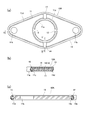
- FIG. 1 shows a joint part in the middle of a drainage channel (flow channel) 4 from a water jacket 2 formed on a cylinder block 1 in an automobile engine, through a chain case (also referred to as a front cover) 3 to a radiator (not shown).
- 5 shows an example in which the gasket 10 according to the present invention is interposed.
- the cylinder block 1 is formed with a drain port 2a of a water jacket 2, and a pipe line 41 on the cylinder block 1 side is connected to the drain port 2a.
- a flange portion 51 is formed on the front side of the pipe line 41.
- the chain case 3 has a peripheral edge portion fixed to the front side of the cylinder block 1 by bolts (not shown), whereby a chain chamber 30 is formed between the chain case 3 and the front wall (water jacket wall) 1a of the cylinder block 1. Is done.
- the chain chamber 30 is equipped with a chain and a timing belt (both not shown) for transmitting drive from the crankshaft to other auxiliary machines. In order to smoothly transmit the drive by these chains and the like, the chain chamber 30 is filled with lubricating oil (not shown).
- the chain case 3 is provided with a pipeline 42 on the chain case 3 side so as to penetrate the inside and outside of the chain case 3 at a position corresponding to the pipeline 41 on the cylinder block 1 side.
- the flange part 52 which opposes the flange part 51 by the side of the said cylinder block 1 is formed in the base part side (cylinder block 1 side) of this pipe line 42, and the said joint part 5 is comprised by both flange parts 51 and 52.
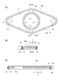
- the Both flange portions 51 and 52 have a generally rhombus shape in which the corners have arcuate corners, and the flange portion 51 on the cylinder block 1 side has corner portions on the longer diagonal line. Are formed with two bolt holes 51a, 51a, respectively.
- the flange 52 on the chain case 3 side communicates with the bolt holes 3a, 3a formed in the chain case 3 at positions corresponding to the bolt holes 51a, 51a so as to penetrate the inside and outside of the chain case 3.
- Two bolt holes 52a and 52a are formed. From the outside of the chain case 3, the bolt holes 3a, 3a of the chain case 3, the bolt holes 52a of the flange portion 52, and the bolt holes 51a of the flange portion 51 are passed through the front wall 1a of the cylinder block 1, Two drainage passage forming bolts 6 and 6 can be screwed and fastened to the two female screw portions 1b and 1b formed on the bottom side of the hole 51a.
- the gasket 10 according to the present invention is interposed between the combined surfaces of the flange portions 51, 52 while being sandwiched.
- the pipe lines 41 and 42 are connected via both flange portions 51 and 52, and the drainage path 4 leading from the drainage port 2a of the water jacket 2 to the radiator (not shown) is established.
- a stud bolt (not shown) is fixed to the front wall 1a of the cylinder block 1 and a nut (not shown) is provided from the outside of the chain case 3. May be screwed onto the stud bolt.
- the drainage side of the water jacket 2 is taken as an example, but the above configuration is also applied to the water supply side.
- the pipe case 42 including the flange portion 52 extending toward the cylinder block 1 is formed in the chain case 3 in a projecting shape.
- the drainage can be performed without using the projecting conduit 42.
- the path 4 may be formed.
- another pipe line may be connected to the drainage channel 4 on the outside of the chain case 3 in a watertight manner. .
- FIGS. 2 and 3 (a) and 3 (b). 4 to 9 show modifications of the first embodiment.
- the easily deformable portion 15 is made up of the thin portion 16 formed on the plate-like core material 11.
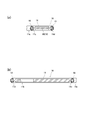
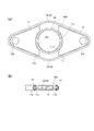
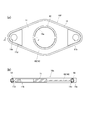
- the gasket 10 according to the first embodiment shown in FIGS. 2 and 3A and 3B includes a plate-like core material 11 having an opening 11a and an elasticity formed along the inner periphery of the opening 11a.
- An inner seal portion 12 made of a material and an outer seal portion 13 made of an elastic material formed along the outer peripheral portion of the plate-like core material 11 are provided.
- a rubber material is used as an elastic material constituting the inner seal portion 12 and the outer seal portion 13.
- the plate-like core material 11 is made of a metal plate, and the outer shape has a generally rhombus shape that substantially matches the outer shape of the flange portions 51 and 52, and the opening portion 11a has a rhombus outer shape. It is concentric with the intersection of the diagonal lines and is formed in a circular shape that substantially matches the cross-sectional shape of the drainage channel 4. Further, fastening bolt holes 11b and 11b are formed at positions corresponding to the bolt holes 51a and the bolt holes 52a of the flange portions 51 and 52 in the plate-shaped core material 11.
- the outer shape of the plate-shaped core member 11, the opening 11a, and the fastening bolt holes 11b and 11b are formed by punching.
- the said plate-shaped core material 11 is the seal
- the easily deformable portion 15 in the present embodiment includes a thin portion 16 formed so as to have the same thickness as the seal forming thin portions 11c and 11d continuously from the inner and outer seal forming thin portions 11c and 11d.
- the thin wall portion 16 is formed at two positions substantially in the middle between the fastening bolt holes 11b and 11b, that is, at positions independent of the fastening bolt holes 11b and 11b, to the seal forming thin wall portions 11c and 11d. It is formed continuously. These thin portions 11c, 11d, 15, and 15 are formed by press-molding the metal original plate of the plate-like core material 11 from both sides.
- the inner seal portion 12 and the outer seal portion 13 are formed by placing a plate-shaped core material processed into a predetermined shape in a predetermined cavity of a molding die and injecting an unvulcanized rubber material, and vulcanizing it.
- the peripheral portions of the seal-formed thin-walled portions 11c and 11d are covered and formed integrally on both the front and back surfaces.
- an elastic material which comprises the seal parts 12 and 13 soft resin can also be used besides a rubber material.
- the inner seal portion 12 and the outer seal portion 13 may be integrally formed on both the front and back surfaces without covering the respective peripheral portions of the seal forming thin portions 11c and 11d.
- the gasket 10 configured as described above is fastened to the cylinder block 1 by fastening bolts (not shown) and the two drainage passage forming bolts 6 at the peripheral edge of the chain case 3 to the cylinder block 1. It is interposed between the flange portions 51 and 52 of the joint portion 5 while being sandwiched between the flange portions 51 and 52.
- a chain chamber 30 is formed between the chain case 3 and the front wall 1a of the cylinder block 1 by attaching the chain case 3 with bolts. Lubricating oil (not shown) is provided in the chain chamber 30. Filled.
- the said drainage channel 4 is established by the connection of the joint part 5 with the gasket 10 interposed.
- a radiator (not shown).
- the inner seal portion 12 and the outer seal portion 13 are compressed in the thickness direction of the plate-like core material 11, and the reaction force causes the flange to be flanged.
- the parts 51 and 52 are in pressure contact with both opposing surfaces.
- the inner seal portion 12 in pressure contact with both opposing surfaces of the flange portions 51 and 52 prevents leakage of cooling water (not shown) flowing through the drainage channel 4 from the joint portion 5 into the chain chamber 30.
- the outer seal portion 13 in pressure contact with both opposing surfaces of the flange portions 51 and 52 prevents the oil filled in the chain chamber 30 from flowing into the drainage channel 4 from the joint portion 5.
- the joint part 5 of the pipe lines 41 and 42 exists in the chain chamber 30, it is reliably prevented that the oil in the chain chamber 30 and the cooling water flowing through the drainage channel 4 are mixed.
- Design flexibility of engine layout configuration increases.
- the plate-shaped core material 11 includes the easily deformable portion 15 by the thin-walled portion 16, even if thermal expansion or twist occurs in the flange portions 51 and 52, the plate-shaped core material 11 follows this. The deformation does not affect the sealing performance of the inner seal portion 12 and the outer seal portion 13.
- the easily deformable portion 15 is provided at a substantially middle position between the fastening bolt holes 11b and 11b, the inner and outer seal forming thin portions 11c and 11d are provided at the narrowest part, Deformation is made extremely effective.
- the easily deformable portion 15 is formed at a position independent of the fastening bolt holes 11b and 11b, the gasket 10 of the flange portions 51 and 52 is attached by fastening the drainage channel forming bolts 6 and 6.
- the fixing function is not affected by the deformation of the easily deformable portion 15, and the sealing performance is accurately maintained.
- the vicinity of the fastening bolt holes 11b and 11b is made of a rigid material so that the axial force of the drainage channel forming bolts 6 and 6 can be maintained, and the fastening bolt is interposed between the inner and outer seal portions 12 and 13. Since the holes 11b and 11b are opened, the effect by the easily deformable portion 15 can be further exhibited.
- FIGS. Is show modified examples of the gasket of the first embodiment.
- the overall shape, the inner and outer seal forming thin portions 11c and 11d, the inner and outer seal portions 12 and 13, and the thin portion 16 as the easily deformable portion 15 are the same as the gasket 10 shown in FIGS. Is formed. And it differs from the said gasket 10 in the point by which the connection part 14 which consists of an elastic material connected with the said inner seal part 12 and the outer seal part 13 is provided in both surfaces of the thin part 16 as the said easily deformable part 15.
- the joint portion 14 is made of the same rubber material as the inner seal portion 12 and the outer seal portion 13, and when vulcanized and molded as described above, unvulcanized rubber is injected from one place, and the inner seal is passed through the joint portion 14.
- the part 12 and the outer seal part 13 can be vulcanized and molded at the same time.
- the connecting portion 14 is molded to a thickness that does not protrude from the top portions of the inner seal portion 12 and the outer seal portion 13.
- the inner seal portion 12 and the outer seal portion 13 are connected to each other via the connecting portion 14, but are integrally formed with the plate-shaped core material 11 and are restrained by the plate-shaped core material 11. Independent sealing performance can be maintained without being affected by the deformation during compression.
- the easily deformable portion 15 (thin wall portion 16) can exhibit the same effect as described above together with the connecting portion 14.
- Other configurations are the same as the examples shown in FIGS. 2 and 3A and 3B, and therefore, common portions are denoted by the same reference numerals and description thereof is omitted.
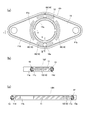
- FIGS. 5A, 5B and 5C show another modification of the gasket of the first embodiment.
- the overall shape, the inner and outer seal forming thin portions 11c and 11d, the inner seal portion 12 and the outer seal portion 13, and the thin portion 16 as the easily deformable portion 15 are the gaskets 10 and 10A of the above example. It is formed in the same way.
- the plate-shaped core material 11 differs from each said example by the point comprised in the 3 layer structure by the board
- the portion consisting only of the substrate 110 to which the side plates 111 and 111 are not fixed constitutes the seal forming thin portions 11c and 11d and the thin portion 16 as the easily deformable portion 15.
- the substrate 110 and the side plates 111, 111 are fixed by welding or caulking. Further, the substrate 110 and the side plates 111 and 111 may be the same metal plate or different metal plates. In the latter case, if a low-cost metal plate is used as the side plate 111, there is a merit of cost reduction.
- the plate-shaped core material 11 is configured by a three-layer structure of the substrate 110 and the side plates 111 and 111, the basic function is the same as in the above example, and therefore the easily deformable portion 15 (thin wall) The effect of the part 16) is exhibited in the same manner as described above.
- the connecting portions 14 similar to the example shown in FIG. 4 may be provided on both surfaces of the thin portion 16 as the easily deformable portion 15. Since other configurations are the same as those in each of the above examples, common portions are denoted by the same reference numerals and description thereof is omitted.
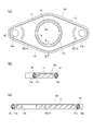
- FIG. 6A, 6B, and 6C show still another modification of the gasket of the first embodiment.
- the overall shape, the inner and outer seal forming thin portions 11c and 11d, the inner seal portion 12 and the outer seal portion 13 are formed in the same manner as in the above example, but the thin portion as the easily deformable portion 15 16 is different from the above examples. That is, four thin portions 16 are provided on both sides between the fastening bolt holes 11b and 11b, and a total of eight portions are provided so as to be continuous with the inner and outer seal forming thin portions 11c and 11d, respectively.
- the same effect as the above as the easily deformable part 15 becomes more remarkable, and the weight of the plate-shaped core material 11 can be reduced.
- the connecting portions 14 similar to the example shown in FIG. 4 may be provided on both surfaces of the thin portion 16 as the easily deformable portion 15.
- the plate-like core 11 has a three-layer structure, and only the substrate 110 constitutes the seal-formed thin portions 11 c and 11 d and the thin portion 16 as the easily deformable portion 15. May be. Since other configurations are the same as those in each of the above examples, common portions are denoted by the same reference numerals and description thereof is omitted.
- FIGS. 7A and 7B show still another modification of the gasket according to the first embodiment.
- the overall shape, the inner and outer seal forming thin portions 11c and 11d, the inner seal portion 12 and the outer seal portion 13 are formed in the same manner as in the above example.
- each of the thin portions 16 formed in two places as the easily deformable portion 15 is continuous with the seal forming thin portions 11c and 11d and is formed wider than the example shown in FIG.
- the same effect as the above-described deformable portion 15 becomes more remarkable, and the weight of the plate-like core material 11 can be further reduced. Therefore, similarly to the example shown in FIG.
- the formation mode can be selectively adopted.
- the connecting portions 14 similar to the example shown in FIG. 4 may be provided on both surfaces of the thin portion 16 as the easily deformable portion 15.
- the plate-like core 11 has a three-layer structure, and only the substrate 110 constitutes the seal-formed thin portions 11 c and 11 d and the thin portion 16 as the easily deformable portion 15. May be. Since other configurations are the same as those in each of the above examples, common portions are denoted by the same reference numerals and description thereof is omitted.
- FIGS. 8A and 8B show still another modification of the gasket of the first embodiment.
- the overall shape, the inner and outer seal forming thin portions 11c and 11d, and the inner and outer seal portions 12 and 13 are formed in the same manner as in the above example.
- the thin-walled portion 16 as the easily deformable portion 15 is continuous with the seal-formed thin-walled portions 11c, 11d, and surrounds the inner seal portion 12, and leaves a portion near the fastening bolt holes 11b, 11b. Is formed.
- the thin part 16 large, the same effect as the above as the easily deformable part 15 becomes more remarkable, and the weight of the plate-like core material 11 can be further reduced.
- the formation mode of the easy portion 15 can be selectively adopted.
- the connecting portions 14 similar to the example shown in FIG. 4 may be provided on both surfaces of the thin portion 16 as the easily deformable portion 15.
- the plate-like core 11 has a three-layer structure, and only the substrate 110 constitutes the seal-formed thin portions 11 c and 11 d and the thin portion 16 as the easily deformable portion 15. May be. Since other configurations are the same as those in each of the above examples, common portions are denoted by the same reference numerals and description thereof is omitted.
- FIGS. 9A, 9B, and 9C show still another modification of the gasket of the first embodiment.
- the overall shape, the inner and outer seal forming thin portions 11c and 11d, and the inner and outer seal portions 12 and 13 are formed in the same manner as in the above example.
- the thin-walled portion 16 as the easily deformable portion 15 is not continuous with the seal-forming thin-walled portions 11 c and 11 d but is intermittently formed at four locations around the inner seal portion 12.
- the thin portions 16 formed at these four locations are each formed in a concave groove shape that is concentric and has the same diameter as the opening 11a, and the inner seal portion 12 and the outer seal portion 13 are closest to each other.
- the part includes a wide portion 16a.
- the easily deformable portion 15 having such a formation mode also has the same effect as described above.
- the thin portion 16 includes the wide portion 16a, so that the above-described effect due to deformation is more exerted.
- the plate-like core material 11 has a three-layer structure, and only the substrate 110 constitutes the seal-formed thin portions 11 c and 11 d and the thin portion 16 as the easily deformable portion 15. You may make it do.
- the thin portion 16 is formed by punching the side plate 111. Since other configurations are the same as those in each of the above examples, common portions are denoted by the same reference numerals and description thereof is omitted.
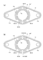
- FIGS. 10A, 10B and 10C show a second embodiment of the gasket according to the present invention, and FIGS. 11 and 12 show a modification thereof.
- the easily deformable portion 15 is made up of the through holes 17 formed in the plate-like core material 11.
- the overall shape, the inner and outer seal forming thin portions 11c and 11d, the inner seal portion 12 and the outer seal portion 13 are formed in the same manner as in each of the above examples. Yes.
- the through holes 17 as the easily deformable portions 15 are intermittently formed at six locations around the inner seal portion 12.
- the through holes 17 formed in these six places are all formed in an arc-shaped slot shape along an arc concentric with the opening 11a.
- the easily deformable portion 15 includes the slot-shaped through-holes 17, a plate-like core in the vicinity of the portion where the through-holes 17 are formed against thermal expansion and twist of the flange portions 51 and 52.
- the material 11 is easily deformed to follow, and the sealing performance of the gasket 10G is maintained. Further, the presence of the through holes 17 reduces the weight of the plate-like core material 11.
- the plate-like core material 11 can have a three-layer structure as in the example shown in FIG. In this case, after having a three-layer structure, the opening 11a, the fastening bolt holes 11b and 11b, and the through holes 17 are formed by punching.
- the other configuration is the same as that of the example shown in FIG.
- FIGS. 11A, 11B, and 11C show a modification of the gasket of the second embodiment.
- the overall shape, the inner and outer seal forming thin portions 11c and 11d, and the inner and outer seal portions 12 and 13 are formed in the same manner as in the example shown in FIG.
- the through hole 17 as the easily deformable portion 15 is a circular hole, and twelve through holes (circular holes) 17 are arranged at equal intervals around the inner seal portion 12 along a circle concentric with the opening portion 11a. It differs from the example shown in FIG. 10 in that it is formed.
- the plate-like core material 11 in the vicinity of the portion where the through hole 17 is formed easily deforms and follows the thermal expansion and torsion of the flange portions 51 and 52, and the sealing performance of the gasket 10H is maintained.
- the presence of the through-hole 17 can reduce the weight of the plate-like core material 11.
- the plate-like core material 11 can have a three-layer structure as in the example shown in FIG. In this case as well, the opening 11a, the fastening bolt holes 11b and 11b, and the through holes 17 are formed by punching after a three-layer structure.
- the other configuration is the same as that of the example shown in FIG.
- the gasket 10I of this example shows another modification of the gasket of the second embodiment.
- the overall shape, the inner and outer seal forming thin portions 11c and 11d, and the inner and outer seal portions 12 and 13 are formed in the same manner as in the example shown in FIG.
- the through hole 17 as the easily deformable portion 15 is formed in an arcuate slot shape concentric with the fastening bolt hole 11b in the vicinity of the fastening bolt hole 11b. It is different from the example shown in.
- the arc-shaped slot-shaped through-hole 17 as the easily deformable portion 15 is formed in the vicinity of the fastening bolt hole 11b, the vicinity of the through-hole 17 follows the torsion or the like generated when the bolt is fastened. It is easy to maintain the sealing performance of the gasket 10I, and the presence of the through holes 17 can reduce the weight of the plate-like core material 11.
- the slot-shaped through-hole 17 is formed in the vicinity of the fastening bolt hole 11b, propagation of deformation such as torsion during bolt fastening to other parts is effectively suppressed.
- the plate-like core material 11 can have a three-layer structure as in the example shown in FIG. In this case as well, the opening 11a, the fastening bolt holes 11b and 11b, and the through holes 17 are formed by punching after a three-layer structure. The other configuration is the same as that of the example shown in FIG.
- FIG. 13A and 13B show a modification of the example shown in FIG.
- Gasket 10F 'shown to a figure combines the gasket F shown in FIG. 9, and the gasket 10 shown in FIG.2 and FIG.3. That is, the thin portion 16 in the gasket 10 shown in FIGS. 2 and 3 is formed in a similar manner so as to partially replace the thin portion 16 at the same position in the gasket 10F shown in FIG. By such a combined structure, the effect as the easily deformable portion 15 is more remarkably exhibited.
- the gasket 10F ′′ shown in the figure is provided with the connecting parts 14 similar to the example shown in FIG. 4 on both surfaces of the thin part 16 newly replaced and formed in the figure (a).
- the above-mentioned effect by the connecting portion 14 is added to the example shown in FIG. Also in the examples shown in FIGS. 10 to 12, the easily deformable portion 15 or the connecting portion 14 in the example shown in FIGS. 2 and 3 or FIG. It is also possible to have a combination structure as shown.
- the shape of the thin portion 16 and the through hole 17 as the easily deformable portion 15 is not limited to that shown in the figure, and it may function to deform following the thermal expansion or torsion of the flange portions 51 and 52. Other forms are also possible. Further, the overall shape of the gasket, the number of fastening bolt holes 11b, the cross-sectional shapes of the inner and outer seal portions 12 and 13, and the like are not limited to the illustrated example. Furthermore, as an application example of the gasket 10 (10A to 10I) of the present invention, an example used for the joint portion 5 located in the chain case 3 as shown in FIG. 1 has been described, but a double sealing function is required. In addition, the present invention can be applied to other mechanism portions that may cause thermal expansion or twist on the mounting surface.
Abstract
La présente invention concerne un joint (10) pourvu : d'un matériau central plan (11) possédant une ouverture (11a) ; d'un élément d'étanchéité intérieur (12) comprenant un matériau élastique et formé le long de la partie périphérique intérieure de l'ouverture (11a) ; et d'un élément d'étanchéité extérieur (13) comprenant un matériau élastique et formé le long de la partie périphérique extérieure du matériau central plan (11). Le joint (10) est caractérisé en ce que le matériau central plan (11) est pourvu : de parties minces (11c, 11d) de formation d'étanchéité destinées à former l'élément d'étanchéité intérieur et l'élément d'étanchéité extérieur sur la partie périphérique intérieure et sur la partie périphérique extérieure ; et d'une partie facilitant la déformation (15) qui rend la déformation du matériau central plan (11) entre les éléments d'étanchéité intérieur et extérieur (12, 13) plus facile.
Priority Applications (3)
| Application Number | Priority Date | Filing Date | Title |
|---|---|---|---|
| EP13843332.1A EP2905515B1 (fr) | 2012-10-04 | 2013-09-30 | Joint |
| CN201380052183.5A CN104704270B (zh) | 2012-10-04 | 2013-09-30 | 密封垫 |
| US14/433,582 US10174872B2 (en) | 2012-10-04 | 2013-09-30 | Gasket |
Applications Claiming Priority (2)
| Application Number | Priority Date | Filing Date | Title |
|---|---|---|---|
| JP2012221994A JP5723846B2 (ja) | 2012-10-04 | 2012-10-04 | ガスケット |
| JP2012-221994 | 2012-10-04 |
Publications (1)
| Publication Number | Publication Date |
|---|---|
| WO2014054561A1 true WO2014054561A1 (fr) | 2014-04-10 |
Family
ID=50434888
Family Applications (1)
| Application Number | Title | Priority Date | Filing Date |
|---|---|---|---|
| PCT/JP2013/076493 WO2014054561A1 (fr) | 2012-10-04 | 2013-09-30 | Joint |
Country Status (5)
| Country | Link |
|---|---|
| US (1) | US10174872B2 (fr) |
| EP (1) | EP2905515B1 (fr) |
| JP (1) | JP5723846B2 (fr) |
| CN (1) | CN104704270B (fr) |
| WO (1) | WO2014054561A1 (fr) |
Cited By (1)
| Publication number | Priority date | Publication date | Assignee | Title |
|---|---|---|---|---|
| JP7311183B1 (ja) | 2022-02-24 | 2023-07-19 | 石川ガスケット株式会社 | シール連結体およびガスケット |
Families Citing this family (13)
| Publication number | Priority date | Publication date | Assignee | Title |
|---|---|---|---|---|
| WO2014192442A1 (fr) * | 2013-05-31 | 2014-12-04 | 協和工業株式会社 | Structure d'assemblage par brides et corps de joint d'étanchéité utilisé dans cette dernière |
| JP6276572B2 (ja) * | 2013-12-06 | 2018-02-07 | Nok株式会社 | ガスケットの成形型および製造方法 |
| CN106192295B (zh) * | 2015-05-05 | 2019-04-19 | 青岛海尔洗衣机有限公司 | 一种洗衣机内桶轴密封安装结构 |
| JP6779669B2 (ja) * | 2016-06-08 | 2020-11-04 | ナブテスコ株式会社 | シール部材及びギア装置 |
| CN106499802A (zh) * | 2016-12-19 | 2017-03-15 | 中车长春轨道客车股份有限公司 | 传感器橡胶密封垫及带有该传感器橡胶密封垫的齿轮箱 |
| CN111819378B (zh) * | 2018-03-14 | 2022-10-18 | 三菱电机株式会社 | 垫片以及制冷循环装置 |
| GB2572553A (en) * | 2018-03-29 | 2019-10-09 | Airbus Operations Ltd | Aircraft fuel tank isolator |
| CN110118133A (zh) * | 2019-06-20 | 2019-08-13 | 无锡模达科技有限公司 | 一种密封降噪的曲轴箱防尘板 |
| US10975823B2 (en) * | 2019-08-16 | 2021-04-13 | Caterpillar Inc. | Fastener-component sub-assembly |
| US11181004B2 (en) * | 2020-02-07 | 2021-11-23 | Raytheon Technologies Corporation | Confinement of a rope seal about a passage using a backing plate |
| DE202020101730U1 (de) * | 2020-03-31 | 2021-07-02 | Reinz-Dichtungs-Gmbh | Zylinderkopfdichtung |
| US11621453B2 (en) * | 2020-07-08 | 2023-04-04 | Reinz-Dichtungs-Gmbh | Foldable gasket with continuous sealing contour |
| CN116583473A (zh) * | 2020-12-10 | 2023-08-11 | 鲍勃斯脱梅克斯股份有限公司 | 用于保持平坦的柔性部件的定位装置和定位组件以及片材材料加工机 |
Citations (10)
| Publication number | Priority date | Publication date | Assignee | Title |
|---|---|---|---|---|
| JPS5476759A (en) * | 1977-11-30 | 1979-06-19 | Metex Corp | Exhaust seal |
| JPS57122856U (fr) * | 1981-01-26 | 1982-07-30 | ||
| JPS6018246U (ja) * | 1983-07-18 | 1985-02-07 | 日産ディーゼル工業株式会社 | 内燃機関のシリンダヘツドガスケツト |
| JPH10317968A (ja) | 1997-05-15 | 1998-12-02 | Suzuki Motor Corp | エンジンの冷却装置 |
| JP2000320678A (ja) * | 1999-05-12 | 2000-11-24 | Uchiyama Mfg Corp | ガスケットとその製造方法 |
| JP2004360913A (ja) * | 2003-05-30 | 2004-12-24 | Elringklinger Ag | シリンダヘッドガスケット |
| JP2005195091A (ja) * | 2004-01-07 | 2005-07-21 | Mitsubishi Cable Ind Ltd | ガスケット |
| JP2010180858A (ja) | 2009-02-09 | 2010-08-19 | Nissan Motor Co Ltd | 内燃機関のシール構造 |
| JP2010249267A (ja) | 2009-04-17 | 2010-11-04 | Tokyo Gas Co Ltd | ガスケット |
| JP2012002170A (ja) | 2010-06-18 | 2012-01-05 | Toyota Motor Corp | 内燃機関の冷却水出口構造 |
Family Cites Families (28)
| Publication number | Priority date | Publication date | Assignee | Title |
|---|---|---|---|---|
| US2191044A (en) * | 1937-11-10 | 1940-02-20 | Aluminium Plant & Vessel Co | Liquid treating apparatus of the built-up type |
| US3231289A (en) * | 1962-01-26 | 1966-01-25 | Parker Hannifin Corp | Sealing gasket |
| US3302953A (en) * | 1963-02-25 | 1967-02-07 | Clarence O Glasgow | Gasket ring and conduit coupling |
| US3578346A (en) * | 1969-01-29 | 1971-05-11 | Parker Hannifin Corp | Sealed joint and gasket therefor |
| US3738670A (en) * | 1971-09-27 | 1973-06-12 | Parker Hannifin Corp | Sectional gasket |
| US3930656A (en) * | 1974-02-22 | 1976-01-06 | Parker-Hannifin Corporation | Sealed joint and gasket therefor |
| US4294477A (en) * | 1977-06-08 | 1981-10-13 | Vetco Inc. | Flexible ring gasket retainer for flanged connectors |
| US4272085A (en) * | 1978-10-07 | 1981-06-09 | Kawasaki Jukogyo Kabushiki Kaisha | Cylinder head gasket for a liquid cooled internal combustion engine |
| FR2483522B1 (fr) * | 1980-06-02 | 1985-07-19 | Curty Soc | Joint de culasse pour moteur a combustion interne |
| US4535996A (en) * | 1985-01-18 | 1985-08-20 | Felt Products Mfg. Co. | Gasket assembly for oil pans and the like and method of making same |
| US5267740A (en) * | 1992-02-20 | 1993-12-07 | Fel-Pro Incorporated | Metal head gasket with integrated sealing aids |
| CN1072342C (zh) * | 1996-04-16 | 2001-10-03 | 诺克株式会社 | 密封垫片 |
| US5890719A (en) * | 1996-08-27 | 1999-04-06 | Parker-Hannifin Corporation | Combination metal and elastomer cylinder head gasket |
| FR2768211B1 (fr) * | 1997-09-09 | 1999-10-22 | Curty Payen Sa | Joint statique d'etancheite |
| EP1136731B1 (fr) * | 2000-03-23 | 2006-07-05 | Nichias Corporation | Joint métallique |
| US6318768B1 (en) * | 2000-05-01 | 2001-11-20 | International Truck & Engine Corp | Tubing coupler with primary and secondary sealing |
| JP2002081543A (ja) * | 2000-09-04 | 2002-03-22 | Nippon Gasket Co Ltd | 金属製ガスケット |
| DE102004045142A1 (de) * | 2003-09-17 | 2005-07-07 | Uchiyama Manufacturing Corp. | Zylinderkopfdichtung |
| US20050269788A1 (en) * | 2004-06-02 | 2005-12-08 | Grunfeld Aron A | Gasket assembly and method |
| US8186691B2 (en) | 2006-02-17 | 2012-05-29 | Parker-Hannifin Corporation | Composite seal and coupling |
| US7766391B2 (en) * | 2006-04-05 | 2010-08-03 | Doowon Climate Control Co., Ltd. | Pipe connecting structure |
| JP2008031872A (ja) * | 2006-07-26 | 2008-02-14 | Yamaha Marine Co Ltd | メタルガスケットによるシール構造 |
| CN102773354B (zh) * | 2006-08-22 | 2015-05-06 | 日本金属密封片株式会社 | 金属板的结合结构 |
| JP2010525270A (ja) * | 2007-04-24 | 2010-07-22 | ラインツーディチュングスーゲーエムベーハー | 金属製平形ガスケット |
| CN201858136U (zh) * | 2010-05-10 | 2011-06-08 | 浙江省上虞市油封制造有限公司 | 一种用于汽车转向泵的密封圈 |
| CN201827359U (zh) | 2010-08-31 | 2011-05-11 | 铁岭市友邦橡胶制品有限公司 | 一种油泵后盖组合密封垫 |
| CN202170997U (zh) | 2011-08-18 | 2012-03-21 | 昌图长汽密封制品厂 | 双唇橡胶平面密封垫片 |
| US8960682B2 (en) * | 2013-03-14 | 2015-02-24 | Federal-Mogul Corporation | Hybrid ring welded cylinder head gasket |
-
2012
- 2012-10-04 JP JP2012221994A patent/JP5723846B2/ja active Active
-
2013
- 2013-09-30 US US14/433,582 patent/US10174872B2/en active Active
- 2013-09-30 WO PCT/JP2013/076493 patent/WO2014054561A1/fr active Application Filing
- 2013-09-30 CN CN201380052183.5A patent/CN104704270B/zh active Active
- 2013-09-30 EP EP13843332.1A patent/EP2905515B1/fr active Active
Patent Citations (10)
| Publication number | Priority date | Publication date | Assignee | Title |
|---|---|---|---|---|
| JPS5476759A (en) * | 1977-11-30 | 1979-06-19 | Metex Corp | Exhaust seal |
| JPS57122856U (fr) * | 1981-01-26 | 1982-07-30 | ||
| JPS6018246U (ja) * | 1983-07-18 | 1985-02-07 | 日産ディーゼル工業株式会社 | 内燃機関のシリンダヘツドガスケツト |
| JPH10317968A (ja) | 1997-05-15 | 1998-12-02 | Suzuki Motor Corp | エンジンの冷却装置 |
| JP2000320678A (ja) * | 1999-05-12 | 2000-11-24 | Uchiyama Mfg Corp | ガスケットとその製造方法 |
| JP2004360913A (ja) * | 2003-05-30 | 2004-12-24 | Elringklinger Ag | シリンダヘッドガスケット |
| JP2005195091A (ja) * | 2004-01-07 | 2005-07-21 | Mitsubishi Cable Ind Ltd | ガスケット |
| JP2010180858A (ja) | 2009-02-09 | 2010-08-19 | Nissan Motor Co Ltd | 内燃機関のシール構造 |
| JP2010249267A (ja) | 2009-04-17 | 2010-11-04 | Tokyo Gas Co Ltd | ガスケット |
| JP2012002170A (ja) | 2010-06-18 | 2012-01-05 | Toyota Motor Corp | 内燃機関の冷却水出口構造 |
Cited By (2)
| Publication number | Priority date | Publication date | Assignee | Title |
|---|---|---|---|---|
| JP7311183B1 (ja) | 2022-02-24 | 2023-07-19 | 石川ガスケット株式会社 | シール連結体およびガスケット |
| WO2023163118A1 (fr) * | 2022-02-24 | 2023-08-31 | 石川ガスケット株式会社 | Corps de raccordement de joint et joint d'étanchéité |
Also Published As
| Publication number | Publication date |
|---|---|
| US20150260317A1 (en) | 2015-09-17 |
| EP2905515A1 (fr) | 2015-08-12 |
| JP2014074453A (ja) | 2014-04-24 |
| EP2905515B1 (fr) | 2020-08-26 |
| CN104704270B (zh) | 2017-10-03 |
| JP5723846B2 (ja) | 2015-05-27 |
| US10174872B2 (en) | 2019-01-08 |
| EP2905515A4 (fr) | 2016-06-01 |
| CN104704270A (zh) | 2015-06-10 |
Similar Documents
| Publication | Publication Date | Title |
|---|---|---|
| JP5723846B2 (ja) | ガスケット | |
| US7306235B2 (en) | Gasket assembly having isolated compression limiting device | |
| EP1740817B1 (fr) | Garniture metallique | |
| JP6501540B2 (ja) | メタルガスケット | |
| US9109707B2 (en) | Seal assembly | |
| KR20200140490A (ko) | 씰링 가스켓 | |
| US20170074401A1 (en) | Press-in-place gasket | |
| EP1574760B2 (fr) | Joint d'étanchéité | |
| US10927790B2 (en) | Cylinder head gasket | |
| JP4624491B2 (ja) | 流体機器モジュール | |
| JP2014095427A (ja) | シリンダヘッドガスケット | |
| JP2015102140A (ja) | 一体型シールワッシャ | |
| JP6890548B2 (ja) | シリンダブロックとシリンダヘッドとの密封構造 | |
| JP2006342749A (ja) | 金属ガスケット | |
| JP2005207536A (ja) | メタルガスケット | |
| JP7028665B2 (ja) | ガスケット | |
| WO2023163118A1 (fr) | Corps de raccordement de joint et joint d'étanchéité | |
| JP7426775B2 (ja) | 密封構造 | |
| JP2023119276A (ja) | 分割バンド | |
| JP6344642B2 (ja) | シリンダヘッドガスケット | |
| WO2016002709A1 (fr) | Joint de culasse | |
| JP2015025438A (ja) | 内燃機関用吸気マニホールド | |
| JP2019027396A (ja) | エンジンのシール構造 | |
| JP4400735B2 (ja) | 板金リテーナシール | |
| JP2010156441A (ja) | ガスケットの変形防止装置 |
Legal Events
| Date | Code | Title | Description |
|---|---|---|---|
| 121 | Ep: the epo has been informed by wipo that ep was designated in this application |
Ref document number: 13843332 Country of ref document: EP Kind code of ref document: A1 |
|
| DPE1 | Request for preliminary examination filed after expiration of 19th month from priority date (pct application filed from 20040101) | ||
| WWE | Wipo information: entry into national phase |
Ref document number: 14433582 Country of ref document: US |
|
| NENP | Non-entry into the national phase |
Ref country code: DE |
|
| WWE | Wipo information: entry into national phase |
Ref document number: 2013843332 Country of ref document: EP |