WO2014054561A1 - Gasket - Google Patents
Gasket Download PDFInfo
- Publication number
- WO2014054561A1 WO2014054561A1 PCT/JP2013/076493 JP2013076493W WO2014054561A1 WO 2014054561 A1 WO2014054561 A1 WO 2014054561A1 JP 2013076493 W JP2013076493 W JP 2013076493W WO 2014054561 A1 WO2014054561 A1 WO 2014054561A1
- Authority
- WO
- WIPO (PCT)
- Prior art keywords
- gasket
- seal portion
- easily deformable
- thin
- plate
- Prior art date
Links
Images


Classifications
-
- F—MECHANICAL ENGINEERING; LIGHTING; HEATING; WEAPONS; BLASTING
- F16—ENGINEERING ELEMENTS AND UNITS; GENERAL MEASURES FOR PRODUCING AND MAINTAINING EFFECTIVE FUNCTIONING OF MACHINES OR INSTALLATIONS; THERMAL INSULATION IN GENERAL
- F16L—PIPES; JOINTS OR FITTINGS FOR PIPES; SUPPORTS FOR PIPES, CABLES OR PROTECTIVE TUBING; MEANS FOR THERMAL INSULATION IN GENERAL
- F16L19/00—Joints in which sealing surfaces are pressed together by means of a member, e.g. a swivel nut, screwed on or into one of the joint parts
- F16L19/02—Pipe ends provided with collars or flanges, integral with the pipe or not, pressed together by a screwed member
- F16L19/0212—Pipe ends provided with collars or flanges, integral with the pipe or not, pressed together by a screwed member using specially adapted sealing means
- F16L19/0225—Pipe ends provided with collars or flanges, integral with the pipe or not, pressed together by a screwed member using specially adapted sealing means without sealing rings
-
- F—MECHANICAL ENGINEERING; LIGHTING; HEATING; WEAPONS; BLASTING
- F16—ENGINEERING ELEMENTS AND UNITS; GENERAL MEASURES FOR PRODUCING AND MAINTAINING EFFECTIVE FUNCTIONING OF MACHINES OR INSTALLATIONS; THERMAL INSULATION IN GENERAL
- F16J—PISTONS; CYLINDERS; SEALINGS
- F16J15/00—Sealings
- F16J15/02—Sealings between relatively-stationary surfaces
- F16J15/06—Sealings between relatively-stationary surfaces with solid packing compressed between sealing surfaces
- F16J15/10—Sealings between relatively-stationary surfaces with solid packing compressed between sealing surfaces with non-metallic packing
- F16J15/104—Sealings between relatively-stationary surfaces with solid packing compressed between sealing surfaces with non-metallic packing characterised by structure
-
- F—MECHANICAL ENGINEERING; LIGHTING; HEATING; WEAPONS; BLASTING
- F16—ENGINEERING ELEMENTS AND UNITS; GENERAL MEASURES FOR PRODUCING AND MAINTAINING EFFECTIVE FUNCTIONING OF MACHINES OR INSTALLATIONS; THERMAL INSULATION IN GENERAL
- F16J—PISTONS; CYLINDERS; SEALINGS
- F16J15/00—Sealings
- F16J15/02—Sealings between relatively-stationary surfaces
- F16J15/021—Sealings between relatively-stationary surfaces with elastic packing
- F16J15/022—Sealings between relatively-stationary surfaces with elastic packing characterised by structure or material
-
- F—MECHANICAL ENGINEERING; LIGHTING; HEATING; WEAPONS; BLASTING
- F16—ENGINEERING ELEMENTS AND UNITS; GENERAL MEASURES FOR PRODUCING AND MAINTAINING EFFECTIVE FUNCTIONING OF MACHINES OR INSTALLATIONS; THERMAL INSULATION IN GENERAL
- F16J—PISTONS; CYLINDERS; SEALINGS
- F16J15/00—Sealings
- F16J15/02—Sealings between relatively-stationary surfaces
- F16J15/06—Sealings between relatively-stationary surfaces with solid packing compressed between sealing surfaces
- F16J15/061—Sealings between relatively-stationary surfaces with solid packing compressed between sealing surfaces with positioning means
-
- F—MECHANICAL ENGINEERING; LIGHTING; HEATING; WEAPONS; BLASTING
- F16—ENGINEERING ELEMENTS AND UNITS; GENERAL MEASURES FOR PRODUCING AND MAINTAINING EFFECTIVE FUNCTIONING OF MACHINES OR INSTALLATIONS; THERMAL INSULATION IN GENERAL
- F16J—PISTONS; CYLINDERS; SEALINGS
- F16J15/00—Sealings
- F16J15/02—Sealings between relatively-stationary surfaces
- F16J15/06—Sealings between relatively-stationary surfaces with solid packing compressed between sealing surfaces
- F16J15/10—Sealings between relatively-stationary surfaces with solid packing compressed between sealing surfaces with non-metallic packing
- F16J15/102—Sealings between relatively-stationary surfaces with solid packing compressed between sealing surfaces with non-metallic packing characterised by material
-
- F—MECHANICAL ENGINEERING; LIGHTING; HEATING; WEAPONS; BLASTING
- F16—ENGINEERING ELEMENTS AND UNITS; GENERAL MEASURES FOR PRODUCING AND MAINTAINING EFFECTIVE FUNCTIONING OF MACHINES OR INSTALLATIONS; THERMAL INSULATION IN GENERAL
- F16J—PISTONS; CYLINDERS; SEALINGS
- F16J15/00—Sealings
- F16J15/02—Sealings between relatively-stationary surfaces
- F16J15/06—Sealings between relatively-stationary surfaces with solid packing compressed between sealing surfaces
- F16J15/10—Sealings between relatively-stationary surfaces with solid packing compressed between sealing surfaces with non-metallic packing
- F16J15/12—Sealings between relatively-stationary surfaces with solid packing compressed between sealing surfaces with non-metallic packing with metal reinforcement or covering
- F16J15/121—Sealings between relatively-stationary surfaces with solid packing compressed between sealing surfaces with non-metallic packing with metal reinforcement or covering with metal reinforcement
- F16J15/122—Sealings between relatively-stationary surfaces with solid packing compressed between sealing surfaces with non-metallic packing with metal reinforcement or covering with metal reinforcement generally parallel to the surfaces
-
- F—MECHANICAL ENGINEERING; LIGHTING; HEATING; WEAPONS; BLASTING
- F16—ENGINEERING ELEMENTS AND UNITS; GENERAL MEASURES FOR PRODUCING AND MAINTAINING EFFECTIVE FUNCTIONING OF MACHINES OR INSTALLATIONS; THERMAL INSULATION IN GENERAL
- F16J—PISTONS; CYLINDERS; SEALINGS
- F16J15/00—Sealings
- F16J15/02—Sealings between relatively-stationary surfaces
- F16J15/06—Sealings between relatively-stationary surfaces with solid packing compressed between sealing surfaces
- F16J15/10—Sealings between relatively-stationary surfaces with solid packing compressed between sealing surfaces with non-metallic packing
- F16J15/12—Sealings between relatively-stationary surfaces with solid packing compressed between sealing surfaces with non-metallic packing with metal reinforcement or covering
- F16J15/121—Sealings between relatively-stationary surfaces with solid packing compressed between sealing surfaces with non-metallic packing with metal reinforcement or covering with metal reinforcement
- F16J15/127—Sealings between relatively-stationary surfaces with solid packing compressed between sealing surfaces with non-metallic packing with metal reinforcement or covering with metal reinforcement the reinforcement being a compression stopper
-
- F—MECHANICAL ENGINEERING; LIGHTING; HEATING; WEAPONS; BLASTING
- F16—ENGINEERING ELEMENTS AND UNITS; GENERAL MEASURES FOR PRODUCING AND MAINTAINING EFFECTIVE FUNCTIONING OF MACHINES OR INSTALLATIONS; THERMAL INSULATION IN GENERAL
- F16L—PIPES; JOINTS OR FITTINGS FOR PIPES; SUPPORTS FOR PIPES, CABLES OR PROTECTIVE TUBING; MEANS FOR THERMAL INSULATION IN GENERAL
- F16L23/00—Flanged joints
- F16L23/16—Flanged joints characterised by the sealing means
- F16L23/18—Flanged joints characterised by the sealing means the sealing means being rings
Definitions
- the present invention relates to, for example, a cooling water flowing through a flow channel at a joint portion of the flow channel, such as when a water flow channel of a water jacket is provided through a chain chamber in an automobile engine,
- the present invention relates to a gasket that is mounted so as not to mix with oil filled in a room.
- Patent Document 1 describes that a liquid gasket is interposed at the joint.
- Patent Document 2 describes that two O-rings are disposed concentrically at the joint, the inner O-ring is used for preventing leakage of cooling water, and the outer O-ring is used for preventing oil leakage.
- Patent Document 3 describes that a plate-like seal member including an inner waterproof seal portion and an outer oil seal portion is interposed in the joint portion. In each of these examples, at the joint located in the chain chamber, the leakage of cooling water into the chain chamber and the inflow of oil into the flowing water channel are prevented.
- Patent Document 4 discloses a gasket that is not used in the above-described automobile engine, but is attached to a joint surface of a joint portion such as a gas pipe, and includes a plate-like inner peripheral gasket and a plate.
- the gasket which consists of a cylindrical outer peripheral gasket is described.
- Patent Document 1 For example, when performing maintenance (chain replacement) or the like in the chain chamber by removing the chain case, a troublesome work of removing the applied liquid gasket and reapplying the liquid gasket is necessary. It is said. Further, in Patent Document 2, two types of O-rings are prepared for fastening a chain case or during maintenance similar to the above, and it is necessary to perform an operation of mounting in predetermined ring grooves. . Furthermore, in Patent Document 3, the front end is formed by screwing a nut from the outer surface side of the chain case to a pair of stud bolts provided on a front end side wall around the cooling water outlet in the cylinder head. It is formed between a side wall part and the water flow pipe part provided in the chain case.
- the said sealing member gasket
- the base member of the seal member is a plate-like body. Therefore, when the bolts and nuts are fastened, or when the mounting part (joint part) is thermally expanded or twisted due to heat during operation of the engine, the base part cannot follow this, and the joint part There is a concern that the sealing performance deteriorates.
- the gasket shown in Patent Document 4 is composed of a plate-like inner peripheral side gasket and a plate-like outer peripheral side gasket, and is interposed in a pinched state between a pair of flanges fastened by bolts and nuts.
- the literature does not particularly mention problems due to thermal expansion or twisting of the flange portion.
- the present invention has been made in view of the above, and provides a gasket capable of maintaining the sealing performance of the inner seal portion and the outer seal portion and suppressing the influence on the sealing performance due to thermal expansion or torsion of the mounting surface.
- the purpose is to do.
- the gasket according to the present invention includes a plate-shaped core material having an opening, an inner seal portion made of an elastic material formed along the inner periphery of the opening, and an outer periphery of the plate-shaped core.
- an easily deformable portion for facilitating deformation of the plate-like core material between the inner seal portion and the outer seal portion.
- the inner peripheral portion of the opening is sealed by the inner seal portion, and leakage of the medium to be sealed flowing through the opening to the outer peripheral portion side is prevented.
- the outer peripheral portion is sealed by the outer seal portion, and the inflow of another medium to be sealed flowing outside the outer peripheral portion to the opening side is prevented.
- one gasket has a double seal structure, the structure is simple and easy to handle.
- the mounting surface for example, flange surface
- the inner seal portion and the outer seal portion that are subjected to high surface pressure while being interposed between the two members to be sealed are significantly affected by the mounting surface. Since the influence is absorbed by the deformation of the easily deformable portion provided between the seal portions and the propagation to the other seal portion is suppressed, the sealing performance can be maintained.
- the easily deformable portion may be a thin portion or a through hole. According to this, due to the presence of the thin wall portion or the through hole, deformation of the plate-like core material following the thermal expansion or torsion as described above is effectively performed, and the sealing performance in the inner seal portion and the outer seal portion is improved. The influence can be suppressed. Further, when the plate-shaped core material is composed of a metal plate, it can be easily created by sheet metal processing, including the thin wall portion or the through hole, and the weight of the plate-shaped core material can be reduced.
- the thin portion or the through hole as the easily deformable portion may be formed continuously with the inner and outer seal forming thin portions. According to this, since the thin wall portion or the through hole can be formed in a continuous state together with the seal forming thin wall portion, it is easy to process the plate-like core material. Further, since the thin wall portion or the through hole is continuous with the seal forming thin wall portion, deformation following the thermal expansion or twisting of the mounting surface of the plate-like core material is more effectively performed.
- the thin portion or the through hole may be provided with a connecting portion made of an elastic material connected to the inner seal portion and the outer seal portion.
- a connecting portion made of an elastic material connected to the inner seal portion and the outer seal portion.
- a plurality of fastening bolt holes may be provided between the inner seal portion and the outer seal portion. According to this, since the seal portion exists inside and outside, it is not necessary to provide the seal portion around the fastening bolt hole.
- the easily deformable portion may be formed at a position independent of the fastening bolt hole. According to this, the sealing performance of the gasket of the present invention is exhibited without affecting the function of fixing the member to be sealed and the gasket by fastening the bolt without being affected by the deformation of the easily deformable portion.
- the easily deformable portion may be formed between the plurality of fastening bolt holes. According to this, since the bolt is fastened, stress is easily applied to a position away from the fastening bolt hole, and by providing an easily deformable portion at this position, the mounting surface is more resistant to thermal expansion, torsion, and the like. It can respond flexibly. In particular, in a bolt fastening portion where the influence of the deformation of the mounting surface is large, it is possible to suppress the propagation of the influence to other parts, so that the sealing performance can be maintained.
- the easily deformable portion may be formed between the inner seal portion or the outer seal portion and the fastening bolt hole. Also in this case, stress is easily applied to the position away from the fastening bolt hole by fastening the bolt, so providing an easily deformable portion at this position makes the mounting surface more flexible against thermal expansion and torsion. It can correspond to. Further, it is possible to suppress the influence of the bolt fastening portion from being propagated to other parts and maintain the sealing performance.
- the easily deformable portion may be formed at a plurality of locations. According to this, even if there are a plurality of portions where thermal expansion and twisting are likely to occur, this can be handled appropriately.
- the gasket of the present invention while having a simple configuration, the respective sealing performance by the inner seal portion and the outer seal portion is appropriately maintained, and the plate-like core material includes the easily deformable portion, The influence on the sealing performance due to thermal expansion or twisting of the mounting surface can be effectively suppressed.
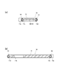
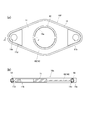
- FIG. 2A is a cross-sectional view taken along line AA in FIG. 2
- FIG. 2B is a cross-sectional view taken along line BB in FIG.
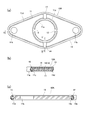
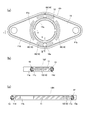
- A) is a plan view showing a modification of the gasket of the same embodiment
- (b) is a cross-sectional view taken along the line CC in FIG. (A)
- (c) is a DD line in FIG. It is arrow sectional drawing.
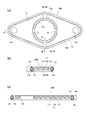
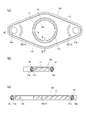
- FIG. (A) is a plan view showing another modified example of the gasket of the same embodiment, (b) is a cross-sectional view taken along line EE in FIG. (A), (c) is an F- It is F line arrow sectional drawing.
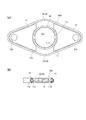
- (A) is a plan view showing still another modified example of the gasket of the same embodiment, (b) is a cross-sectional view taken along line GG in FIG. (A), (c) is H in FIG.
- FIG. (A) is a top view which shows another modification of the gasket of the same embodiment, (b) is the II sectional view taken on the line in FIG.
- FIG. 1 is a top view which shows another modification of the gasket of the same embodiment, (b) is a JJ arrow directional cross-sectional view in (a) figure.
- (A) is a plan view showing still another modified example of the gasket of the same embodiment, (b) is a cross-sectional view taken along the line KK in FIG. (A), (c) is an L in FIG.
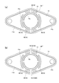
- FIG. (A) is a top view which shows 2nd Embodiment of the gasket which concerns on this invention, (b) is MM sectional view taken on the line in (a) figure, (c) is N in (a) figure FIG.
- (A) is a plan view showing a modified example of the gasket of the same embodiment, (b) is a cross-sectional view taken along line OO in (a), and (c) is a line PP in (a). It is arrow sectional drawing.
- (A) is a plan view showing another modified example of the gasket of the same embodiment, (b) is a cross-sectional view taken along the line Q-Q in FIG. (A), (c) is an R— in FIG. It is R line arrow sectional drawing.
- (A) (b) is a top view which shows the modification of the example of FIG. 9, respectively.
- FIG. 1 shows a joint part in the middle of a drainage channel (flow channel) 4 from a water jacket 2 formed on a cylinder block 1 in an automobile engine, through a chain case (also referred to as a front cover) 3 to a radiator (not shown).
- 5 shows an example in which the gasket 10 according to the present invention is interposed.
- the cylinder block 1 is formed with a drain port 2a of a water jacket 2, and a pipe line 41 on the cylinder block 1 side is connected to the drain port 2a.
- a flange portion 51 is formed on the front side of the pipe line 41.
- the chain case 3 has a peripheral edge portion fixed to the front side of the cylinder block 1 by bolts (not shown), whereby a chain chamber 30 is formed between the chain case 3 and the front wall (water jacket wall) 1a of the cylinder block 1. Is done.
- the chain chamber 30 is equipped with a chain and a timing belt (both not shown) for transmitting drive from the crankshaft to other auxiliary machines. In order to smoothly transmit the drive by these chains and the like, the chain chamber 30 is filled with lubricating oil (not shown).
- the chain case 3 is provided with a pipeline 42 on the chain case 3 side so as to penetrate the inside and outside of the chain case 3 at a position corresponding to the pipeline 41 on the cylinder block 1 side.
- the flange part 52 which opposes the flange part 51 by the side of the said cylinder block 1 is formed in the base part side (cylinder block 1 side) of this pipe line 42, and the said joint part 5 is comprised by both flange parts 51 and 52.
- the Both flange portions 51 and 52 have a generally rhombus shape in which the corners have arcuate corners, and the flange portion 51 on the cylinder block 1 side has corner portions on the longer diagonal line. Are formed with two bolt holes 51a, 51a, respectively.
- the flange 52 on the chain case 3 side communicates with the bolt holes 3a, 3a formed in the chain case 3 at positions corresponding to the bolt holes 51a, 51a so as to penetrate the inside and outside of the chain case 3.
- Two bolt holes 52a and 52a are formed. From the outside of the chain case 3, the bolt holes 3a, 3a of the chain case 3, the bolt holes 52a of the flange portion 52, and the bolt holes 51a of the flange portion 51 are passed through the front wall 1a of the cylinder block 1, Two drainage passage forming bolts 6 and 6 can be screwed and fastened to the two female screw portions 1b and 1b formed on the bottom side of the hole 51a.
- the gasket 10 according to the present invention is interposed between the combined surfaces of the flange portions 51, 52 while being sandwiched.
- the pipe lines 41 and 42 are connected via both flange portions 51 and 52, and the drainage path 4 leading from the drainage port 2a of the water jacket 2 to the radiator (not shown) is established.
- a stud bolt (not shown) is fixed to the front wall 1a of the cylinder block 1 and a nut (not shown) is provided from the outside of the chain case 3. May be screwed onto the stud bolt.
- the drainage side of the water jacket 2 is taken as an example, but the above configuration is also applied to the water supply side.
- the pipe case 42 including the flange portion 52 extending toward the cylinder block 1 is formed in the chain case 3 in a projecting shape.
- the drainage can be performed without using the projecting conduit 42.
- the path 4 may be formed.
- another pipe line may be connected to the drainage channel 4 on the outside of the chain case 3 in a watertight manner. .
- FIGS. 2 and 3 (a) and 3 (b). 4 to 9 show modifications of the first embodiment.
- the easily deformable portion 15 is made up of the thin portion 16 formed on the plate-like core material 11.
- the gasket 10 according to the first embodiment shown in FIGS. 2 and 3A and 3B includes a plate-like core material 11 having an opening 11a and an elasticity formed along the inner periphery of the opening 11a.
- An inner seal portion 12 made of a material and an outer seal portion 13 made of an elastic material formed along the outer peripheral portion of the plate-like core material 11 are provided.
- a rubber material is used as an elastic material constituting the inner seal portion 12 and the outer seal portion 13.
- the plate-like core material 11 is made of a metal plate, and the outer shape has a generally rhombus shape that substantially matches the outer shape of the flange portions 51 and 52, and the opening portion 11a has a rhombus outer shape. It is concentric with the intersection of the diagonal lines and is formed in a circular shape that substantially matches the cross-sectional shape of the drainage channel 4. Further, fastening bolt holes 11b and 11b are formed at positions corresponding to the bolt holes 51a and the bolt holes 52a of the flange portions 51 and 52 in the plate-shaped core material 11.
- the outer shape of the plate-shaped core member 11, the opening 11a, and the fastening bolt holes 11b and 11b are formed by punching.
- the said plate-shaped core material 11 is the seal
- the easily deformable portion 15 in the present embodiment includes a thin portion 16 formed so as to have the same thickness as the seal forming thin portions 11c and 11d continuously from the inner and outer seal forming thin portions 11c and 11d.
- the thin wall portion 16 is formed at two positions substantially in the middle between the fastening bolt holes 11b and 11b, that is, at positions independent of the fastening bolt holes 11b and 11b, to the seal forming thin wall portions 11c and 11d. It is formed continuously. These thin portions 11c, 11d, 15, and 15 are formed by press-molding the metal original plate of the plate-like core material 11 from both sides.
- the inner seal portion 12 and the outer seal portion 13 are formed by placing a plate-shaped core material processed into a predetermined shape in a predetermined cavity of a molding die and injecting an unvulcanized rubber material, and vulcanizing it.
- the peripheral portions of the seal-formed thin-walled portions 11c and 11d are covered and formed integrally on both the front and back surfaces.
- an elastic material which comprises the seal parts 12 and 13 soft resin can also be used besides a rubber material.
- the inner seal portion 12 and the outer seal portion 13 may be integrally formed on both the front and back surfaces without covering the respective peripheral portions of the seal forming thin portions 11c and 11d.
- the gasket 10 configured as described above is fastened to the cylinder block 1 by fastening bolts (not shown) and the two drainage passage forming bolts 6 at the peripheral edge of the chain case 3 to the cylinder block 1. It is interposed between the flange portions 51 and 52 of the joint portion 5 while being sandwiched between the flange portions 51 and 52.
- a chain chamber 30 is formed between the chain case 3 and the front wall 1a of the cylinder block 1 by attaching the chain case 3 with bolts. Lubricating oil (not shown) is provided in the chain chamber 30. Filled.
- the said drainage channel 4 is established by the connection of the joint part 5 with the gasket 10 interposed.
- a radiator (not shown).
- the inner seal portion 12 and the outer seal portion 13 are compressed in the thickness direction of the plate-like core material 11, and the reaction force causes the flange to be flanged.
- the parts 51 and 52 are in pressure contact with both opposing surfaces.
- the inner seal portion 12 in pressure contact with both opposing surfaces of the flange portions 51 and 52 prevents leakage of cooling water (not shown) flowing through the drainage channel 4 from the joint portion 5 into the chain chamber 30.
- the outer seal portion 13 in pressure contact with both opposing surfaces of the flange portions 51 and 52 prevents the oil filled in the chain chamber 30 from flowing into the drainage channel 4 from the joint portion 5.
- the joint part 5 of the pipe lines 41 and 42 exists in the chain chamber 30, it is reliably prevented that the oil in the chain chamber 30 and the cooling water flowing through the drainage channel 4 are mixed.
- Design flexibility of engine layout configuration increases.
- the plate-shaped core material 11 includes the easily deformable portion 15 by the thin-walled portion 16, even if thermal expansion or twist occurs in the flange portions 51 and 52, the plate-shaped core material 11 follows this. The deformation does not affect the sealing performance of the inner seal portion 12 and the outer seal portion 13.
- the easily deformable portion 15 is provided at a substantially middle position between the fastening bolt holes 11b and 11b, the inner and outer seal forming thin portions 11c and 11d are provided at the narrowest part, Deformation is made extremely effective.
- the easily deformable portion 15 is formed at a position independent of the fastening bolt holes 11b and 11b, the gasket 10 of the flange portions 51 and 52 is attached by fastening the drainage channel forming bolts 6 and 6.
- the fixing function is not affected by the deformation of the easily deformable portion 15, and the sealing performance is accurately maintained.
- the vicinity of the fastening bolt holes 11b and 11b is made of a rigid material so that the axial force of the drainage channel forming bolts 6 and 6 can be maintained, and the fastening bolt is interposed between the inner and outer seal portions 12 and 13. Since the holes 11b and 11b are opened, the effect by the easily deformable portion 15 can be further exhibited.
- FIGS. Is show modified examples of the gasket of the first embodiment.
- the overall shape, the inner and outer seal forming thin portions 11c and 11d, the inner and outer seal portions 12 and 13, and the thin portion 16 as the easily deformable portion 15 are the same as the gasket 10 shown in FIGS. Is formed. And it differs from the said gasket 10 in the point by which the connection part 14 which consists of an elastic material connected with the said inner seal part 12 and the outer seal part 13 is provided in both surfaces of the thin part 16 as the said easily deformable part 15.
- the joint portion 14 is made of the same rubber material as the inner seal portion 12 and the outer seal portion 13, and when vulcanized and molded as described above, unvulcanized rubber is injected from one place, and the inner seal is passed through the joint portion 14.
- the part 12 and the outer seal part 13 can be vulcanized and molded at the same time.
- the connecting portion 14 is molded to a thickness that does not protrude from the top portions of the inner seal portion 12 and the outer seal portion 13.
- the inner seal portion 12 and the outer seal portion 13 are connected to each other via the connecting portion 14, but are integrally formed with the plate-shaped core material 11 and are restrained by the plate-shaped core material 11. Independent sealing performance can be maintained without being affected by the deformation during compression.
- the easily deformable portion 15 (thin wall portion 16) can exhibit the same effect as described above together with the connecting portion 14.
- Other configurations are the same as the examples shown in FIGS. 2 and 3A and 3B, and therefore, common portions are denoted by the same reference numerals and description thereof is omitted.
- FIGS. 5A, 5B and 5C show another modification of the gasket of the first embodiment.
- the overall shape, the inner and outer seal forming thin portions 11c and 11d, the inner seal portion 12 and the outer seal portion 13, and the thin portion 16 as the easily deformable portion 15 are the gaskets 10 and 10A of the above example. It is formed in the same way.
- the plate-shaped core material 11 differs from each said example by the point comprised in the 3 layer structure by the board
- the portion consisting only of the substrate 110 to which the side plates 111 and 111 are not fixed constitutes the seal forming thin portions 11c and 11d and the thin portion 16 as the easily deformable portion 15.
- the substrate 110 and the side plates 111, 111 are fixed by welding or caulking. Further, the substrate 110 and the side plates 111 and 111 may be the same metal plate or different metal plates. In the latter case, if a low-cost metal plate is used as the side plate 111, there is a merit of cost reduction.
- the plate-shaped core material 11 is configured by a three-layer structure of the substrate 110 and the side plates 111 and 111, the basic function is the same as in the above example, and therefore the easily deformable portion 15 (thin wall) The effect of the part 16) is exhibited in the same manner as described above.
- the connecting portions 14 similar to the example shown in FIG. 4 may be provided on both surfaces of the thin portion 16 as the easily deformable portion 15. Since other configurations are the same as those in each of the above examples, common portions are denoted by the same reference numerals and description thereof is omitted.
- FIG. 6A, 6B, and 6C show still another modification of the gasket of the first embodiment.
- the overall shape, the inner and outer seal forming thin portions 11c and 11d, the inner seal portion 12 and the outer seal portion 13 are formed in the same manner as in the above example, but the thin portion as the easily deformable portion 15 16 is different from the above examples. That is, four thin portions 16 are provided on both sides between the fastening bolt holes 11b and 11b, and a total of eight portions are provided so as to be continuous with the inner and outer seal forming thin portions 11c and 11d, respectively.
- the same effect as the above as the easily deformable part 15 becomes more remarkable, and the weight of the plate-shaped core material 11 can be reduced.
- the connecting portions 14 similar to the example shown in FIG. 4 may be provided on both surfaces of the thin portion 16 as the easily deformable portion 15.
- the plate-like core 11 has a three-layer structure, and only the substrate 110 constitutes the seal-formed thin portions 11 c and 11 d and the thin portion 16 as the easily deformable portion 15. May be. Since other configurations are the same as those in each of the above examples, common portions are denoted by the same reference numerals and description thereof is omitted.
- FIGS. 7A and 7B show still another modification of the gasket according to the first embodiment.
- the overall shape, the inner and outer seal forming thin portions 11c and 11d, the inner seal portion 12 and the outer seal portion 13 are formed in the same manner as in the above example.
- each of the thin portions 16 formed in two places as the easily deformable portion 15 is continuous with the seal forming thin portions 11c and 11d and is formed wider than the example shown in FIG.
- the same effect as the above-described deformable portion 15 becomes more remarkable, and the weight of the plate-like core material 11 can be further reduced. Therefore, similarly to the example shown in FIG.
- the formation mode can be selectively adopted.
- the connecting portions 14 similar to the example shown in FIG. 4 may be provided on both surfaces of the thin portion 16 as the easily deformable portion 15.
- the plate-like core 11 has a three-layer structure, and only the substrate 110 constitutes the seal-formed thin portions 11 c and 11 d and the thin portion 16 as the easily deformable portion 15. May be. Since other configurations are the same as those in each of the above examples, common portions are denoted by the same reference numerals and description thereof is omitted.
- FIGS. 8A and 8B show still another modification of the gasket of the first embodiment.
- the overall shape, the inner and outer seal forming thin portions 11c and 11d, and the inner and outer seal portions 12 and 13 are formed in the same manner as in the above example.
- the thin-walled portion 16 as the easily deformable portion 15 is continuous with the seal-formed thin-walled portions 11c, 11d, and surrounds the inner seal portion 12, and leaves a portion near the fastening bolt holes 11b, 11b. Is formed.
- the thin part 16 large, the same effect as the above as the easily deformable part 15 becomes more remarkable, and the weight of the plate-like core material 11 can be further reduced.
- the formation mode of the easy portion 15 can be selectively adopted.
- the connecting portions 14 similar to the example shown in FIG. 4 may be provided on both surfaces of the thin portion 16 as the easily deformable portion 15.
- the plate-like core 11 has a three-layer structure, and only the substrate 110 constitutes the seal-formed thin portions 11 c and 11 d and the thin portion 16 as the easily deformable portion 15. May be. Since other configurations are the same as those in each of the above examples, common portions are denoted by the same reference numerals and description thereof is omitted.
- FIGS. 9A, 9B, and 9C show still another modification of the gasket of the first embodiment.
- the overall shape, the inner and outer seal forming thin portions 11c and 11d, and the inner and outer seal portions 12 and 13 are formed in the same manner as in the above example.
- the thin-walled portion 16 as the easily deformable portion 15 is not continuous with the seal-forming thin-walled portions 11 c and 11 d but is intermittently formed at four locations around the inner seal portion 12.
- the thin portions 16 formed at these four locations are each formed in a concave groove shape that is concentric and has the same diameter as the opening 11a, and the inner seal portion 12 and the outer seal portion 13 are closest to each other.
- the part includes a wide portion 16a.
- the easily deformable portion 15 having such a formation mode also has the same effect as described above.
- the thin portion 16 includes the wide portion 16a, so that the above-described effect due to deformation is more exerted.
- the plate-like core material 11 has a three-layer structure, and only the substrate 110 constitutes the seal-formed thin portions 11 c and 11 d and the thin portion 16 as the easily deformable portion 15. You may make it do.
- the thin portion 16 is formed by punching the side plate 111. Since other configurations are the same as those in each of the above examples, common portions are denoted by the same reference numerals and description thereof is omitted.
- FIGS. 10A, 10B and 10C show a second embodiment of the gasket according to the present invention, and FIGS. 11 and 12 show a modification thereof.
- the easily deformable portion 15 is made up of the through holes 17 formed in the plate-like core material 11.
- the overall shape, the inner and outer seal forming thin portions 11c and 11d, the inner seal portion 12 and the outer seal portion 13 are formed in the same manner as in each of the above examples. Yes.
- the through holes 17 as the easily deformable portions 15 are intermittently formed at six locations around the inner seal portion 12.
- the through holes 17 formed in these six places are all formed in an arc-shaped slot shape along an arc concentric with the opening 11a.
- the easily deformable portion 15 includes the slot-shaped through-holes 17, a plate-like core in the vicinity of the portion where the through-holes 17 are formed against thermal expansion and twist of the flange portions 51 and 52.
- the material 11 is easily deformed to follow, and the sealing performance of the gasket 10G is maintained. Further, the presence of the through holes 17 reduces the weight of the plate-like core material 11.
- the plate-like core material 11 can have a three-layer structure as in the example shown in FIG. In this case, after having a three-layer structure, the opening 11a, the fastening bolt holes 11b and 11b, and the through holes 17 are formed by punching.
- the other configuration is the same as that of the example shown in FIG.
- FIGS. 11A, 11B, and 11C show a modification of the gasket of the second embodiment.
- the overall shape, the inner and outer seal forming thin portions 11c and 11d, and the inner and outer seal portions 12 and 13 are formed in the same manner as in the example shown in FIG.
- the through hole 17 as the easily deformable portion 15 is a circular hole, and twelve through holes (circular holes) 17 are arranged at equal intervals around the inner seal portion 12 along a circle concentric with the opening portion 11a. It differs from the example shown in FIG. 10 in that it is formed.
- the plate-like core material 11 in the vicinity of the portion where the through hole 17 is formed easily deforms and follows the thermal expansion and torsion of the flange portions 51 and 52, and the sealing performance of the gasket 10H is maintained.
- the presence of the through-hole 17 can reduce the weight of the plate-like core material 11.
- the plate-like core material 11 can have a three-layer structure as in the example shown in FIG. In this case as well, the opening 11a, the fastening bolt holes 11b and 11b, and the through holes 17 are formed by punching after a three-layer structure.
- the other configuration is the same as that of the example shown in FIG.
- the gasket 10I of this example shows another modification of the gasket of the second embodiment.
- the overall shape, the inner and outer seal forming thin portions 11c and 11d, and the inner and outer seal portions 12 and 13 are formed in the same manner as in the example shown in FIG.
- the through hole 17 as the easily deformable portion 15 is formed in an arcuate slot shape concentric with the fastening bolt hole 11b in the vicinity of the fastening bolt hole 11b. It is different from the example shown in.
- the arc-shaped slot-shaped through-hole 17 as the easily deformable portion 15 is formed in the vicinity of the fastening bolt hole 11b, the vicinity of the through-hole 17 follows the torsion or the like generated when the bolt is fastened. It is easy to maintain the sealing performance of the gasket 10I, and the presence of the through holes 17 can reduce the weight of the plate-like core material 11.
- the slot-shaped through-hole 17 is formed in the vicinity of the fastening bolt hole 11b, propagation of deformation such as torsion during bolt fastening to other parts is effectively suppressed.
- the plate-like core material 11 can have a three-layer structure as in the example shown in FIG. In this case as well, the opening 11a, the fastening bolt holes 11b and 11b, and the through holes 17 are formed by punching after a three-layer structure. The other configuration is the same as that of the example shown in FIG.
- FIG. 13A and 13B show a modification of the example shown in FIG.
- Gasket 10F 'shown to a figure combines the gasket F shown in FIG. 9, and the gasket 10 shown in FIG.2 and FIG.3. That is, the thin portion 16 in the gasket 10 shown in FIGS. 2 and 3 is formed in a similar manner so as to partially replace the thin portion 16 at the same position in the gasket 10F shown in FIG. By such a combined structure, the effect as the easily deformable portion 15 is more remarkably exhibited.
- the gasket 10F ′′ shown in the figure is provided with the connecting parts 14 similar to the example shown in FIG. 4 on both surfaces of the thin part 16 newly replaced and formed in the figure (a).
- the above-mentioned effect by the connecting portion 14 is added to the example shown in FIG. Also in the examples shown in FIGS. 10 to 12, the easily deformable portion 15 or the connecting portion 14 in the example shown in FIGS. 2 and 3 or FIG. It is also possible to have a combination structure as shown.
- the shape of the thin portion 16 and the through hole 17 as the easily deformable portion 15 is not limited to that shown in the figure, and it may function to deform following the thermal expansion or torsion of the flange portions 51 and 52. Other forms are also possible. Further, the overall shape of the gasket, the number of fastening bolt holes 11b, the cross-sectional shapes of the inner and outer seal portions 12 and 13, and the like are not limited to the illustrated example. Furthermore, as an application example of the gasket 10 (10A to 10I) of the present invention, an example used for the joint portion 5 located in the chain case 3 as shown in FIG. 1 has been described, but a double sealing function is required. In addition, the present invention can be applied to other mechanism portions that may cause thermal expansion or twist on the mounting surface.
Abstract
A gasket (10) provided with: a planar core material (11) having an opening (11a); an inner seal part (12) comprising an elastic material and formed along the inner peripheral part of the opening (11a); and an outer seal part (13) comprising an elastic material and formed along the outer peripheral part of the planar core material (11). The gasket (10) is characterized by the planar core material (11) being provided with: seal-forming thin parts (11c, 11d) for forming the inner seal part and the outer seal part on the inner peripheral part and the outer peripheral part; and a deformation-easing part (15) that makes the deformation of the planar core material (11) between the inner and outer seal parts (12, 13) easier.
Description
本発明は、例えば、自動車用エンジンにおいて、ウォータジャケットの冷却水の流水路がチェーン室を貫いて設けられる場合のように、流水路の継手部に、流水路内を流通する冷却水と、チェーン室内に充填されるオイルとが混ざり合わないように装着されるガスケットに関する。
The present invention relates to, for example, a cooling water flowing through a flow channel at a joint portion of the flow channel, such as when a water flow channel of a water jacket is provided through a chain chamber in an automobile engine, The present invention relates to a gasket that is mounted so as not to mix with oil filled in a room.
自動車用エンジンにおいて、エンジンとラジエータ等とのレイアウト構造の関係で、ウォータジャケットの冷却水の流水路を、チェーン室を貫いて設けざるを得ない場合がある(例えば、特許文献1~3参照)。このようにウォータジャケットの流水路を、チェーン室を貫いて設ける場合、チェーンケースにラジエータへの流水パイプに繋がる流水管路が設けられる。そして、チェーンケースをシリンダブロック(あるいは、シリンダヘッド)にボルトの締結によって装着する際、前記ウォータジャケットの流水口に対して、前記チェーンケースの流水管路が連通するように前記締結がなされる。これによって、前記流水口から流水管路に通じる前記流水路が確立される。この流水口から流水管路との接合部は、チェーン室内に位置することになり、この接合部には、流水路からチェーン室への冷却水の漏出と、チェーン室内から流水路内へのオイルの流入を防止するために、Oリングやガスケット等のシール部材が介在される。
In an automobile engine, there is a case where a cooling water flow channel of a water jacket must be provided through the chain chamber because of the layout structure between the engine and the radiator (see, for example, Patent Documents 1 to 3). . In this way, when the water jacket flow channel is provided through the chain chamber, the chain case is provided with a flow channel connected to the flow pipe to the radiator. Then, when the chain case is attached to the cylinder block (or cylinder head) by fastening bolts, the fastening is performed so that the water pipe of the chain case communicates with the water outlet of the water jacket. As a result, the flow channel leading from the flow port to the flow channel is established. The junction from the water outlet to the water pipe is located in the chain chamber. The junction includes leakage of cooling water from the water channel to the chain chamber and oil from the chain chamber to the water channel. In order to prevent the inflow, a sealing member such as an O-ring or a gasket is interposed.
特許文献1には、前記接合部に液状ガスケットを介在させることが記載されている。また、特許文献2には、接合部に同心状に2個のOリングを介在させ、内側のOリングを冷却水の洩れ防止用、外側のOリングをオイルの洩れ防止用とすることが記載されている。さらに、特許文献3には、前記接合部に、内側の防水シール部と、外側のオイルシール部とを備えた板状のシール部材を介在させることが記載されている。これらの例では、いずれも、チェーン室内に位置する前記接合部において、冷却水のチェーン室内への漏出及びオイルの流水路内への流入の防止が図られている。
また、特許文献4には、前記のような自動車用エンジンに用いられるものではないが、ガス配管などの継手部分における接合面に装着されるガスケットであって、板状の内周側ガスケットと板状の外周側ガスケットとからなるガスケットが記載されている。Patent Document 1 describes that a liquid gasket is interposed at the joint. Patent Document 2 describes that two O-rings are disposed concentrically at the joint, the inner O-ring is used for preventing leakage of cooling water, and the outer O-ring is used for preventing oil leakage. Has been. Further, Patent Document 3 describes that a plate-like seal member including an inner waterproof seal portion and an outer oil seal portion is interposed in the joint portion. In each of these examples, at the joint located in the chain chamber, the leakage of cooling water into the chain chamber and the inflow of oil into the flowing water channel are prevented.
Patent Document 4 discloses a gasket that is not used in the above-described automobile engine, but is attached to a joint surface of a joint portion such as a gas pipe, and includes a plate-like inner peripheral gasket and a plate. The gasket which consists of a cylindrical outer peripheral gasket is described.
また、特許文献4には、前記のような自動車用エンジンに用いられるものではないが、ガス配管などの継手部分における接合面に装着されるガスケットであって、板状の内周側ガスケットと板状の外周側ガスケットとからなるガスケットが記載されている。
ところで、特許文献1においては、例えば、チェーンケースを外してチェーン室内のメンテナンス(チェーンの交換)等を行う際、塗布されている液状ガスケットを除去し、改めて液状ガスケットを塗り直すという煩わしい作業が必要とされる。また、特許文献2においては、チェーンケースを締結する際や、前記と同様のメンテナンスの際に、2種のOリングを準備しておき、所定のそれぞれのリング溝に装着する作業を必要とする。さらに、特許文献3においては、前記接合部は、シリンダヘッドにおける冷却水出口回りの前端側壁部に設けられた一対のスタッドボルトに、チェーンケースの外面側からナットを螺合することによって、前記前端側壁部と、チェーンケースに設けられた通水管部との間に形成される。そして、この接合部には前記シール部材(ガスケット)が挟圧状態で介在され、前記冷却水出口と前記通水管部とが連通して冷却水の出口通路が構成される。この場合、シール部材は、その基体部が板状体からなると解される。そのため、前記ボルト・ナットの締結の際や、エンジンの作動時における熱によって、取付部(接合部)に熱膨張やねじれが生じたりしたとき、基体部がこれに追従できず、接合部での前記シール性能が低下することが懸念される。特許文献4に示されるガスケットは、板状の内周側ガスケットと板状の外周側ガスケットとからなり、ボルト・ナットで締結される一対のフランジ間に挟圧状態で介在されるが、本特許文献においては、フランジ部の熱膨張やねじれ等による問題点について、特に言及されていない。
By the way, in Patent Document 1, for example, when performing maintenance (chain replacement) or the like in the chain chamber by removing the chain case, a troublesome work of removing the applied liquid gasket and reapplying the liquid gasket is necessary. It is said. Further, in Patent Document 2, two types of O-rings are prepared for fastening a chain case or during maintenance similar to the above, and it is necessary to perform an operation of mounting in predetermined ring grooves. . Furthermore, in Patent Document 3, the front end is formed by screwing a nut from the outer surface side of the chain case to a pair of stud bolts provided on a front end side wall around the cooling water outlet in the cylinder head. It is formed between a side wall part and the water flow pipe part provided in the chain case. And the said sealing member (gasket) is interposed in this junction part by the pinched state, and the said cooling water exit and the said water flow pipe part connect, and the cooling water exit channel | path is comprised. In this case, it is understood that the base member of the seal member is a plate-like body. Therefore, when the bolts and nuts are fastened, or when the mounting part (joint part) is thermally expanded or twisted due to heat during operation of the engine, the base part cannot follow this, and the joint part There is a concern that the sealing performance deteriorates. The gasket shown in Patent Document 4 is composed of a plate-like inner peripheral side gasket and a plate-like outer peripheral side gasket, and is interposed in a pinched state between a pair of flanges fastened by bolts and nuts. The literature does not particularly mention problems due to thermal expansion or twisting of the flange portion.
本発明は、上記に鑑みなされたもので、内シール部及び外シール部によるそれぞれのシール性能を維持するとともに、取付面の熱膨張やねじれ等によるシール性能に対する影響を抑えることができるガスケットを提供することを目的としている。
The present invention has been made in view of the above, and provides a gasket capable of maintaining the sealing performance of the inner seal portion and the outer seal portion and suppressing the influence on the sealing performance due to thermal expansion or torsion of the mounting surface. The purpose is to do.
本発明に係るガスケットは、開口部を有する板状芯材と、前記開口部の内周部に沿って形成された弾性材からなる内シール部と、前記板状芯材の外周部に沿って形成された弾性材からなる外シール部とを備えたガスケットであって、前記板状芯材は、前記内周部及び外周部に前記内シール部及び外シール部を形成するためのシール形成薄肉部と、当該内シール部及び外シール部間に前記板状芯材の変形を容易とする変形容易部とを備えたことを特徴とする。
The gasket according to the present invention includes a plate-shaped core material having an opening, an inner seal portion made of an elastic material formed along the inner periphery of the opening, and an outer periphery of the plate-shaped core. A gasket having an outer seal portion formed of an elastic material, wherein the plate-like core material is a thin seal-forming member for forming the inner seal portion and the outer seal portion on the inner peripheral portion and the outer peripheral portion. And an easily deformable portion for facilitating deformation of the plate-like core material between the inner seal portion and the outer seal portion.
これによれば、内シール部によって前記開口部の内周部がシールされ、開口部を流通するシール対象媒体の外周部側への漏出が防止される。また、外シール部によって外周部がシールされ、外周部の外方を流通する別のシール対象媒体の前記開口部側へ流入が防止される。このように1個のガスケットで2重のシール構造を有しているにも関わらず、その構造が簡易で取扱いも容易である。また、板状芯材に変形容易部が存在していることにより、取付状態で取付面(例えば、フランジ面)に熱膨張やねじれ等あった場合、これに追従して変形し、これを吸収するから、柔軟に対応でき、シール性能が低下することなく維持される。そして、シール対象の2部材間に介装された状態で高い面圧がかかる前記内シール部及び外シール部においては、前記取付面の影響を顕著に受けることになるが、内シール部及び外シール部間に設けた変形容易部の変形によりその影響が吸収され、他方のシール部へ伝播されることが抑えられるので、シール性能が維持できる。
According to this, the inner peripheral portion of the opening is sealed by the inner seal portion, and leakage of the medium to be sealed flowing through the opening to the outer peripheral portion side is prevented. Further, the outer peripheral portion is sealed by the outer seal portion, and the inflow of another medium to be sealed flowing outside the outer peripheral portion to the opening side is prevented. Although one gasket has a double seal structure, the structure is simple and easy to handle. In addition, since there is an easily deformable part in the plate-shaped core material, if there is thermal expansion or twisting on the mounting surface (for example, flange surface) in the mounted state, it deforms following this and absorbs this. Therefore, it can respond flexibly and can maintain the sealing performance without deteriorating. The inner seal portion and the outer seal portion that are subjected to high surface pressure while being interposed between the two members to be sealed are significantly affected by the mounting surface. Since the influence is absorbed by the deformation of the easily deformable portion provided between the seal portions and the propagation to the other seal portion is suppressed, the sealing performance can be maintained.
本発明のガスケットにおいて、前記変形容易部は、薄肉部又は透孔からなるものであっても良い。これによれば、薄肉部又は透孔の存在によって、前記のような熱膨張やねじれ等に追従した板状芯材の変形が効果的になされ、内シール部及び外シール部におけるシール性能への影響を抑制することができる。また、板状芯材を金属板で構成する場合、板金加工によって、薄肉部又は透孔も含めて簡易に作成することができ、板状芯材の重量を軽減させることができる。
In the gasket of the present invention, the easily deformable portion may be a thin portion or a through hole. According to this, due to the presence of the thin wall portion or the through hole, deformation of the plate-like core material following the thermal expansion or torsion as described above is effectively performed, and the sealing performance in the inner seal portion and the outer seal portion is improved. The influence can be suppressed. Further, when the plate-shaped core material is composed of a metal plate, it can be easily created by sheet metal processing, including the thin wall portion or the through hole, and the weight of the plate-shaped core material can be reduced.
本発明のガスケットにおいて、前記変形容易部としての薄肉部又は透孔は、前記内外のシール形成薄肉部に連続して形成されているものであっても良い。これによれば、薄肉部又は透孔は、シール形成薄肉部とともに連続した状態で形成できるから、板状芯材の加工がし易い。また、薄肉部又は透孔がシール形成薄肉部に連続していることにより、板状芯材の前記取付面の熱膨張やねじれ等に追従した変形がより効果的になされる。
In the gasket of the present invention, the thin portion or the through hole as the easily deformable portion may be formed continuously with the inner and outer seal forming thin portions. According to this, since the thin wall portion or the through hole can be formed in a continuous state together with the seal forming thin wall portion, it is easy to process the plate-like core material. Further, since the thin wall portion or the through hole is continuous with the seal forming thin wall portion, deformation following the thermal expansion or twisting of the mounting surface of the plate-like core material is more effectively performed.
本発明のガスケットにおいて、前記薄肉部又は透孔には、前記内シール部及び外シール部に繋がる弾性材からなる繋ぎ部が設けられているようにしても良い。これによれば、内シール部及び外シール部を、例えば、ゴム材の成型体からなるものとすれば、所定の形状に加工した板状芯材を成型型の所定のキャビティ内に配置してゴム材を注入成型する際に、1箇所の注入口であっても、繋ぎ部を通じて内シール部及び外シール部を同時に成型することができる。
In the gasket of the present invention, the thin portion or the through hole may be provided with a connecting portion made of an elastic material connected to the inner seal portion and the outer seal portion. According to this, if the inner seal portion and the outer seal portion are made of, for example, a molded body of rubber material, a plate-shaped core material processed into a predetermined shape is disposed in a predetermined cavity of the molding die. When injecting and molding the rubber material, the inner seal portion and the outer seal portion can be simultaneously formed through the connecting portion even at one injection port.
本発明のガスケットにおいて、前記内シール部及び外シール部間に、複数の締結用ボルト孔が開設されているものとしても良い。これによれば、内外にシール部が存在するから、締結用ボルト孔の回りにシール部を設ける必要がない。
In the gasket of the present invention, a plurality of fastening bolt holes may be provided between the inner seal portion and the outer seal portion. According to this, since the seal portion exists inside and outside, it is not necessary to provide the seal portion around the fastening bolt hole.
本発明のガスケットにおいて、前記変形容易部が、前記締結用ボルト孔とは独立した位置に形成されているようにしても良い。これによれば、ボルトの締結により、シール対象部材とガスケットとを固定させる機能に、変形容易部の変形による影響が及ぶことなく、本発明のガスケットの前記シール性能が発揮される。
In the gasket of the present invention, the easily deformable portion may be formed at a position independent of the fastening bolt hole. According to this, the sealing performance of the gasket of the present invention is exhibited without affecting the function of fixing the member to be sealed and the gasket by fastening the bolt without being affected by the deformation of the easily deformable portion.
本発明のガスケットにおいて、前記変形容易部が、前記複数の締結用ボルト孔間に形成されているものとしても良い。これによれば、ボルトの締結により、締結用ボルト孔から離れた位置にストレスがかかり易いので、この位置に変形容易部を設けることにより、前記取付面の熱膨張やねじれ等に対して、より柔軟に対応できる。特に、前記取付面の変形の影響が大きいボルト締結部では、その影響を他の部位へ伝播することが抑えられるので、シール性能が維持できる。
In the gasket of the present invention, the easily deformable portion may be formed between the plurality of fastening bolt holes. According to this, since the bolt is fastened, stress is easily applied to a position away from the fastening bolt hole, and by providing an easily deformable portion at this position, the mounting surface is more resistant to thermal expansion, torsion, and the like. It can respond flexibly. In particular, in a bolt fastening portion where the influence of the deformation of the mounting surface is large, it is possible to suppress the propagation of the influence to other parts, so that the sealing performance can be maintained.
本発明のガスケットにおいて、前記変形容易部が、前記内シール部又は外シール部と前記締結用ボルト孔との間に形成されているものとしても良い。この場合も、ボルトの締結により、締結用ボルト孔から離れた位置にストレスがかかり易いので、この位置に変形容易部を設けることにより、前記取付面の熱膨張やねじれ等に対して、より柔軟に対応できる。また、前記ボルト締結部の影響を他の部位へ伝播することが抑えられ、シール性能が維持できる。
In the gasket of the present invention, the easily deformable portion may be formed between the inner seal portion or the outer seal portion and the fastening bolt hole. Also in this case, stress is easily applied to the position away from the fastening bolt hole by fastening the bolt, so providing an easily deformable portion at this position makes the mounting surface more flexible against thermal expansion and torsion. It can correspond to. Further, it is possible to suppress the influence of the bolt fastening portion from being propagated to other parts and maintain the sealing performance.
本発明のガスケットにおいて、前記変形容易部が、複数個所に形成されているものとしても良い。これによれば、熱膨張やねじれ現象が生じ易い部位が複数個所であっても、これに適正に対応できる。
In the gasket of the present invention, the easily deformable portion may be formed at a plurality of locations. According to this, even if there are a plurality of portions where thermal expansion and twisting are likely to occur, this can be handled appropriately.
本発明のガスケットによれば、簡易な構成でありながら、内シール部及び外シール部によるそれぞれのシール性能が適正に維持されるとともに、板状芯材が変形容易部を備えていることにより、取付面の熱膨張やねじれ等によるシール性能に対する影響を効果的に抑えることができる。
According to the gasket of the present invention, while having a simple configuration, the respective sealing performance by the inner seal portion and the outer seal portion is appropriately maintained, and the plate-like core material includes the easily deformable portion, The influence on the sealing performance due to thermal expansion or twisting of the mounting surface can be effectively suppressed.
以下に本発明の実施の形態について、図面を参照して説明する。先ず、図1を参照して、本発明に係るガスケットの適用例について説明する。図1は、自動車用エンジンにおけるシリンダブロック1に形成されるウォータジャケット2から、チェーンケース(フロントカバーとも言う)3を貫きラジエータ(不図示)に至る排水路(流水路)4の途中の継手部5に、本発明に係るガスケット10を介在させた例を示している。シリンダブロック1には、ウォータジャケット2の排水口2aが形成され、該排水口2aにシリンダブロック1側の管路41が連設されている。該管路41の先側にはフランジ部51が形成されている。前記チェーンケース3は、その周縁部分がシリンダブロック1のフロント側に、不図示のボルトによって固定され、これによって、シリンダブロック1のフロント壁(ウォータジャケット壁)1aとの間にチェーン室30が形成される。このチェーン室30には、クランク軸から他の補機等へ駆動伝達するためのチェーンやタイミングベルト(いずれも不図示)が装備される。そして、これらチェーン等による駆動伝達を円滑に行うために、チェーン室30内に潤滑用オイル(不図示)が充填される。
Hereinafter, embodiments of the present invention will be described with reference to the drawings. First, an application example of the gasket according to the present invention will be described with reference to FIG. FIG. 1 shows a joint part in the middle of a drainage channel (flow channel) 4 from a water jacket 2 formed on a cylinder block 1 in an automobile engine, through a chain case (also referred to as a front cover) 3 to a radiator (not shown). 5 shows an example in which the gasket 10 according to the present invention is interposed. The cylinder block 1 is formed with a drain port 2a of a water jacket 2, and a pipe line 41 on the cylinder block 1 side is connected to the drain port 2a. A flange portion 51 is formed on the front side of the pipe line 41. The chain case 3 has a peripheral edge portion fixed to the front side of the cylinder block 1 by bolts (not shown), whereby a chain chamber 30 is formed between the chain case 3 and the front wall (water jacket wall) 1a of the cylinder block 1. Is done. The chain chamber 30 is equipped with a chain and a timing belt (both not shown) for transmitting drive from the crankshaft to other auxiliary machines. In order to smoothly transmit the drive by these chains and the like, the chain chamber 30 is filled with lubricating oil (not shown).
前記チェーンケース3には、前記シリンダブロック1側の管路41に対応する位置にチェーンケース3側の管路42がチェーンケース3の内外を貫くように設けられている。そして、この管路42の基部側(シリンダブロック1側)には前記シリンダブロック1側のフランジ部51に対向するフランジ部52が形成され、両フランジ部51,52によって前記継手部5が構成される。両フランジ部51,52は、その対向面の形状が、角部が円弧形状とされた概ねひし形の形状をなし、シリンダブロック1側のフランジ部51には、その長い方の対角線上の角部の近傍にそれぞれ2個のボルト穴51a,51aが形成されている。また、チェーンケース3側のフランジ部52には、前記ボルト穴51a,51aに対応する位置に、チェーンケース3に形成されるボルト孔3a,3aと連通してチェーンケース3の内外を貫くように2個のボルト孔52a,52aが形成されている。チェーンケース3の外側より、該チェーンケース3のボルト孔3a,3a、前記フランジ部52のボルト孔52a及び前記フランジ部51のボルト穴51aを通し、シリンダブロック1のフロント壁1aであって、ボルト穴51aの底部側に形成された2個の雌ねじ部1b,1bに、2本の排水路形成用ボルト6,6を螺合して締結し得るようになされている。この2本のボルト6,6を締結するに際して、前記両フランジ部51,52の合体面間に、本発明に係るガスケット10が挟圧された状態で介在される。これによって、両フランジ部51,52を介して前記管路41,42が連結されて、ウォータジャケット2の排水口2aから、不図示のラジエータに通じる排水路4が確立される。
なお、図例のような排水路形成用ボルト6,6による締結に代え、シリンダブロック1のフロント壁1aにスタッドボルト(不図示)を固設し、チェーンケース3の外側からナット(不図示)をこのスタッドボルトに螺合させるようにしても良い。また、図例ではウォータジャケット2の排水側を例に採ったが、給水側にも前記のような構成が適用される。さらに、図例ではチェーンケース3に、シリンダブロック1側に延びるフランジ部52を含む管路42を突状に形成した例を示したが、このような突状の管路42を介さずに排水路4を形成しても良い。加えて、チェーンケース3の外側に、排水路4が一体に連なる例を示しているが、チェーンケース3の外側に別の管路を該排水路4に水密的に連結するようにしても良い。 Thechain case 3 is provided with a pipeline 42 on the chain case 3 side so as to penetrate the inside and outside of the chain case 3 at a position corresponding to the pipeline 41 on the cylinder block 1 side. And the flange part 52 which opposes the flange part 51 by the side of the said cylinder block 1 is formed in the base part side (cylinder block 1 side) of this pipe line 42, and the said joint part 5 is comprised by both flange parts 51 and 52. As shown in FIG. The Both flange portions 51 and 52 have a generally rhombus shape in which the corners have arcuate corners, and the flange portion 51 on the cylinder block 1 side has corner portions on the longer diagonal line. Are formed with two bolt holes 51a, 51a, respectively. Further, the flange 52 on the chain case 3 side communicates with the bolt holes 3a, 3a formed in the chain case 3 at positions corresponding to the bolt holes 51a, 51a so as to penetrate the inside and outside of the chain case 3. Two bolt holes 52a and 52a are formed. From the outside of the chain case 3, the bolt holes 3a, 3a of the chain case 3, the bolt holes 52a of the flange portion 52, and the bolt holes 51a of the flange portion 51 are passed through the front wall 1a of the cylinder block 1, Two drainage passage forming bolts 6 and 6 can be screwed and fastened to the two female screw portions 1b and 1b formed on the bottom side of the hole 51a. When fastening the two bolts 6, 6, the gasket 10 according to the present invention is interposed between the combined surfaces of the flange portions 51, 52 while being sandwiched. As a result, the pipe lines 41 and 42 are connected via both flange portions 51 and 52, and the drainage path 4 leading from the drainage port 2a of the water jacket 2 to the radiator (not shown) is established.
In place of fastening with drainage channel forming bolts 6 and 6 as shown in the figure, a stud bolt (not shown) is fixed to the front wall 1a of the cylinder block 1 and a nut (not shown) is provided from the outside of the chain case 3. May be screwed onto the stud bolt. In the illustrated example, the drainage side of the water jacket 2 is taken as an example, but the above configuration is also applied to the water supply side. Further, in the illustrated example, the pipe case 42 including the flange portion 52 extending toward the cylinder block 1 is formed in the chain case 3 in a projecting shape. However, the drainage can be performed without using the projecting conduit 42. The path 4 may be formed. In addition, although an example in which the drainage channel 4 is integrally connected to the outside of the chain case 3 is shown, another pipe line may be connected to the drainage channel 4 on the outside of the chain case 3 in a watertight manner. .
なお、図例のような排水路形成用ボルト6,6による締結に代え、シリンダブロック1のフロント壁1aにスタッドボルト(不図示)を固設し、チェーンケース3の外側からナット(不図示)をこのスタッドボルトに螺合させるようにしても良い。また、図例ではウォータジャケット2の排水側を例に採ったが、給水側にも前記のような構成が適用される。さらに、図例ではチェーンケース3に、シリンダブロック1側に延びるフランジ部52を含む管路42を突状に形成した例を示したが、このような突状の管路42を介さずに排水路4を形成しても良い。加えて、チェーンケース3の外側に、排水路4が一体に連なる例を示しているが、チェーンケース3の外側に別の管路を該排水路4に水密的に連結するようにしても良い。 The
In place of fastening with drainage
前記継手部5に介在されるガスケットの第1の実施形態を、図2及び図3(a)(b)をも参照して説明する。図4~図9は、この第1の実施形態の変形例を示す。これらの実施形態では、変形容易部15が、板状芯材11に形成された薄肉部16からなることで共通している。
図2及び図3(a)(b)に示す第1の実施形態のガスケット10は、開口部11aを有する板状芯材11と、前記開口部11aの内周部に沿って形成された弾性材からなる内シール部12と、前記板状芯材11の外周部に沿って形成された弾性材からなる外シール部13とを備えている。この実施形態では、内シール部12及び外シール部13を構成する弾性材としてゴム材が用いられている。板状芯材11は、金属板からなり、外形状は前記フランジ部51,52の外形状にほぼ整合する概ねひし形状の形状をなし、また、前記開口部11aは、ひし形状の外形状の対角線の交点と同心で、かつ、前記排水路4の断面形状にほぼ整合するような円形状に形成されている。さらに、当該板状芯材11における、前記フランジ部51,52のボルト穴51a及びボルト孔52aに対応する位置には、締結用ボルト孔11b,11bが開設されている。前記板状芯材11における外形状、前記開口部11a,及び締結用ボルト孔11b,11bは、打抜き加工によって形成される。 A first embodiment of the gasket interposed in thejoint portion 5 will be described with reference to FIGS. 2 and 3 (a) and 3 (b). 4 to 9 show modifications of the first embodiment. In these embodiments, the easily deformable portion 15 is made up of the thin portion 16 formed on the plate-like core material 11.
Thegasket 10 according to the first embodiment shown in FIGS. 2 and 3A and 3B includes a plate-like core material 11 having an opening 11a and an elasticity formed along the inner periphery of the opening 11a. An inner seal portion 12 made of a material and an outer seal portion 13 made of an elastic material formed along the outer peripheral portion of the plate-like core material 11 are provided. In this embodiment, a rubber material is used as an elastic material constituting the inner seal portion 12 and the outer seal portion 13. The plate-like core material 11 is made of a metal plate, and the outer shape has a generally rhombus shape that substantially matches the outer shape of the flange portions 51 and 52, and the opening portion 11a has a rhombus outer shape. It is concentric with the intersection of the diagonal lines and is formed in a circular shape that substantially matches the cross-sectional shape of the drainage channel 4. Further, fastening bolt holes 11b and 11b are formed at positions corresponding to the bolt holes 51a and the bolt holes 52a of the flange portions 51 and 52 in the plate-shaped core material 11. The outer shape of the plate-shaped core member 11, the opening 11a, and the fastening bolt holes 11b and 11b are formed by punching.
図2及び図3(a)(b)に示す第1の実施形態のガスケット10は、開口部11aを有する板状芯材11と、前記開口部11aの内周部に沿って形成された弾性材からなる内シール部12と、前記板状芯材11の外周部に沿って形成された弾性材からなる外シール部13とを備えている。この実施形態では、内シール部12及び外シール部13を構成する弾性材としてゴム材が用いられている。板状芯材11は、金属板からなり、外形状は前記フランジ部51,52の外形状にほぼ整合する概ねひし形状の形状をなし、また、前記開口部11aは、ひし形状の外形状の対角線の交点と同心で、かつ、前記排水路4の断面形状にほぼ整合するような円形状に形成されている。さらに、当該板状芯材11における、前記フランジ部51,52のボルト穴51a及びボルト孔52aに対応する位置には、締結用ボルト孔11b,11bが開設されている。前記板状芯材11における外形状、前記開口部11a,及び締結用ボルト孔11b,11bは、打抜き加工によって形成される。 A first embodiment of the gasket interposed in the
The
そして、前記板状芯材11は、前記内周部及び外周部に前記内シール部12及び外シール部13を形成するためのシール形成薄肉部11c,11dと、当該内外シール部12,13間に前記芯材11の変形を容易化する変形容易部15とを備えている。本実施形態における変形容易部15は、前記内外のシール形成薄肉部11c,11dに連続して、該シール形成薄肉部11c,11dと同厚みとなるよう形成された薄肉部16からなる。さらに、この薄肉部16は、前記締結用ボルト孔11b,11b間のほぼ中間位置の2箇所、即ち、当該締結用ボルト孔11b,11bとは独立した位置に前記シール形成薄肉部11c,11dに連続して形成されている。これら薄肉部11c,11d,15,15は、前記板状芯材11の金属原板を両面からプレス成形することにより形成される。また、前記内シール部12及び外シール部13は、所定の形状に加工した板状芯材を成型型の所定のキャビティ内に配置して未加硫のゴム材を注入し、これを加硫成型することにより、前記シール形成薄肉部11c,11dに、その周縁部を覆い表裏両面に一体に形成される。
なお、シール部12,13を構成する弾性材としては、ゴム材以外に軟質樹脂も用いることができる。また、前記内シール部12及び外シール部13は、前記シール形成薄肉部11c,11dのそれぞれの周縁部を覆わず、表裏両面に個別に一体に形成されたものであっても良い。 And the said plate-shapedcore material 11 is the seal | sticker formation thin part 11c and 11d for forming the said inner seal part 12 and the outer seal part 13 in the said inner peripheral part and outer peripheral part, and the said inner and outer seal parts 12 and 13 between And an easily deformable portion 15 for facilitating the deformation of the core material 11. The easily deformable portion 15 in the present embodiment includes a thin portion 16 formed so as to have the same thickness as the seal forming thin portions 11c and 11d continuously from the inner and outer seal forming thin portions 11c and 11d. Further, the thin wall portion 16 is formed at two positions substantially in the middle between the fastening bolt holes 11b and 11b, that is, at positions independent of the fastening bolt holes 11b and 11b, to the seal forming thin wall portions 11c and 11d. It is formed continuously. These thin portions 11c, 11d, 15, and 15 are formed by press-molding the metal original plate of the plate-like core material 11 from both sides. The inner seal portion 12 and the outer seal portion 13 are formed by placing a plate-shaped core material processed into a predetermined shape in a predetermined cavity of a molding die and injecting an unvulcanized rubber material, and vulcanizing it. By molding, the peripheral portions of the seal-formed thin- walled portions 11c and 11d are covered and formed integrally on both the front and back surfaces.
In addition, as an elastic material which comprises the seal parts 12 and 13, soft resin can also be used besides a rubber material. Further, the inner seal portion 12 and the outer seal portion 13 may be integrally formed on both the front and back surfaces without covering the respective peripheral portions of the seal forming thin portions 11c and 11d.
なお、シール部12,13を構成する弾性材としては、ゴム材以外に軟質樹脂も用いることができる。また、前記内シール部12及び外シール部13は、前記シール形成薄肉部11c,11dのそれぞれの周縁部を覆わず、表裏両面に個別に一体に形成されたものであっても良い。 And the said plate-shaped
In addition, as an elastic material which comprises the
前記のように構成されるガスケット10は、図1に示すように、チェーンケース3の周縁部における不図示のボルト及び前記2本の排水路形成用ボルト6をシリンダブロック1に締結することによって、継手部5のフランジ部51,52間に挟圧された状態で介在される。前記のとおり、チェーンケース3のボルトによる取付けによって、該チェーンケース3とシリンダブロック1のフロント壁1aとの間にチェーン室30が形成され、このチェーン室30には潤滑用オイル(不図示)が充填される。また、ガスケット10を介在させた継手部5の連結によって、前記排水路4が確立される。該排水路4には前記ウォータジャケット2からの冷却水が、不図示のラジエータに向け流通する。ガスケット10がフランジ部51,52間に挟圧された状態で介在することによって、前記内シール部12及び外シール部13は、板状芯材11の厚み方向に圧縮され、その反力によってフランジ部51,52の両対向面に圧接した状態とされる。フランジ部51,52の両対向面に圧接した状態の内シール部12によって、前記排水路4を流通する冷却水(不図示)の、継手部5からチェーン室30内への漏出が防止される。また、フランジ部51,52の両対向面に圧接した状態の外シール部13によって、チェーン室30に充填されるオイルの、継手部5から排水路4への流入が防止される。
As shown in FIG. 1, the gasket 10 configured as described above is fastened to the cylinder block 1 by fastening bolts (not shown) and the two drainage passage forming bolts 6 at the peripheral edge of the chain case 3 to the cylinder block 1. It is interposed between the flange portions 51 and 52 of the joint portion 5 while being sandwiched between the flange portions 51 and 52. As described above, a chain chamber 30 is formed between the chain case 3 and the front wall 1a of the cylinder block 1 by attaching the chain case 3 with bolts. Lubricating oil (not shown) is provided in the chain chamber 30. Filled. Moreover, the said drainage channel 4 is established by the connection of the joint part 5 with the gasket 10 interposed. Cooling water from the water jacket 2 flows through the drainage channel 4 toward a radiator (not shown). By interposing the gasket 10 in a state of being sandwiched between the flange portions 51 and 52, the inner seal portion 12 and the outer seal portion 13 are compressed in the thickness direction of the plate-like core material 11, and the reaction force causes the flange to be flanged. The parts 51 and 52 are in pressure contact with both opposing surfaces. The inner seal portion 12 in pressure contact with both opposing surfaces of the flange portions 51 and 52 prevents leakage of cooling water (not shown) flowing through the drainage channel 4 from the joint portion 5 into the chain chamber 30. . Further, the outer seal portion 13 in pressure contact with both opposing surfaces of the flange portions 51 and 52 prevents the oil filled in the chain chamber 30 from flowing into the drainage channel 4 from the joint portion 5.
したがって、チェーン室30内には管路41,42の継手部5が存在するが、チェーン室30内のオイルと排水路4を流通する冷却水とが混ざり合うことが確実に防止され、これによって、エンジンのレイアウト構成の設計自由度が増える。また、板状芯材11は、薄肉部16による変形容易部15を備えているから、フランジ部51,52に熱膨張やねじれ等が生じても、板状芯材11がこれに追従して変形し、前記内シール部12及び外シール部13によるシール性能に影響を生じることがない。しかも、変形容易部15は、前記締結用ボルト孔11b,11bのほぼ中間位置に設けられているから、内外のシール形成薄肉部11c、11dの間隔が最も狭い部位に設けられることになり、前記変形が極めて効果的になされる。また、変形容易部15が、前記締結用ボルト孔11b,11bとは独立した位置に形成されているから、前記排水路形成用ボルト6,6の締結により、フランジ部51,52のガスケット10を介した固定機能に、当該変形容易部15の変形による影響が及ばず、シール性能が的確に維持される。さらに、締結用ボルト孔11b,11bの近傍部は、前記排水路形成用ボルト6,6の軸力を保持できるように剛性のある材料で構成され、内外シール部12,13間に締結用ボルト孔11b,11bが開設されていることから、変形容易部15による前記効果がより発揮できる。
Therefore, although the joint part 5 of the pipe lines 41 and 42 exists in the chain chamber 30, it is reliably prevented that the oil in the chain chamber 30 and the cooling water flowing through the drainage channel 4 are mixed. , Design flexibility of engine layout configuration increases. Further, since the plate-shaped core material 11 includes the easily deformable portion 15 by the thin-walled portion 16, even if thermal expansion or twist occurs in the flange portions 51 and 52, the plate-shaped core material 11 follows this. The deformation does not affect the sealing performance of the inner seal portion 12 and the outer seal portion 13. In addition, since the easily deformable portion 15 is provided at a substantially middle position between the fastening bolt holes 11b and 11b, the inner and outer seal forming thin portions 11c and 11d are provided at the narrowest part, Deformation is made extremely effective. Further, since the easily deformable portion 15 is formed at a position independent of the fastening bolt holes 11b and 11b, the gasket 10 of the flange portions 51 and 52 is attached by fastening the drainage channel forming bolts 6 and 6. The fixing function is not affected by the deformation of the easily deformable portion 15, and the sealing performance is accurately maintained. Further, the vicinity of the fastening bolt holes 11b and 11b is made of a rigid material so that the axial force of the drainage channel forming bolts 6 and 6 can be maintained, and the fastening bolt is interposed between the inner and outer seal portions 12 and 13. Since the holes 11b and 11b are opened, the effect by the easily deformable portion 15 can be further exhibited.
図4(a)(b)(c)は、前記第1の実施形態のガスケットの変形例を示している。この例のガスケット10Aにおいても、全体形状、内外のシール形成薄肉部11c,11d、内外シール部12,13及び変形容易部15としての薄肉部16が、図2及び図3に示すガスケット10と同様に形成されている。そして、前記変形容易部15としての薄肉部16の両面に、前記内シール部12及び外シール部13に繋がる弾性材からなる繋ぎ部14が設けられている点で、前記ガスケット10と異なる。この繋ぎ部14は、前記内シール部12及び外シール部13と同じゴム材からなり、前記のように加硫成型する際、1箇所から未加硫ゴムを注入し、繋ぎ部14を通じて内シール部12及び外シール部13を同時に加硫成型することができる。この場合、繋ぎ部14は、前記内シール部12及び外シール部13のそれぞれの頂部より突出しない厚みに成型される。このように、内シール部12及び外シール部13は、繋ぎ部14を介して相互に繋がっているが、板状芯材11に一体に形成されて板状芯材11に拘束されているので、前記圧縮時におけるそれぞれの変形の影響を受けず、独立したシール性能を維持することができる。また、前記変形容易部15(薄肉部16)は、繋ぎ部14と共に前記と同様の効果を発揮することができる。
その他の構成は、図2及び図3(a)(b)に示す例と同様であるので、共通部分に同一の符号を付し、その説明を省略する。 4 (a), 4 (b), and 4 (c) show modified examples of the gasket of the first embodiment. Also in thegasket 10A of this example, the overall shape, the inner and outer seal forming thin portions 11c and 11d, the inner and outer seal portions 12 and 13, and the thin portion 16 as the easily deformable portion 15 are the same as the gasket 10 shown in FIGS. Is formed. And it differs from the said gasket 10 in the point by which the connection part 14 which consists of an elastic material connected with the said inner seal part 12 and the outer seal part 13 is provided in both surfaces of the thin part 16 as the said easily deformable part 15. FIG. The joint portion 14 is made of the same rubber material as the inner seal portion 12 and the outer seal portion 13, and when vulcanized and molded as described above, unvulcanized rubber is injected from one place, and the inner seal is passed through the joint portion 14. The part 12 and the outer seal part 13 can be vulcanized and molded at the same time. In this case, the connecting portion 14 is molded to a thickness that does not protrude from the top portions of the inner seal portion 12 and the outer seal portion 13. As described above, the inner seal portion 12 and the outer seal portion 13 are connected to each other via the connecting portion 14, but are integrally formed with the plate-shaped core material 11 and are restrained by the plate-shaped core material 11. Independent sealing performance can be maintained without being affected by the deformation during compression. Further, the easily deformable portion 15 (thin wall portion 16) can exhibit the same effect as described above together with the connecting portion 14.
Other configurations are the same as the examples shown in FIGS. 2 and 3A and 3B, and therefore, common portions are denoted by the same reference numerals and description thereof is omitted.
その他の構成は、図2及び図3(a)(b)に示す例と同様であるので、共通部分に同一の符号を付し、その説明を省略する。 4 (a), 4 (b), and 4 (c) show modified examples of the gasket of the first embodiment. Also in the
Other configurations are the same as the examples shown in FIGS. 2 and 3A and 3B, and therefore, common portions are denoted by the same reference numerals and description thereof is omitted.
図5(a)(b)(c)は、前記第1の実施形態のガスケットの別の変形例を示している。この例のガスケット10Bにおいても、全体形状、内外のシール形成薄肉部11c,11d、内シール部12及び外シール部13、並びに変形容易部15としての薄肉部16が、前記例のガスケット10,10Aと同様に形成されている。そして、この例のガスケット10Bでは、板状芯材11が、基板110と、その両面に固着された側板111,111とによる3層構造に構成されている点で前記各例と異なる。この側板111,111が固着されていない基板110のみからなる部分が、前記シール形成薄肉部11c,11d及び変形容易部15としての薄肉部16を構成する。基板110と側板111,111との固着は、溶接、あるいは、かしめ等によってなされる。また、基板110と側板111,111とは、同材質の金属板であっても良く、また異材質の金属板であっても良い。後者の場合、側板111として低価格の金属板を用いれば、低コスト化のメリットがある。このように、板状芯材11が、基板110と、側板111,111との3層構造によって構成される場合でも、基本的な機能は前記例と変わらず、したがって、変形容易部15(薄肉部16)の効果が前記と同様に発揮される。
この例においても、変形容易部15としての薄肉部16の両面に、図4に示す例と同様の繋ぎ部14を設けても良い。その他の構成は、前記各例と同様であるので、共通部分に同一の符号を付し、その説明を省略する。 FIGS. 5A, 5B and 5C show another modification of the gasket of the first embodiment. Also in thegasket 10B of this example, the overall shape, the inner and outer seal forming thin portions 11c and 11d, the inner seal portion 12 and the outer seal portion 13, and the thin portion 16 as the easily deformable portion 15 are the gaskets 10 and 10A of the above example. It is formed in the same way. And in the gasket 10B of this example, the plate-shaped core material 11 differs from each said example by the point comprised in the 3 layer structure by the board | substrate 110 and the side plates 111 and 111 fixed to the both surfaces. The portion consisting only of the substrate 110 to which the side plates 111 and 111 are not fixed constitutes the seal forming thin portions 11c and 11d and the thin portion 16 as the easily deformable portion 15. The substrate 110 and the side plates 111, 111 are fixed by welding or caulking. Further, the substrate 110 and the side plates 111 and 111 may be the same metal plate or different metal plates. In the latter case, if a low-cost metal plate is used as the side plate 111, there is a merit of cost reduction. Thus, even when the plate-shaped core material 11 is configured by a three-layer structure of the substrate 110 and the side plates 111 and 111, the basic function is the same as in the above example, and therefore the easily deformable portion 15 (thin wall) The effect of the part 16) is exhibited in the same manner as described above.
Also in this example, the connectingportions 14 similar to the example shown in FIG. 4 may be provided on both surfaces of the thin portion 16 as the easily deformable portion 15. Since other configurations are the same as those in each of the above examples, common portions are denoted by the same reference numerals and description thereof is omitted.
この例においても、変形容易部15としての薄肉部16の両面に、図4に示す例と同様の繋ぎ部14を設けても良い。その他の構成は、前記各例と同様であるので、共通部分に同一の符号を付し、その説明を省略する。 FIGS. 5A, 5B and 5C show another modification of the gasket of the first embodiment. Also in the
Also in this example, the connecting
図6(a)(b)(c)は、前記第1の実施形態のガスケットのさらに別の変形例を示している。この例のガスケット10Cでは、全体形状、内外のシール形成薄肉部11c,11d、並びに内シール部12及び外シール部13が前記例と同様に形成されているが、変形容易部15としての薄肉部16の形成態様が、前記各例と異なる。即ち、薄肉部16が、前記締結用ボルト孔11b,11bの間の両側に4箇所ずつ、それぞれが内外のシール形成薄肉部11c、11dに連続するよう、計8箇所に設けられている。このように、薄肉部16を多く設けることにより、変形容易部15としての前記と同様の効果がより顕著となるとともに、板状芯材11の重量を軽減させることができる。したがって、適用される部位によって、フランジ部51,52(図1参照)等の適用部位の熱膨張やねじれが発生し易い場合は、このような変形容易部15の形成態様を選択的に採用することができる。
この例においても、変形容易部15としての薄肉部16の両面に、図4に示す例と同様の繋ぎ部14を設けても良い。また、図5に示す例と同様に、板状芯材11を3層構造とし、基板110のみの部分をシール形成薄肉部11c,11d及び変形容易部15としての薄肉部16を構成するようにしても良い。その他の構成は、前記各例と同様であるので、共通部分に同一の符号を付し、その説明を省略する。 6A, 6B, and 6C show still another modification of the gasket of the first embodiment. In thegasket 10C of this example, the overall shape, the inner and outer seal forming thin portions 11c and 11d, the inner seal portion 12 and the outer seal portion 13 are formed in the same manner as in the above example, but the thin portion as the easily deformable portion 15 16 is different from the above examples. That is, four thin portions 16 are provided on both sides between the fastening bolt holes 11b and 11b, and a total of eight portions are provided so as to be continuous with the inner and outer seal forming thin portions 11c and 11d, respectively. Thus, by providing many thin parts 16, the same effect as the above as the easily deformable part 15 becomes more remarkable, and the weight of the plate-shaped core material 11 can be reduced. Accordingly, when the thermal expansion or twisting of the application site such as the flange portions 51 and 52 (see FIG. 1) is likely to occur depending on the application site, such a form of forming the easily deformable portion 15 is selectively adopted. be able to.
Also in this example, the connectingportions 14 similar to the example shown in FIG. 4 may be provided on both surfaces of the thin portion 16 as the easily deformable portion 15. Similarly to the example shown in FIG. 5, the plate-like core 11 has a three-layer structure, and only the substrate 110 constitutes the seal-formed thin portions 11 c and 11 d and the thin portion 16 as the easily deformable portion 15. May be. Since other configurations are the same as those in each of the above examples, common portions are denoted by the same reference numerals and description thereof is omitted.
この例においても、変形容易部15としての薄肉部16の両面に、図4に示す例と同様の繋ぎ部14を設けても良い。また、図5に示す例と同様に、板状芯材11を3層構造とし、基板110のみの部分をシール形成薄肉部11c,11d及び変形容易部15としての薄肉部16を構成するようにしても良い。その他の構成は、前記各例と同様であるので、共通部分に同一の符号を付し、その説明を省略する。 6A, 6B, and 6C show still another modification of the gasket of the first embodiment. In the
Also in this example, the connecting
図7(a)(b)は、前記第1の実施形態のガスケットのさらに別の変形例を示している。この例のガスケット10Dでは、全体形状、内外のシール形成薄肉部11c,11d、並びに内シール部12及び外シール部13が前記例と同様に形成されている。しかし、変形容易部15として2箇所に形成された薄肉部16のそれぞれが、シール形成薄肉部11c,11dに連続するとともに、図2に及び示す例よりも幅広に形成されている。このように、薄肉部16を幅広に形成することにより、変形容易部15としての前記と同様の効果がより顕著となるとともに、板状芯材11の重量をより軽減させることができる。したがって、図6に示す例と同様に、適用される部位によって、フランジ部51,52(図1参照)等の適用部位の熱膨張やねじれが発生し易い場合は、このような変形容易部15の形成態様を選択的に採用することができる。
この例においても、変形容易部15としての薄肉部16の両面に、図4に示す例と同様の繋ぎ部14を設けても良い。また、図5に示す例と同様に、板状芯材11を3層構造とし、基板110のみの部分をシール形成薄肉部11c,11d及び変形容易部15としての薄肉部16を構成するようにしても良い。その他の構成は、前記各例と同様であるので、共通部分に同一の符号を付し、その説明を省略する。 FIGS. 7A and 7B show still another modification of the gasket according to the first embodiment. In thegasket 10D of this example, the overall shape, the inner and outer seal forming thin portions 11c and 11d, the inner seal portion 12 and the outer seal portion 13 are formed in the same manner as in the above example. However, each of the thin portions 16 formed in two places as the easily deformable portion 15 is continuous with the seal forming thin portions 11c and 11d and is formed wider than the example shown in FIG. Thus, by forming the thin portion 16 wide, the same effect as the above-described deformable portion 15 becomes more remarkable, and the weight of the plate-like core material 11 can be further reduced. Therefore, similarly to the example shown in FIG. 6, when the application site such as the flange portions 51 and 52 (see FIG. 1) is likely to cause thermal expansion or torsion depending on the application site, such an easily deformable portion 15. The formation mode can be selectively adopted.
Also in this example, the connectingportions 14 similar to the example shown in FIG. 4 may be provided on both surfaces of the thin portion 16 as the easily deformable portion 15. Similarly to the example shown in FIG. 5, the plate-like core 11 has a three-layer structure, and only the substrate 110 constitutes the seal-formed thin portions 11 c and 11 d and the thin portion 16 as the easily deformable portion 15. May be. Since other configurations are the same as those in each of the above examples, common portions are denoted by the same reference numerals and description thereof is omitted.
この例においても、変形容易部15としての薄肉部16の両面に、図4に示す例と同様の繋ぎ部14を設けても良い。また、図5に示す例と同様に、板状芯材11を3層構造とし、基板110のみの部分をシール形成薄肉部11c,11d及び変形容易部15としての薄肉部16を構成するようにしても良い。その他の構成は、前記各例と同様であるので、共通部分に同一の符号を付し、その説明を省略する。 FIGS. 7A and 7B show still another modification of the gasket according to the first embodiment. In the
Also in this example, the connecting
図8(a)(b)は、前記第1の実施形態のガスケットのさらに別の変形例を示している。この例のガスケット10Eでは、全体形状、内外のシール形成薄肉部11c,11d及び内外シール部12,13が前記例と同様に形成されている。しかし、変形容易部15としての薄肉部16が、シール形成薄肉部11c,11dに連続するとともに、内シール部12を取り囲むように、しかも、締結用ボルト孔11b,11bの近傍部を残して大きく形成されている。このように、薄肉部16を大きく形成することにより、変形容易部15としての前記と同様の効果がより顕著となるとともに、板状芯材11の重量をより一層軽減させることができる。したがって、図6及び図7に示す例と同様に、適用される部位によって、フランジ部51,52(図1参照)等の適用部位の熱膨張やねじれが発生し易い場合は、このような変形容易部15の形成態様を選択的に採用することができる。
この例においても、変形容易部15としての薄肉部16の両面に、図4に示す例と同様の繋ぎ部14を設けても良い。また、図5に示す例と同様に、板状芯材11を3層構造とし、基板110のみの部分をシール形成薄肉部11c,11d及び変形容易部15としての薄肉部16を構成するようにしても良い。その他の構成は、前記各例と同様であるので、共通部分に同一の符号を付し、その説明を省略する。 FIGS. 8A and 8B show still another modification of the gasket of the first embodiment. In thegasket 10E of this example, the overall shape, the inner and outer seal forming thin portions 11c and 11d, and the inner and outer seal portions 12 and 13 are formed in the same manner as in the above example. However, the thin-walled portion 16 as the easily deformable portion 15 is continuous with the seal-formed thin- walled portions 11c, 11d, and surrounds the inner seal portion 12, and leaves a portion near the fastening bolt holes 11b, 11b. Is formed. Thus, by forming the thin part 16 large, the same effect as the above as the easily deformable part 15 becomes more remarkable, and the weight of the plate-like core material 11 can be further reduced. Therefore, as in the example shown in FIGS. 6 and 7, such a deformation occurs when thermal expansion or twisting of the application site such as the flange portions 51 and 52 (see FIG. 1) is likely to occur depending on the application site. The formation mode of the easy portion 15 can be selectively adopted.
Also in this example, the connectingportions 14 similar to the example shown in FIG. 4 may be provided on both surfaces of the thin portion 16 as the easily deformable portion 15. Similarly to the example shown in FIG. 5, the plate-like core 11 has a three-layer structure, and only the substrate 110 constitutes the seal-formed thin portions 11 c and 11 d and the thin portion 16 as the easily deformable portion 15. May be. Since other configurations are the same as those in each of the above examples, common portions are denoted by the same reference numerals and description thereof is omitted.
この例においても、変形容易部15としての薄肉部16の両面に、図4に示す例と同様の繋ぎ部14を設けても良い。また、図5に示す例と同様に、板状芯材11を3層構造とし、基板110のみの部分をシール形成薄肉部11c,11d及び変形容易部15としての薄肉部16を構成するようにしても良い。その他の構成は、前記各例と同様であるので、共通部分に同一の符号を付し、その説明を省略する。 FIGS. 8A and 8B show still another modification of the gasket of the first embodiment. In the
Also in this example, the connecting
図9(a)(b)(c)は、前記第1の実施形態のガスケットのさらに別の変形例を示す。この例のガスケット10Fでは、全体形状、内外のシール形成薄肉部11c,11d及び内外シール部12,13が前記例と同様に形成されている。しかし、変形容易部15としての薄肉部16が、シール形成薄肉部11c,11dに連続せず、内シール部12の回りの4個所に断続的に形成されている。これら4箇所に形成された薄肉部16は、いずれも前記開口部11aと同心及び同径の弧状をなす凹溝形状に形成されており、内シール部12と外シール部13とが最も接近する部位では、幅広部分16aを含んでいる。このような形成態様の変形容易部15も、前記と同様の効果を奏する。特に、内シール部12と外シール部13とが最も接近する部位では、薄肉部16が幅広部分16aを含んでいることにより、より変形による前記効果が発揮される。
この例においても、図5に示す例と同様に、板状芯材11を3層構造とし、基板110のみの部分をシール形成薄肉部11c,11d及び変形容易部15としての薄肉部16を構成するようにしても良い。この場合、薄肉部16は側板111を打抜いて形成される。その他の構成は、前記各例と同様であるので、共通部分に同一の符号を付し、その説明を省略する。 FIGS. 9A, 9B, and 9C show still another modification of the gasket of the first embodiment. In thegasket 10F of this example, the overall shape, the inner and outer seal forming thin portions 11c and 11d, and the inner and outer seal portions 12 and 13 are formed in the same manner as in the above example. However, the thin-walled portion 16 as the easily deformable portion 15 is not continuous with the seal-forming thin- walled portions 11 c and 11 d but is intermittently formed at four locations around the inner seal portion 12. The thin portions 16 formed at these four locations are each formed in a concave groove shape that is concentric and has the same diameter as the opening 11a, and the inner seal portion 12 and the outer seal portion 13 are closest to each other. The part includes a wide portion 16a. The easily deformable portion 15 having such a formation mode also has the same effect as described above. In particular, at the portion where the inner seal portion 12 and the outer seal portion 13 are closest, the thin portion 16 includes the wide portion 16a, so that the above-described effect due to deformation is more exerted.
In this example as well, as in the example shown in FIG. 5, the plate-like core material 11 has a three-layer structure, and only the substrate 110 constitutes the seal-formed thin portions 11 c and 11 d and the thin portion 16 as the easily deformable portion 15. You may make it do. In this case, the thin portion 16 is formed by punching the side plate 111. Since other configurations are the same as those in each of the above examples, common portions are denoted by the same reference numerals and description thereof is omitted.
この例においても、図5に示す例と同様に、板状芯材11を3層構造とし、基板110のみの部分をシール形成薄肉部11c,11d及び変形容易部15としての薄肉部16を構成するようにしても良い。この場合、薄肉部16は側板111を打抜いて形成される。その他の構成は、前記各例と同様であるので、共通部分に同一の符号を付し、その説明を省略する。 FIGS. 9A, 9B, and 9C show still another modification of the gasket of the first embodiment. In the
In this example as well, as in the example shown in FIG. 5, the plate-
図10(a)(b)(c)は、本発明に係るガスケットの第2の実施形態を示し、図11,図12はその変形例を示している。これらの実施形態では、変形容易部15が、板状芯材11に開設された透孔17からなることで共通している。
図10(a)(b)(c)に示すガスケット10Gでは、全体形状、内外のシール形成薄肉部11c,11d、並びに内シール部12及び外シール部13が前記各例と同様に形成されている。そして、変形容易部15としての透孔17は、内シール部12の回りの6個所に断続的に形成されている。これら6箇所に形成された透孔17は、いずれも前記開口部11aと同心の円弧に沿った弧状のスロット形状に形成されている。このように、変形容易部15が、スロット形状の透孔17からなることにより、フランジ部51,52の熱膨張やねじれに対して、透孔17が形成されている部位の近傍の板状芯材11が変形して追従し易く、ガスケット10Gのシール性能が維持される。また、透孔17の存在により、板状芯材11の重量が軽減される。
この例においても、図5に示す例と同様に、板状芯材11を3層構造とすることは可能である。この場合、3層構造とした上で、開口部11a、締結用ボルト孔11b,11b及び各透孔17が打抜きによって形成される。その他の構成は、図2に示す例と同様であるので、その説明を省略する。 FIGS. 10A, 10B and 10C show a second embodiment of the gasket according to the present invention, and FIGS. 11 and 12 show a modification thereof. In these embodiments, the easilydeformable portion 15 is made up of the through holes 17 formed in the plate-like core material 11.
In thegasket 10G shown in FIGS. 10A, 10B, and 10C, the overall shape, the inner and outer seal forming thin portions 11c and 11d, the inner seal portion 12 and the outer seal portion 13 are formed in the same manner as in each of the above examples. Yes. The through holes 17 as the easily deformable portions 15 are intermittently formed at six locations around the inner seal portion 12. The through holes 17 formed in these six places are all formed in an arc-shaped slot shape along an arc concentric with the opening 11a. Thus, since the easily deformable portion 15 includes the slot-shaped through-holes 17, a plate-like core in the vicinity of the portion where the through-holes 17 are formed against thermal expansion and twist of the flange portions 51 and 52. The material 11 is easily deformed to follow, and the sealing performance of the gasket 10G is maintained. Further, the presence of the through holes 17 reduces the weight of the plate-like core material 11.
Also in this example, the plate-like core material 11 can have a three-layer structure as in the example shown in FIG. In this case, after having a three-layer structure, the opening 11a, the fastening bolt holes 11b and 11b, and the through holes 17 are formed by punching. The other configuration is the same as that of the example shown in FIG.
図10(a)(b)(c)に示すガスケット10Gでは、全体形状、内外のシール形成薄肉部11c,11d、並びに内シール部12及び外シール部13が前記各例と同様に形成されている。そして、変形容易部15としての透孔17は、内シール部12の回りの6個所に断続的に形成されている。これら6箇所に形成された透孔17は、いずれも前記開口部11aと同心の円弧に沿った弧状のスロット形状に形成されている。このように、変形容易部15が、スロット形状の透孔17からなることにより、フランジ部51,52の熱膨張やねじれに対して、透孔17が形成されている部位の近傍の板状芯材11が変形して追従し易く、ガスケット10Gのシール性能が維持される。また、透孔17の存在により、板状芯材11の重量が軽減される。
この例においても、図5に示す例と同様に、板状芯材11を3層構造とすることは可能である。この場合、3層構造とした上で、開口部11a、締結用ボルト孔11b,11b及び各透孔17が打抜きによって形成される。その他の構成は、図2に示す例と同様であるので、その説明を省略する。 FIGS. 10A, 10B and 10C show a second embodiment of the gasket according to the present invention, and FIGS. 11 and 12 show a modification thereof. In these embodiments, the easily
In the
Also in this example, the plate-
図11(a)(b)(c)は、前記第2の実施形態のガスケットの変形例を示す。この例のガスケット10Hでは、全体形状、内外のシール形成薄肉部11c,11d及び内外シール部12,13が、図10に示す例と同様に形成されている。しかし、変形容易部15としての透孔17が円孔からなり、12個の透孔(円孔)17が内シール部12の回りに、前記開口部11aと同心の円に沿って等間隔で形成されている点で図10に示す例と異なる。この場合も、フランジ部51,52の熱膨張やねじれに対して、透孔17が形成されている部位の近傍の板状芯材11が変形して追従し易く、ガスケット10Hのシール性能が維持され、また、透孔17の存在により、板状芯材11の重量を軽減させることができる。
この例においても、図5に示す例と同様に、板状芯材11を3層構造とすることは可能である。この場合も、3層構造とした上で、開口部11a、締結用ボルト孔11b,11b及び各透孔17が打抜きによって形成される。その他の構成は、図2に示す例と同様であるので、その説明を省略する。 FIGS. 11A, 11B, and 11C show a modification of the gasket of the second embodiment. In thegasket 10H of this example, the overall shape, the inner and outer seal forming thin portions 11c and 11d, and the inner and outer seal portions 12 and 13 are formed in the same manner as in the example shown in FIG. However, the through hole 17 as the easily deformable portion 15 is a circular hole, and twelve through holes (circular holes) 17 are arranged at equal intervals around the inner seal portion 12 along a circle concentric with the opening portion 11a. It differs from the example shown in FIG. 10 in that it is formed. Also in this case, the plate-like core material 11 in the vicinity of the portion where the through hole 17 is formed easily deforms and follows the thermal expansion and torsion of the flange portions 51 and 52, and the sealing performance of the gasket 10H is maintained. In addition, the presence of the through-hole 17 can reduce the weight of the plate-like core material 11.
Also in this example, the plate-like core material 11 can have a three-layer structure as in the example shown in FIG. In this case as well, the opening 11a, the fastening bolt holes 11b and 11b, and the through holes 17 are formed by punching after a three-layer structure. The other configuration is the same as that of the example shown in FIG.
この例においても、図5に示す例と同様に、板状芯材11を3層構造とすることは可能である。この場合も、3層構造とした上で、開口部11a、締結用ボルト孔11b,11b及び各透孔17が打抜きによって形成される。その他の構成は、図2に示す例と同様であるので、その説明を省略する。 FIGS. 11A, 11B, and 11C show a modification of the gasket of the second embodiment. In the
Also in this example, the plate-
図12(a)(b)(c)は、前記第2の実施形態のガスケットの別の変形例を示す。この例のガスケット10Iでは、全体形状、内外のシール形成薄肉部11c,11d及び内外シール部12,13が、図10に示す例と同様に形成されている。しかし、変形容易部15としての透孔17が、前記締結用ボルト孔11bの近傍で、該締結用ボルト孔11bと同心の円弧状のスロット形状に形成されている点で、図10及び図11に示す例と異なる。この例では、締結用ボルト孔11bの近傍に、変形容易部15としての円弧状スロット形状の透孔17が形成されているから、ボルト締結時に生じるねじれ等に透孔17の近傍部位が追従し易く、ガスケット10Iのシール性能が維持され、また、透孔17の存在により、板状芯材11の重量を軽減させることができる。加えて、この例では、締結用ボルト孔11bの近傍にスロット形状の透孔17が形成されているから、ボルト締結時におけるねじれ等の変形の他の部位への伝播が効果的に抑えられる。
この例においても、図5に示す例と同様に、板状芯材11を3層構造とすることは可能である。この場合も、3層構造とした上で、開口部11a、締結用ボルト孔11b,11b及び各透孔17が打抜きによって形成される。その他の構成は、図2に示す例と同様であるので、その説明を省略する。 12 (a), 12 (b), and 12 (c) show another modification of the gasket of the second embodiment. In thegasket 10I of this example, the overall shape, the inner and outer seal forming thin portions 11c and 11d, and the inner and outer seal portions 12 and 13 are formed in the same manner as in the example shown in FIG. However, the through hole 17 as the easily deformable portion 15 is formed in an arcuate slot shape concentric with the fastening bolt hole 11b in the vicinity of the fastening bolt hole 11b. It is different from the example shown in. In this example, since the arc-shaped slot-shaped through-hole 17 as the easily deformable portion 15 is formed in the vicinity of the fastening bolt hole 11b, the vicinity of the through-hole 17 follows the torsion or the like generated when the bolt is fastened. It is easy to maintain the sealing performance of the gasket 10I, and the presence of the through holes 17 can reduce the weight of the plate-like core material 11. In addition, in this example, since the slot-shaped through-hole 17 is formed in the vicinity of the fastening bolt hole 11b, propagation of deformation such as torsion during bolt fastening to other parts is effectively suppressed.
Also in this example, the plate-like core material 11 can have a three-layer structure as in the example shown in FIG. In this case as well, the opening 11a, the fastening bolt holes 11b and 11b, and the through holes 17 are formed by punching after a three-layer structure. The other configuration is the same as that of the example shown in FIG.
この例においても、図5に示す例と同様に、板状芯材11を3層構造とすることは可能である。この場合も、3層構造とした上で、開口部11a、締結用ボルト孔11b,11b及び各透孔17が打抜きによって形成される。その他の構成は、図2に示す例と同様であるので、その説明を省略する。 12 (a), 12 (b), and 12 (c) show another modification of the gasket of the second embodiment. In the
Also in this example, the plate-
図13(a)(b)は、図9に示す例の変形例を示している。(a)図に示すガスケット10F´は、図9に示すガスケットFと図2及び図3に示すガスケット10とを組み合わせたものである。即ち、図2及び図3に示すガスケット10における薄肉部16を、図9に示すガスケット10Fにおける同位置の薄肉部16と一部を置き換えるように、同様に形成したものである。このような組み合わせ構造によって、変形容易部15としての効果がより顕著に発揮される。(b)図に示すガスケット10F´´は、(a)図において新たに置き換え形成した薄肉部16の両面に、図4に示す例と同様の繋ぎ部14を設けている。したがって、(a)図に示す例に、繋ぎ部14による前記効果が付加される。図10~図12に示す例においても、図2及び図3、あるいは、図4に示す例における変形容易部15、あるいは、繋ぎ部14を同様に組み合わせて、図13(a)(b)に示すような組み合わせ構造とすることも可能である。
13A and 13B show a modification of the example shown in FIG. (A) Gasket 10F 'shown to a figure combines the gasket F shown in FIG. 9, and the gasket 10 shown in FIG.2 and FIG.3. That is, the thin portion 16 in the gasket 10 shown in FIGS. 2 and 3 is formed in a similar manner so as to partially replace the thin portion 16 at the same position in the gasket 10F shown in FIG. By such a combined structure, the effect as the easily deformable portion 15 is more remarkably exhibited. (B) The gasket 10F ″ shown in the figure is provided with the connecting parts 14 similar to the example shown in FIG. 4 on both surfaces of the thin part 16 newly replaced and formed in the figure (a). Therefore, the above-mentioned effect by the connecting portion 14 is added to the example shown in FIG. Also in the examples shown in FIGS. 10 to 12, the easily deformable portion 15 or the connecting portion 14 in the example shown in FIGS. 2 and 3 or FIG. It is also possible to have a combination structure as shown.
なお、変形容易部15としての薄肉部16や透孔17の形態は図例のものに限定されず、フランジ部51,52の熱膨張やねじれ等に追従して変形する機能を奏するものであれば、他の形態も採用可能である。また、ガスケットの全体形状や、締結用ボルト孔11bの数、内外シール部12,13の断面形状等も図示の例に限定されるものではない。さらに、本発明のガスケット10(10A~10I)の適用例として、図1に示すようなチェーンケース3内に位置する継手部5に用いられる例について述べたが、2重のシール機能が求められ、かつ、取付面に熱膨張やねじれ等が生じる懸念があるような他の機構部にも適用することはもとより可能である。
Note that the shape of the thin portion 16 and the through hole 17 as the easily deformable portion 15 is not limited to that shown in the figure, and it may function to deform following the thermal expansion or torsion of the flange portions 51 and 52. Other forms are also possible. Further, the overall shape of the gasket, the number of fastening bolt holes 11b, the cross-sectional shapes of the inner and outer seal portions 12 and 13, and the like are not limited to the illustrated example. Furthermore, as an application example of the gasket 10 (10A to 10I) of the present invention, an example used for the joint portion 5 located in the chain case 3 as shown in FIG. 1 has been described, but a double sealing function is required. In addition, the present invention can be applied to other mechanism portions that may cause thermal expansion or twist on the mounting surface.
10、10A~10I ガスケット
11 板状芯材
11a 開口部
11b 締結用ボルト孔
11c 内シール形成薄肉部
11d 外シール形成薄肉部
12 内シール部
13 外シール部
14 繋ぎ部
15 変形容易部
16 薄肉部
17 透孔 DESCRIPTION OF SYMBOLS 10, 10A-10I Gasket 11 Plate-shaped core material 11a Opening part 11b Fastening bolt hole 11c Inner seal formation thin part 11d Outer seal formation thin part 12 Inner seal part 13 Outer seal part 14 Connecting part 15 Deformable part 16 Thin part 17 Through hole
11 板状芯材
11a 開口部
11b 締結用ボルト孔
11c 内シール形成薄肉部
11d 外シール形成薄肉部
12 内シール部
13 外シール部
14 繋ぎ部
15 変形容易部
16 薄肉部
17 透孔 DESCRIPTION OF
Claims (9)
- 開口部を有する板状芯材と、前記開口部の内周部に沿って形成された弾性材からなる内シール部と、前記板状芯材の外周部に沿って形成された弾性材からなる外シール部とを備えたガスケットであって、
前記板状芯材は、前記内周部及び外周部に前記内シール部及び外シール部を形成するためのシール形成薄肉部と、当該内シール部及び外シール部間に前記板状芯材の変形を容易とする変形容易部とを備えたことを特徴とするガスケット。 A plate-shaped core material having an opening, an inner seal portion made of an elastic material formed along the inner periphery of the opening, and an elastic material formed along the outer periphery of the plate-shaped core material A gasket having an outer seal portion,
The plate-shaped core material includes a thin seal-forming portion for forming the inner seal portion and the outer seal portion on the inner peripheral portion and the outer peripheral portion, and the plate-shaped core material between the inner seal portion and the outer seal portion. A gasket comprising an easily deformable portion that facilitates deformation. - 請求項1に記載のガスケットにおいて、
前記変形容易部は、薄肉部又は透孔からなることを特徴とするガスケット。 The gasket according to claim 1,
The easily deformable portion is a gasket having a thin wall portion or a through hole. - 請求項2に記載のガスケットにおいて、
前記透孔又は薄肉部は、前記内シール部及び外シール部のシール形成薄肉部に連続して形成されていることを特徴とするガスケット。 The gasket according to claim 2,
The gasket according to claim 1, wherein the through hole or the thin wall portion is formed continuously with the seal forming thin wall portion of the inner seal portion and the outer seal portion. - 請求項3に記載のガスケットにおいて、
前記薄肉部又は透孔には、前記内シール部及び外シール部に繋がる弾性材からなる繋ぎ部が設けられていることを特徴とするガスケット。 The gasket according to claim 3,
The gasket according to claim 1, wherein the thin portion or the through hole is provided with a connecting portion made of an elastic material connected to the inner seal portion and the outer seal portion. - 請求項1~4のいずれか一項に記載のガスケットにおいて、
前記内シール部及び外シール部間に、複数の締結用ボルト孔が開設されていることを特徴とするガスケット。 The gasket according to any one of claims 1 to 4,
A gasket having a plurality of fastening bolt holes formed between the inner seal portion and the outer seal portion. - 請求項5に記載のガスケットにおいて、
前記変形容易部が、前記締結用ボルト孔とは独立した位置に形成されていることを特徴とするガスケット。 The gasket according to claim 5,
The gasket, wherein the easily deformable portion is formed at a position independent of the fastening bolt hole. - 請求項5に記載のガスケットにおいて、
前記変形容易部が、前記複数の締結用ボルト孔間に形成されていることを特徴とするガスケット。 The gasket according to claim 5,
The gasket, wherein the easily deformable portion is formed between the plurality of fastening bolt holes. - 請求項5に記載のガスケットにおいて、
前記変形容易部が、前記内シール部又は外シール部と前記締結用ボルト孔との間に形成されていることを特徴とするガスケット。 The gasket according to claim 5,
The gasket, wherein the easily deformable portion is formed between the inner seal portion or the outer seal portion and the fastening bolt hole. - 請求項1~8のいずれか一項に記載のガスケットにおいて、
前記変形容易部が、複数個所に形成されていることを特徴とするガスケット。 The gasket according to any one of claims 1 to 8,
The gasket, wherein the easily deformable portion is formed at a plurality of locations.
Priority Applications (3)
| Application Number | Priority Date | Filing Date | Title |
|---|---|---|---|
| US14/433,582 US10174872B2 (en) | 2012-10-04 | 2013-09-30 | Gasket |
| CN201380052183.5A CN104704270B (en) | 2012-10-04 | 2013-09-30 | Sealing gasket |
| EP13843332.1A EP2905515B1 (en) | 2012-10-04 | 2013-09-30 | Gasket |
Applications Claiming Priority (2)
| Application Number | Priority Date | Filing Date | Title |
|---|---|---|---|
| JP2012221994A JP5723846B2 (en) | 2012-10-04 | 2012-10-04 | gasket |
| JP2012-221994 | 2012-10-04 |
Publications (1)
| Publication Number | Publication Date |
|---|---|
| WO2014054561A1 true WO2014054561A1 (en) | 2014-04-10 |
Family
ID=50434888
Family Applications (1)
| Application Number | Title | Priority Date | Filing Date |
|---|---|---|---|
| PCT/JP2013/076493 WO2014054561A1 (en) | 2012-10-04 | 2013-09-30 | Gasket |
Country Status (5)
| Country | Link |
|---|---|
| US (1) | US10174872B2 (en) |
| EP (1) | EP2905515B1 (en) |
| JP (1) | JP5723846B2 (en) |
| CN (1) | CN104704270B (en) |
| WO (1) | WO2014054561A1 (en) |
Cited By (1)
| Publication number | Priority date | Publication date | Assignee | Title |
|---|---|---|---|---|
| JP7311183B1 (en) | 2022-02-24 | 2023-07-19 | 石川ガスケット株式会社 | Seal couplings and gaskets |
Families Citing this family (13)
| Publication number | Priority date | Publication date | Assignee | Title |
|---|---|---|---|---|
| EP3006802B1 (en) * | 2013-05-31 | 2018-05-16 | Kyowa Industry Co., Ltd. | Flange joining structure and seal body used therein |
| JP6276572B2 (en) * | 2013-12-06 | 2018-02-07 | Nok株式会社 | Gasket mold and manufacturing method |
| CN106192295B (en) * | 2015-05-05 | 2019-04-19 | 青岛海尔洗衣机有限公司 | A kind of washing machine inner tub sealing mounting structure |
| JP6779669B2 (en) * | 2016-06-08 | 2020-11-04 | ナブテスコ株式会社 | Seal member and gear device |
| CN106499802A (en) * | 2016-12-19 | 2017-03-15 | 中车长春轨道客车股份有限公司 | Sensor rubber gasket and the gear-box with the sensor rubber gasket |
| CN111819378B (en) * | 2018-03-14 | 2022-10-18 | 三菱电机株式会社 | Gasket and refrigeration cycle device |
| GB2572553A (en) | 2018-03-29 | 2019-10-09 | Airbus Operations Ltd | Aircraft fuel tank isolator |
| CN110118133A (en) * | 2019-06-20 | 2019-08-13 | 无锡模达科技有限公司 | A kind of crankcase dust excluding plate sealing noise reduction |
| US10975823B2 (en) * | 2019-08-16 | 2021-04-13 | Caterpillar Inc. | Fastener-component sub-assembly |
| US11181004B2 (en) * | 2020-02-07 | 2021-11-23 | Raytheon Technologies Corporation | Confinement of a rope seal about a passage using a backing plate |
| DE202020101730U1 (en) * | 2020-03-31 | 2021-07-02 | Reinz-Dichtungs-Gmbh | Cylinder head gasket |
| US11621453B2 (en) * | 2020-07-08 | 2023-04-04 | Reinz-Dichtungs-Gmbh | Foldable gasket with continuous sealing contour |
| JP2023551573A (en) * | 2020-12-10 | 2023-12-08 | ボブスト メックス ソシエテ アノニム | Positioning devices and assemblies for holding flat flexible elements and sheet material processing machines |
Citations (10)
| Publication number | Priority date | Publication date | Assignee | Title |
|---|---|---|---|---|
| JPS5476759A (en) * | 1977-11-30 | 1979-06-19 | Metex Corp | Exhaust seal |
| JPS57122856U (en) * | 1981-01-26 | 1982-07-30 | ||
| JPS6018246U (en) * | 1983-07-18 | 1985-02-07 | 日産ディーゼル工業株式会社 | Internal combustion engine cylinder head gasket |
| JPH10317968A (en) | 1997-05-15 | 1998-12-02 | Suzuki Motor Corp | Engine cooling system |
| JP2000320678A (en) * | 1999-05-12 | 2000-11-24 | Uchiyama Mfg Corp | Gasket and manufacture thereof |
| JP2004360913A (en) * | 2003-05-30 | 2004-12-24 | Elringklinger Ag | Cylinder head gasket |
| JP2005195091A (en) * | 2004-01-07 | 2005-07-21 | Mitsubishi Cable Ind Ltd | Gasket |
| JP2010180858A (en) | 2009-02-09 | 2010-08-19 | Nissan Motor Co Ltd | Seal structure of internal combustion engine |
| JP2010249267A (en) | 2009-04-17 | 2010-11-04 | Tokyo Gas Co Ltd | Gasket |
| JP2012002170A (en) | 2010-06-18 | 2012-01-05 | Toyota Motor Corp | Cooling water outlet structure for internal combustion engine |
Family Cites Families (28)
| Publication number | Priority date | Publication date | Assignee | Title |
|---|---|---|---|---|
| US2191044A (en) * | 1937-11-10 | 1940-02-20 | Aluminium Plant & Vessel Co | Liquid treating apparatus of the built-up type |
| US3231289A (en) * | 1962-01-26 | 1966-01-25 | Parker Hannifin Corp | Sealing gasket |
| US3302953A (en) * | 1963-02-25 | 1967-02-07 | Clarence O Glasgow | Gasket ring and conduit coupling |
| US3578346A (en) * | 1969-01-29 | 1971-05-11 | Parker Hannifin Corp | Sealed joint and gasket therefor |
| US3738670A (en) * | 1971-09-27 | 1973-06-12 | Parker Hannifin Corp | Sectional gasket |
| US3930656A (en) * | 1974-02-22 | 1976-01-06 | Parker-Hannifin Corporation | Sealed joint and gasket therefor |
| US4294477A (en) * | 1977-06-08 | 1981-10-13 | Vetco Inc. | Flexible ring gasket retainer for flanged connectors |
| US4272085A (en) * | 1978-10-07 | 1981-06-09 | Kawasaki Jukogyo Kabushiki Kaisha | Cylinder head gasket for a liquid cooled internal combustion engine |
| FR2483522B1 (en) * | 1980-06-02 | 1985-07-19 | Curty Soc | CYLINDER HEAD GASKET FOR INTERNAL COMBUSTION ENGINE |
| US4535996A (en) * | 1985-01-18 | 1985-08-20 | Felt Products Mfg. Co. | Gasket assembly for oil pans and the like and method of making same |
| US5267740A (en) * | 1992-02-20 | 1993-12-07 | Fel-Pro Incorporated | Metal head gasket with integrated sealing aids |
| CN1072342C (en) * | 1996-04-16 | 2001-10-03 | 诺克株式会社 | Gasket |
| US5890719A (en) * | 1996-08-27 | 1999-04-06 | Parker-Hannifin Corporation | Combination metal and elastomer cylinder head gasket |
| FR2768211B1 (en) * | 1997-09-09 | 1999-10-22 | Curty Payen Sa | STATIC SEAL |
| DE60121240T2 (en) * | 2000-03-23 | 2007-05-31 | Nichias Corp. | metal seal |
| US6318768B1 (en) * | 2000-05-01 | 2001-11-20 | International Truck & Engine Corp | Tubing coupler with primary and secondary sealing |
| JP2002081543A (en) * | 2000-09-04 | 2002-03-22 | Nippon Gasket Co Ltd | Metal gasket |
| US7744095B2 (en) * | 2003-09-17 | 2010-06-29 | Uchiyama Manufacturing Corp. | Cylinder head gasket |
| US20050269788A1 (en) * | 2004-06-02 | 2005-12-08 | Grunfeld Aron A | Gasket assembly and method |
| US8186691B2 (en) * | 2006-02-17 | 2012-05-29 | Parker-Hannifin Corporation | Composite seal and coupling |
| US7766391B2 (en) * | 2006-04-05 | 2010-08-03 | Doowon Climate Control Co., Ltd. | Pipe connecting structure |
| JP2008031872A (en) * | 2006-07-26 | 2008-02-14 | Yamaha Marine Co Ltd | Seal structure by metal gasket |
| DE112006003987B4 (en) * | 2006-08-22 | 2014-04-10 | Japan Metal Gasket Co. Ltd. | Connection structure of metal plates |
| CA2682705A1 (en) * | 2007-04-24 | 2008-10-30 | Reinz-Dichtungs-Gmbh | Metallic flat gasket |
| CN201858136U (en) * | 2010-05-10 | 2011-06-08 | 浙江省上虞市油封制造有限公司 | Sealing ring for automobile turning pump |
| CN201827359U (en) * | 2010-08-31 | 2011-05-11 | 铁岭市友邦橡胶制品有限公司 | Combined sealing gasket for rear cover of oil pump |
| CN202170997U (en) * | 2011-08-18 | 2012-03-21 | 昌图长汽密封制品厂 | Double-lipped rubber plane sealing gasket |
| US8960682B2 (en) * | 2013-03-14 | 2015-02-24 | Federal-Mogul Corporation | Hybrid ring welded cylinder head gasket |
-
2012
- 2012-10-04 JP JP2012221994A patent/JP5723846B2/en active Active
-
2013
- 2013-09-30 WO PCT/JP2013/076493 patent/WO2014054561A1/en active Application Filing
- 2013-09-30 CN CN201380052183.5A patent/CN104704270B/en active Active
- 2013-09-30 US US14/433,582 patent/US10174872B2/en active Active
- 2013-09-30 EP EP13843332.1A patent/EP2905515B1/en active Active
Patent Citations (10)
| Publication number | Priority date | Publication date | Assignee | Title |
|---|---|---|---|---|
| JPS5476759A (en) * | 1977-11-30 | 1979-06-19 | Metex Corp | Exhaust seal |
| JPS57122856U (en) * | 1981-01-26 | 1982-07-30 | ||
| JPS6018246U (en) * | 1983-07-18 | 1985-02-07 | 日産ディーゼル工業株式会社 | Internal combustion engine cylinder head gasket |
| JPH10317968A (en) | 1997-05-15 | 1998-12-02 | Suzuki Motor Corp | Engine cooling system |
| JP2000320678A (en) * | 1999-05-12 | 2000-11-24 | Uchiyama Mfg Corp | Gasket and manufacture thereof |
| JP2004360913A (en) * | 2003-05-30 | 2004-12-24 | Elringklinger Ag | Cylinder head gasket |
| JP2005195091A (en) * | 2004-01-07 | 2005-07-21 | Mitsubishi Cable Ind Ltd | Gasket |
| JP2010180858A (en) | 2009-02-09 | 2010-08-19 | Nissan Motor Co Ltd | Seal structure of internal combustion engine |
| JP2010249267A (en) | 2009-04-17 | 2010-11-04 | Tokyo Gas Co Ltd | Gasket |
| JP2012002170A (en) | 2010-06-18 | 2012-01-05 | Toyota Motor Corp | Cooling water outlet structure for internal combustion engine |
Cited By (2)
| Publication number | Priority date | Publication date | Assignee | Title |
|---|---|---|---|---|
| JP7311183B1 (en) | 2022-02-24 | 2023-07-19 | 石川ガスケット株式会社 | Seal couplings and gaskets |
| WO2023163118A1 (en) * | 2022-02-24 | 2023-08-31 | 石川ガスケット株式会社 | Seal connection body, and gasket |
Also Published As
| Publication number | Publication date |
|---|---|
| JP5723846B2 (en) | 2015-05-27 |
| EP2905515A1 (en) | 2015-08-12 |
| CN104704270B (en) | 2017-10-03 |
| CN104704270A (en) | 2015-06-10 |
| EP2905515B1 (en) | 2020-08-26 |
| US10174872B2 (en) | 2019-01-08 |
| JP2014074453A (en) | 2014-04-24 |
| EP2905515A4 (en) | 2016-06-01 |
| US20150260317A1 (en) | 2015-09-17 |
Similar Documents
| Publication | Publication Date | Title |
|---|---|---|
| JP5723846B2 (en) | gasket | |
| US7306235B2 (en) | Gasket assembly having isolated compression limiting device | |
| EP1740817B1 (en) | Metal gasket | |
| US9109707B2 (en) | Seal assembly | |
| KR20160096032A (en) | Metal gasket | |
| KR20200140490A (en) | Sealing gasket | |
| US20170074401A1 (en) | Press-in-place gasket | |
| EP1574760B2 (en) | Gasket | |
| US10927790B2 (en) | Cylinder head gasket | |
| JP4624491B2 (en) | Fluid equipment module | |
| JP2014095427A (en) | Cylinder head gasket | |
| JP2015102140A (en) | Integral seal washer | |
| JP6890548B2 (en) | Sealed structure between cylinder block and cylinder head | |
| JP2006342749A (en) | Metal gasket | |
| JP2005207536A (en) | Metal gasket | |
| JP7028665B2 (en) | gasket | |
| JP7426775B2 (en) | Sealed structure | |
| JP2023119276A (en) | split band | |
| JP6344642B2 (en) | Cylinder head gasket | |
| JP6398147B2 (en) | Cylinder head gasket | |
| WO2016002709A1 (en) | Cylinder head gasket | |
| JP2015025438A (en) | Intake manifold for internal combustion engine | |
| JP2019027396A (en) | Engine seal structure | |
| JP4400735B2 (en) | Sheet metal retainer seal | |
| JP2010156441A (en) | Device for preventing deformation of gasket |
Legal Events
| Date | Code | Title | Description |
|---|---|---|---|
| 121 | Ep: the epo has been informed by wipo that ep was designated in this application |
Ref document number: 13843332 Country of ref document: EP Kind code of ref document: A1 |
|
| DPE1 | Request for preliminary examination filed after expiration of 19th month from priority date (pct application filed from 20040101) | ||
| WWE | Wipo information: entry into national phase |
Ref document number: 14433582 Country of ref document: US |
|
| NENP | Non-entry into the national phase |
Ref country code: DE |
|
| WWE | Wipo information: entry into national phase |
Ref document number: 2013843332 Country of ref document: EP |