EP1740817B1 - Metal gasket - Google Patents
Metal gasket Download PDFInfo
- Publication number
- EP1740817B1 EP1740817B1 EP05723552A EP05723552A EP1740817B1 EP 1740817 B1 EP1740817 B1 EP 1740817B1 EP 05723552 A EP05723552 A EP 05723552A EP 05723552 A EP05723552 A EP 05723552A EP 1740817 B1 EP1740817 B1 EP 1740817B1
- Authority
- EP
- European Patent Office
- Prior art keywords
- gasket
- stopper layer
- sealing beads
- layer
- separate rings
- Prior art date
- Legal status (The legal status is an assumption and is not a legal conclusion. Google has not performed a legal analysis and makes no representation as to the accuracy of the status listed.)
- Not-in-force
Links
- 239000002184 metal Substances 0.000 title claims description 10
- 239000011324 bead Substances 0.000 claims description 69
- 238000007789 sealing Methods 0.000 claims description 55
- 239000010410 layer Substances 0.000 description 85
- 230000006835 compression Effects 0.000 description 4
- 238000007906 compression Methods 0.000 description 4
- 230000008901 benefit Effects 0.000 description 3
- 239000002346 layers by function Substances 0.000 description 3
- 238000003466 welding Methods 0.000 description 3
- 238000010276 construction Methods 0.000 description 2
- 239000000463 material Substances 0.000 description 2
- 239000000853 adhesive Substances 0.000 description 1
- 230000001070 adhesive effect Effects 0.000 description 1
- 230000009286 beneficial effect Effects 0.000 description 1
- 239000011248 coating agent Substances 0.000 description 1
- 238000000576 coating method Methods 0.000 description 1
- 238000000034 method Methods 0.000 description 1
- 238000012986 modification Methods 0.000 description 1
- 230000004048 modification Effects 0.000 description 1
- 229910001220 stainless steel Inorganic materials 0.000 description 1
- 239000010935 stainless steel Substances 0.000 description 1
Images

Classifications
-
- F—MECHANICAL ENGINEERING; LIGHTING; HEATING; WEAPONS; BLASTING
- F16—ENGINEERING ELEMENTS AND UNITS; GENERAL MEASURES FOR PRODUCING AND MAINTAINING EFFECTIVE FUNCTIONING OF MACHINES OR INSTALLATIONS; THERMAL INSULATION IN GENERAL
- F16J—PISTONS; CYLINDERS; SEALINGS
- F16J15/00—Sealings
- F16J15/02—Sealings between relatively-stationary surfaces
- F16J15/06—Sealings between relatively-stationary surfaces with solid packing compressed between sealing surfaces
- F16J15/08—Sealings between relatively-stationary surfaces with solid packing compressed between sealing surfaces with exclusively metal packing
- F16J15/0818—Flat gaskets
- F16J15/0825—Flat gaskets laminated
-
- F—MECHANICAL ENGINEERING; LIGHTING; HEATING; WEAPONS; BLASTING
- F16—ENGINEERING ELEMENTS AND UNITS; GENERAL MEASURES FOR PRODUCING AND MAINTAINING EFFECTIVE FUNCTIONING OF MACHINES OR INSTALLATIONS; THERMAL INSULATION IN GENERAL
- F16J—PISTONS; CYLINDERS; SEALINGS
- F16J15/00—Sealings
- F16J15/02—Sealings between relatively-stationary surfaces
- F16J15/06—Sealings between relatively-stationary surfaces with solid packing compressed between sealing surfaces
- F16J15/08—Sealings between relatively-stationary surfaces with solid packing compressed between sealing surfaces with exclusively metal packing
- F16J15/0818—Flat gaskets
- F16J2015/085—Flat gaskets without fold over
-
- F—MECHANICAL ENGINEERING; LIGHTING; HEATING; WEAPONS; BLASTING
- F16—ENGINEERING ELEMENTS AND UNITS; GENERAL MEASURES FOR PRODUCING AND MAINTAINING EFFECTIVE FUNCTIONING OF MACHINES OR INSTALLATIONS; THERMAL INSULATION IN GENERAL
- F16J—PISTONS; CYLINDERS; SEALINGS
- F16J15/00—Sealings
- F16J15/02—Sealings between relatively-stationary surfaces
- F16J15/06—Sealings between relatively-stationary surfaces with solid packing compressed between sealing surfaces
- F16J15/08—Sealings between relatively-stationary surfaces with solid packing compressed between sealing surfaces with exclusively metal packing
- F16J15/0818—Flat gaskets
- F16J2015/0856—Flat gaskets with a non-metallic coating or strip
-
- F—MECHANICAL ENGINEERING; LIGHTING; HEATING; WEAPONS; BLASTING
- F16—ENGINEERING ELEMENTS AND UNITS; GENERAL MEASURES FOR PRODUCING AND MAINTAINING EFFECTIVE FUNCTIONING OF MACHINES OR INSTALLATIONS; THERMAL INSULATION IN GENERAL
- F16J—PISTONS; CYLINDERS; SEALINGS
- F16J15/00—Sealings
- F16J15/02—Sealings between relatively-stationary surfaces
- F16J15/06—Sealings between relatively-stationary surfaces with solid packing compressed between sealing surfaces
- F16J15/08—Sealings between relatively-stationary surfaces with solid packing compressed between sealing surfaces with exclusively metal packing
- F16J15/0818—Flat gaskets
- F16J2015/0862—Flat gaskets with a bore ring
-
- F—MECHANICAL ENGINEERING; LIGHTING; HEATING; WEAPONS; BLASTING
- F16—ENGINEERING ELEMENTS AND UNITS; GENERAL MEASURES FOR PRODUCING AND MAINTAINING EFFECTIVE FUNCTIONING OF MACHINES OR INSTALLATIONS; THERMAL INSULATION IN GENERAL
- F16J—PISTONS; CYLINDERS; SEALINGS
- F16J15/00—Sealings
- F16J15/02—Sealings between relatively-stationary surfaces
- F16J15/06—Sealings between relatively-stationary surfaces with solid packing compressed between sealing surfaces
- F16J15/08—Sealings between relatively-stationary surfaces with solid packing compressed between sealing surfaces with exclusively metal packing
- F16J15/0818—Flat gaskets
- F16J2015/0875—Flat gaskets comprising welds
Definitions
- This invention relates generally to multilayer metal gaskets, and particularly to those having at least two active bead layers separated by a partial stopper layer.
- Multilayer metal gaskets are commonly used in engine applications to provide a seal between two members that are joined by bolting or other clamping means, such as between a cylinder head and an engine block, or between an exhaust manifold and the block.
- gasket configurations are known to the art and serve a variety of purposes.
- a particular application to which the present invention is directed is one in which the gasket is required to be of minimal thickness and able to seal effectively under fairly low contact pressure or able to conform to protrusions or recessions at the seal interface, such as in a cylinder head application where the cylinder liner protrudes above the top sealing deck of the engine block. Under these less than ideal sealing conditions, it is difficult to construct a seal that satisfies all of the criteria that such an application calls for.
- US Patent 5,544,899 discloses a multilayer metal gasket having a pair of functional layers formed with aligned openings and aligned beads surrounding the openings.
- a partial stopper layer is interposed between the functional layers in surrounding relation to the openings.
- the stopper layer extends only partially across the sealing beads, enabling the beads to collapse against themselves under a clamping load. The concern here is that the full collapse of the beads could cause at least some degree of overcompression and permanent deformation of the beads and thus impair the sealing performance of the gasket.
- the stopper layer spans the full width of the beads and is welded on the opposite sides as well as deformed into nesting relation with one of the two opposing beads.
- stopper layer in this embodiment would serve to constrain the deformation of the gasket layer that it is joined to by being welded on opposite sides of the bead. Consequently, the constrained functional layer compresses at a much higher load than that of the other layer, and the overall compression strength of the gasket increases, making it perhaps unsuitable for those applications calling for minimal gasket thickness and low compressibility.
- US Patent 5,628,518 discloses another type of multilayer metal gasket which requires the middle layer to be a full layer rather than only a partial layer. While this may be suitable for many gasket applications, the full middle layer adds to the over all thickness of the gasket and thus may not be suitable for applications calling for minimal gasket thickness.
- JP 2000 002335 A discloses a metal gasket comprising a first and a second gasket layer and a partial stopper layer plate disposed between the gasket layers and extending across the sealing beads.
- a multilayer metal gasket constructed according to a presently preferred embodiment of the invention comprises at least a set of first and second gasket layers having generally planar bodies and formed with multiple aligned cylinder openings and associated sealing bead in each of the gasket layers aligned opposite one another and projecting out of the plane of their respective bodies in radially outwardly spaced surrounding relation to the multiple cylinder openings.
- the gasket further includes a partial stopper layer disposed between the gasket layers and having an area less than that of the either of the gasket layers.
- the stopper layer extends fully across the sealing beads from a position radially inward of the sealing beads to a position radially outward of the sealing beads and is fixed to at least one of the gasket layers adjacent only one side of the sealing beads and is free on the opposite side of the sealing beads.
- the partial stopper layer comprises multiple separate rings, one for each of said cylinder opening and associated sealing beads.
- One advantage of the present invention is that it provides a gasket of minimal thickness with relatively soft compressibility and controlled deformation of the sealing beads.
- the stopper layer By extending fully across the sealing beads, the stopper layer has the beneficial effect of providing generally uniform compression of the complete sealing bead in all layers of the gasket. Further, by being joined to only one side and being free on the opposite side of the sealing beads, the stopper layer does not overly constrain deformation of the sealing bead on the gasket layer to which the stopper layer is joined, thereby giving more uniform deformation of the sealing beads.
- Figure 1 is a fragmentary plan view of a gasket constructed according to a presently preferred embodiment of the invention
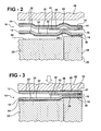
- Figure 2 is an enlarged cross-sectional view taken along lines 2-2 of Figure 1 ;
- Figure 3 is a view like Figure 2 but showing the gasket in a compressed condition
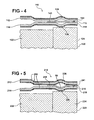
- Figure 4 is a cross-sectional view of an alternative embodiment of the invention.
- Figure 5 is a cross-sectional view of still a further alternative embodiment of the invention.
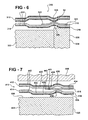
- Figure 6 is a cross-sectional view of still a further embodiment of the invention.
- Figure 7 is a cross-sectional view of still a further embodiment of the invention.
- a multilayer metal gasket constructed according to a first presently preferred embodiment of the invention is shown generally at 10 in Figures 1 and 2 and includes at least a set of first and second gasket layers 12, 14 and a partial stopper layer 16 between the gasket layers 12, 14.
- the gasket layers 12, 14 are each fabricated of elastic metal sheet material, such as stainless steel or the like, and are formed with various openings through the gasket layers, including multiple cylinder openings 18 for engine cylinders 20 of an engine block 22 which, in some engines, may be fitted with a cylinder liner 24 shown in Figure 2 .
- the cylinder opening 18 and the gasket layers 12, 14 are aligned and each gasket layer 12, 14 is formed with a respective elastic sealing bead 26, 28 that encircle the opening 18.
- the sealing beads 26, 28 are formed as deformation of the first and second gasket layers 12, 14 and comprise a ridge of gasket layer material, preferably in the shape of a full bead, which projects from a plane of a main body 30, 32 of the respective gasket layers 12, 14.
- the sealing beads 26, 28 of the first and second gasket layers 12, 14 are arranged in opposing, aligned relationship such that they oppose one another, as shown in the embodiment of Figure 2 .
- the sealing beads 26, 28 are spaced radially outwardly of the cylinder opening 18, defining radially inner land regions 34, 36 surrounding the opening 18 and separating the sealing beads 26, 28 from the opening 18.
- the land regions 34, 36 are part of the main body 30, 32 of the gasket layers 12, 14 and are preferably planar and parallel to one another.
- a rubberized gasket coating 42 may be applied to the outer exposed surfaces of the gasket layers 12, 14.
- the partial stopper layer 16 is arranged between the gasket layers 12, 14, and more specifically is interposed between the sealing beads 26, 28.
- the partial stopper layer is "partial" in the sense that it has an area considerably less than the area of either of the first or second gasket layers 12, 14. As shown in Figure 2 , the partial stopper layer 16 extends from or near the cylinder opening 18 radially outwardly to the land regions 38, 40 just beyond the sealing beads 26, 28.
- the partial stopper layer 16 is fixed, preferably by welding, to at least one and preferably only one of the first and second gasket layers 12, 14. In the first embodiment of Figure 2 , the stopper layer 16 is fixed to the first gasket layer 12 by a weld joint 41 at a location radially inward of the sealing beads 26, 28.
- An opposite outward end 43 of the stopper layer 16 is located radially outward of the sealing beads 26, 28 and in this embodiment is free and unattached to either of the adjacent layers 12, 14.
- the stopper layer is fixed at only one of its ends, preferably the radially inner end adjacent the cylinder opening 18, while the other end of the stopper layer on the opposite side of the sealing bead is unattached and free to move relative to the layer to which it is attached when the gasket 10 is clamped under compression.
- the stopper layer 16 is secured to the radially inner land region 34 of the first gasket layer 12 at a location between the cylinder opening 18 and the sealing bead 26.
- the preferred means for securing the stopper layer 16 is welding, and preferably laser welding, although other techniques may be employed, such as, but not limited to riveting, adhesives, an intermediate bonding layer, or the like.
- the partial stopper layer 16 is planar.
- the aligned sealing beads 26, 28 extend in the same direction, with the sealing bead 26 of the first layer projecting outwardly of its main body 30, and the sealing bead 28 of the second layer 14 projecting in the same direction toward the first gasket layer 12.
- the peak of the sealing bead 28 of the second layer 14 contacts the underside of the stopper layer 16 opposite the side attached to the first gasket layer 12 in the region spanning the sealing bead 26 of the first gasket layer 12.
- FIG. 3 there is illustrated a condition in which the cylinder liner 24 projects slightly above a top deck 44 of the engine block 22.
- the gasket 10 is sufficiently soft in compressibility to accommodate the projecting liner and still form a suitable seal between the block 22 and liner 24 and a cylinder head 46 that is clamped by bolting or the like to the block 22 as illustrated in Figure 3 .
- the gasket 10 is able to deform under a relatively light clamping load to bridge the step formed between the projecting cylinder liner 24 and the top deck 44 of the block 20, and on the opposite side to form a seal with the cylinder head 46 so as to seal the engine cylinder 20 from leakage.
- the stopper layer 16 With the stopper layer 16 being affixed to only one side of the sealing beads 26, the stopper layer does not overly inhibit the deformation of the sealing beads and lends to a softer, more readily compressible gasket of reduced thickness.
- the sealing beads when the gasket is compressed, the sealing beads are pressed toward a flat condition and tend to spread out, causing slight movement of the gasket layers 12, 14, shown exaggerated in Figure 3 for purposes of illustration. Any such movement or slippage of the gasket layers is not inhibited by the partial stopper layer since it is fixed on only one side of the sealing beads and is free at its opposite end 48.
- a gasket 110 constructed according to a second embodiment of the invention is shown at Figure 4 , wherein the same reference numerals are used to indicate like features that are offset by 100.
- This gasket 110 is of the same construction as that of the gasket of Figure 2 , except that the second layer 14 is reversed in its orientation, such that the sealing beads 126, 128 are each directed outwardly away from one another.
- the stopper layer 116 is fixed to the second layer 114, although it could as well be fixed to the first layer 112 instead. The same benefits described above in connection with the gasket 10 of the first embodiment are evident in the gasket 110 of the second embodiment.
- the gasket 210 constructed according to a third embodiment of the invention is shown in Figure 5 , in which the same reference numerals used in connection with the gasket 10 of the first embodiment, but are offset by 200.
- the gasket 210 is identical in construction to that of Figure 4 , except that the stopper layer 16 is preformed with a bead 50 that nests with the bead 228 of the second layer to which it is attached.
- Figure 6 illustrates a gasket 310 constructed according to a fourth embodiment of the invention, wherein the same reference numerals are used to indicate like features, but are offset by 300.
- the orientation of the first gasket layer 312 is reversed such that the sealing beads 326, 328 project inwardly toward one another, and that the stopper layer 316, joined to the second gasket layer 314 is preformed with a bead 52 that nests with the sealing bead 28 of the second layer 314.
- Figure 7 illustrates a gasket 410 constructed according to a fifth embodiment of the invention, wherein the same reference numerals are used to designate like features, but are offset by 400.
- the gasket constriction is identical to that shown in Figure 2 , except that the attachment weld 441 is located on the raidally outboard side 443 of the stopper layer outward of the beads 426, 428 instead of on the radially inward side.
- the portion of the stopper layer 416 radially inward of the beads 426, 428 is free an unattached to either layer 412, 414.
- the engine block 422 lacks a liner.
- This gasket 410 is equally applicable to engines with liners and engines without liners, as are each of the other embodiments of the invention described above. It is to be understood that within the scope of the present invention it is contemplated that the same outward location of the attachment weld 441 as shown in Figure 7 could be applied to each of the other embodiments of Figures 4-6 .
Landscapes
- Engineering & Computer Science (AREA)
- General Engineering & Computer Science (AREA)
- Mechanical Engineering (AREA)
- Gasket Seals (AREA)
Description
- This invention relates generally to multilayer metal gaskets, and particularly to those having at least two active bead layers separated by a partial stopper layer.
- Multilayer metal gaskets are commonly used in engine applications to provide a seal between two members that are joined by bolting or other clamping means, such as between a cylinder head and an engine block, or between an exhaust manifold and the block.
- Various gasket configurations are known to the art and serve a variety of purposes. A particular application to which the present invention is directed is one in which the gasket is required to be of minimal thickness and able to seal effectively under fairly low contact pressure or able to conform to protrusions or recessions at the seal interface, such as in a cylinder head application where the cylinder liner protrudes above the top sealing deck of the engine block. Under these less than ideal sealing conditions, it is difficult to construct a seal that satisfies all of the criteria that such an application calls for.
- For example,
US Patent 5,544,899 discloses a multilayer metal gasket having a pair of functional layers formed with aligned openings and aligned beads surrounding the openings. A partial stopper layer is interposed between the functional layers in surrounding relation to the openings. In some of the embodiments, the stopper layer extends only partially across the sealing beads, enabling the beads to collapse against themselves under a clamping load. The concern here is that the full collapse of the beads could cause at least some degree of overcompression and permanent deformation of the beads and thus impair the sealing performance of the gasket. In at least one other embodiment, the stopper layer spans the full width of the beads and is welded on the opposite sides as well as deformed into nesting relation with one of the two opposing beads. It will be appreciated that the stopper layer in this embodiment would serve to constrain the deformation of the gasket layer that it is joined to by being welded on opposite sides of the bead. Consequently, the constrained functional layer compresses at a much higher load than that of the other layer, and the overall compression strength of the gasket increases, making it perhaps unsuitable for those applications calling for minimal gasket thickness and low compressibility. -
US Patent 5,628,518 discloses another type of multilayer metal gasket which requires the middle layer to be a full layer rather than only a partial layer. While this may be suitable for many gasket applications, the full middle layer adds to the over all thickness of the gasket and thus may not be suitable for applications calling for minimal gasket thickness.
JP 2000 002335 A - It is an object of the present invention to overcome or greatly minimize the shortcomings of the known prior gaskets and to provide a gasket that is best suited to minimal thickness, low compression applications.
- A multilayer metal gasket constructed according to a presently preferred embodiment of the invention comprises at least a set of first and second gasket layers having generally planar bodies and formed with multiple aligned cylinder openings and associated sealing bead in each of the gasket layers aligned opposite one another and projecting out of the plane of their respective bodies in radially outwardly spaced surrounding relation to the multiple cylinder openings. The gasket further includes a partial stopper layer disposed between the gasket layers and having an area less than that of the either of the gasket layers. The stopper layer extends fully across the sealing beads from a position radially inward of the sealing beads to a position radially outward of the sealing beads and is fixed to at least one of the gasket layers adjacent only one side of the sealing beads and is free on the opposite side of the sealing beads. The partial stopper layer comprises multiple separate rings, one for each of said cylinder opening and associated sealing beads.
- One advantage of the present invention is that it provides a gasket of minimal thickness with relatively soft compressibility and controlled deformation of the sealing beads.
- By extending fully across the sealing beads, the stopper layer has the beneficial effect of providing generally uniform compression of the complete sealing bead in all layers of the gasket. Further, by being joined to only one side and being free on the opposite side of the sealing beads, the stopper layer does not overly constrain deformation of the sealing bead on the gasket layer to which the stopper layer is joined, thereby giving more uniform deformation of the sealing beads.
- These and other features and advantages of the present invention will become more readily appreciated when considered in connection with the following detailed description and appended drawings, wherein:
-
Figure 1 is a fragmentary plan view of a gasket constructed according to a presently preferred embodiment of the invention; -
Figure 2 is an enlarged cross-sectional view taken along lines 2-2 ofFigure 1 ; -
Figure 3 is a view likeFigure 2 but showing the gasket in a compressed condition; -
Figure 4 is a cross-sectional view of an alternative embodiment of the invention; -
Figure 5 is a cross-sectional view of still a further alternative embodiment of the invention; -
Figure 6 is a cross-sectional view of still a further embodiment of the invention; and -
Figure 7 is a cross-sectional view of still a further embodiment of the invention. - A multilayer metal gasket constructed according to a first presently preferred embodiment of the invention is shown generally at 10 in
Figures 1 and2 and includes at least a set of first andsecond gasket layers partial stopper layer 16 between thegasket layers gasket layers multiple cylinder openings 18 forengine cylinders 20 of anengine block 22 which, in some engines, may be fitted with acylinder liner 24 shown inFigure 2 . The cylinder opening 18 and thegasket layers gasket layer elastic sealing bead opening 18. Thesealing beads second gasket layers main body respective gasket layers sealing beads second gasket layers Figure 2 . The sealingbeads inner land regions sealing beads land regions main body gasket layers sealing beads outer land region main body inner land regions gasket coating 42 may be applied to the outer exposed surfaces of thegasket layers - The
partial stopper layer 16 is arranged between thegasket layers sealing beads second gasket layers Figure 2 , thepartial stopper layer 16 extends from or near the cylinder opening 18 radially outwardly to theland regions sealing beads partial stopper layer 16 is fixed, preferably by welding, to at least one and preferably only one of the first andsecond gasket layers Figure 2 , thestopper layer 16 is fixed to thefirst gasket layer 12 by aweld joint 41 at a location radially inward of thesealing beads outward end 43 of thestopper layer 16 is located radially outward of the sealingbeads adjacent layers Figure 2 as well as the other embodiments of the invention, it will be noted that the stopper layer is fixed at only one of its ends, preferably the radially inner end adjacent the cylinder opening 18, while the other end of the stopper layer on the opposite side of the sealing bead is unattached and free to move relative to the layer to which it is attached when thegasket 10 is clamped under compression. Specifically referring to the first embodiment ofFigure 2 , it will be seen that thestopper layer 16 is secured to the radiallyinner land region 34 of thefirst gasket layer 12 at a location between the cylinder opening 18 and thesealing bead 26. The preferred means for securing thestopper layer 16 is welding, and preferably laser welding, although other techniques may be employed, such as, but not limited to riveting, adhesives, an intermediate bonding layer, or the like. In this first embodiment, thepartial stopper layer 16 is planar. Further with this first embodiment, the alignedsealing beads bead 26 of the first layer projecting outwardly of itsmain body 30, and thesealing bead 28 of thesecond layer 14 projecting in the same direction toward thefirst gasket layer 12. The peak of thesealing bead 28 of thesecond layer 14 contacts the underside of thestopper layer 16 opposite the side attached to thefirst gasket layer 12 in the region spanning thesealing bead 26 of thefirst gasket layer 12. - Referring additionally to
Figure 3 , there is illustrated a condition in which thecylinder liner 24 projects slightly above atop deck 44 of theengine block 22. Thegasket 10 is sufficiently soft in compressibility to accommodate the projecting liner and still form a suitable seal between theblock 22 andliner 24 and acylinder head 46 that is clamped by bolting or the like to theblock 22 as illustrated inFigure 3 . Thegasket 10 is able to deform under a relatively light clamping load to bridge the step formed between the projectingcylinder liner 24 and thetop deck 44 of theblock 20, and on the opposite side to form a seal with thecylinder head 46 so as to seal theengine cylinder 20 from leakage. With thestopper layer 16 being affixed to only one side of thesealing beads 26, the stopper layer does not overly inhibit the deformation of the sealing beads and lends to a softer, more readily compressible gasket of reduced thickness. In particular, as shown inFigure 3 , when the gasket is compressed, the sealing beads are pressed toward a flat condition and tend to spread out, causing slight movement of thegasket layers Figure 3 for purposes of illustration. Any such movement or slippage of the gasket layers is not inhibited by the partial stopper layer since it is fixed on only one side of the sealing beads and is free at its opposite end 48. - A
gasket 110 constructed according to a second embodiment of the invention is shown atFigure 4 , wherein the same reference numerals are used to indicate like features that are offset by 100. Thisgasket 110 is of the same construction as that of the gasket ofFigure 2 , except that thesecond layer 14 is reversed in its orientation, such that the sealingbeads stopper layer 116 is fixed to thesecond layer 114, although it could as well be fixed to thefirst layer 112 instead. The same benefits described above in connection with thegasket 10 of the first embodiment are evident in thegasket 110 of the second embodiment. - The
gasket 210 constructed according to a third embodiment of the invention is shown inFigure 5 , in which the same reference numerals used in connection with thegasket 10 of the first embodiment, but are offset by 200. Thegasket 210 is identical in construction to that ofFigure 4 , except that thestopper layer 16 is preformed with abead 50 that nests with thebead 228 of the second layer to which it is attached. -
Figure 6 illustrates agasket 310 constructed according to a fourth embodiment of the invention, wherein the same reference numerals are used to indicate like features, but are offset by 300. In this embodiment, the orientation of thefirst gasket layer 312 is reversed such that the sealingbeads stopper layer 316, joined to thesecond gasket layer 314 is preformed with abead 52 that nests with the sealingbead 28 of thesecond layer 314. -
Figure 7 illustrates agasket 410 constructed according to a fifth embodiment of the invention, wherein the same reference numerals are used to designate like features, but are offset by 400. In this embodiment, the gasket constriction is identical to that shown inFigure 2 , except that theattachment weld 441 is located on the raidallyoutboard side 443 of the stopper layer outward of thebeads stopper layer 416 radially inward of thebeads layer Figure 7 that theengine block 422 lacks a liner. Thisgasket 410 is equally applicable to engines with liners and engines without liners, as are each of the other embodiments of the invention described above. It is to be understood that within the scope of the present invention it is contemplated that the same outward location of theattachment weld 441 as shown inFigure 7 could be applied to each of the other embodiments ofFigures 4-6 . - Obviously, many modifications and variations of the present invention are possible in light of the above teachings. It is, therefore, to be understood that within the scope of the appended claims, the invention may be practiced otherwise than as specifically described. The invention is defined by the claims.
Claims (16)
- A multilayer metal gasket (10), comprising:at least first and second gasket layers (12, 14, 312, 314) having generally planar bodies and formed with multiple aligned cylinder openings (18) and associated sealing bead (26, 28, 126, 128 326, 328) in each of the gasket layers (12, 14, 312, 314) aligned opposite one another and projecting out of the plane of their respective bodies in radially outwardly spaced surrounding relation to said multiple cylinder openings (18); anda partial stopper layer (16, 316) disposed between said gasket layers (12, 14, 312, 314) and having an area less than that of either of said gasket layers (12, 14, 312, 314), said stopper layer (16, 316) extending fully across said sealing beads (26, 28, 126, 128 326, 328) from a position radially inward of said sealing beads (26, 28, 126, 128 326, 328) to a position radially outward of said sealing beads (26, 28, 126, 128 326, 328), and being fixed to at least one of said gasket layers (12, 14, 312, 314) adjacent only one side of said sealing beads (26, 28, 126, 128 326, 328) and is free on the opposite side of the sealing beads (26, 28, 126, 128 326, 328),characterized in thatsaid partial stopper layer (16,316) comprises multiple separate rings, one for each of said cylinder opening (18) and associated sealing beads (26, 28, 126, 128 326, 328).
- The gasket of claim 1 wherein each of said separate rings of said stopper layer (16, 316) is fixed to said at least one gasket layer (12, 14, 312, 314) on the side radially inward of said associated sealing beads (26, 28, 126, 128 326, 328).
- The gasket of claim 1 wherein each of said separate rings of said stopper layer (16, 316) is fixed to only one of said gasket layers (12, 14, 312, 314).
- The gasket layer of claim 1 wherein each of said separate rings of said stopper layer (16, 316) is fixed at a radially inward end thereof.
- The gasket layer of claim 4 wherein each of said separate rings of said stopper layer (16, 316) has a radially outward end that is unattached to said gasket layers.
- The gasket of claim 1 wherein said sealing beads (26, 28, 126, 128 326, 328) project toward one another.
- The gasket of claim 6 wherein each of said separate rings of said stopper layer (16, 316) is formed with a bead that is nested with one of said associated beads of said gasket layers.
- The gasket of claim 1 wherein said sealing beads (26, 28, 126, 128 326, 328) project away from one another.
- The gasket of claim 8 wherein each of said separate rings of said stopper layer (16, 316) is planar.
- The gasket of claim 1 wherein said sealing beads (26, 28, 126, 128 326, 328) project in the same direction.
- The gasket of claim 1 wherein each of said separate rings of said stopper layer (16, 316) is planar.
- The gasket of claim 1 wherein each of said separate rings of said stopper layer (16, 316) extends radially inwardly and outwardly beyond said associated sealing beads (26, 28, 126, 128 326, 328).
- The gasket of claim 1 wherein each of said separate rings of said stopper layer (16, 316) is fixed to said at least one gasket layer (12, 14, 312, 314) on the side radially outward of said associated sealing beads (26, 28, 126, 128 326, 328).
- The gasket of claim 1 wherein each of said separate rings of said stopper layer (16, 316) is fixed at a radially outward end thereof.
- The gasket of claim 1 wherein each of said separate rings of said stopper layer (16, 316) has a radially inward end that is unattached to said gasket layers (12, 14, 312, 314).
- An assembly, comprising:an engine block having multiple cylinder openings each fitted with a cylinder liner;a cylinder head;a gasket according to any of claims 1 to 15 disposed between said engine block and said cylinder head, wherein said aligned multiple cylinder openings (18),corresponding to said cylinders (20) of said engine block, and wherein said gasket engaging said multiple cylinder liners.
Applications Claiming Priority (3)
| Application Number | Priority Date | Filing Date | Title |
|---|---|---|---|
| US54798104P | 2004-02-26 | 2004-02-26 | |
| US11/063,073 US20050189724A1 (en) | 2004-02-26 | 2005-02-22 | Metal gasket |
| PCT/US2005/005717 WO2005081957A2 (en) | 2004-02-26 | 2005-02-23 | Metal gasket having fixed partial stopper layer |
Publications (3)
| Publication Number | Publication Date |
|---|---|
| EP1740817A2 EP1740817A2 (en) | 2007-01-10 |
| EP1740817A4 EP1740817A4 (en) | 2011-03-16 |
| EP1740817B1 true EP1740817B1 (en) | 2012-10-10 |
Family
ID=34889940
Family Applications (1)
| Application Number | Title | Priority Date | Filing Date |
|---|---|---|---|
| EP05723552A Not-in-force EP1740817B1 (en) | 2004-02-26 | 2005-02-23 | Metal gasket |
Country Status (6)
| Country | Link |
|---|---|
| US (2) | US20050189724A1 (en) |
| EP (1) | EP1740817B1 (en) |
| JP (1) | JP2007525629A (en) |
| CA (1) | CA2556707A1 (en) |
| RU (1) | RU2358172C2 (en) |
| WO (1) | WO2005081957A2 (en) |
Families Citing this family (33)
| Publication number | Priority date | Publication date | Assignee | Title |
|---|---|---|---|---|
| US20050218607A1 (en) * | 2004-03-30 | 2005-10-06 | Nichias Corporation | Metal gasket |
| MX2007000602A (en) * | 2004-07-16 | 2008-10-27 | Dana Corp | Fluid aperture with stopper bead. |
| DE102005043630A1 (en) | 2005-09-13 | 2007-03-22 | Federal-Mogul Sealing Systems Gmbh | Metallic flat gasket |
| US7757653B2 (en) * | 2007-02-21 | 2010-07-20 | Ford Global Technologies, Llc | Integrated exhaust manifold and cylinder head gasket |
| US8100409B2 (en) * | 2007-09-11 | 2012-01-24 | Federal-Mogul World Wide, Inc. | Metallic cylinder head gasket |
| JP4534097B2 (en) * | 2007-09-12 | 2010-09-01 | 日本ガスケット株式会社 | Cylinder head gasket |
| JP5204550B2 (en) * | 2008-05-20 | 2013-06-05 | 国立大学法人東北大学 | Metal gasket |
| WO2009152815A1 (en) * | 2008-06-21 | 2009-12-23 | Federal-Mogul Sealing Systems Gmbh | Flat seal |
| US20100032909A1 (en) * | 2008-08-06 | 2010-02-11 | Ford Global Technologies Llc | Engine Cylinder Head Gasket Assembly |
| US20100143101A1 (en) * | 2008-12-05 | 2010-06-10 | General Electric Company | Compliant foil seal for rotary machines |
| DE102009008791A1 (en) * | 2009-02-13 | 2010-09-16 | Federal-Mogul Sealing Systems Gmbh | Flat seals with additional sealing element |
| DE102009021503B4 (en) * | 2009-05-15 | 2015-02-12 | Federal-Mogul Sealing Systems Gmbh | Flat gasket with sealing bead and embossing as well as production method thereof |
| KR101707893B1 (en) * | 2009-08-19 | 2017-02-17 | 페더럴-모걸 코오포레이숀 | Cylinder head gasket assembly |
| KR20110088248A (en) * | 2010-01-28 | 2011-08-03 | 동아공업 주식회사 | Head gasket having integrated bead and stopper and method of manufacturing the same |
| WO2011103373A1 (en) | 2010-02-19 | 2011-08-25 | Federal-Mogul Corporation | Multilayer gasket with labyrinth stopper |
| KR101936057B1 (en) | 2011-02-01 | 2019-01-08 | 페더럴-모걸 엘엘씨 | Multilayer static gasket with secondary compression limiter |
| US9695936B2 (en) * | 2011-04-14 | 2017-07-04 | Federal-Mogul Llc | Multilayer metal gasket with bead on stopper |
| US8616557B2 (en) | 2011-10-06 | 2013-12-31 | Federal-Mogul Corporation | Multilayer gasket with segmented integral stopper feature |
| US8752841B2 (en) | 2012-05-18 | 2014-06-17 | Federal-Mogul Corporation | Gasket with a compression limiter |
| US9644741B2 (en) * | 2012-06-01 | 2017-05-09 | Federal-Mogul Llc | Metal gasket |
| US9394850B2 (en) | 2012-08-10 | 2016-07-19 | Dana Automotive Systems Group, Llc | Metal gasket with coating topography |
| FR2997324B1 (en) * | 2012-10-31 | 2015-05-15 | Snecma | HIGH PERFORMANCE PERFORMING ANNULAR METAL STATIC JOINT FOR HIGH PRESSURES AND LARGE DIAMETERS |
| EP2733396A1 (en) * | 2012-11-20 | 2014-05-21 | Caterpillar Inc. | Service gasket for internal combustion engine and method |
| US9970548B2 (en) * | 2013-03-14 | 2018-05-15 | Federal-Mogul Llc | Multi-layer gasket |
| KR20160053951A (en) | 2013-09-10 | 2016-05-13 | 페더럴-모걸 코오포레이숀 | Coatingless cylinder head gasket |
| US9863535B2 (en) * | 2014-01-17 | 2018-01-09 | Federal-Mogul Llc | Gasket component with half-stop and method of manufacturing |
| US20150226153A1 (en) * | 2014-02-13 | 2015-08-13 | Federal Mogul Corporation | Cylinder head gasket for high load and motion applications |
| US11248703B2 (en) | 2014-03-18 | 2022-02-15 | Nok Corporation | Metal gasket |
| US10359003B2 (en) * | 2014-06-23 | 2019-07-23 | Tenneco Inc. | Cylinder head gasket with compression limiter and full bead loading |
| US10634251B2 (en) * | 2014-08-20 | 2020-04-28 | Tenneca Inc. | Multi-layer gasket assembly |
| JP6367177B2 (en) * | 2015-12-28 | 2018-08-01 | ニチアス株式会社 | Cylinder head gasket and stainless steel plate for cylinder head gasket |
| JP2018071730A (en) * | 2016-11-02 | 2018-05-10 | Nok株式会社 | gasket |
| US11585441B2 (en) | 2020-11-20 | 2023-02-21 | Dana Automotive Systems Group, Llc | Laser profiled gasket and method for manufacturing said gasket |
Family Cites Families (26)
| Publication number | Priority date | Publication date | Assignee | Title |
|---|---|---|---|---|
| US4799695A (en) * | 1982-05-17 | 1989-01-24 | Nihon Metal Gasket Kabushiki Kaisha | Metallic gasket |
| US4896891A (en) * | 1988-05-16 | 1990-01-30 | Ishikawa Gasket Co., Ltd. | Steel laminate gasket with associated beads |
| US5009438A (en) * | 1988-05-16 | 1991-04-23 | Ishikawa Gasket Co., Ltd. | Steel laminate gasket with associated beads |
| DE69016781T2 (en) * | 1990-05-28 | 1995-09-14 | Nihon Metal Gasket | Metal gasket. |
| DE69108628T2 (en) * | 1990-07-26 | 1995-08-31 | Taiho Kogyo Co Ltd | Metal gasket. |
| JPH0812741B2 (en) | 1990-08-27 | 1996-02-07 | 富士通株式会社 | Magnetic tape unit |
| JP3142155B2 (en) * | 1991-08-21 | 2001-03-07 | 日本ガスケット株式会社 | Metal gasket |
| JP2841250B2 (en) * | 1991-09-05 | 1998-12-24 | 日本ガスケット株式会社 | Metal gasket and manufacturing method thereof |
| DE69209009T2 (en) * | 1991-11-25 | 1996-08-29 | Taiho Kogyo Co Ltd | Metal gasket |
| JPH086805B2 (en) * | 1992-06-09 | 1996-01-29 | 日本メタルガスケット株式会社 | Metal gasket |
| JPH06117542A (en) * | 1992-10-06 | 1994-04-26 | Japan Metal Gasket Co Ltd | Metal gasket |
| JP3197395B2 (en) * | 1993-01-14 | 2001-08-13 | 日本メタルガスケット株式会社 | Metal gasket |
| JP2925920B2 (en) * | 1994-03-09 | 1999-07-28 | 本田技研工業株式会社 | Metal gasket |
| US5549307A (en) * | 1994-10-17 | 1996-08-27 | Fel-Pro Incorporated | Multi-layer metal gasket with double beaded combustion seal |
| KR980008780U (en) * | 1996-07-08 | 1998-04-30 | 김영귀 | Structure of airtightness of cylinder head |
| JP3738121B2 (en) * | 1997-11-07 | 2006-01-25 | 日本ガスケット株式会社 | Metal gasket |
| JP3314371B2 (en) * | 1999-05-10 | 2002-08-12 | 日本メタルガスケット株式会社 | Metal gasket |
| JP2001012611A (en) * | 1999-06-30 | 2001-01-16 | Nippon Gasket Co Ltd | Metal gasket |
| DE10019715B4 (en) * | 2000-04-20 | 2006-01-05 | Elringklinger Ag | Method for applying an elevation to a metal layer of a cylinder head gasket and cylinder head gasket |
| JP2002115761A (en) * | 2000-10-10 | 2002-04-19 | Nippon Gasket Co Ltd | Metal gasket |
| DE10102288C2 (en) * | 2001-01-19 | 2003-10-30 | Reinz Dichtungs Gmbh & Co Kg | Metallic flat gasket |
| DE10196542B4 (en) | 2001-03-07 | 2008-12-04 | Japan Metal Gasket Co. Ltd., Kumagaya | metal seal |
| JP4287069B2 (en) * | 2001-03-23 | 2009-07-01 | ニチアス株式会社 | Metal gasket |
| DE10213900B4 (en) * | 2002-03-28 | 2006-04-06 | Elringklinger Ag | Cylinder head gasket |
| US6935635B2 (en) * | 2002-12-12 | 2005-08-30 | Mccord Leakless Sealing Co. | Metal gasket |
| US7374177B2 (en) * | 2004-09-21 | 2008-05-20 | Federal-Mogul World Wide, Inc. | Enhanced multilayer metal gasket |
-
2005
- 2005-02-22 US US11/063,073 patent/US20050189724A1/en not_active Abandoned
- 2005-02-23 RU RU2006134009/06A patent/RU2358172C2/en not_active IP Right Cessation
- 2005-02-23 JP JP2007500941A patent/JP2007525629A/en active Pending
- 2005-02-23 EP EP05723552A patent/EP1740817B1/en not_active Not-in-force
- 2005-02-23 WO PCT/US2005/005717 patent/WO2005081957A2/en active Application Filing
- 2005-02-23 CA CA002556707A patent/CA2556707A1/en not_active Abandoned
-
2011
- 2011-04-21 US US13/091,191 patent/US8556271B2/en not_active Expired - Fee Related
Also Published As
| Publication number | Publication date |
|---|---|
| EP1740817A2 (en) | 2007-01-10 |
| CA2556707A1 (en) | 2005-09-09 |
| WO2005081957A2 (en) | 2005-09-09 |
| RU2358172C2 (en) | 2009-06-10 |
| EP1740817A4 (en) | 2011-03-16 |
| US8556271B2 (en) | 2013-10-15 |
| US20050189724A1 (en) | 2005-09-01 |
| JP2007525629A (en) | 2007-09-06 |
| RU2006134009A (en) | 2008-04-10 |
| US20110192369A1 (en) | 2011-08-11 |
| WO2005081957A3 (en) | 2006-12-14 |
Similar Documents
| Publication | Publication Date | Title |
|---|---|---|
| EP1740817B1 (en) | Metal gasket | |
| US6758479B2 (en) | Cylinder head gasket with different materials | |
| US8733763B2 (en) | Gasket assembly having isolated compression limiting device | |
| US6786490B2 (en) | Metal gasket | |
| US20090184478A1 (en) | Metal gasket | |
| US6457724B2 (en) | Metallic gasket | |
| US6588765B2 (en) | Monolayer metal gaskets | |
| US20060017232A1 (en) | Metal gasket | |
| US6502829B2 (en) | Gasket-squeeze construction | |
| EP2697541B1 (en) | Multilayer metal gasket with bead on stopper | |
| JPH11118038A (en) | Metal gasket | |
| US7793942B2 (en) | Metal gasket | |
| JP4110256B2 (en) | Metal gasket | |
| US6969072B2 (en) | Cylinder head gasket with fold-over stopper | |
| MXPA06009735A (en) | Metal gasket | |
| JP2990291B2 (en) | Cylinder head gasket | |
| JP2001032938A (en) | Metal gasket | |
| JP3363208B2 (en) | Metal gasket | |
| JP3467062B2 (en) | Metal gasket | |
| JP2002323135A (en) | Single-layer metal gasket | |
| JPH0562670B2 (en) | ||
| JPH08291864A (en) | Metal gasket | |
| JPH066829U (en) | Metal laminated gasket | |
| JP2001200755A (en) | Gasket | |
| JP2005090572A (en) | Sealing structure |
Legal Events
| Date | Code | Title | Description |
|---|---|---|---|
| PUAI | Public reference made under article 153(3) epc to a published international application that has entered the european phase |
Free format text: ORIGINAL CODE: 0009012 |
|
| PUAK | Availability of information related to the publication of the international search report |
Free format text: ORIGINAL CODE: 0009015 |
|
| 17P | Request for examination filed |
Effective date: 20060825 |
|
| AK | Designated contracting states |
Kind code of ref document: A2 Designated state(s): AT BE BG CH CY CZ DE DK EE ES FI FR GB GR HU IE IS IT LI LT LU MC NL PL PT RO SE SI SK TR |
|
| AX | Request for extension of the european patent |
Extension state: AL BA HR LV MK YU |
|
| DAX | Request for extension of the european patent (deleted) | ||
| RBV | Designated contracting states (corrected) |
Designated state(s): DE ES FR GB IT |
|
| A4 | Supplementary search report drawn up and despatched |
Effective date: 20110216 |
|
| 17Q | First examination report despatched |
Effective date: 20110420 |
|
| RIC1 | Information provided on ipc code assigned before grant |
Ipc: F02F 11/00 20060101AFI20120411BHEP Ipc: F16J 15/08 20060101ALI20120411BHEP |
|
| GRAP | Despatch of communication of intention to grant a patent |
Free format text: ORIGINAL CODE: EPIDOSNIGR1 |
|
| GRAS | Grant fee paid |
Free format text: ORIGINAL CODE: EPIDOSNIGR3 |
|
| GRAA | (expected) grant |
Free format text: ORIGINAL CODE: 0009210 |
|
| AK | Designated contracting states |
Kind code of ref document: B1 Designated state(s): DE ES FR GB IT |
|
| REG | Reference to a national code |
Ref country code: GB Ref legal event code: FG4D |
|
| REG | Reference to a national code |
Ref country code: DE Ref legal event code: R096 Ref document number: 602005036485 Country of ref document: DE Effective date: 20121213 |
|
| PG25 | Lapsed in a contracting state [announced via postgrant information from national office to epo] |
Ref country code: ES Free format text: LAPSE BECAUSE OF FAILURE TO SUBMIT A TRANSLATION OF THE DESCRIPTION OR TO PAY THE FEE WITHIN THE PRESCRIBED TIME-LIMIT Effective date: 20130121 |
|
| PLBE | No opposition filed within time limit |
Free format text: ORIGINAL CODE: 0009261 |
|
| STAA | Information on the status of an ep patent application or granted ep patent |
Free format text: STATUS: NO OPPOSITION FILED WITHIN TIME LIMIT |
|
| 26N | No opposition filed |
Effective date: 20130711 |
|
| REG | Reference to a national code |
Ref country code: DE Ref legal event code: R097 Ref document number: 602005036485 Country of ref document: DE Effective date: 20130711 |
|
| PGFP | Annual fee paid to national office [announced via postgrant information from national office to epo] |
Ref country code: GB Payment date: 20140128 Year of fee payment: 10 |
|
| GBPC | Gb: european patent ceased through non-payment of renewal fee |
Effective date: 20150223 |
|
| REG | Reference to a national code |
Ref country code: FR Ref legal event code: PLFP Year of fee payment: 12 |
|
| PG25 | Lapsed in a contracting state [announced via postgrant information from national office to epo] |
Ref country code: GB Free format text: LAPSE BECAUSE OF NON-PAYMENT OF DUE FEES Effective date: 20150223 |
|
| PGFP | Annual fee paid to national office [announced via postgrant information from national office to epo] |
Ref country code: IT Payment date: 20160210 Year of fee payment: 12 |
|
| PGFP | Annual fee paid to national office [announced via postgrant information from national office to epo] |
Ref country code: FR Payment date: 20160125 Year of fee payment: 12 |
|
| REG | Reference to a national code |
Ref country code: FR Ref legal event code: ST Effective date: 20171031 |
|
| PG25 | Lapsed in a contracting state [announced via postgrant information from national office to epo] |
Ref country code: FR Free format text: LAPSE BECAUSE OF NON-PAYMENT OF DUE FEES Effective date: 20170228 |
|
| PG25 | Lapsed in a contracting state [announced via postgrant information from national office to epo] |
Ref country code: IT Free format text: LAPSE BECAUSE OF NON-PAYMENT OF DUE FEES Effective date: 20170223 |
|
| PGFP | Annual fee paid to national office [announced via postgrant information from national office to epo] |
Ref country code: DE Payment date: 20200115 Year of fee payment: 16 |
|
| REG | Reference to a national code |
Ref country code: DE Ref legal event code: R119 Ref document number: 602005036485 Country of ref document: DE |
|
| PG25 | Lapsed in a contracting state [announced via postgrant information from national office to epo] |
Ref country code: DE Free format text: LAPSE BECAUSE OF NON-PAYMENT OF DUE FEES Effective date: 20210901 |