EP2905515B1 - Gasket - Google Patents
Gasket Download PDFInfo
- Publication number
- EP2905515B1 EP2905515B1 EP13843332.1A EP13843332A EP2905515B1 EP 2905515 B1 EP2905515 B1 EP 2905515B1 EP 13843332 A EP13843332 A EP 13843332A EP 2905515 B1 EP2905515 B1 EP 2905515B1
- Authority
- EP
- European Patent Office
- Prior art keywords
- gasket
- seal
- core member
- seal portion
- deformable
- Prior art date
- Legal status (The legal status is an assumption and is not a legal conclusion. Google has not performed a legal analysis and makes no representation as to the accuracy of the status listed.)
- Active
Links
- 239000013013 elastic material Substances 0.000 claims description 11
- 238000009751 slip forming Methods 0.000 claims description 8
- 238000007789 sealing Methods 0.000 claims 1
- 238000012986 modification Methods 0.000 description 37
- 230000004048 modification Effects 0.000 description 37
- XLYOFNOQVPJJNP-UHFFFAOYSA-N water Substances O XLYOFNOQVPJJNP-UHFFFAOYSA-N 0.000 description 14
- 239000000498 cooling water Substances 0.000 description 12
- 230000000694 effects Effects 0.000 description 11
- 239000000463 material Substances 0.000 description 8
- 239000002184 metal Substances 0.000 description 7
- 239000007788 liquid Substances 0.000 description 3
- 239000007937 lozenge Substances 0.000 description 3
- 238000004073 vulcanization Methods 0.000 description 3
- 238000004891 communication Methods 0.000 description 2
- 230000006835 compression Effects 0.000 description 2
- 238000007906 compression Methods 0.000 description 2
- 230000002401 inhibitory effect Effects 0.000 description 2
- 238000002347 injection Methods 0.000 description 2
- 239000007924 injection Substances 0.000 description 2
- 239000000314 lubricant Substances 0.000 description 2
- 238000012423 maintenance Methods 0.000 description 2
- 230000000149 penetrating effect Effects 0.000 description 2
- 230000002093 peripheral effect Effects 0.000 description 2
- 238000006243 chemical reaction Methods 0.000 description 1
- 230000008878 coupling Effects 0.000 description 1
- 238000010168 coupling process Methods 0.000 description 1
- 238000005859 coupling reaction Methods 0.000 description 1
- 230000009977 dual effect Effects 0.000 description 1
- 238000004519 manufacturing process Methods 0.000 description 1
- 230000013011 mating Effects 0.000 description 1
- 238000000034 method Methods 0.000 description 1
- 238000000465 moulding Methods 0.000 description 1
- 238000003825 pressing Methods 0.000 description 1
- 238000012545 processing Methods 0.000 description 1
- 238000004080 punching Methods 0.000 description 1
- 239000011347 resin Substances 0.000 description 1
- 229920005989 resin Polymers 0.000 description 1
- 239000000243 solution Substances 0.000 description 1
- 238000003466 welding Methods 0.000 description 1
Images


Classifications
-
- F—MECHANICAL ENGINEERING; LIGHTING; HEATING; WEAPONS; BLASTING
- F16—ENGINEERING ELEMENTS AND UNITS; GENERAL MEASURES FOR PRODUCING AND MAINTAINING EFFECTIVE FUNCTIONING OF MACHINES OR INSTALLATIONS; THERMAL INSULATION IN GENERAL
- F16L—PIPES; JOINTS OR FITTINGS FOR PIPES; SUPPORTS FOR PIPES, CABLES OR PROTECTIVE TUBING; MEANS FOR THERMAL INSULATION IN GENERAL
- F16L19/00—Joints in which sealing surfaces are pressed together by means of a member, e.g. a swivel nut, screwed on or into one of the joint parts
- F16L19/02—Pipe ends provided with collars or flanges, integral with the pipe or not, pressed together by a screwed member
- F16L19/0212—Pipe ends provided with collars or flanges, integral with the pipe or not, pressed together by a screwed member using specially adapted sealing means
- F16L19/0225—Pipe ends provided with collars or flanges, integral with the pipe or not, pressed together by a screwed member using specially adapted sealing means without sealing rings
-
- F—MECHANICAL ENGINEERING; LIGHTING; HEATING; WEAPONS; BLASTING
- F16—ENGINEERING ELEMENTS AND UNITS; GENERAL MEASURES FOR PRODUCING AND MAINTAINING EFFECTIVE FUNCTIONING OF MACHINES OR INSTALLATIONS; THERMAL INSULATION IN GENERAL
- F16J—PISTONS; CYLINDERS; SEALINGS
- F16J15/00—Sealings
- F16J15/02—Sealings between relatively-stationary surfaces
- F16J15/06—Sealings between relatively-stationary surfaces with solid packing compressed between sealing surfaces
- F16J15/10—Sealings between relatively-stationary surfaces with solid packing compressed between sealing surfaces with non-metallic packing
- F16J15/104—Sealings between relatively-stationary surfaces with solid packing compressed between sealing surfaces with non-metallic packing characterised by structure
-
- F—MECHANICAL ENGINEERING; LIGHTING; HEATING; WEAPONS; BLASTING
- F16—ENGINEERING ELEMENTS AND UNITS; GENERAL MEASURES FOR PRODUCING AND MAINTAINING EFFECTIVE FUNCTIONING OF MACHINES OR INSTALLATIONS; THERMAL INSULATION IN GENERAL
- F16J—PISTONS; CYLINDERS; SEALINGS
- F16J15/00—Sealings
- F16J15/02—Sealings between relatively-stationary surfaces
- F16J15/021—Sealings between relatively-stationary surfaces with elastic packing
- F16J15/022—Sealings between relatively-stationary surfaces with elastic packing characterised by structure or material
-
- F—MECHANICAL ENGINEERING; LIGHTING; HEATING; WEAPONS; BLASTING
- F16—ENGINEERING ELEMENTS AND UNITS; GENERAL MEASURES FOR PRODUCING AND MAINTAINING EFFECTIVE FUNCTIONING OF MACHINES OR INSTALLATIONS; THERMAL INSULATION IN GENERAL
- F16J—PISTONS; CYLINDERS; SEALINGS
- F16J15/00—Sealings
- F16J15/02—Sealings between relatively-stationary surfaces
- F16J15/06—Sealings between relatively-stationary surfaces with solid packing compressed between sealing surfaces
- F16J15/061—Sealings between relatively-stationary surfaces with solid packing compressed between sealing surfaces with positioning means
-
- F—MECHANICAL ENGINEERING; LIGHTING; HEATING; WEAPONS; BLASTING
- F16—ENGINEERING ELEMENTS AND UNITS; GENERAL MEASURES FOR PRODUCING AND MAINTAINING EFFECTIVE FUNCTIONING OF MACHINES OR INSTALLATIONS; THERMAL INSULATION IN GENERAL
- F16J—PISTONS; CYLINDERS; SEALINGS
- F16J15/00—Sealings
- F16J15/02—Sealings between relatively-stationary surfaces
- F16J15/06—Sealings between relatively-stationary surfaces with solid packing compressed between sealing surfaces
- F16J15/10—Sealings between relatively-stationary surfaces with solid packing compressed between sealing surfaces with non-metallic packing
- F16J15/102—Sealings between relatively-stationary surfaces with solid packing compressed between sealing surfaces with non-metallic packing characterised by material
-
- F—MECHANICAL ENGINEERING; LIGHTING; HEATING; WEAPONS; BLASTING
- F16—ENGINEERING ELEMENTS AND UNITS; GENERAL MEASURES FOR PRODUCING AND MAINTAINING EFFECTIVE FUNCTIONING OF MACHINES OR INSTALLATIONS; THERMAL INSULATION IN GENERAL
- F16J—PISTONS; CYLINDERS; SEALINGS
- F16J15/00—Sealings
- F16J15/02—Sealings between relatively-stationary surfaces
- F16J15/06—Sealings between relatively-stationary surfaces with solid packing compressed between sealing surfaces
- F16J15/10—Sealings between relatively-stationary surfaces with solid packing compressed between sealing surfaces with non-metallic packing
- F16J15/12—Sealings between relatively-stationary surfaces with solid packing compressed between sealing surfaces with non-metallic packing with metal reinforcement or covering
- F16J15/121—Sealings between relatively-stationary surfaces with solid packing compressed between sealing surfaces with non-metallic packing with metal reinforcement or covering with metal reinforcement
- F16J15/122—Sealings between relatively-stationary surfaces with solid packing compressed between sealing surfaces with non-metallic packing with metal reinforcement or covering with metal reinforcement generally parallel to the surfaces
-
- F—MECHANICAL ENGINEERING; LIGHTING; HEATING; WEAPONS; BLASTING
- F16—ENGINEERING ELEMENTS AND UNITS; GENERAL MEASURES FOR PRODUCING AND MAINTAINING EFFECTIVE FUNCTIONING OF MACHINES OR INSTALLATIONS; THERMAL INSULATION IN GENERAL
- F16J—PISTONS; CYLINDERS; SEALINGS
- F16J15/00—Sealings
- F16J15/02—Sealings between relatively-stationary surfaces
- F16J15/06—Sealings between relatively-stationary surfaces with solid packing compressed between sealing surfaces
- F16J15/10—Sealings between relatively-stationary surfaces with solid packing compressed between sealing surfaces with non-metallic packing
- F16J15/12—Sealings between relatively-stationary surfaces with solid packing compressed between sealing surfaces with non-metallic packing with metal reinforcement or covering
- F16J15/121—Sealings between relatively-stationary surfaces with solid packing compressed between sealing surfaces with non-metallic packing with metal reinforcement or covering with metal reinforcement
- F16J15/127—Sealings between relatively-stationary surfaces with solid packing compressed between sealing surfaces with non-metallic packing with metal reinforcement or covering with metal reinforcement the reinforcement being a compression stopper
-
- F—MECHANICAL ENGINEERING; LIGHTING; HEATING; WEAPONS; BLASTING
- F16—ENGINEERING ELEMENTS AND UNITS; GENERAL MEASURES FOR PRODUCING AND MAINTAINING EFFECTIVE FUNCTIONING OF MACHINES OR INSTALLATIONS; THERMAL INSULATION IN GENERAL
- F16L—PIPES; JOINTS OR FITTINGS FOR PIPES; SUPPORTS FOR PIPES, CABLES OR PROTECTIVE TUBING; MEANS FOR THERMAL INSULATION IN GENERAL
- F16L23/00—Flanged joints
- F16L23/16—Flanged joints characterised by the sealing means
- F16L23/18—Flanged joints characterised by the sealing means the sealing means being rings
Definitions
- the present invention relates to a gasket provided at a connection portion of a flow path so as not to mix cooling water in the flow path and oil charged in a chain chamber, when the flow path of cooling water of a water jacket is provided so as to penetrate the chain chamber of an automobile engine.
- a flow path of cooling water of a water jacket sometimes has to be provided so as to penetrate a chain chamber because of a layout structure of an engine and a radiator of an automobile engine (for example, referring to Patent Literatures 1 to 3).
- a chain case is provided with a flow pipe line connected to a flow pipe of the radiator.
- the flow pipe line of the chain case communicates with a flow port of the water jacket.
- the flow path communicating the flow port with the flow path line is provided.
- a joined portion of the flow port and the flow pipe line is positioned in the chain chamber and is provided with a seal member such as an O-ring or a gasket so as to prevent cooling water from leaking to the chain chamber from the flow path and to prevent oil from flowing into the flow path from the chain chamber.
- a seal member such as an O-ring or a gasket
- Patent Literature 1 discloses that a liquid gasket is provided for the joined portion.
- Patent Literature 2 discloses that two O-rings are concentrically provided for the joined portion, an inner O-ring is used for preventing leakage of cooling water and an outer O-ring is used for preventing leakage of oil.
- Patent Literature 3 discloses that a sheet-like seal member having an inner water-proof seal portion and an outer oil seal portion is provided for the joined portion. These embodiments prevent leakage of cooling water into the chain chamber and flowing of oil into the flow path at the joined portion in the chain chamber.
- Patent Literature 4 discloses a gasket provided for a joined face of a connection portion of gas piping, not for an automobile engine, the gasket comprising a sheet-like gasket at an inner circumference and a sheet-like gasket at an outer circumference.
- Patent Literature 5 describes a gasket 1 in which a reinforced core member 2 is entirely covered with a rubber material 3.
- the gasket 1 has a seal projection 13 formed around the periphery of a through-hole 4 in addition to an inner seal projection 11 and an outer seal projection 12.
- Patent Literature 6 describes a seal and coupling, wherein the seal comprises a retainer 22 with radially inner and outer peripheral portions 28, 30 including a inner seal element 24 that provides both a face and radial seal, and an outer seal element 26 that provides a face seal.
- Patent Literature 1 when a chain case is removed for maintenance (exchange of a chain) in the chain chamber, it is bothersome to remove a coated liquid gasket and coat a liquid gasket again.
- Patent Literature 2 two kinds of O-rings are required to be prepared and to be mounted to ring grooves, respectively, in case of fastening a chain case or of the above-mentioned maintenance.
- Patent Literature 3 nuts are screwed from outside of the chain case to a pair of stud bolts provided for a side wall portion at the front end around a cooling water outlet of the cylinder head, respectively, thereby a joined portion is formed between the side wall portion at the front end and a water communication pipe of the chain case.
- the seal member (gasket) is provided for the joined portion in a compressed condition, and the cooling water outlet and the water communication pipe are communicated, thereby constituting an outlet path of cooling water.
- a base body of the seal member is considered to be constituted with a sheet-like member. Therefore, when an attachment portion (a joined portion) causes heat expansion due to the heat generated at the time of operating an engine or distortion at the time of fastening with a bolt and a nut, the base body does not follow the heat expansion or the distortion, so that the seal ability of the joined portion may be deteriorated.
- Patent Literature 4 comprises the sheet-like gasket at the inner circumference and the sheet-like gasket at the outer circumference and is provided between a pair of flanges fastened with a bolt and a nut under compression.
- Patent Literature 4 does not specifically refer to a problem such as heat expansion or distortion of the flange portion.
- Patent literature 6 discloses a seal constituting a gasket according to the preamble of claim 1.
- the present invention is proposed in view of the above-mentioned problems and has an object to provide a gasket capable of keeping seal ability of the inner seal portion and the outer seal portion and capable of inhibiting influence over the seal ability caused by heat expansion or distortion of an attachment face.
- a gasket of the embodiment of the present invention has a core member having an opening, an inner seal portion made of elastic material and formed along an inner circumference of the opening, and an outer seal portion made of elastic material and formed along an outer circumference of the core member.
- the core member has a seal-forming thin portion and an easily-deformable portion, the seal-forming thin portion being configured to form the inner seal portion at the inner circumference and to form the outer seal portion at the outer circumference, and the easily-deformable portion being provided between the inner seal portion and the outer seal portion and being configured to easily deform the core member.
- the inner circumference of the opening is sealed by the inner seal portion, thereby preventing an objective medium to be sealed flowing through the opening from leaking to an outer circumferential side.
- the outer circumference is sealed by the outer seal portion, thereby preventing another objective medium to be sealed flowing outside of the outer circumference from flowing into the opening.
- the structure is simple and the handling is easy, though a dual seal structure is constituted by only one gasket. Further, with the easily-deformable portion in the sheet-like core member, the sheet-like core member deforms in accordance with heat expansion or distortion of the attachment face (a flange face, for example) to which the gasket is attached and absorbs the heat expansion or the distortion, thereby the gasket is flexibly applied and keeps the seal ability.
- the inner seal portion and the outer seal portion to which high surface pressure is applied while being provided between the two objective members to be sealed are remarkably affected by the attachment face.
- such influence is absorbed by deformation of the easily-deformable portion provided between the inner seal portion and the outer seal portion and is inhibited to be transferred to the other seal portion, thereby keeping the seal ability.
- the easily-deformable portion of the gasket of one embodiment of the present invention can have a thin portion or a through hole.
- the sheet-like core member following the heat expansion or distortion as mentioned above is effectively deformed because of the thin portion or the through hole and influence over the seal ability in the inner seal portion and the outer seal portion is inhibited.
- the sheet-like core member made of metal, can be easily produced together with the thin portion or the through hole by a sheet-metal processing, thereby reducing the weight of the sheet-like core member.
- either the thin portion or the through hole can be continuously formed with the seal-forming thin portion of the inner seal portion and the seal-forming thin portion of the outer seal portion.
- the thin portion or the through hole is continuously formed with the seal-forming thin portion, so that the core member is easily processed.
- the thin portion or the through hole is connected with the seal-forming thin portion, thereby the sheet-like core member is easily deformed following the heat expansion and the distortion of the attachment face of the sheet-like core member.
- either the thin portion or the through hole can have a joint portion made of elastic material, the joint portion being configured to be joined with the inner seal portion and the outer seal portion.
- the inner seal portion and the outer seal portion are constituted with a rubber molded body
- the inner seal portion and the outer seal portion when rubber material is injected into an injection port with the sheet-like core member processed in a predetermined shape and positioned in a cavity of a mold, the inner seal portion and the outer seal portion can be simultaneously molded via the joint portion even if there is only one injection port.
- a plurality of fastening bolt holes are provided between the inner seal portion and the outer seal portion.
- a seal portion is not required to be provided around the fastening bolt hole because the inner and the outer seal portions are provided.
- the easily-deformable portion can be independently formed from the fastening bolt holes.
- the deformation of the easily-deformable portion does not affect the fixing function of the objective member to be sealed and the gasket in case of fastening with a bolt, thereby exerting the above-mentioned seal ability of the gasket of the embodiment of the present invention.
- the easily-deformable portion can be formed between the fastening bolt holes.
- the easily-deformable portion is provided for a position apart from the fastening bolt holes, fastening of the bolts causes stress at the position, thereby the gasket can be flexibly adapted to heat expansion or distortion on the attachment face in the embodiment.
- the influence is inhibited from being transferred to the other portion, thereby keeping the seal ability.
- the easily-deformable portion can be formed between the inner seal portion and the fastening bolt hole or between the outer seal potion and the fastening bolt hole.
- the easily-deformable portion is provided for a position apart from the fastening bolt holes, fastening of the bolts causes stress at the position, thereby the gasket can be flexibly adapted to the heat expansion or the distortion on the attachment face in the embodiment.
- the influence caused by fastening with a bolt is inhibited from being transferred to the other portion, thereby keeping the seal ability.
- the easily-deformable portion can be formed at a plurality of regions of the core member.
- the above-mentioned embodiment can be appropriately adapted even when there are a plurality of portions in which heat expansion or distortion is easily generated.
- the gasket of the embodiment of the present invention can appropriately keep seal ability of the inner seal portion and the outer seal portion with a simple structure.
- the sheet-like core member of the gasket has the easily-deformable portion, thereby effectively inhibiting influence over the seal ability, caused by heat expansion or distortion of the attachment face.
- a gasket 10 of the embodiment of the present invention is provided for a connection portion 5 of a drain path 4 (flow path) penetrating a chain case 3, i.e. a front cover, to a radiator (not shown) from a water jacket 2 provided for a cylinder block 1 of an automobile engine.
- a drain port 2a of the water jacket 2 is provided for the cylinder block 1 and a pipe 41 on the cylinder block 1 side is provided for the drain port 2a.
- a flange portion 51 is provided at the leading end of the pipe 41.
- the peripheral portion of the chain case 3 is fixed to the front side of the cylinder block 1 with a bolt, not shown, and a chain chamber 30 is formed between the chain case 3 and the front wall 1a (water jacket wall) of the cylinder block 1.
- a chain or a timing belt, not shown, for transmitting power from a crank shaft to another auxiliary machine is provided in the chain chamber 30.
- Lubricant oil, not shown, is filled in the chain chamber 30 for smoothly transmitting power with a chain and the like.
- a pipe 42 on the chain case 3 side is provided so as to penetrate the chain case 3 at a position corresponding to the pipe line 41 on the cylinder block 1 side.
- a flange portion 52, facing the flange portion 51 on the cylinder block 1 side, is formed on the base side of the pipe 42, on the cylinder block 1 side, thereby constituting the connection portion 5 with both flange portions 51, 52.
- the flange portions 51, 52 are substantially in the form of a lozenge with circular angles.
- the flange portion 51 on the cylinder block 1 side has two bolt holes 51a, 51a in the vicinity of two facing angles on diagonal lines of the lozenge with greater length.
- Two bolt holes 52a, 52a are provided for the flange portion 52 on the chain case 3 side so as to penetrate the chain case 3 while communicating with bolt holes 3a, 3a of the chain case 3 at positions corresponding to the bolt holes 51a, 51a.
- Two bolts 6, 6 for forming a drain path are screwed from the outside of the chain case 3 through the bolt holes 3a, 3a of the chain case 3, the bolt hole 52a of the flange portion 52 and the bolt hole 51a of the flange portion 51, to two female screw portions 1b, 1b provided on the bottom side of the bolt hole 51a of the front wall 1a of the cylinder block 1.
- the gasket 10 of the embodiment of the present invention is provided under pressure between the mating faces of the flange portions 51, 52.
- the pipes 41, 42 are connected via the flange portions 51, 52 and a drain path 4 is formed from the drain port 2a of the water jacket 2 to the radiator, not shown.
- a stud bolt, not shown, can be fixed to the front wall 1a of the cylinder block 1 and a nut, not shown, can be screwed to the stud bolt from the outside of the chain case 3, without using the bolts 6, 6 for forming a drain path shown in the figure.
- the drain side of the water jacket 2 is exemplified; however, the above-mentioned structure can be provided for a water supply side.
- the pipe 42 including the flange portion 52 extending into the cylinder block 1 side is provided for the chain case 3 in a projecting manner.
- the drain path 4 can be formed without having such a projecting pipe 42.
- the drain path 4 is integrally provided on the outer side of the chain case 3.
- another pipe can be provided on the outer side of the chain case 3 so as to be watertightly connected with the drain path 4.
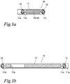
- the first embodiment of the gasket provided for the connection portion 5 is explained also referring to Fig.2 , Fig.3a and Fig.3b .
- Fig.4 to Fig. 9 show modifications of the first embodiment.
- an easily-deformable portion 15 is constituted with a thin portion 16 of the core member 11 in the form of a sheet.
- the gasket 10 of the first embodiment shown in Fig.2 , Fig.3a and Fig.3b has the core member 11 having an opening 11a, an inner seal portion 12 made of elastic material and formed along the inner circumference of the opening 11a, and an outer seal portion 13 made of elastic material and formed along the outer circumference of the core member 11.
- the elastic material of the inner seal portion 12 and the outer seal portion 13 is rubber.
- the core member 11 is a metal plate and the outer shape is substantially lozenged in conformity with the outer shape of the flange portions 51, 52.
- the opening 11a is circular of which center is concentric with the intersection of diagonal lines of the lozenge outer shape and the circular shape is substantially in conformity with the sectional shape of the drain path 4.
- the core member 11 has fastening bolt holes 11b, 11b at positions corresponding to the bolt holes 51a, 52a of the flange portions 51, 52.
- the outer shape of the core member 11, the opening 11a and the fastening bolt holes 11b, 11b are formed by a punching process.
- the core member 11 in the form of a sheet has seal-forming thin portions 11c, 11d for forming the inner seal portion 12 and the outer seal portion 13.
- the core member 11 further has an easily-deformable portion 15 for facilitating deformation of the core member 11 between the inner and the outer seal portions 12, 13.
- the easily-deformable portions 15 in this embodiment is constituted with the thin portion 16 continuously formed with the inner seal-forming thin portion 11c and the outer seal-forming thin portions 11d so as to have the same thickness thereof.
- the thin portion 16 is formed at two middle portions between the fastening bolt holes 11b, 11b independently from the fastening bolt holes 11b, 11b, namely the thin portion 16 is provided at a position which does not affect the fastening bolt holes 11b, 11b.
- the thin portion 16 is continuously formed from the seal-forming thin portions 11c, 11d, respectively.
- the thin portions 11c, 11d, 15, 15 are formed by pressing the original metal sheet of the core member 11 from both sides.
- the core member processed in a predetermined form is provided in a cavity of a mold, unvulcanized rubber material is injected, and molded by vulcanization. Then, the inner seal portion 12 and the outer seal portion 13 are integrally formed with the seal-forming thin portions 11c, 11d so as to cover the circumference thereof on the front face and the back face.
- Elastic material of the seal portions 12, 13 can be soft resin in addition to rubber material.
- the inner seal portion 12 and the outer seal portion 13 can be integrally formed on the front face and the back face of the seal-forming thin portions 11c, 11d separately so as not to cover the circumference thereof.
- the above-mentioned gasket 10 is provided under pressure between the flange portions 51, 52 of the connection portion 5 by fastening a bolt, not shown, at the periphery of the chain case 3 and the two bolts 6 for forming a drain path to the cylinder block 1, as shown in Fig.1 .
- the chain chamber 30 is formed between the chain case 3 and the front wall 1a of the cylinder block 1 by attaching the chain case 3 with the bolt and lubricant oil, not shown, is filled in the chain chamber 30.
- the drain path 4 is formed by connecting the flange portions 51, 52 interposing the gasket 10. Cooling water flows though the drain path 4 from the water jacket 2 to the radiator, not shown.
- the inner seal portion 12 and the outer seal portion 13 are compressed in the thickness direction of the core member 11 in the form of a sheet and contact under pressure the opposing faces of the flange portions 51, 52 by the reaction force. Cooling water, not shown, flowing in the drain path 4 is prevented from leaking out of the chain chamber 30 through the connection portion 5. Oil charged in the chain chamber 30 is prevented from flowing to the drain path 4 from the connection portion 5 because of the outer seal portion 13 contacting under pressure the opposing faces of the flange portions 51, 52.
- connection portion 5 of the pipes 41, 42 is provided in the chain chamber 30, oil in the chain chamber 30 and cooling water flowing in the drain path 4 are surely prevented from being mixed, thereby increasing variation of the layout structure of an engine.
- the core member 11 in the form of a sheet has the easily-deformable portion 15 constituted with the thin portion 16 and correspondingly deforms even if the flange portions 51, 52 generate heat expansion or distortion, thereby the seal ability of the inner seal portion 12 and the outer seal portion 13 is not affected.
- the easily-deformable portion 15 is provided around the middle between the fastening bolt holes 11b, 11b, so that the distance between the inner and the outer seal portions 11c, 11d is smallest, thereby effectively achieving the above-mentioned deformation.
- Fixing function of the flange portions 51, 52 via the gasket 10 by being fastened with the bolts 6, 6 for forming a drain path is not affected by deformation of the easily-deformable portion 15 because the easily-deformable portion 15 is formed in a position other than the fastening bolt holes 11b, 11b, thereby accurately keeping the seal ability.
- a portion in the vicinity of the fastening bolt holes 11b, 11b is made of rigid material so as to keep the axial force of the bolts 6, 6 for forming a drain path and the fastening bolt holes 11b, 11b are formed between the inner and the outer seal portions 12, 13, thereby the easily-deformable portion 15 effectively achieves the above-mentioned effects.
- Fig.4a, Fig.4b and Fig.4c show a modification of the gasket of the first embodiment.
- the whole shape of a gasket 10A, the inner and outer seal-forming thin portions 11c, 11d, the inner and the outer seal portions 12, 13 and the thin portion 16 constituting the easily-deformable portion 15 of the gasket 10A in the modification are formed in the same manner as those of the gasket 10 shown in Fig.2 and Fig.3 .
- the gasket 10A is different from the gasket 10 in that a joint portion 14 made of elastic material and connected with the inner seal portion 12 and the outer seal portion 13 is provided on both sides of the thin portion 16, namely the easily-deformable portion 15.
- the joint portion 14 is made of rubber material like the inner seal portion 12 and the outer seal portion 13. In case of vulcanization molding as mentioned above, unvulcanized rubber is injected from one port and the inner seal portion 12 and the outer seal portion 13 are simultaneously molded by vulcanization via the joint portion 14. In this case, the joint portion 14 is molded so as to have thickness smaller than that of the tops of the inner seal portion 12 and the outer seal portion 13.
- the inner seal portion 12 and the outer seal portion 13, being connected via the joint portion 14, are integrally fixed with the core member 11 in the form of a sheet and are restrained by the core member 11, thereby achieving the seal ability independently without being affected by the deformation caused by the above-mentioned compression.
- the above-mentioned easily-deformable portion 15 achieves the above-mentioned effect together with the joint portion 14.
- Fig.5a, Fig.5b and Fig.5c show another modification of the gasket of the first embodiment.
- the whole shape of a gasket 10B, the inner and outer seal-forming thin portions 11c, 11d, the inner and the outer seal portions 12, 13 and the thin portion 16 constituting the easily-deformable portion 15 of the gasket 10B in the modification are formed in the same manner as those of the above-mentioned gaskets 10, 10A.
- the gasket 10B in this modification is different from the above-mentioned embodiments in that the core member 11 in the form of a sheet is a three-layer structure of a base plate 110, and side plates 111, 111 fixed on two faces.
- a portion which is solely constituted with the base plate 110 without the side plates 111, 111 constitutes the thin portion 16, namely the easily-deformable portion 15.
- the base plate 110 and the side plates 111, 111 are fixed by welding or caulking.
- the base plate 110 and the side plates 111, 111 can be metal sheets of the same material or metal sheets of different materials. In the latter case, if a low-cost metal plate is used for the side wall 111, the production cost is reduced.
- the core member 11 has a three-layer structure of the base plate 110 and the side plates 111, 111, the basic function is the same as those of the above-mentioned embodiments and the effect of the easily-deformable portion 15, thin portion 16, is achieved in the same manner as those of the above-mentioned embodiments.
- the joint portion 14 as mentioned in the embodiment of Fig. 4 can be provided on both sides of the thin portion 16 constituting the easily-deformable portion 15.
- Other structures are the same as those of the above-mentioned embodiments, the same reference numerals are allotted to the common portions and the explanation is omitted here.
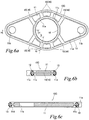
- Fig.6a, Fig.6b and Fig.6c show another modification of the gasket of the first embodiment.
- the whole shape of a gasket 10C, the inner and outer seal-forming thin portions 11c, 11d, and the inner and the outer seal portions 12, 13 of the gasket 10C in the modification are formed in the same manner as those of the above-mentioned embodiments.
- the thin portion 16 constituting the easily-deformable portion 15 of the gasket 10C is different from those in the above-mentioned embodiments.
- Four thin portions 16 are provided between the fastening bolt holes 11b, 11b on both sides so as to be connected with the inner and the outer seal-forming thin portions 11c, 11d, namely the thin portion 16 is provided at eight positions.
- Such a thin portion 16 achieves the same effect as those of the above-mentioned embodiments and reduces the weight of the core member 11 in the form of a sheet.
- Such an easily-deformable portion 15 can be selectively used for the flange portions 51, 52, referring to Fig.1 , in which heat expansion or distortion is easily caused.
- the joint portion 14 as mentioned in the embodiment of Fig. 4 can be provided on both sides of the thin portion 16 constituting the easily-deformable portion 15.
- the core member 11 in the form of a sheet can be a three-layer structure and a portion solely constituted with the base plate 110 can be used for the seal-forming thin portions 11c, 11d and the thin portion 16, namely the easily-deformable portion 15, as shown in Fig.5 .
- Other structures are the same as those of the above-mentioned embodiments, the same reference numerals are allotted to the common portions and the explanation is omitted here.
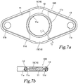
- Fig.7a and Fig.7b show another modification of the gasket of the first embodiment.
- the whole shape of a gasket 10D, the inner and outer seal-forming thin portions 11c, 11d, and the inner and the outer seal portions 12, 13 of the gasket 10D in the modification are formed in the same manner as those of the above-mentioned embodiments.
- the thin portion 16, formed as the easily-deformable portion 15 and provided at two positions, is continuously formed with the seal-forming thin portion 11c, 11d and has width larger than that of the embodiment shown in Fig.2 .
- Such a thin portion 16 with larger width achieves the same effect as those of the above-mentioned embodiments and reduces the weight of the core member 11 in the form of a sheet.
- Such an easily-deformable portion 15 can be selectively used for the flange portions 51, 52, referring to Fig.1 , and in which heat expansion or distortion is easily caused, as shown in the embodiment in Fig.6 .
- the joint portion 14 as mentioned in the embodiment of Fig. 4 can be provided on both sides of the thin portion 16 constituting the easily-deformable portion 15.
- the core member 11 in the form of a sheet can be a three-layer structure and a portion solely constituted with the base plate 110 can be used for the seal-forming thin portions 11c, 11d and the thin portion 16, namely the easily-deformable portion 15 as shown in Fig. 5 .
- Other structures are the same as those of the above-mentioned embodiments, the same reference numerals are allotted to the common portions and the explanation is omitted here.
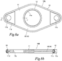
- Fig.8a and Fig.8b show another modification of the gasket of the first embodiment.
- the whole shape of a gasket 10E, the inner and outer seal-forming thin portions 11c, 11d, and the inner and the outer seal portions 12, 13 of the gasket 10E in the modification are formed in the same manner as those of the above-mentioned embodiments.
- the thin portion 16, constituting the easily-deformable portion 15, is continuously formed with the seal-forming thin portion 11c, 11d and is widely formed so as to surround the inner seal portion 12 except the vicinity of the fastening bolt holes 11b, 11b.
- Such a wide thin portion 16 remarkably achieves the effect as mentioned above and further reduces the weight of the core member 11 in the form of a sheet.
- Such an easily-deformable portion 15 can be selectively used when a gasket is used for the flange portions 51, 52, referring to Fig.1 , and the like which easily generate heat expansion or distortion, as shown in Fig.6 and Fig.7 .
- the joint portion 14 as shown in the embodiment of Fig. 4 can be provided on both sides of the thin portion 16, formed as the easily-deformable portion 15.
- the core member 11 can be a three-layer structure and a portion solely constituted with the base plate 110 can be used for the seal-forming thin portions 11c, 11d and the thin portion 16, formed as the easily-deformable portion 15, as shown in Fig.5 .
- Other structures are the same as those of the above-mentioned embodiments, the same reference numerals are allotted to the common portions and the explanation is omitted here.
- Fig.9a, Fig.9b and Fig.9c show another modification of the gasket of the first embodiment.
- the whole shape of a gasket 10F, the inner and outer seal-forming thin portions 11c, 11d, and the inner and the outer seal portions 12, 13 of the gasket 10F in the modification are formed in the same manner as those of the above-mentioned embodiments.
- the thin portion 16 constituting the easily-deformable portion 15 is not continuously formed with the seal-forming thin portion 11c or 11d and is intermittently formed at four positions around the inner seal portion 12.
- the thin portion 16 formed at four positions is a circular arc in the form of a concave groove, the arc being concentric with the opening 11a and having the same diameter as that of the opening 11a.
- the thin portion 16 includes a wide portion 16a at a position where the inner seal portion 12 and the outer seal portion 13 become closest.
- Such an easily deformable portion 15 has the effect as mentioned above.
- the thin portion 16 includes the wide portion 16a at the position where the inner seal portion 12 and the outer seal portion 13 become closest, thereby achieving the effect of the above-mentioned deformation.
- the core member 11 in the form of a sheet can be a three-layer structure and a portion solely constituted with the base plate 110 can be used for the seal-forming thin portions 11c, 11d and the thin portion 16, formed as the easily-deformable portion 15, as shown in Fig.5 .
- Other structures are the same as those of the above-mentioned embodiments, the same reference numerals are allotted to the common portions and the explanation is omitted here.
- Fig.10a, Fig.10b, Fig.10c show the second embodiment of the gasket of the present invention.
- Fig.11 and Fig.12 show the modifications.
- the easily-deformable portion 15 is constituted with a through hole 17 formed on the core member 11 in the form of a sheet.
- the whole shape of a gasket 10G, the inner and outer seal-forming thin portions 11c, 11d, and the inner and the outer seal portions 12, 13 of the gasket 10G in Fig.10a, Fig.10b, Fig.10c are formed in the same manner as those of the above-mentioned embodiments.
- the through hole 17 constituting the easily-deformable portion 15 is intermittently provided at six positions around the inner seal portion 12.
- the through hole 17 provided at six positions is in the form of a circular slot around the circular arc concentric with the opening 11a.
- the core member 11 in the vicinity of the through hole 17 easily deforms following heat expansion or distortion of the flange portions 51, 52 because the easily-deformable portion 15 is constituted with the slot-like through hole 17, thereby keeping seal ability of the gasket 10G.
- the through hole 17 reduces the weight of the core member 11.
- the core member 11 can be a three-layer structure as mentioned in the embodiment of Fig.5 .
- the opening 11a, the fastening bolt holes 11b, 11b and the through holes 17 are punched out of the core member 11 with a three-layer structure.
- Other structures are the same as the embodiment in Fig.2 and the explanation is omitted here.
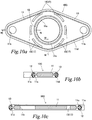
- Fig.11a, Fig.11b, Fig.11c show another modification of the second embodiment of the gasket of the present invention.
- the whole shape of a gasket 10H, the inner and outer seal-forming thin portions 11c, 11d, and the inner and the outer seal portions 12, 13 of the gasket 10H in the modification are formed in the same manner as those of the embodiment in Fig.10 .
- the through hole 17 constituting the easily-deformable portion 15 is an aperture.
- the modification is different from the embodiment in Fig. 10 in that twelve through holes 17 (apertures) are formed along the inner seal portion 12 at equal intervals around the circle concentric with the opening 11a.
- the core member 11 around the through hole 17 easily deforms following heat expansion or distortion of the flange portions 51, 52, thereby keeping seal ability of the gasket 10H.
- the through hole 17 reduces the weight of the core member 11.
- the core member 11 can be a three-layer structure as mentioned in the embodiment of Fig. 5 .
- the opening 11a, the fastening bolt holes 11b, 11b and the through holes 17 are punched out of the core member 11 with a three-layer structure.
- Other structures are the same as the embodiment in Fig. 2 and the explanation is omitted here.
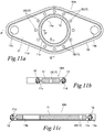
- Fig.12a, Fig.12b, Fig.12c show another modification of the second embodiment of the gasket of the present invention.
- the whole shape of a gasket 10I, the inner and outer seal-forming thin portions 11c, 11d, and the inner and the outer seal portions 12, 13 of the gasket 101 in the modification are formed in the same manner as those of the embodiment in Fig.10 .
- the gasket in the modification is different from those shown in Fig.10 and Fig.11 in that the through hole 17 constituting the easily deformable portion 15 is in the form of a circular slot concentric with the fastening bolt hole 11b in the vicinity of the fastening bolt hole 11b.
- the core member 11 around the through hole 17 easily deforms following distortion caused at the time of fastening with screws because the circular slot-like through hole 17, formed as the easily-deformable portion 15, is formed in the vicinity of the fastening bolt holes 11b, thereby keeping seal ability of the gasket 10I.
- the through hole 17 reduces the weight of the core member 11. Furthermore, deformation such as distortion caused by fastening with screws is effectively inhibited from being transmitted to other portions because the slot-like through hole 17 is formed in the vicinity of the fastening bolt holes 11b.
- the core member 11 can be a three-layer structure as mentioned in the embodiment of Fig.5 .
- the opening 11a, the fastening bolt holes 11b, 11b and through holes 17 are punched out of the core member 11 of three-layer structure.
- Other structures are the same as the embodiment in Fig. 2 and the explanation is omitted here.
- FIG.13a and Fig.13b show another modification of the embodiment of Fig. 9 .
- a gasket 10F' shown in Fig.10a is a combination of the gasket 10F in Fig.9 and the gasket 10 in Fig.2 , Fig.3 .
- Some thin portions 16 of the gasket 10 in Fig.2 and Fig.3 are replaced with the thin portions 16 of the gasket 10F in Fig. 9 at the corresponding positions.
- Such a combination remarkably achieves the effect of the easily-deformable portion 15.
- the gasket 10F'' shown in Fig.13b has the joint portion 14 shown in the embodiment of Fig.4 on both sides of the thin portion 16 which is replaced in Fig.10a .
- the easily-deformable portion 15 or the joint portion 14 shown in Fig.2 , Fig.3 , or Fig.4 can be combined with the embodiments shown in Fig.10 to Fig.12 and the combinations as shown in Fig.13a and Fig.13b can be constituted.
- the thin portion 16 and the through hole 17, constituting the easily-deformable portion 15, are not limited to those shown in the figures and other embodiment can be applied as long as they deform following heat expansion or distortion caused in the flange portions 51, 52.
- the whole shape of the gasket, the number of fastening bolt holes 11b, and the sectional shapes of the inner and outer seal-forming thin portions 11c, 11d are not limited to those shown in the figure.
- the examples of the application of the gasket 10 (10A to 101) of the present invention are exemplified to be used for the connection portion 5 in the chain case 3 shown in Fig.1 ; however, the gasket of the present invention can be used for other structures which may cause heat expansion or distortion on the attachment face.
Description
- The present invention relates to a gasket provided at a connection portion of a flow path so as not to mix cooling water in the flow path and oil charged in a chain chamber, when the flow path of cooling water of a water jacket is provided so as to penetrate the chain chamber of an automobile engine.
- A flow path of cooling water of a water jacket sometimes has to be provided so as to penetrate a chain chamber because of a layout structure of an engine and a radiator of an automobile engine (for example, referring to
Patent Literatures 1 to 3). When the flow path of the water jacket penetrates the chain chamber, a chain case is provided with a flow pipe line connected to a flow pipe of the radiator. When the chain case is attached to a cylinder block or a cylinder head by fastening with bolts, the flow pipe line of the chain case communicates with a flow port of the water jacket. Thus, the flow path communicating the flow port with the flow path line is provided. A joined portion of the flow port and the flow pipe line is positioned in the chain chamber and is provided with a seal member such as an O-ring or a gasket so as to prevent cooling water from leaking to the chain chamber from the flow path and to prevent oil from flowing into the flow path from the chain chamber. -
Patent Literature 1 discloses that a liquid gasket is provided for the joined portion.Patent Literature 2 discloses that two O-rings are concentrically provided for the joined portion, an inner O-ring is used for preventing leakage of cooling water and an outer O-ring is used for preventing leakage of oil.Patent Literature 3 discloses that a sheet-like seal member having an inner water-proof seal portion and an outer oil seal portion is provided for the joined portion. These embodiments prevent leakage of cooling water into the chain chamber and flowing of oil into the flow path at the joined portion in the chain chamber. -
Patent Literature 4 discloses a gasket provided for a joined face of a connection portion of gas piping, not for an automobile engine, the gasket comprising a sheet-like gasket at an inner circumference and a sheet-like gasket at an outer circumference. -
Patent Literature 5 describes agasket 1 in which a reinforcedcore member 2 is entirely covered with arubber material 3. Thegasket 1 has aseal projection 13 formed around the periphery of a through-hole 4 in addition to aninner seal projection 11 and anouter seal projection 12. -
Patent Literature 6 describes a seal and coupling, wherein the seal comprises a retainer 22 with radially inner and outerperipheral portions 28, 30 including a inner seal element 24 that provides both a face and radial seal, and an outer seal element 26 that provides a face seal. -
- PTL 1 : Japanese Patent Publication (not examined) No.
H10-317968 - PTL 2 : Japanese Patent Publication (not examined) No.
2010-180858 - PTL 3 : Japanese Patent Publication (not examined) No.
2012-2170 - PTL 4 : Japanese Patent Publication (not examined) No.
2010-249267 - PTL 5 : Japanese Patent Publication (not examined) No.
2005-195091 - PTL 6 :
US 2007/222159 A1 - In
Patent Literature 1, when a chain case is removed for maintenance (exchange of a chain) in the chain chamber, it is bothersome to remove a coated liquid gasket and coat a liquid gasket again. InPatent Literature 2, two kinds of O-rings are required to be prepared and to be mounted to ring grooves, respectively, in case of fastening a chain case or of the above-mentioned maintenance. InPatent Literature 3, nuts are screwed from outside of the chain case to a pair of stud bolts provided for a side wall portion at the front end around a cooling water outlet of the cylinder head, respectively, thereby a joined portion is formed between the side wall portion at the front end and a water communication pipe of the chain case. The seal member (gasket) is provided for the joined portion in a compressed condition, and the cooling water outlet and the water communication pipe are communicated, thereby constituting an outlet path of cooling water. In this case, a base body of the seal member is considered to be constituted with a sheet-like member. Therefore, when an attachment portion (a joined portion) causes heat expansion due to the heat generated at the time of operating an engine or distortion at the time of fastening with a bolt and a nut, the base body does not follow the heat expansion or the distortion, so that the seal ability of the joined portion may be deteriorated. The gasket disclosed inPatent Literature 4 comprises the sheet-like gasket at the inner circumference and the sheet-like gasket at the outer circumference and is provided between a pair of flanges fastened with a bolt and a nut under compression. However,Patent Literature 4 does not specifically refer to a problem such as heat expansion or distortion of the flange portion.Patent literature 6 discloses a seal constituting a gasket according to the preamble ofclaim 1. - The present invention is proposed in view of the above-mentioned problems and has an object to provide a gasket capable of keeping seal ability of the inner seal portion and the outer seal portion and capable of inhibiting influence over the seal ability caused by heat expansion or distortion of an attachment face.
- The present invention is defined in the claims. A gasket of the embodiment of the present invention has a core member having an opening, an inner seal portion made of elastic material and formed along an inner circumference of the opening, and an outer seal portion made of elastic material and formed along an outer circumference of the core member. The core member has a seal-forming thin portion and an easily-deformable portion, the seal-forming thin portion being configured to form the inner seal portion at the inner circumference and to form the outer seal portion at the outer circumference, and the easily-deformable portion being provided between the inner seal portion and the outer seal portion and being configured to easily deform the core member.
- In the embodiment, the inner circumference of the opening is sealed by the inner seal portion, thereby preventing an objective medium to be sealed flowing through the opening from leaking to an outer circumferential side. The outer circumference is sealed by the outer seal portion, thereby preventing another objective medium to be sealed flowing outside of the outer circumference from flowing into the opening. The structure is simple and the handling is easy, though a dual seal structure is constituted by only one gasket. Further, with the easily-deformable portion in the sheet-like core member, the sheet-like core member deforms in accordance with heat expansion or distortion of the attachment face (a flange face, for example) to which the gasket is attached and absorbs the heat expansion or the distortion, thereby the gasket is flexibly applied and keeps the seal ability. The inner seal portion and the outer seal portion to which high surface pressure is applied while being provided between the two objective members to be sealed are remarkably affected by the attachment face. However, such influence is absorbed by deformation of the easily-deformable portion provided between the inner seal portion and the outer seal portion and is inhibited to be transferred to the other seal portion, thereby keeping the seal ability.
- The easily-deformable portion of the gasket of one embodiment of the present invention can have a thin portion or a through hole. In the embodiment, the sheet-like core member following the heat expansion or distortion as mentioned above is effectively deformed because of the thin portion or the through hole and influence over the seal ability in the inner seal portion and the outer seal portion is inhibited. When the sheet-like core member, made of metal, can be easily produced together with the thin portion or the through hole by a sheet-metal processing, thereby reducing the weight of the sheet-like core member.
- In one embodiment of the gasket of the present invention, either the thin portion or the through hole can be continuously formed with the seal-forming thin portion of the inner seal portion and the seal-forming thin portion of the outer seal portion.
- In the embodiment, the thin portion or the through hole is continuously formed with the seal-forming thin portion, so that the core member is easily processed. The thin portion or the through hole is connected with the seal-forming thin portion, thereby the sheet-like core member is easily deformed following the heat expansion and the distortion of the attachment face of the sheet-like core member.
- In one embodiment of the gasket of the present invention, either the thin portion or the through hole can have a joint portion made of elastic material, the joint portion being configured to be joined with the inner seal portion and the outer seal portion.
- In the embodiment, in case that the inner seal portion and the outer seal portion are constituted with a rubber molded body, when rubber material is injected into an injection port with the sheet-like core member processed in a predetermined shape and positioned in a cavity of a mold, the inner seal portion and the outer seal portion can be simultaneously molded via the joint portion even if there is only one injection port.
- In the gasket of the present invention, a plurality of fastening bolt holes are provided between the inner seal portion and the outer seal portion. A seal portion is not required to be provided around the fastening bolt hole because the inner and the outer seal portions are provided.
- In one embodiment of the gasket of the present invention, the easily-deformable portion can be independently formed from the fastening bolt holes.
- In the embodiment, the deformation of the easily-deformable portion does not affect the fixing function of the objective member to be sealed and the gasket in case of fastening with a bolt, thereby exerting the above-mentioned seal ability of the gasket of the embodiment of the present invention.
- In one embodiment of the gasket of the present invention, the easily-deformable portion can be formed between the fastening bolt holes.
- As the easily-deformable portion is provided for a position apart from the fastening bolt holes, fastening of the bolts causes stress at the position, thereby the gasket can be flexibly adapted to heat expansion or distortion on the attachment face in the embodiment. At the bolt fastening portion largely affected by deformation of the attachment face, the influence is inhibited from being transferred to the other portion, thereby keeping the seal ability.
- In one embodiment of the gasket of the present invention, the easily-deformable portion can be formed between the inner seal portion and the fastening bolt hole or between the outer seal potion and the fastening bolt hole.
- As mentioned above, as the easily-deformable portion is provided for a position apart from the fastening bolt holes, fastening of the bolts causes stress at the position, thereby the gasket can be flexibly adapted to the heat expansion or the distortion on the attachment face in the embodiment. The influence caused by fastening with a bolt is inhibited from being transferred to the other portion, thereby keeping the seal ability.
- In one embodiment of the gasket of the present invention, the easily-deformable portion can be formed at a plurality of regions of the core member.
- The above-mentioned embodiment can be appropriately adapted even when there are a plurality of portions in which heat expansion or distortion is easily generated.
- The gasket of the embodiment of the present invention can appropriately keep seal ability of the inner seal portion and the outer seal portion with a simple structure. In addition, the sheet-like core member of the gasket has the easily-deformable portion, thereby effectively inhibiting influence over the seal ability, caused by heat expansion or distortion of the attachment face.
-
-
Fig.1 is a longitudinal sectional view showing that a gasket of the present invention is provided in a connection portion of a drain path penetrating a chain case from a water jacket of an engine. -
Fig.2 is a plan view showing the first embodiment of a gasket of the present invention. -
Fig.3a is a sectional view taken in the directions of the arrow along the line A-A ofFig.2 andFig.3b is a sectional view taken in the directions of the arrow along the line B-B ofFig.2 . -
Fig.4a is a plan view showing a modification of the gasket of the above-mentioned embodiment,Fig.4b is a sectional view taken in the directions of the arrow along the line C-C ofFig.4a and Fig.4c is a sectional view taken in the directions of the arrow along the line D-D ofFig.4a . -
Fig.5a is a plan view showing another modification of the gasket of the above-mentioned embodiment,Fig.5b is a sectional view taken in the directions of the arrow along the line E-E ofFig. 5a and Fig. 5c is a sectional view taken in the directions of the arrow along the line F-F ofFig.5a . -
Fig.6a is a plan view showing another modification of the gasket of the above-mentioned embodiment,Fig. 6b is a sectional view taken in the directions of the arrow along the line G-G ofFig. 6a and Fig. 6c is a sectional view taken in the directions of the arrow along the line H-H ofFig.6a . -
Fig.7a is a plan view showing another modification of the gasket of the above-mentioned embodiment andFig.7b is a sectional view taken in the directions of the arrow along the line I-I ofFig.7a . -
Fig.8a is a plan view showing another modification of the gasket of the above-mentioned embodiment andFig.8b is a sectional view taken in the directions of the arrow along the line J-J ofFig.8a . -
Fig.9a is a plan view showing another modification of the gasket of the above-mentioned embodiment,Fig.9b is a sectional view taken in the directions of the arrow along the line K-K ofFig.9a , and -
Fig. 9c is a sectional view taken in the directions of the arrow along the line L-L ofFig.9a . -
Fig.10a is a plan view showing a gasket of the second embodiment of the present invention,Fig.10b is a sectional view taken in the directions of the arrow along the line M-M ofFig.10a and Fig.10c is a sectional view taken in the directions of the arrow along the line N-N ofFig.10a . -
Fig.11a is a plan view showing a modification of the above-mentioned embodiment,Fig.11b is a sectional view taken in the directions of the arrow along the line O-O ofFig.11a and Fig.11c is a sectional view taken in the directions of the arrow along the line P-P ofFig.11a . -
Fig.12a is a plan view showing another modification of the above-mentioned embodiment,Fig.12b is a sectional view taken in the directions of the arrow along the line Q-Q ofFig.12a and Fig.12c is a sectional view taken in the directions of the arrow along the line R-R ofFig.12a . -
Fig.13a and Fig.13b are plan views showing modifications of the embodiment ofFig.9 . - The embodiment of the present invention is explained referring to the attached drawings. An example of the application of the gasket of the present invention is explained referring to
Fig.1. Fig.1 shows that agasket 10 of the embodiment of the present invention is provided for aconnection portion 5 of a drain path 4 (flow path) penetrating achain case 3, i.e. a front cover, to a radiator (not shown) from awater jacket 2 provided for acylinder block 1 of an automobile engine. Adrain port 2a of thewater jacket 2 is provided for thecylinder block 1 and apipe 41 on thecylinder block 1 side is provided for thedrain port 2a. Aflange portion 51 is provided at the leading end of thepipe 41. The peripheral portion of thechain case 3 is fixed to the front side of thecylinder block 1 with a bolt, not shown, and achain chamber 30 is formed between thechain case 3 and thefront wall 1a (water jacket wall) of thecylinder block 1. A chain or a timing belt, not shown, for transmitting power from a crank shaft to another auxiliary machine is provided in thechain chamber 30. Lubricant oil, not shown, is filled in thechain chamber 30 for smoothly transmitting power with a chain and the like. - A
pipe 42 on thechain case 3 side is provided so as to penetrate thechain case 3 at a position corresponding to thepipe line 41 on thecylinder block 1 side. Aflange portion 52, facing theflange portion 51 on thecylinder block 1 side, is formed on the base side of thepipe 42, on thecylinder block 1 side, thereby constituting theconnection portion 5 with bothflange portions flange portions flange portion 51 on thecylinder block 1 side has twobolt holes bolt holes flange portion 52 on thechain case 3 side so as to penetrate thechain case 3 while communicating withbolt holes chain case 3 at positions corresponding to thebolt holes bolts chain case 3 through thebolt holes chain case 3, thebolt hole 52a of theflange portion 52 and thebolt hole 51a of theflange portion 51, to twofemale screw portions bolt hole 51a of thefront wall 1a of thecylinder block 1. At the time of fastening with twobolts gasket 10 of the embodiment of the present invention is provided under pressure between the mating faces of theflange portions pipes flange portions drain path 4 is formed from thedrain port 2a of thewater jacket 2 to the radiator, not shown. - A stud bolt, not shown, can be fixed to the
front wall 1a of thecylinder block 1 and a nut, not shown, can be screwed to the stud bolt from the outside of thechain case 3, without using thebolts water jacket 2 is exemplified; however, the above-mentioned structure can be provided for a water supply side. In the figure, thepipe 42 including theflange portion 52 extending into thecylinder block 1 side is provided for thechain case 3 in a projecting manner. However, thedrain path 4 can be formed without having such a projectingpipe 42. In the figure, thedrain path 4 is integrally provided on the outer side of thechain case 3. However, another pipe can be provided on the outer side of thechain case 3 so as to be watertightly connected with thedrain path 4. - The first embodiment of the gasket provided for the
connection portion 5 is explained also referring toFig.2 ,Fig.3a and Fig.3b .Fig.4 to Fig. 9 show modifications of the first embodiment. In the modifications, an easily-deformable portion 15 is constituted with athin portion 16 of thecore member 11 in the form of a sheet. Thegasket 10 of the first embodiment shown inFig.2 ,Fig.3a and Fig.3b has thecore member 11 having anopening 11a, aninner seal portion 12 made of elastic material and formed along the inner circumference of theopening 11a, and anouter seal portion 13 made of elastic material and formed along the outer circumference of thecore member 11. The elastic material of theinner seal portion 12 and theouter seal portion 13 is rubber. Thecore member 11 is a metal plate and the outer shape is substantially lozenged in conformity with the outer shape of theflange portions opening 11a is circular of which center is concentric with the intersection of diagonal lines of the lozenge outer shape and the circular shape is substantially in conformity with the sectional shape of thedrain path 4. Thecore member 11 hasfastening bolt holes bolt holes flange portions core member 11, theopening 11a and thefastening bolt holes - The
core member 11 in the form of a sheet has seal-formingthin portions inner seal portion 12 and theouter seal portion 13. Thecore member 11 further has an easily-deformable portion 15 for facilitating deformation of thecore member 11 between the inner and theouter seal portions deformable portions 15 in this embodiment is constituted with thethin portion 16 continuously formed with the inner seal-formingthin portion 11c and the outer seal-formingthin portions 11d so as to have the same thickness thereof. Thethin portion 16 is formed at two middle portions between thefastening bolt holes fastening bolt holes thin portion 16 is provided at a position which does not affect thefastening bolt holes thin portion 16 is continuously formed from the seal-formingthin portions thin portions core member 11 from both sides. The core member processed in a predetermined form is provided in a cavity of a mold, unvulcanized rubber material is injected, and molded by vulcanization. Then, theinner seal portion 12 and theouter seal portion 13 are integrally formed with the seal-formingthin portions - Elastic material of the
seal portions inner seal portion 12 and theouter seal portion 13 can be integrally formed on the front face and the back face of the seal-formingthin portions - The above-mentioned
gasket 10 is provided under pressure between theflange portions connection portion 5 by fastening a bolt, not shown, at the periphery of thechain case 3 and the twobolts 6 for forming a drain path to thecylinder block 1, as shown inFig.1 . Thechain chamber 30 is formed between thechain case 3 and thefront wall 1a of thecylinder block 1 by attaching thechain case 3 with the bolt and lubricant oil, not shown, is filled in thechain chamber 30. Thedrain path 4 is formed by connecting theflange portions gasket 10. Cooling water flows though thedrain path 4 from thewater jacket 2 to the radiator, not shown. As thegasket 10 is provided under pressure between theflange portions inner seal portion 12 and theouter seal portion 13 are compressed in the thickness direction of thecore member 11 in the form of a sheet and contact under pressure the opposing faces of theflange portions drain path 4 is prevented from leaking out of thechain chamber 30 through theconnection portion 5. Oil charged in thechain chamber 30 is prevented from flowing to thedrain path 4 from theconnection portion 5 because of theouter seal portion 13 contacting under pressure the opposing faces of theflange portions - Although the
connection portion 5 of thepipes chain chamber 30, oil in thechain chamber 30 and cooling water flowing in thedrain path 4 are surely prevented from being mixed, thereby increasing variation of the layout structure of an engine. Thecore member 11 in the form of a sheet has the easily-deformable portion 15 constituted with thethin portion 16 and correspondingly deforms even if theflange portions inner seal portion 12 and theouter seal portion 13 is not affected. The easily-deformable portion 15 is provided around the middle between thefastening bolt holes outer seal portions flange portions gasket 10 by being fastened with thebolts deformable portion 15 because the easily-deformable portion 15 is formed in a position other than thefastening bolt holes fastening bolt holes bolts fastening bolt holes outer seal portions deformable portion 15 effectively achieves the above-mentioned effects. -
Fig.4a, Fig.4b and Fig.4c show a modification of the gasket of the first embodiment. The whole shape of agasket 10A, the inner and outer seal-formingthin portions outer seal portions thin portion 16 constituting the easily-deformable portion 15 of thegasket 10A in the modification are formed in the same manner as those of thegasket 10 shown inFig.2 andFig.3 . Thegasket 10A is different from thegasket 10 in that ajoint portion 14 made of elastic material and connected with theinner seal portion 12 and theouter seal portion 13 is provided on both sides of thethin portion 16, namely the easily-deformable portion 15. Thejoint portion 14 is made of rubber material like theinner seal portion 12 and theouter seal portion 13. In case of vulcanization molding as mentioned above, unvulcanized rubber is injected from one port and theinner seal portion 12 and theouter seal portion 13 are simultaneously molded by vulcanization via thejoint portion 14. In this case, thejoint portion 14 is molded so as to have thickness smaller than that of the tops of theinner seal portion 12 and theouter seal portion 13. Theinner seal portion 12 and theouter seal portion 13, being connected via thejoint portion 14, are integrally fixed with thecore member 11 in the form of a sheet and are restrained by thecore member 11, thereby achieving the seal ability independently without being affected by the deformation caused by the above-mentioned compression. The above-mentioned easily-deformable portion 15 (thin portion 16) achieves the above-mentioned effect together with thejoint portion 14. - Other structures are the same as the embodiment shown in
Fig. 2 ,Fig. 3a, Fig.3b , the same reference numerals are allotted to the common portions and the explanation is omitted here. -
Fig.5a, Fig.5b and Fig.5c show another modification of the gasket of the first embodiment. The whole shape of agasket 10B, the inner and outer seal-formingthin portions outer seal portions thin portion 16 constituting the easily-deformable portion 15 of thegasket 10B in the modification are formed in the same manner as those of the above-mentionedgaskets gasket 10B in this modification is different from the above-mentioned embodiments in that thecore member 11 in the form of a sheet is a three-layer structure of abase plate 110, andside plates base plate 110 without theside plates thin portion 16, namely the easily-deformable portion 15. Thebase plate 110 and theside plates base plate 110 and theside plates side wall 111, the production cost is reduced. When thecore member 11 has a three-layer structure of thebase plate 110 and theside plates deformable portion 15,thin portion 16, is achieved in the same manner as those of the above-mentioned embodiments. Also in this modification, thejoint portion 14 as mentioned in the embodiment ofFig. 4 can be provided on both sides of thethin portion 16 constituting the easily-deformable portion 15. Other structures are the same as those of the above-mentioned embodiments, the same reference numerals are allotted to the common portions and the explanation is omitted here. -
Fig.6a, Fig.6b and Fig.6c show another modification of the gasket of the first embodiment. The whole shape of agasket 10C, the inner and outer seal-formingthin portions outer seal portions gasket 10C in the modification are formed in the same manner as those of the above-mentioned embodiments. Thethin portion 16 constituting the easily-deformable portion 15 of thegasket 10C is different from those in the above-mentioned embodiments. Fourthin portions 16 are provided between thefastening bolt holes thin portions thin portion 16 is provided at eight positions. Such athin portion 16 achieves the same effect as those of the above-mentioned embodiments and reduces the weight of thecore member 11 in the form of a sheet. Such an easily-deformable portion 15 can be selectively used for theflange portions Fig.1 , in which heat expansion or distortion is easily caused. - Also in this modification, the
joint portion 14 as mentioned in the embodiment ofFig. 4 can be provided on both sides of thethin portion 16 constituting the easily-deformable portion 15. In addition, thecore member 11 in the form of a sheet can be a three-layer structure and a portion solely constituted with thebase plate 110 can be used for the seal-formingthin portions thin portion 16, namely the easily-deformable portion 15, as shown inFig.5 . Other structures are the same as those of the above-mentioned embodiments, the same reference numerals are allotted to the common portions and the explanation is omitted here. -
Fig.7a and Fig.7b show another modification of the gasket of the first embodiment. The whole shape of agasket 10D, the inner and outer seal-formingthin portions outer seal portions gasket 10D in the modification are formed in the same manner as those of the above-mentioned embodiments. Thethin portion 16, formed as the easily-deformable portion 15 and provided at two positions, is continuously formed with the seal-formingthin portion Fig.2 . Such athin portion 16 with larger width achieves the same effect as those of the above-mentioned embodiments and reduces the weight of thecore member 11 in the form of a sheet. Such an easily-deformable portion 15 can be selectively used for theflange portions Fig.1 , and in which heat expansion or distortion is easily caused, as shown in the embodiment inFig.6 . - Also in this modification, the
joint portion 14 as mentioned in the embodiment ofFig. 4 can be provided on both sides of thethin portion 16 constituting the easily-deformable portion 15. In addition, thecore member 11 in the form of a sheet can be a three-layer structure and a portion solely constituted with thebase plate 110 can be used for the seal-formingthin portions thin portion 16, namely the easily-deformable portion 15 as shown inFig. 5 . Other structures are the same as those of the above-mentioned embodiments, the same reference numerals are allotted to the common portions and the explanation is omitted here. -
Fig.8a and Fig.8b show another modification of the gasket of the first embodiment. The whole shape of agasket 10E, the inner and outer seal-formingthin portions outer seal portions gasket 10E in the modification are formed in the same manner as those of the above-mentioned embodiments. Thethin portion 16, constituting the easily-deformable portion 15, is continuously formed with the seal-formingthin portion inner seal portion 12 except the vicinity of thefastening bolt holes thin portion 16 remarkably achieves the effect as mentioned above and further reduces the weight of thecore member 11 in the form of a sheet. Such an easily-deformable portion 15 can be selectively used when a gasket is used for theflange portions Fig.1 , and the like which easily generate heat expansion or distortion, as shown inFig.6 andFig.7 . - Also in this modification, the
joint portion 14 as shown in the embodiment ofFig. 4 can be provided on both sides of thethin portion 16, formed as the easily-deformable portion 15. In addition, thecore member 11 can be a three-layer structure and a portion solely constituted with thebase plate 110 can be used for the seal-formingthin portions thin portion 16, formed as the easily-deformable portion 15, as shown inFig.5 . Other structures are the same as those of the above-mentioned embodiments, the same reference numerals are allotted to the common portions and the explanation is omitted here. -
Fig.9a, Fig.9b and Fig.9c show another modification of the gasket of the first embodiment. The whole shape of agasket 10F, the inner and outer seal-formingthin portions outer seal portions gasket 10F in the modification are formed in the same manner as those of the above-mentioned embodiments. - The
thin portion 16 constituting the easily-deformable portion 15 is not continuously formed with the seal-formingthin portion inner seal portion 12. Thethin portion 16 formed at four positions is a circular arc in the form of a concave groove, the arc being concentric with theopening 11a and having the same diameter as that of theopening 11a. Thethin portion 16 includes awide portion 16a at a position where theinner seal portion 12 and theouter seal portion 13 become closest. Such an easilydeformable portion 15 has the effect as mentioned above. Thethin portion 16 includes thewide portion 16a at the position where theinner seal portion 12 and theouter seal portion 13 become closest, thereby achieving the effect of the above-mentioned deformation. - Also in the modification, the
core member 11 in the form of a sheet can be a three-layer structure and a portion solely constituted with thebase plate 110 can be used for the seal-formingthin portions thin portion 16, formed as the easily-deformable portion 15, as shown inFig.5 . Other structures are the same as those of the above-mentioned embodiments, the same reference numerals are allotted to the common portions and the explanation is omitted here. -
Fig.10a, Fig.10b, Fig.10c show the second embodiment of the gasket of the present invention.Fig.11 andFig.12 show the modifications. In these embodiments, the easily-deformable portion 15 is constituted with a throughhole 17 formed on thecore member 11 in the form of a sheet. - The whole shape of a
gasket 10G, the inner and outer seal-formingthin portions outer seal portions gasket 10G inFig.10a, Fig.10b, Fig.10c are formed in the same manner as those of the above-mentioned embodiments. The throughhole 17 constituting the easily-deformable portion 15 is intermittently provided at six positions around theinner seal portion 12. The throughhole 17 provided at six positions is in the form of a circular slot around the circular arc concentric with theopening 11a. Thecore member 11 in the vicinity of the throughhole 17 easily deforms following heat expansion or distortion of theflange portions deformable portion 15 is constituted with the slot-like throughhole 17, thereby keeping seal ability of thegasket 10G. In addition, the throughhole 17 reduces the weight of thecore member 11. - In this embodiment, the
core member 11 can be a three-layer structure as mentioned in the embodiment ofFig.5 . Theopening 11a, thefastening bolt holes holes 17 are punched out of thecore member 11 with a three-layer structure. Other structures are the same as the embodiment inFig.2 and the explanation is omitted here. -
Fig.11a, Fig.11b, Fig.11c show another modification of the second embodiment of the gasket of the present invention. The whole shape of agasket 10H, the inner and outer seal-formingthin portions outer seal portions gasket 10H in the modification are formed in the same manner as those of the embodiment inFig.10 . The throughhole 17 constituting the easily-deformable portion 15 is an aperture. The modification is different from the embodiment inFig. 10 in that twelve through holes 17 (apertures) are formed along theinner seal portion 12 at equal intervals around the circle concentric with theopening 11a. Thecore member 11 around the throughhole 17 easily deforms following heat expansion or distortion of theflange portions gasket 10H. In addition, the throughhole 17 reduces the weight of thecore member 11. - In this embodiment, the
core member 11 can be a three-layer structure as mentioned in the embodiment ofFig. 5 . Theopening 11a, thefastening bolt holes holes 17 are punched out of thecore member 11 with a three-layer structure. Other structures are the same as the embodiment inFig. 2 and the explanation is omitted here. -
Fig.12a, Fig.12b, Fig.12c show another modification of the second embodiment of the gasket of the present invention. The whole shape of a gasket 10I, the inner and outer seal-formingthin portions outer seal portions gasket 101 in the modification are formed in the same manner as those of the embodiment inFig.10 . The gasket in the modification is different from those shown inFig.10 andFig.11 in that the throughhole 17 constituting the easilydeformable portion 15 is in the form of a circular slot concentric with thefastening bolt hole 11b in the vicinity of thefastening bolt hole 11b. Thecore member 11 around the throughhole 17 easily deforms following distortion caused at the time of fastening with screws because the circular slot-like throughhole 17, formed as the easily-deformable portion 15, is formed in the vicinity of thefastening bolt holes 11b, thereby keeping seal ability of the gasket 10I. In addition, the throughhole 17 reduces the weight of thecore member 11. Furthermore, deformation such as distortion caused by fastening with screws is effectively inhibited from being transmitted to other portions because the slot-like throughhole 17 is formed in the vicinity of thefastening bolt holes 11b. - In this embodiment, the
core member 11 can be a three-layer structure as mentioned in the embodiment ofFig.5 . Theopening 11a, thefastening bolt holes holes 17 are punched out of thecore member 11 of three-layer structure. Other structures are the same as the embodiment inFig. 2 and the explanation is omitted here. -
Fig.13a and Fig.13b show another modification of the embodiment ofFig. 9 . Agasket 10F' shown inFig.10a is a combination of thegasket 10F inFig.9 and thegasket 10 inFig.2 ,Fig.3 . Somethin portions 16 of thegasket 10 inFig.2 andFig.3 are replaced with thethin portions 16 of thegasket 10F inFig. 9 at the corresponding positions. Such a combination remarkably achieves the effect of the easily-deformable portion 15. Thegasket 10F'' shown inFig.13b has thejoint portion 14 shown in the embodiment ofFig.4 on both sides of thethin portion 16 which is replaced inFig.10a . Therefore, the above-mentioned effect of thejoint portion 14 is added to the embodiment inFig.13a . The easily-deformable portion 15 or thejoint portion 14 shown inFig.2 ,Fig.3 , orFig.4 can be combined with the embodiments shown inFig.10 to Fig.12 and the combinations as shown inFig.13a and Fig.13b can be constituted. - The
thin portion 16 and the throughhole 17, constituting the easily-deformable portion 15, are not limited to those shown in the figures and other embodiment can be applied as long as they deform following heat expansion or distortion caused in theflange portions fastening bolt holes 11b, and the sectional shapes of the inner and outer seal-formingthin portions connection portion 5 in thechain case 3 shown inFig.1 ; however, the gasket of the present invention can be used for other structures which may cause heat expansion or distortion on the attachment face. -
- 10, 10A to 10I
- gasket
- 11
- core member in the form of sheet
- 11a
- opening
- 11b
- fastening bolt hole
- 11c
- inner seal-forming thin portion
- 11d
- outer seal-forming thin portion
- 12
- inner seal portion
- 13
- outer seal portion
- 14
- joint portion
- 15
- easily-deformable portion
- 16
- thin portion
- 17
- through hole
Claims (8)
- A gasket suitable for sealing a space between two members by being interposed between attachment faces of the two members and by being compressed therebetween, the gasket comprising: a core member (11), the core member (11) being sheet-like and having an opening (11a); an inner seal portion (12), the inner seal portion (12) being made of elastic material and formed along an inner circumference of the opening (lla); and an outer seal portion (13), the outer seal portion (13) being made of elastic material and formed along an outer circumference of the core member (11); the core member (11) comprising: a seal-forming thin portion (11c, 11d) and an easily-deformable portion (15), the seal-forming thin portion (11c, 11d) having a thickness that is thinner than other portions of the core member (11) and being configured to form the inner seal portion (12) at the inner circumference and to form the outer seal portion (13) at the outer circumference, and the easily-deformable portion (15) being provided between the inner seal portion (12) and the outer seal portion (13) and being configured to easily deform the core member (11), characterized in that a plurality of fastening bolt holes (11b) are provided between the inner seal portion (12) and the outer seal portion (13).
- The gasket as set forth in claim 1, wherein the easily-deformable portion comprises a thin portion or a through hole.
- The gasket as set forth in claim 2, wherein either the thin portion or the through hole is continuously formed with the seal-forming thin portion of the inner seal portion and the seal-forming thin portion of the outer seal portion.
- The gasket as set forth in claim 3, wherein either the thin portion or the through hole has a joint portion made of elastic material, the joint portion being configured to be joined with the inner seal portion and the outer seal portion.
- The gasket as set forth in claim 1, 2, 3 or 4, wherein the easily-deformable portion is independently formed from the fastening bolt holes.
- The gasket as set forth in claim 1, 2, 3 or 4, wherein the easily-deformable portion is formed between the fastening bolt holes.
- The gasket as set forth in claim 1, 2, 3 or 4, wherein the easily-deformable portion is formed between the inner seal portion and the fastening bolt hole or between the outer seal potion and the fastening bolt hole.
- The gasket as set forth in any one of claims 1 to 7, wherein the easily-deformable portion is formed at a plurality of regions of the core member.
Applications Claiming Priority (2)
| Application Number | Priority Date | Filing Date | Title |
|---|---|---|---|
| JP2012221994A JP5723846B2 (en) | 2012-10-04 | 2012-10-04 | gasket |
| PCT/JP2013/076493 WO2014054561A1 (en) | 2012-10-04 | 2013-09-30 | Gasket |
Publications (3)
| Publication Number | Publication Date |
|---|---|
| EP2905515A1 EP2905515A1 (en) | 2015-08-12 |
| EP2905515A4 EP2905515A4 (en) | 2016-06-01 |
| EP2905515B1 true EP2905515B1 (en) | 2020-08-26 |
Family
ID=50434888
Family Applications (1)
| Application Number | Title | Priority Date | Filing Date |
|---|---|---|---|
| EP13843332.1A Active EP2905515B1 (en) | 2012-10-04 | 2013-09-30 | Gasket |
Country Status (5)
| Country | Link |
|---|---|
| US (1) | US10174872B2 (en) |
| EP (1) | EP2905515B1 (en) |
| JP (1) | JP5723846B2 (en) |
| CN (1) | CN104704270B (en) |
| WO (1) | WO2014054561A1 (en) |
Families Citing this family (14)
| Publication number | Priority date | Publication date | Assignee | Title |
|---|---|---|---|---|
| EP3006802B1 (en) * | 2013-05-31 | 2018-05-16 | Kyowa Industry Co., Ltd. | Flange joining structure and seal body used therein |
| JP6276572B2 (en) * | 2013-12-06 | 2018-02-07 | Nok株式会社 | Gasket mold and manufacturing method |
| CN106192295B (en) * | 2015-05-05 | 2019-04-19 | 青岛海尔洗衣机有限公司 | A kind of washing machine inner tub sealing mounting structure |
| JP6779669B2 (en) * | 2016-06-08 | 2020-11-04 | ナブテスコ株式会社 | Seal member and gear device |
| CN106499802A (en) * | 2016-12-19 | 2017-03-15 | 中车长春轨道客车股份有限公司 | Sensor rubber gasket and the gear-box with the sensor rubber gasket |
| CN111819378B (en) * | 2018-03-14 | 2022-10-18 | 三菱电机株式会社 | Gasket and refrigeration cycle device |
| GB2572553A (en) | 2018-03-29 | 2019-10-09 | Airbus Operations Ltd | Aircraft fuel tank isolator |
| CN110118133A (en) * | 2019-06-20 | 2019-08-13 | 无锡模达科技有限公司 | A kind of crankcase dust excluding plate sealing noise reduction |
| US10975823B2 (en) * | 2019-08-16 | 2021-04-13 | Caterpillar Inc. | Fastener-component sub-assembly |
| US11181004B2 (en) * | 2020-02-07 | 2021-11-23 | Raytheon Technologies Corporation | Confinement of a rope seal about a passage using a backing plate |
| DE202020101730U1 (en) * | 2020-03-31 | 2021-07-02 | Reinz-Dichtungs-Gmbh | Cylinder head gasket |
| US11621453B2 (en) * | 2020-07-08 | 2023-04-04 | Reinz-Dichtungs-Gmbh | Foldable gasket with continuous sealing contour |
| JP2023551573A (en) * | 2020-12-10 | 2023-12-08 | ボブスト メックス ソシエテ アノニム | Positioning devices and assemblies for holding flat flexible elements and sheet material processing machines |
| JP7311183B1 (en) * | 2022-02-24 | 2023-07-19 | 石川ガスケット株式会社 | Seal couplings and gaskets |
Family Cites Families (38)
| Publication number | Priority date | Publication date | Assignee | Title |
|---|---|---|---|---|
| US2191044A (en) * | 1937-11-10 | 1940-02-20 | Aluminium Plant & Vessel Co | Liquid treating apparatus of the built-up type |
| US3231289A (en) * | 1962-01-26 | 1966-01-25 | Parker Hannifin Corp | Sealing gasket |
| US3302953A (en) * | 1963-02-25 | 1967-02-07 | Clarence O Glasgow | Gasket ring and conduit coupling |
| US3578346A (en) * | 1969-01-29 | 1971-05-11 | Parker Hannifin Corp | Sealed joint and gasket therefor |
| US3738670A (en) * | 1971-09-27 | 1973-06-12 | Parker Hannifin Corp | Sectional gasket |
| US3930656A (en) * | 1974-02-22 | 1976-01-06 | Parker-Hannifin Corporation | Sealed joint and gasket therefor |
| US4294477A (en) * | 1977-06-08 | 1981-10-13 | Vetco Inc. | Flexible ring gasket retainer for flanged connectors |
| US4607851A (en) * | 1977-11-30 | 1986-08-26 | Metex Corporation | Method of making composite wire mesh seal |
| US4272085A (en) * | 1978-10-07 | 1981-06-09 | Kawasaki Jukogyo Kabushiki Kaisha | Cylinder head gasket for a liquid cooled internal combustion engine |
| FR2483522B1 (en) * | 1980-06-02 | 1985-07-19 | Curty Soc | CYLINDER HEAD GASKET FOR INTERNAL COMBUSTION ENGINE |
| JPS57122856U (en) * | 1981-01-26 | 1982-07-30 | ||
| JPS6018246U (en) * | 1983-07-18 | 1985-02-07 | 日産ディーゼル工業株式会社 | Internal combustion engine cylinder head gasket |
| US4535996A (en) * | 1985-01-18 | 1985-08-20 | Felt Products Mfg. Co. | Gasket assembly for oil pans and the like and method of making same |
| US5267740A (en) * | 1992-02-20 | 1993-12-07 | Fel-Pro Incorporated | Metal head gasket with integrated sealing aids |
| CN1072342C (en) * | 1996-04-16 | 2001-10-03 | 诺克株式会社 | Gasket |
| US5890719A (en) * | 1996-08-27 | 1999-04-06 | Parker-Hannifin Corporation | Combination metal and elastomer cylinder head gasket |
| JP3601571B2 (en) | 1997-05-15 | 2004-12-15 | スズキ株式会社 | Engine cooling system |
| FR2768211B1 (en) * | 1997-09-09 | 1999-10-22 | Curty Payen Sa | STATIC SEAL |
| JP3792934B2 (en) * | 1999-05-12 | 2006-07-05 | 内山工業株式会社 | Gasket and manufacturing method thereof |
| DE60121240T2 (en) * | 2000-03-23 | 2007-05-31 | Nichias Corp. | metal seal |
| US6318768B1 (en) * | 2000-05-01 | 2001-11-20 | International Truck & Engine Corp | Tubing coupler with primary and secondary sealing |
| JP2002081543A (en) * | 2000-09-04 | 2002-03-22 | Nippon Gasket Co Ltd | Metal gasket |
| DE10324667A1 (en) * | 2003-05-30 | 2004-12-16 | STE Gesellschaft für Dichtungstechnik mbH | Cylinder head gasket |
| US7744095B2 (en) * | 2003-09-17 | 2010-06-29 | Uchiyama Manufacturing Corp. | Cylinder head gasket |
| JP4538238B2 (en) * | 2004-01-07 | 2010-09-08 | 三菱電線工業株式会社 | gasket |
| US20050269788A1 (en) * | 2004-06-02 | 2005-12-08 | Grunfeld Aron A | Gasket assembly and method |
| US8186691B2 (en) * | 2006-02-17 | 2012-05-29 | Parker-Hannifin Corporation | Composite seal and coupling |
| US7766391B2 (en) * | 2006-04-05 | 2010-08-03 | Doowon Climate Control Co., Ltd. | Pipe connecting structure |
| JP2008031872A (en) * | 2006-07-26 | 2008-02-14 | Yamaha Marine Co Ltd | Seal structure by metal gasket |
| DE112006003987B4 (en) * | 2006-08-22 | 2014-04-10 | Japan Metal Gasket Co. Ltd. | Connection structure of metal plates |
| CA2682705A1 (en) * | 2007-04-24 | 2008-10-30 | Reinz-Dichtungs-Gmbh | Metallic flat gasket |
| JP5287313B2 (en) | 2009-02-09 | 2013-09-11 | 日産自動車株式会社 | Internal combustion engine seal structure |
| JP2010249267A (en) | 2009-04-17 | 2010-11-04 | Tokyo Gas Co Ltd | Gasket |
| CN201858136U (en) * | 2010-05-10 | 2011-06-08 | 浙江省上虞市油封制造有限公司 | Sealing ring for automobile turning pump |
| JP2012002170A (en) | 2010-06-18 | 2012-01-05 | Toyota Motor Corp | Cooling water outlet structure for internal combustion engine |
| CN201827359U (en) * | 2010-08-31 | 2011-05-11 | 铁岭市友邦橡胶制品有限公司 | Combined sealing gasket for rear cover of oil pump |
| CN202170997U (en) * | 2011-08-18 | 2012-03-21 | 昌图长汽密封制品厂 | Double-lipped rubber plane sealing gasket |
| US8960682B2 (en) * | 2013-03-14 | 2015-02-24 | Federal-Mogul Corporation | Hybrid ring welded cylinder head gasket |
-
2012
- 2012-10-04 JP JP2012221994A patent/JP5723846B2/en active Active
-
2013
- 2013-09-30 WO PCT/JP2013/076493 patent/WO2014054561A1/en active Application Filing
- 2013-09-30 CN CN201380052183.5A patent/CN104704270B/en active Active
- 2013-09-30 US US14/433,582 patent/US10174872B2/en active Active
- 2013-09-30 EP EP13843332.1A patent/EP2905515B1/en active Active
Non-Patent Citations (1)
| Title |
|---|
| None * |
Also Published As
| Publication number | Publication date |
|---|---|
| JP5723846B2 (en) | 2015-05-27 |
| EP2905515A1 (en) | 2015-08-12 |
| CN104704270B (en) | 2017-10-03 |
| CN104704270A (en) | 2015-06-10 |
| WO2014054561A1 (en) | 2014-04-10 |
| US10174872B2 (en) | 2019-01-08 |
| JP2014074453A (en) | 2014-04-24 |
| EP2905515A4 (en) | 2016-06-01 |
| US20150260317A1 (en) | 2015-09-17 |
Similar Documents
| Publication | Publication Date | Title |
|---|---|---|
| EP2905515B1 (en) | Gasket | |
| US6547255B1 (en) | Fluid seals | |
| US3944260A (en) | Pipe repair fittings | |
| EP2792916B1 (en) | Seal structure and flow-path connection part | |
| US20030201611A1 (en) | Method of making a segmented gasket having a continuous seal member | |
| US20090273143A1 (en) | Gasket | |
| US8118551B2 (en) | Casing and fluid machine | |
| US6050614A (en) | Bolted seal joint assembly | |
| CN101501373B (en) | Shaft seal device | |
| US20170074401A1 (en) | Press-in-place gasket | |
| TW201437600A (en) | Shell and tube heat exchanger, end cover and method of manufacturing same | |
| JP6262544B2 (en) | Flange joint reinforcing structure and annular protective member used therefor | |
| US20200032904A1 (en) | Gasket | |
| JP4149036B2 (en) | Pipe flange leakage repair mechanism | |
| JPH051727Y2 (en) | ||
| CN213323329U (en) | Vehicle and steering system and steering engine thereof | |
| KR200389223Y1 (en) | Pipe joint structure | |
| JP2019138385A (en) | Flange-type pipe joint for small-diameter pipe | |
| EP3153747A1 (en) | Variable compression height integrated seal | |
| EP3137793B1 (en) | Pressure controlled dynamic seal with captured fluid transfer tubes | |
| JP2005076478A (en) | Delivery pipe | |
| EP4283102A1 (en) | Exhaust gas pipe, and engine | |
| JP3811875B2 (en) | mechanical seal | |
| JP7246905B2 (en) | sealing device | |
| JP2000046198A (en) | Mechanical seal |
Legal Events
| Date | Code | Title | Description |
|---|---|---|---|
| PUAI | Public reference made under article 153(3) epc to a published international application that has entered the european phase |
Free format text: ORIGINAL CODE: 0009012 |
|
| 17P | Request for examination filed |
Effective date: 20150428 |
|
| AK | Designated contracting states |
Kind code of ref document: A1 Designated state(s): AL AT BE BG CH CY CZ DE DK EE ES FI FR GB GR HR HU IE IS IT LI LT LU LV MC MK MT NL NO PL PT RO RS SE SI SK SM TR |
|
| AX | Request for extension of the european patent |
Extension state: BA ME |
|
| DAX | Request for extension of the european patent (deleted) | ||
| RA4 | Supplementary search report drawn up and despatched (corrected) |
Effective date: 20160429 |
|
| RIC1 | Information provided on ipc code assigned before grant |
Ipc: F16J 15/12 20060101ALI20160422BHEP Ipc: F16J 15/10 20060101AFI20160422BHEP Ipc: F16L 19/02 20060101ALI20160422BHEP |
|
| STAA | Information on the status of an ep patent application or granted ep patent |
Free format text: STATUS: EXAMINATION IS IN PROGRESS |
|
| 17Q | First examination report despatched |
Effective date: 20180620 |
|
| GRAP | Despatch of communication of intention to grant a patent |
Free format text: ORIGINAL CODE: EPIDOSNIGR1 |
|
| STAA | Information on the status of an ep patent application or granted ep patent |
Free format text: STATUS: GRANT OF PATENT IS INTENDED |
|
| INTG | Intention to grant announced |
Effective date: 20200318 |
|
| GRAS | Grant fee paid |
Free format text: ORIGINAL CODE: EPIDOSNIGR3 |
|
| GRAA | (expected) grant |
Free format text: ORIGINAL CODE: 0009210 |
|
| STAA | Information on the status of an ep patent application or granted ep patent |
Free format text: STATUS: THE PATENT HAS BEEN GRANTED |
|
| REG | Reference to a national code |
Ref country code: DE Ref legal event code: R081 Ref document number: 602013072019 Country of ref document: DE Owner name: UCHIYAMA MANUFACTURING CORP., OKAYAMA-SHI, JP Free format text: FORMER OWNER: UCHIYAMA MANUFACTURING CORP., OKAYAMA-SHI, OKAYAMA, JP Ref country code: DE Ref legal event code: R081 Ref document number: 602013072019 Country of ref document: DE Owner name: TOYOTA JIDOSHA KABUSHIKI KAISHA, TOYOTA-SHI, JP Free format text: FORMER OWNER: UCHIYAMA MANUFACTURING CORP., OKAYAMA-SHI, OKAYAMA, JP |
|
| AK | Designated contracting states |
Kind code of ref document: B1 Designated state(s): AL AT BE BG CH CY CZ DE DK EE ES FI FR GB GR HR HU IE IS IT LI LT LU LV MC MK MT NL NO PL PT RO RS SE SI SK SM TR |
|
| REG | Reference to a national code |
Ref country code: GB Ref legal event code: FG4D |
|
| REG | Reference to a national code |
Ref country code: CH Ref legal event code: EP |
|
| REG | Reference to a national code |
Ref country code: AT Ref legal event code: REF Ref document number: 1306693 Country of ref document: AT Kind code of ref document: T Effective date: 20200915 |
|
| REG | Reference to a national code |
Ref country code: IE Ref legal event code: FG4D |
|
| REG | Reference to a national code |
Ref country code: DE Ref legal event code: R096 Ref document number: 602013072019 Country of ref document: DE |
|
| REG | Reference to a national code |
Ref country code: LT Ref legal event code: MG4D |
|
| PG25 | Lapsed in a contracting state [announced via postgrant information from national office to epo] |
Ref country code: PT Free format text: LAPSE BECAUSE OF FAILURE TO SUBMIT A TRANSLATION OF THE DESCRIPTION OR TO PAY THE FEE WITHIN THE PRESCRIBED TIME-LIMIT Effective date: 20201228 Ref country code: LT Free format text: LAPSE BECAUSE OF FAILURE TO SUBMIT A TRANSLATION OF THE DESCRIPTION OR TO PAY THE FEE WITHIN THE PRESCRIBED TIME-LIMIT Effective date: 20200826 Ref country code: BG Free format text: LAPSE BECAUSE OF FAILURE TO SUBMIT A TRANSLATION OF THE DESCRIPTION OR TO PAY THE FEE WITHIN THE PRESCRIBED TIME-LIMIT Effective date: 20201126 Ref country code: SE Free format text: LAPSE BECAUSE OF FAILURE TO SUBMIT A TRANSLATION OF THE DESCRIPTION OR TO PAY THE FEE WITHIN THE PRESCRIBED TIME-LIMIT Effective date: 20200826 Ref country code: NO Free format text: LAPSE BECAUSE OF FAILURE TO SUBMIT A TRANSLATION OF THE DESCRIPTION OR TO PAY THE FEE WITHIN THE PRESCRIBED TIME-LIMIT Effective date: 20201126 Ref country code: HR Free format text: LAPSE BECAUSE OF FAILURE TO SUBMIT A TRANSLATION OF THE DESCRIPTION OR TO PAY THE FEE WITHIN THE PRESCRIBED TIME-LIMIT Effective date: 20200826 Ref country code: GR Free format text: LAPSE BECAUSE OF FAILURE TO SUBMIT A TRANSLATION OF THE DESCRIPTION OR TO PAY THE FEE WITHIN THE PRESCRIBED TIME-LIMIT Effective date: 20201127 Ref country code: FI Free format text: LAPSE BECAUSE OF FAILURE TO SUBMIT A TRANSLATION OF THE DESCRIPTION OR TO PAY THE FEE WITHIN THE PRESCRIBED TIME-LIMIT Effective date: 20200826 |
|
| REG | Reference to a national code |
Ref country code: NL Ref legal event code: MP Effective date: 20200826 |
|
| REG | Reference to a national code |
Ref country code: AT Ref legal event code: MK05 Ref document number: 1306693 Country of ref document: AT Kind code of ref document: T Effective date: 20200826 |
|
| PG25 | Lapsed in a contracting state [announced via postgrant information from national office to epo] |
Ref country code: RS Free format text: LAPSE BECAUSE OF FAILURE TO SUBMIT A TRANSLATION OF THE DESCRIPTION OR TO PAY THE FEE WITHIN THE PRESCRIBED TIME-LIMIT Effective date: 20200826 Ref country code: LV Free format text: LAPSE BECAUSE OF FAILURE TO SUBMIT A TRANSLATION OF THE DESCRIPTION OR TO PAY THE FEE WITHIN THE PRESCRIBED TIME-LIMIT Effective date: 20200826 Ref country code: NL Free format text: LAPSE BECAUSE OF FAILURE TO SUBMIT A TRANSLATION OF THE DESCRIPTION OR TO PAY THE FEE WITHIN THE PRESCRIBED TIME-LIMIT Effective date: 20200826 Ref country code: PL Free format text: LAPSE BECAUSE OF FAILURE TO SUBMIT A TRANSLATION OF THE DESCRIPTION OR TO PAY THE FEE WITHIN THE PRESCRIBED TIME-LIMIT Effective date: 20200826 Ref country code: IS Free format text: LAPSE BECAUSE OF FAILURE TO SUBMIT A TRANSLATION OF THE DESCRIPTION OR TO PAY THE FEE WITHIN THE PRESCRIBED TIME-LIMIT Effective date: 20201226 |
|
| PG25 | Lapsed in a contracting state [announced via postgrant information from national office to epo] |
Ref country code: EE Free format text: LAPSE BECAUSE OF FAILURE TO SUBMIT A TRANSLATION OF THE DESCRIPTION OR TO PAY THE FEE WITHIN THE PRESCRIBED TIME-LIMIT Effective date: 20200826 Ref country code: DK Free format text: LAPSE BECAUSE OF FAILURE TO SUBMIT A TRANSLATION OF THE DESCRIPTION OR TO PAY THE FEE WITHIN THE PRESCRIBED TIME-LIMIT Effective date: 20200826 Ref country code: CZ Free format text: LAPSE BECAUSE OF FAILURE TO SUBMIT A TRANSLATION OF THE DESCRIPTION OR TO PAY THE FEE WITHIN THE PRESCRIBED TIME-LIMIT Effective date: 20200826 Ref country code: RO Free format text: LAPSE BECAUSE OF FAILURE TO SUBMIT A TRANSLATION OF THE DESCRIPTION OR TO PAY THE FEE WITHIN THE PRESCRIBED TIME-LIMIT Effective date: 20200826 Ref country code: SM Free format text: LAPSE BECAUSE OF FAILURE TO SUBMIT A TRANSLATION OF THE DESCRIPTION OR TO PAY THE FEE WITHIN THE PRESCRIBED TIME-LIMIT Effective date: 20200826 |
|
| REG | Reference to a national code |
Ref country code: CH Ref legal event code: PL |
|
| REG | Reference to a national code |
Ref country code: DE Ref legal event code: R097 Ref document number: 602013072019 Country of ref document: DE |
|
| PG25 | Lapsed in a contracting state [announced via postgrant information from national office to epo] |
Ref country code: AT Free format text: LAPSE BECAUSE OF FAILURE TO SUBMIT A TRANSLATION OF THE DESCRIPTION OR TO PAY THE FEE WITHIN THE PRESCRIBED TIME-LIMIT Effective date: 20200826 Ref country code: AL Free format text: LAPSE BECAUSE OF FAILURE TO SUBMIT A TRANSLATION OF THE DESCRIPTION OR TO PAY THE FEE WITHIN THE PRESCRIBED TIME-LIMIT Effective date: 20200826 Ref country code: ES Free format text: LAPSE BECAUSE OF FAILURE TO SUBMIT A TRANSLATION OF THE DESCRIPTION OR TO PAY THE FEE WITHIN THE PRESCRIBED TIME-LIMIT Effective date: 20200826 Ref country code: MC Free format text: LAPSE BECAUSE OF FAILURE TO SUBMIT A TRANSLATION OF THE DESCRIPTION OR TO PAY THE FEE WITHIN THE PRESCRIBED TIME-LIMIT Effective date: 20200826 |
|
| REG | Reference to a national code |
Ref country code: BE Ref legal event code: MM Effective date: 20200930 |
|
| PG25 | Lapsed in a contracting state [announced via postgrant information from national office to epo] |
Ref country code: SK Free format text: LAPSE BECAUSE OF FAILURE TO SUBMIT A TRANSLATION OF THE DESCRIPTION OR TO PAY THE FEE WITHIN THE PRESCRIBED TIME-LIMIT Effective date: 20200826 Ref country code: LU Free format text: LAPSE BECAUSE OF NON-PAYMENT OF DUE FEES Effective date: 20200930 |
|
| PLBE | No opposition filed within time limit |
Free format text: ORIGINAL CODE: 0009261 |
|
| STAA | Information on the status of an ep patent application or granted ep patent |
Free format text: STATUS: NO OPPOSITION FILED WITHIN TIME LIMIT |
|
| PG25 | Lapsed in a contracting state [announced via postgrant information from national office to epo] |
Ref country code: IT Free format text: LAPSE BECAUSE OF FAILURE TO SUBMIT A TRANSLATION OF THE DESCRIPTION OR TO PAY THE FEE WITHIN THE PRESCRIBED TIME-LIMIT Effective date: 20200826 |
|
| 26N | No opposition filed |
Effective date: 20210527 |
|
| PG25 | Lapsed in a contracting state [announced via postgrant information from national office to epo] |
Ref country code: SI Free format text: LAPSE BECAUSE OF FAILURE TO SUBMIT A TRANSLATION OF THE DESCRIPTION OR TO PAY THE FEE WITHIN THE PRESCRIBED TIME-LIMIT Effective date: 20200826 Ref country code: LI Free format text: LAPSE BECAUSE OF NON-PAYMENT OF DUE FEES Effective date: 20200930 Ref country code: IE Free format text: LAPSE BECAUSE OF NON-PAYMENT OF DUE FEES Effective date: 20200930 Ref country code: CH Free format text: LAPSE BECAUSE OF NON-PAYMENT OF DUE FEES Effective date: 20200930 Ref country code: BE Free format text: LAPSE BECAUSE OF NON-PAYMENT OF DUE FEES Effective date: 20200930 |
|
| PG25 | Lapsed in a contracting state [announced via postgrant information from national office to epo] |
Ref country code: TR Free format text: LAPSE BECAUSE OF FAILURE TO SUBMIT A TRANSLATION OF THE DESCRIPTION OR TO PAY THE FEE WITHIN THE PRESCRIBED TIME-LIMIT Effective date: 20200826 Ref country code: MT Free format text: LAPSE BECAUSE OF FAILURE TO SUBMIT A TRANSLATION OF THE DESCRIPTION OR TO PAY THE FEE WITHIN THE PRESCRIBED TIME-LIMIT Effective date: 20200826 Ref country code: CY Free format text: LAPSE BECAUSE OF FAILURE TO SUBMIT A TRANSLATION OF THE DESCRIPTION OR TO PAY THE FEE WITHIN THE PRESCRIBED TIME-LIMIT Effective date: 20200826 |
|
| PG25 | Lapsed in a contracting state [announced via postgrant information from national office to epo] |
Ref country code: MK Free format text: LAPSE BECAUSE OF FAILURE TO SUBMIT A TRANSLATION OF THE DESCRIPTION OR TO PAY THE FEE WITHIN THE PRESCRIBED TIME-LIMIT Effective date: 20200826 |
|
| REG | Reference to a national code |
Ref country code: DE Ref legal event code: R084 Ref document number: 602013072019 Country of ref document: DE |
|
| PGFP | Annual fee paid to national office [announced via postgrant information from national office to epo] |
Ref country code: GB Payment date: 20230927 Year of fee payment: 11 |
|
| REG | Reference to a national code |
Ref country code: GB Ref legal event code: 746 Effective date: 20231025 |
|
| PGFP | Annual fee paid to national office [announced via postgrant information from national office to epo] |
Ref country code: FR Payment date: 20230915 Year of fee payment: 11 Ref country code: DE Payment date: 20230929 Year of fee payment: 11 |